EP3834698B1 - Gehäuse für eine wäschebehandlungsmaschine oder spülmaschine - Google Patents
Gehäuse für eine wäschebehandlungsmaschine oder spülmaschine Download PDFInfo
- Publication number
- EP3834698B1 EP3834698B1 EP20209231.8A EP20209231A EP3834698B1 EP 3834698 B1 EP3834698 B1 EP 3834698B1 EP 20209231 A EP20209231 A EP 20209231A EP 3834698 B1 EP3834698 B1 EP 3834698B1
- Authority
- EP
- European Patent Office
- Prior art keywords
- cover
- housing
- spring
- housing part
- front housing
- Prior art date
- Legal status (The legal status is an assumption and is not a legal conclusion. Google has not performed a legal analysis and makes no representation as to the accuracy of the status listed.)
- Active
Links
Images


Classifications
-
- A—HUMAN NECESSITIES
- A47—FURNITURE; DOMESTIC ARTICLES OR APPLIANCES; COFFEE MILLS; SPICE MILLS; SUCTION CLEANERS IN GENERAL
- A47L—DOMESTIC WASHING OR CLEANING; SUCTION CLEANERS IN GENERAL
- A47L15/00—Washing or rinsing machines for crockery or tableware
- A47L15/42—Details
- A47L15/4251—Details of the casing
-
- D—TEXTILES; PAPER
- D06—TREATMENT OF TEXTILES OR THE LIKE; LAUNDERING; FLEXIBLE MATERIALS NOT OTHERWISE PROVIDED FOR
- D06F—LAUNDERING, DRYING, IRONING, PRESSING OR FOLDING TEXTILE ARTICLES
- D06F39/00—Details of washing machines not specific to a single type of machines covered by groups D06F9/00 - D06F27/00
- D06F39/12—Casings; Tubs
-
- A—HUMAN NECESSITIES
- A47—FURNITURE; DOMESTIC ARTICLES OR APPLIANCES; COFFEE MILLS; SPICE MILLS; SUCTION CLEANERS IN GENERAL
- A47L—DOMESTIC WASHING OR CLEANING; SUCTION CLEANERS IN GENERAL
- A47L15/00—Washing or rinsing machines for crockery or tableware
- A47L15/42—Details
- A47L15/4293—Arrangements for programme selection, e.g. control panels; Indication of the selected programme, programme progress or other parameters of the programme, e.g. by using display panels
Definitions
- the invention relates to a housing for a laundry treatment machine or dishwasher, comprising, based on the operational installation position of the machine, a front housing part, two opposite side walls, and a housing cover, the housing cover being attached to the side walls themselves or by means of a support structure and the front housing part is attached to the side walls and / or the lid by means of fasteners.
- Laundry treatment machines generally include a housing made from sheet metal parts, in which components and assemblies are accommodated. Furthermore, a control panel is attached to the front of the housing, with which the user can influence the settings and the operation of the device.
- the housing generally comprises a front housing part, two opposite side walls, and a housing cover, with the housing cover being fastened to the side walls themselves or by means of a supporting structure and the front housing part being fastened to the side walls and/or the cover by means of fastening means.
- a housing for a laundry treatment machine in which the assembly is improved by specially designed fastening means.
- the attachment of the housing cover to use hook-shaped clamping claws, which are guided in the housing cover and the hook-shaped projection engages under the upper fold of the side part.
- the known housing structures also have the disadvantage that access to the interior of the housing for maintenance or repair work is very complex.
- the object of the invention is therefore to improve a housing for a laundry treatment machine or dishwasher and to eliminate the disadvantages mentioned.
- the object is achieved by a housing having the features of patent claim 1 and by a machine according to claim 12.
- Advantageous refinements and developments of the invention result from the respective dependent claims.
- the advantages that can be achieved with the invention are that the assembly for fastening the housing parts, in particular the front housing part with the side parts and the cover, is very simple. Furthermore, a good and secure hold of the parts is ensured, with the housing parts being able to be loosened and removed again very easily and conveniently. Especially for devices in commercial use, frequent maintenance work is required due to the rough conditions of use and the more intensive operation, whereby access to the interior of the device can be made easily, quickly and without cumbersome work on the housing.
- the fastening means is designed to fasten the front housing part and/or a hood-shaped control panel to the side parts and to fasten the cover to the side parts to fix a side wall with the housing cover and with the front housing part in the predetermined end position.
- the fastening means is designed as a latching means in order to fix the housing cover with the front housing part in the predetermined end position. This eliminates the need for cumbersome screw connections that require free space for assembly in the event of maintenance.
- the fastening means comprises at least one spring, which comprises a contact leg and a spring leg, the contact leg being fixed to the cover, the front housing part having a latching edge in order to receive the corresponding spring leg and thereby fix the cover on the front housing part .
- the spring is attached to the cover in such a way that the spring leg extends protruding from the cover and can lock behind a corresponding locking edge on the front housing part or the panel part.
- the spring is attached to a front fold of the cover and the front housing part has a fold with an opening on its rear side in order to accommodate the spring, in particular the spring leg, in the assembled state, with an edge side of the opening forming the latching edge.
- the spring is designed as a leaf spring for all versions, with the two legs being at an angle, preferably an acute angle, to one another.
- the cover, the side parts and the front housing part are made of sheet metal or the parts mentioned at least comprise sheet metal.
- the parts are made of sheet metal and are provided with the folds mentioned above.
- Sheet metal is particularly robust and stable, so that self-supporting machine structures are possible.
- Housing parts made of sheet metal are particularly suitable and advantageous for machines used commercially.
- the spring leg is designed as a starting bevel with an indentation in order to deform against the spring force when pushed in along the corresponding latching edge, the spring leg springing back in the end position so that the indentation comes to rest on the latching edge.
- the front edge of the cover includes an outwardly protruding tab, on the surface of which the spring is attached or fastened, with the contact leg resting flat on the surface of the tab and with the tab is screwed or riveted.
- the tab is formed as a partial segment cut out of the front fold, which is very easy to implement and is sufficiently stable.
- the lid has an inwardly directed bevel or web with an elongated hole on its two opposite outer sides on the underside, and the side walls each have a pin with a mushroom head on their upper sides, which engages in the elongated hole when the lid placed on the side walls.
- the elongated hole is shaped as a keyhole with a widened opening cross-section and an adjoining narrower channel, so that the cover can be placed at a distance from the front housing part and then pushed in the direction of the front housing part, with the mushroom head protruding through the widened opening cross-section passes and moves behind the channel when moving, the keyhole and the
- the corresponding pins with their mushroom heads are arranged or positioned in such a way that when the cover is placed on the spring or spring leg is at a distance from the rear fold of the front housing part and that the spring leg slides into the opening of the fold of the front housing part when it is moved in the direction of the front housing part protrudes into the front part of the housing.
- the region of the elongated hole rises obliquely upwards or is designed to thicken upwards in order to bring about a frictional or pressure-acting contact with the mushroom head. This applies a force to the lid, urging it toward the top edges of the side walls. This ensures a tight fit and a small gap between the cover and side walls.
- the spring and/or the elongated hole is dimensioned in such a way that in the end position a gap remains between the front edge of the cover and the rear edge of the front housing part, through which the spring leg can be pushed from the outside, preferably from the top of the housing. is accessible.
- a flat tool such as a spatula or a blade, the spring leg can be pressed out of the locking position through the gap, so that it is easier to slide the cover into the open position.
- the invention also relates to a laundry treatment machine or dishwasher with a housing according to one of the above-mentioned embodiments.
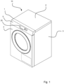
- a laundry treatment machine 10 which comprises a housing 1 with a front wall 2, a cover 4 and two opposite side parts or side walls 3.
- the machine also includes a control panel 5, in which control elements and display elements 25 are arranged so that they are accessible to the user.
- the control panel 5 also includes a control part (not shown), which is configured for running the set programs or other actions in the laundry treatment machine.
- the hood-shaped control panel 5 as a front housing part executed.
- the housing 1 can contain other components, such as the rear wall or base part (both not shown).
- a spring 30 is provided as a fastening means, which is attached to a fold 41 of the cover 4 .
- a lug 42 is arranged on the fold 41 , against which the contact leg 31 of the spring 30 rests and is fastened to the lug 42 by means of a rivet 32 .
- the tab 42 protrudes at an angle from the front fold 41 so that the spring 30 protrudes from the front of the fold 41 or extends outwards from the fold 41 .
- the spring 30 protrudes through a passage 52 in the rear bevel or rear wall 51 of the hood-shaped panel 5 .
- the spring leg 33 is provided with a stepped kink 34 which brings about the latching connection with the latching edge 53 on the fold 51 of the hood-shaped panel 5 .
- the step-shaped kink 34 thus forms the barb, which is snapped in behind the locking edge 53 .
- the cover 4 has on its underside, ie directed towards the upper edges of the side walls, a bevel 21 or web with a slot 44 which is designed as a keyhole with an entry opening 45 and a slot area 46 .
- a peg 60 with a mushroom head 61 is attached to the upper edge of the side wall 2 in such a way that the peg 60 protrudes through the elongated hole 44 or through the slot area 46, with the mushroom head 61 partially covering the slot area 46 and thereby attaching the cover 4 the side wall 2 fixed.
- the fastening described is provided for both sides of the housing 1.
- the keyhole 44 and the associated pin 60 with the mushroom head 61 are dimensioned such that when the cover 4 is placed on the lower part or the side walls 2, the mushroom head 61 passes through the entry opening.
- the slot 44 is moved in such a way that the slot 46 slides under the mushroom head 61, so that the mushroom head 61 prevents the pin 60 from emerging from the slot 46, and the cover 4 is thus attached to the side wall 2 or the lower case chassis.
- the web 21 has a thickened area 47 in the area of the slot 46 in order to achieve a play-free contact of the mushroom head 61 on the web 21 and thus a tight fit of the cover 4 .
- the hood-shaped cover part 5 on the front is screwed or riveted to the side walls 2 .
- a gap 55 which has a width in the range from 0.5 mm to 2 mm.
- a spatula can be inserted into this gap 55 in order to press the spring leg 33 out of the locking position.
- the cover 4 can then be pushed backwards with the latching mechanism released and removed upwards. Access to the interior of the device 10 is thus released, for example for maintenance purposes.
- FIG. 3 shows the lid 4 taken by itself in a perspective view from above.
- the cover 4 is provided with the bevel 41 on the front side.
- springs 30 are attached as fasteners for detachable connection to the front housing part 2, 5 ( 1 ) serve.
- a slot 44 which is shaped as a keyhole and is intended for connection to a corresponding pin 60 ( 2 ) on the lower part of the housing.
- the keyhole 44 and the associated pin 60 with the mushroom head 61 are dimensioned in such a way that the mushroom head 61 passes through the entry opening 45 when the cover 4 is placed on the lower part or the side walls 2 .
- the slot 44 is moved in such a way that the slot 46 slides under the mushroom head 61, so that the mushroom head 61 prevents the pin from escaping from the slot 46, and the cover 4 is thus attached to the side wall 2 or the lower case chassis.
- the cover 4 shows the cover 4 with the fastening means 40 in a detailed sectional view.
- the cover 4, the hood-shaped front part 5 and the side walls are preferably made of sheet metal.
- the cover 4 includes an outwardly angled lug 42 on its front fold 41.
- the lug 42 is cut out of the sheet metal material of the front fold 41 and angled outward, so that no further fastening means for fastening the lug 42 are necessary.
- the torsion spring 30 shaped as an angle is attached to the upper flat side of the tab 42 , the leg spring 31 resting flat on the tab and the rivet 32 is fastened to it. It can be seen that the spring leg 33 has a stepped kink 34 which provides the locking catch for the fixed locking edge 53 on the housing part 5 to be fastened.
Landscapes
- Engineering & Computer Science (AREA)
- Textile Engineering (AREA)
- Main Body Construction Of Washing Machines And Laundry Dryers (AREA)
- Casings For Electric Apparatus (AREA)
Applications Claiming Priority (1)
| Application Number | Priority Date | Filing Date | Title |
|---|---|---|---|
| DE102019133984.7A DE102019133984A1 (de) | 2019-12-11 | 2019-12-11 | Gehäuse für eine Wäschebehandlungsmaschine oder Spülmaschine |
Publications (2)
| Publication Number | Publication Date |
|---|---|
| EP3834698A1 EP3834698A1 (de) | 2021-06-16 |
| EP3834698B1 true EP3834698B1 (de) | 2023-06-28 |
Family
ID=73554233
Family Applications (1)
| Application Number | Title | Priority Date | Filing Date |
|---|---|---|---|
| EP20209231.8A Active EP3834698B1 (de) | 2019-12-11 | 2020-11-23 | Gehäuse für eine wäschebehandlungsmaschine oder spülmaschine |
Country Status (4)
| Country | Link |
|---|---|
| EP (1) | EP3834698B1 (pl) |
| DE (1) | DE102019133984A1 (pl) |
| ES (1) | ES2949179T3 (pl) |
| PL (1) | PL3834698T3 (pl) |
Family Cites Families (8)
| Publication number | Priority date | Publication date | Assignee | Title |
|---|---|---|---|---|
| ES470524A1 (es) | 1978-05-26 | 1979-02-01 | Domar Sa | Perfeccionamientos en los bastidores y carcasas de maquinas lavadoras de ropa |
| US5584549A (en) * | 1995-04-26 | 1996-12-17 | General Electric Company | Front serviceable appliance cabinet |
| DE19613320C1 (de) * | 1996-04-03 | 1997-04-30 | Bauknecht Hausgeraete | Vorrichtung zum Befestigen einer Arbeitsplatte auf einer Haushaltsmaschine |
| DE19843228C1 (de) | 1998-09-22 | 2000-01-27 | Miele & Cie | Befestigungsanordnung für den Gehäusedeckel eines Haushaltgerätes |
| KR20050081454A (ko) * | 2004-02-13 | 2005-08-19 | 엘지전자 주식회사 | 드럼 세탁기의 탑 플레이트 설치 구조 |
| DE102004036175B4 (de) * | 2004-07-26 | 2008-01-31 | Miele & Cie. Kg | Haushaltgerät, insbesondere Wäschebehandlungsmaschine wie Waschmaschine, Waschtrockner oder Wäschetrockner, mit einer Bedienblende und Verfahren zur Montage einer Bedienblende |
| DE102005025808B3 (de) * | 2005-06-02 | 2006-08-03 | Miele & Cie. Kg | Frontbeladbares Wäschebehandlungsgerät mit einer Bedienblende |
| AU2015268670B2 (en) * | 2015-12-11 | 2022-02-03 | Electrolux Thailand Co., Ltd | Lid for Washing Machine |
-
2019
- 2019-12-11 DE DE102019133984.7A patent/DE102019133984A1/de not_active Withdrawn
-
2020
- 2020-11-23 ES ES20209231T patent/ES2949179T3/es active Active
- 2020-11-23 PL PL20209231.8T patent/PL3834698T3/pl unknown
- 2020-11-23 EP EP20209231.8A patent/EP3834698B1/de active Active
Also Published As
| Publication number | Publication date |
|---|---|
| PL3834698T3 (pl) | 2023-10-02 |
| EP3834698A1 (de) | 2021-06-16 |
| DE102019133984A1 (de) | 2021-06-17 |
| ES2949179T3 (es) | 2023-09-26 |
Similar Documents
| Publication | Publication Date | Title |
|---|---|---|
| DE29916465U1 (de) | Tisch-Einheit | |
| EP3756507A1 (de) | Schublade | |
| EP1063379B1 (de) | Scharnier | |
| DE102008011672B4 (de) | Kabelführungsvorrichtung | |
| DE19932443C2 (de) | Scharnier | |
| DE3625063C2 (pl) | ||
| EP3834698B1 (de) | Gehäuse für eine wäschebehandlungsmaschine oder spülmaschine | |
| DE19602813A1 (de) | Einrichtung zur Befestigung einer Haltemechanik | |
| DE68902081T2 (de) | Anhaltevorrichtung fuer schwenkelemente. | |
| WO2015074933A1 (de) | Haltevorrichtung für ein gehäuse und verfahren zur montage des gehäuses unter verwendung der haltevorrichtung | |
| DE102017121385A1 (de) | Blendenträger und Schubkasten | |
| AT406983B (de) | Roll-laden | |
| EP3009043B1 (de) | Schubkasten mit einer verstellvorrichtung für die ausrichtung der frontblende | |
| CH688115A5 (de) | Vorrichtung zur Aufnahme eines Tafelelements. | |
| EP3860400B1 (de) | Befestigungsvorrichtung für eine blende eines schubkastens an einer zarge | |
| AT520803A1 (de) | Schubladenseitenwand | |
| EP4116534A1 (de) | Gehäuse für einen türantrieb sowie türantrieb | |
| DE9311098U1 (de) | Halter für die Textilbespannung von Reinigungsgeräten | |
| DE3307532C2 (pl) | ||
| DE3409732C2 (de) | Einbau-Aschenbecher für Kraftfahrzeuge | |
| EP3325744B1 (de) | Verfahren zur demontage einer führungsanordnung für eine schiebetür | |
| DE19828233A1 (de) | Wandkonsole | |
| DE10136680A1 (de) | Schaltschrank | |
| EP0291840A1 (de) | Kopf- oder Fusssteller mit mehreren Stufenrastungen | |
| DE102017127527B4 (de) | Führungsschiene für ein Linearlager |
Legal Events
| Date | Code | Title | Description |
|---|---|---|---|
| PUAI | Public reference made under article 153(3) epc to a published international application that has entered the european phase |
Free format text: ORIGINAL CODE: 0009012 |
|
| STAA | Information on the status of an ep patent application or granted ep patent |
Free format text: STATUS: THE APPLICATION HAS BEEN PUBLISHED |
|
| AK | Designated contracting states |
Kind code of ref document: A1 Designated state(s): AL AT BE BG CH CY CZ DE DK EE ES FI FR GB GR HR HU IE IS IT LI LT LU LV MC MK MT NL NO PL PT RO RS SE SI SK SM TR |
|
| STAA | Information on the status of an ep patent application or granted ep patent |
Free format text: STATUS: REQUEST FOR EXAMINATION WAS MADE |
|
| 17P | Request for examination filed |
Effective date: 20211216 |
|
| RBV | Designated contracting states (corrected) |
Designated state(s): AL AT BE BG CH CY CZ DE DK EE ES FI FR GB GR HR HU IE IS IT LI LT LU LV MC MK MT NL NO PL PT RO RS SE SI SK SM TR |
|
| GRAP | Despatch of communication of intention to grant a patent |
Free format text: ORIGINAL CODE: EPIDOSNIGR1 |
|
| STAA | Information on the status of an ep patent application or granted ep patent |
Free format text: STATUS: GRANT OF PATENT IS INTENDED |
|
| INTG | Intention to grant announced |
Effective date: 20230316 |
|
| GRAS | Grant fee paid |
Free format text: ORIGINAL CODE: EPIDOSNIGR3 |
|
| GRAA | (expected) grant |
Free format text: ORIGINAL CODE: 0009210 |
|
| STAA | Information on the status of an ep patent application or granted ep patent |
Free format text: STATUS: THE PATENT HAS BEEN GRANTED |
|
| AK | Designated contracting states |
Kind code of ref document: B1 Designated state(s): AL AT BE BG CH CY CZ DE DK EE ES FI FR GB GR HR HU IE IS IT LI LT LU LV MC MK MT NL NO PL PT RO RS SE SI SK SM TR |
|
| REG | Reference to a national code |
Ref country code: CH Ref legal event code: EP |
|
| REG | Reference to a national code |
Ref country code: DE Ref legal event code: R084 Ref document number: 502020003940 Country of ref document: DE |
|
| REG | Reference to a national code |
Ref country code: AT Ref legal event code: REF Ref document number: 1581956 Country of ref document: AT Kind code of ref document: T Effective date: 20230715 |
|
| REG | Reference to a national code |
Ref country code: IE Ref legal event code: FG4D Free format text: LANGUAGE OF EP DOCUMENT: GERMAN |
|
| REG | Reference to a national code |
Ref country code: DE Ref legal event code: R096 Ref document number: 502020003940 Country of ref document: DE |
|
| REG | Reference to a national code |
Ref country code: GB Ref legal event code: 746 Effective date: 20230717 |
|
| REG | Reference to a national code |
Ref country code: ES Ref legal event code: FG2A Ref document number: 2949179 Country of ref document: ES Kind code of ref document: T3 Effective date: 20230926 |
|
| REG | Reference to a national code |
Ref country code: LT Ref legal event code: MG9D |
|
| PG25 | Lapsed in a contracting state [announced via postgrant information from national office to epo] |
Ref country code: SE Free format text: LAPSE BECAUSE OF FAILURE TO SUBMIT A TRANSLATION OF THE DESCRIPTION OR TO PAY THE FEE WITHIN THE PRESCRIBED TIME-LIMIT Effective date: 20230628 Ref country code: NO Free format text: LAPSE BECAUSE OF FAILURE TO SUBMIT A TRANSLATION OF THE DESCRIPTION OR TO PAY THE FEE WITHIN THE PRESCRIBED TIME-LIMIT Effective date: 20230928 |
|
| REG | Reference to a national code |
Ref country code: NL Ref legal event code: MP Effective date: 20230628 |
|
| PG25 | Lapsed in a contracting state [announced via postgrant information from national office to epo] |
Ref country code: RS Free format text: LAPSE BECAUSE OF FAILURE TO SUBMIT A TRANSLATION OF THE DESCRIPTION OR TO PAY THE FEE WITHIN THE PRESCRIBED TIME-LIMIT Effective date: 20230628 Ref country code: NL Free format text: LAPSE BECAUSE OF FAILURE TO SUBMIT A TRANSLATION OF THE DESCRIPTION OR TO PAY THE FEE WITHIN THE PRESCRIBED TIME-LIMIT Effective date: 20230628 Ref country code: LV Free format text: LAPSE BECAUSE OF FAILURE TO SUBMIT A TRANSLATION OF THE DESCRIPTION OR TO PAY THE FEE WITHIN THE PRESCRIBED TIME-LIMIT Effective date: 20230628 Ref country code: LT Free format text: LAPSE BECAUSE OF FAILURE TO SUBMIT A TRANSLATION OF THE DESCRIPTION OR TO PAY THE FEE WITHIN THE PRESCRIBED TIME-LIMIT Effective date: 20230628 Ref country code: HR Free format text: LAPSE BECAUSE OF FAILURE TO SUBMIT A TRANSLATION OF THE DESCRIPTION OR TO PAY THE FEE WITHIN THE PRESCRIBED TIME-LIMIT Effective date: 20230628 Ref country code: GR Free format text: LAPSE BECAUSE OF FAILURE TO SUBMIT A TRANSLATION OF THE DESCRIPTION OR TO PAY THE FEE WITHIN THE PRESCRIBED TIME-LIMIT Effective date: 20230929 |
|
| PG25 | Lapsed in a contracting state [announced via postgrant information from national office to epo] |
Ref country code: FI Free format text: LAPSE BECAUSE OF FAILURE TO SUBMIT A TRANSLATION OF THE DESCRIPTION OR TO PAY THE FEE WITHIN THE PRESCRIBED TIME-LIMIT Effective date: 20230628 |
|
| PG25 | Lapsed in a contracting state [announced via postgrant information from national office to epo] |
Ref country code: SK Free format text: LAPSE BECAUSE OF FAILURE TO SUBMIT A TRANSLATION OF THE DESCRIPTION OR TO PAY THE FEE WITHIN THE PRESCRIBED TIME-LIMIT Effective date: 20230628 |
|
| PG25 | Lapsed in a contracting state [announced via postgrant information from national office to epo] |
Ref country code: IS Free format text: LAPSE BECAUSE OF FAILURE TO SUBMIT A TRANSLATION OF THE DESCRIPTION OR TO PAY THE FEE WITHIN THE PRESCRIBED TIME-LIMIT Effective date: 20231028 |
|
| PG25 | Lapsed in a contracting state [announced via postgrant information from national office to epo] |
Ref country code: SM Free format text: LAPSE BECAUSE OF FAILURE TO SUBMIT A TRANSLATION OF THE DESCRIPTION OR TO PAY THE FEE WITHIN THE PRESCRIBED TIME-LIMIT Effective date: 20230628 Ref country code: SK Free format text: LAPSE BECAUSE OF FAILURE TO SUBMIT A TRANSLATION OF THE DESCRIPTION OR TO PAY THE FEE WITHIN THE PRESCRIBED TIME-LIMIT Effective date: 20230628 Ref country code: RO Free format text: LAPSE BECAUSE OF FAILURE TO SUBMIT A TRANSLATION OF THE DESCRIPTION OR TO PAY THE FEE WITHIN THE PRESCRIBED TIME-LIMIT Effective date: 20230628 Ref country code: PT Free format text: LAPSE BECAUSE OF FAILURE TO SUBMIT A TRANSLATION OF THE DESCRIPTION OR TO PAY THE FEE WITHIN THE PRESCRIBED TIME-LIMIT Effective date: 20231030 Ref country code: IS Free format text: LAPSE BECAUSE OF FAILURE TO SUBMIT A TRANSLATION OF THE DESCRIPTION OR TO PAY THE FEE WITHIN THE PRESCRIBED TIME-LIMIT Effective date: 20231028 Ref country code: EE Free format text: LAPSE BECAUSE OF FAILURE TO SUBMIT A TRANSLATION OF THE DESCRIPTION OR TO PAY THE FEE WITHIN THE PRESCRIBED TIME-LIMIT Effective date: 20230628 Ref country code: CZ Free format text: LAPSE BECAUSE OF FAILURE TO SUBMIT A TRANSLATION OF THE DESCRIPTION OR TO PAY THE FEE WITHIN THE PRESCRIBED TIME-LIMIT Effective date: 20230628 |
|
| REG | Reference to a national code |
Ref country code: ES Ref legal event code: GC2A Effective date: 20240229 |
|
| REG | Reference to a national code |
Ref country code: DE Ref legal event code: R097 Ref document number: 502020003940 Country of ref document: DE |
|
| PG25 | Lapsed in a contracting state [announced via postgrant information from national office to epo] |
Ref country code: DK Free format text: LAPSE BECAUSE OF FAILURE TO SUBMIT A TRANSLATION OF THE DESCRIPTION OR TO PAY THE FEE WITHIN THE PRESCRIBED TIME-LIMIT Effective date: 20230628 |
|
| PLBE | No opposition filed within time limit |
Free format text: ORIGINAL CODE: 0009261 |
|
| STAA | Information on the status of an ep patent application or granted ep patent |
Free format text: STATUS: NO OPPOSITION FILED WITHIN TIME LIMIT |
|
| 26N | No opposition filed |
Effective date: 20240402 |
|
| REG | Reference to a national code |
Ref country code: CH Ref legal event code: PL |
|
| PG25 | Lapsed in a contracting state [announced via postgrant information from national office to epo] |
Ref country code: MC Free format text: LAPSE BECAUSE OF FAILURE TO SUBMIT A TRANSLATION OF THE DESCRIPTION OR TO PAY THE FEE WITHIN THE PRESCRIBED TIME-LIMIT Effective date: 20230628 |
|
| PG25 | Lapsed in a contracting state [announced via postgrant information from national office to epo] |
Ref country code: LU Free format text: LAPSE BECAUSE OF NON-PAYMENT OF DUE FEES Effective date: 20231123 |
|
| PG25 | Lapsed in a contracting state [announced via postgrant information from national office to epo] |
Ref country code: CH Free format text: LAPSE BECAUSE OF NON-PAYMENT OF DUE FEES Effective date: 20231130 |
|
| PG25 | Lapsed in a contracting state [announced via postgrant information from national office to epo] |
Ref country code: MC Free format text: LAPSE BECAUSE OF FAILURE TO SUBMIT A TRANSLATION OF THE DESCRIPTION OR TO PAY THE FEE WITHIN THE PRESCRIBED TIME-LIMIT Effective date: 20230628 Ref country code: LU Free format text: LAPSE BECAUSE OF NON-PAYMENT OF DUE FEES Effective date: 20231123 Ref country code: CH Free format text: LAPSE BECAUSE OF NON-PAYMENT OF DUE FEES Effective date: 20231130 Ref country code: SI Free format text: LAPSE BECAUSE OF FAILURE TO SUBMIT A TRANSLATION OF THE DESCRIPTION OR TO PAY THE FEE WITHIN THE PRESCRIBED TIME-LIMIT Effective date: 20230628 |
|
| REG | Reference to a national code |
Ref country code: BE Ref legal event code: MM Effective date: 20231130 |
|
| REG | Reference to a national code |
Ref country code: IE Ref legal event code: MM4A |
|
| PG25 | Lapsed in a contracting state [announced via postgrant information from national office to epo] |
Ref country code: IE Free format text: LAPSE BECAUSE OF NON-PAYMENT OF DUE FEES Effective date: 20231123 |
|
| PG25 | Lapsed in a contracting state [announced via postgrant information from national office to epo] |
Ref country code: BE Free format text: LAPSE BECAUSE OF NON-PAYMENT OF DUE FEES Effective date: 20231130 |
|
| PG25 | Lapsed in a contracting state [announced via postgrant information from national office to epo] |
Ref country code: IE Free format text: LAPSE BECAUSE OF NON-PAYMENT OF DUE FEES Effective date: 20231123 Ref country code: BE Free format text: LAPSE BECAUSE OF NON-PAYMENT OF DUE FEES Effective date: 20231130 |
|
| PG25 | Lapsed in a contracting state [announced via postgrant information from national office to epo] |
Ref country code: BG Free format text: LAPSE BECAUSE OF FAILURE TO SUBMIT A TRANSLATION OF THE DESCRIPTION OR TO PAY THE FEE WITHIN THE PRESCRIBED TIME-LIMIT Effective date: 20230628 |
|
| PG25 | Lapsed in a contracting state [announced via postgrant information from national office to epo] |
Ref country code: BG Free format text: LAPSE BECAUSE OF FAILURE TO SUBMIT A TRANSLATION OF THE DESCRIPTION OR TO PAY THE FEE WITHIN THE PRESCRIBED TIME-LIMIT Effective date: 20230628 |
|
| PG25 | Lapsed in a contracting state [announced via postgrant information from national office to epo] |
Ref country code: CY Free format text: LAPSE BECAUSE OF FAILURE TO SUBMIT A TRANSLATION OF THE DESCRIPTION OR TO PAY THE FEE WITHIN THE PRESCRIBED TIME-LIMIT; INVALID AB INITIO Effective date: 20201123 |
|
| PG25 | Lapsed in a contracting state [announced via postgrant information from national office to epo] |
Ref country code: HU Free format text: LAPSE BECAUSE OF FAILURE TO SUBMIT A TRANSLATION OF THE DESCRIPTION OR TO PAY THE FEE WITHIN THE PRESCRIBED TIME-LIMIT; INVALID AB INITIO Effective date: 20201123 |
|
| PGFP | Annual fee paid to national office [announced via postgrant information from national office to epo] |
Ref country code: DE Payment date: 20251130 Year of fee payment: 6 |
|
| PGFP | Annual fee paid to national office [announced via postgrant information from national office to epo] |
Ref country code: GB Payment date: 20251125 Year of fee payment: 6 |
|
| PGFP | Annual fee paid to national office [announced via postgrant information from national office to epo] |
Ref country code: AT Payment date: 20260113 Year of fee payment: 5 |
|
| PGFP | Annual fee paid to national office [announced via postgrant information from national office to epo] |
Ref country code: IT Payment date: 20251121 Year of fee payment: 6 |
|
| PGFP | Annual fee paid to national office [announced via postgrant information from national office to epo] |
Ref country code: FR Payment date: 20251124 Year of fee payment: 6 |
|
| PGFP | Annual fee paid to national office [announced via postgrant information from national office to epo] |
Ref country code: TR Payment date: 20251110 Year of fee payment: 6 |
|
| PGFP | Annual fee paid to national office [announced via postgrant information from national office to epo] |
Ref country code: PL Payment date: 20251017 Year of fee payment: 6 |
|
| PGFP | Annual fee paid to national office [announced via postgrant information from national office to epo] |
Ref country code: ES Payment date: 20251209 Year of fee payment: 6 |