EP3834010B1 - Elektronisches system zur steuerung des andockens eines fahrzeugs mit einem andockbereich und zugehöriges verfahren - Google Patents
Elektronisches system zur steuerung des andockens eines fahrzeugs mit einem andockbereich und zugehöriges verfahren Download PDFInfo
- Publication number
- EP3834010B1 EP3834010B1 EP18778958.1A EP18778958A EP3834010B1 EP 3834010 B1 EP3834010 B1 EP 3834010B1 EP 18778958 A EP18778958 A EP 18778958A EP 3834010 B1 EP3834010 B1 EP 3834010B1
- Authority
- EP
- European Patent Office
- Prior art keywords
- docking
- vehicle
- determining
- distance
- zone
- Prior art date
- Legal status (The legal status is an assumption and is not a legal conclusion. Google has not performed a legal analysis and makes no representation as to the accuracy of the status listed.)
- Active
Links
Images

Classifications
-
- G—PHYSICS
- G01—MEASURING; TESTING
- G01S—RADIO DIRECTION-FINDING; RADIO NAVIGATION; DETERMINING DISTANCE OR VELOCITY BY USE OF RADIO WAVES; LOCATING OR PRESENCE-DETECTING BY USE OF THE REFLECTION OR RERADIATION OF RADIO WAVES; ANALOGOUS ARRANGEMENTS USING OTHER WAVES
- G01S13/00—Systems using the reflection or reradiation of radio waves, e.g. radar systems; Analogous systems using reflection or reradiation of waves whose nature or wavelength is irrelevant or unspecified
- G01S13/88—Radar or analogous systems specially adapted for specific applications
- G01S13/93—Radar or analogous systems specially adapted for specific applications for anti-collision purposes
- G01S13/931—Radar or analogous systems specially adapted for specific applications for anti-collision purposes of land vehicles
-
- B—PERFORMING OPERATIONS; TRANSPORTING
- B64—AIRCRAFT; AVIATION; COSMONAUTICS
- B64F—GROUND OR AIRCRAFT-CARRIER-DECK INSTALLATIONS SPECIALLY ADAPTED FOR USE IN CONNECTION WITH AIRCRAFT; DESIGNING, MANUFACTURING, ASSEMBLING, CLEANING, MAINTAINING OR REPAIRING AIRCRAFT, NOT OTHERWISE PROVIDED FOR; HANDLING, TRANSPORTING, TESTING OR INSPECTING AIRCRAFT COMPONENTS, NOT OTHERWISE PROVIDED FOR
- B64F1/00—Ground or aircraft-carrier-deck installations
- B64F1/32—Ground or aircraft-carrier-deck installations for handling freight
- B64F1/326—Supply vehicles specially adapted for transporting catering to and loading into the aircraft
-
- G—PHYSICS
- G05—CONTROLLING; REGULATING
- G05D—SYSTEMS FOR CONTROLLING OR REGULATING NON-ELECTRIC VARIABLES
- G05D1/00—Control of position, course, altitude or attitude of land, water, air or space vehicles, e.g. using automatic pilots
- G05D1/20—Control system inputs
- G05D1/24—Arrangements for determining position or orientation
- G05D1/243—Means capturing signals occurring naturally from the environment, e.g. ambient optical, acoustic, gravitational or magnetic signals
- G05D1/2435—Extracting 3D information
-
- G—PHYSICS
- G05—CONTROLLING; REGULATING
- G05D—SYSTEMS FOR CONTROLLING OR REGULATING NON-ELECTRIC VARIABLES
- G05D1/00—Control of position, course, altitude or attitude of land, water, air or space vehicles, e.g. using automatic pilots
- G05D1/20—Control system inputs
- G05D1/24—Arrangements for determining position or orientation
- G05D1/246—Arrangements for determining position or orientation using environment maps, e.g. simultaneous localisation and mapping [SLAM]
-
- G—PHYSICS
- G05—CONTROLLING; REGULATING
- G05D—SYSTEMS FOR CONTROLLING OR REGULATING NON-ELECTRIC VARIABLES
- G05D1/00—Control of position, course, altitude or attitude of land, water, air or space vehicles, e.g. using automatic pilots
- G05D1/60—Intended control result
- G05D1/656—Interaction with payloads or external entities
- G05D1/661—Docking at a base station
-
- B—PERFORMING OPERATIONS; TRANSPORTING
- B64—AIRCRAFT; AVIATION; COSMONAUTICS
- B64F—GROUND OR AIRCRAFT-CARRIER-DECK INSTALLATIONS SPECIALLY ADAPTED FOR USE IN CONNECTION WITH AIRCRAFT; DESIGNING, MANUFACTURING, ASSEMBLING, CLEANING, MAINTAINING OR REPAIRING AIRCRAFT, NOT OTHERWISE PROVIDED FOR; HANDLING, TRANSPORTING, TESTING OR INSPECTING AIRCRAFT COMPONENTS, NOT OTHERWISE PROVIDED FOR
- B64F1/00—Ground or aircraft-carrier-deck installations
- B64F1/30—Ground or aircraft-carrier-deck installations for embarking or disembarking passengers
- B64F1/31—Passenger vehicles specially adapted to co-operate, e.g. dock, with aircraft or terminal buildings
-
- B—PERFORMING OPERATIONS; TRANSPORTING
- B64—AIRCRAFT; AVIATION; COSMONAUTICS
- B64F—GROUND OR AIRCRAFT-CARRIER-DECK INSTALLATIONS SPECIALLY ADAPTED FOR USE IN CONNECTION WITH AIRCRAFT; DESIGNING, MANUFACTURING, ASSEMBLING, CLEANING, MAINTAINING OR REPAIRING AIRCRAFT, NOT OTHERWISE PROVIDED FOR; HANDLING, TRANSPORTING, TESTING OR INSPECTING AIRCRAFT COMPONENTS, NOT OTHERWISE PROVIDED FOR
- B64F1/00—Ground or aircraft-carrier-deck installations
- B64F1/32—Ground or aircraft-carrier-deck installations for handling freight
-
- G—PHYSICS
- G01—MEASURING; TESTING
- G01S—RADIO DIRECTION-FINDING; RADIO NAVIGATION; DETERMINING DISTANCE OR VELOCITY BY USE OF RADIO WAVES; LOCATING OR PRESENCE-DETECTING BY USE OF THE REFLECTION OR RERADIATION OF RADIO WAVES; ANALOGOUS ARRANGEMENTS USING OTHER WAVES
- G01S13/00—Systems using the reflection or reradiation of radio waves, e.g. radar systems; Analogous systems using reflection or reradiation of waves whose nature or wavelength is irrelevant or unspecified
- G01S13/88—Radar or analogous systems specially adapted for specific applications
- G01S13/93—Radar or analogous systems specially adapted for specific applications for anti-collision purposes
- G01S13/933—Radar or analogous systems specially adapted for specific applications for anti-collision purposes of aircraft or spacecraft
- G01S13/934—Radar or analogous systems specially adapted for specific applications for anti-collision purposes of aircraft or spacecraft on airport surfaces, e.g. while taxiing
-
- G—PHYSICS
- G01—MEASURING; TESTING
- G01S—RADIO DIRECTION-FINDING; RADIO NAVIGATION; DETERMINING DISTANCE OR VELOCITY BY USE OF RADIO WAVES; LOCATING OR PRESENCE-DETECTING BY USE OF THE REFLECTION OR RERADIATION OF RADIO WAVES; ANALOGOUS ARRANGEMENTS USING OTHER WAVES
- G01S13/00—Systems using the reflection or reradiation of radio waves, e.g. radar systems; Analogous systems using reflection or reradiation of waves whose nature or wavelength is irrelevant or unspecified
- G01S13/88—Radar or analogous systems specially adapted for specific applications
- G01S13/93—Radar or analogous systems specially adapted for specific applications for anti-collision purposes
- G01S13/931—Radar or analogous systems specially adapted for specific applications for anti-collision purposes of land vehicles
- G01S2013/9314—Parking operations
-
- G—PHYSICS
- G01—MEASURING; TESTING
- G01S—RADIO DIRECTION-FINDING; RADIO NAVIGATION; DETERMINING DISTANCE OR VELOCITY BY USE OF RADIO WAVES; LOCATING OR PRESENCE-DETECTING BY USE OF THE REFLECTION OR RERADIATION OF RADIO WAVES; ANALOGOUS ARRANGEMENTS USING OTHER WAVES
- G01S13/00—Systems using the reflection or reradiation of radio waves, e.g. radar systems; Analogous systems using reflection or reradiation of waves whose nature or wavelength is irrelevant or unspecified
- G01S13/88—Radar or analogous systems specially adapted for specific applications
- G01S13/93—Radar or analogous systems specially adapted for specific applications for anti-collision purposes
- G01S13/931—Radar or analogous systems specially adapted for specific applications for anti-collision purposes of land vehicles
- G01S2013/9318—Controlling the steering
-
- G—PHYSICS
- G01—MEASURING; TESTING
- G01S—RADIO DIRECTION-FINDING; RADIO NAVIGATION; DETERMINING DISTANCE OR VELOCITY BY USE OF RADIO WAVES; LOCATING OR PRESENCE-DETECTING BY USE OF THE REFLECTION OR RERADIATION OF RADIO WAVES; ANALOGOUS ARRANGEMENTS USING OTHER WAVES
- G01S13/00—Systems using the reflection or reradiation of radio waves, e.g. radar systems; Analogous systems using reflection or reradiation of waves whose nature or wavelength is irrelevant or unspecified
- G01S13/88—Radar or analogous systems specially adapted for specific applications
- G01S13/93—Radar or analogous systems specially adapted for specific applications for anti-collision purposes
- G01S13/931—Radar or analogous systems specially adapted for specific applications for anti-collision purposes of land vehicles
- G01S2013/9329—Radar or analogous systems specially adapted for specific applications for anti-collision purposes of land vehicles cooperating with reflectors or transponders
Definitions
- the present invention relates to an electronic system for controlling the automatic or semi-automatic docking of a vehicle at a docking area. It finds in particular an application to the docking of an airport vehicle, commonly designated by the English abbreviation GSE (Ground Support Equipment), to the fuselage of an aircraft. It may be for example a belt baggage loader, a catering vehicle, etc.
- GSE Gate Support Equipment
- procedures are provided for, which include, for example, limiting the speed of the vehicle when approaching the aircraft, with the aim of reducing or eliminating any risk of damage to the aircraft fuselage in the event of accidental contact.
- the docking manoeuvre therefore requires great precision, not only to avoid damaging the aircraft as explained above, but also to guarantee the correct implementation of the function provided by the service vehicle, such as the function of loading baggage into the aircraft.
- the invention aims in particular to propose a system and a method for controlling the docking of a vehicle at a docking zone, automatic or semi-automatic, allowing precise and secure docking.
- the invention also relates to a vehicle, such as an airport vehicle, comprising rolling means capable of allowing the vehicle to be set in motion by rolling, steering means capable of allowing the setting in motion to be oriented in a given direction, and an electronic docking control system as presented above, the rolling means being connected by the steering means to the control system, so as to allow the vehicle to be guided on the trajectory determined by the second means for determining said control system.
- the rolling means comprise a front axle
- the control system is connected to the rolling means by the steering means so as to enable the vehicle to be guided by control of the front axle.
- the automatic or semi-automatic guidance of the vehicle equipped with the system of the invention allows precise and secure docking with the fuselage of the aircraft, and efficient implementation of the function provided by the vehicle.
- the system determines the best trajectory to dock the aircraft, and guides the vehicle accordingly.
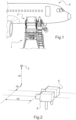
- FIG 1 there is shown an example of an airport vehicle 1 which is a container loader, being docked at a docking area 2, which is a gate 2, of an aircraft 5 which is an airplane 5.
- the vehicle 1 is equipped with the docking control system of the invention, and moves using rolling means, typically one or more sets of wheels (not shown in the figure 1 ), controlled by steering means allowing the movement of the rolling means to be directed in a given direction.
- rolling means typically one or more sets of wheels (not shown in the figure 1 )
- steering means allowing the movement of the rolling means to be directed in a given direction.
- the rolling means are connected by these steering means to the control system, to allow the vehicle 1 to be guided on the trajectory determined by the control system as will be explained below on an example of embodiment and implementation.
- the rolling means 11, 12 comprise in particular a front axle 12.
- the control system is connected to the rolling means 11, 12 by the steering means so as to allow the vehicle 1 to be guided by controlling this front axle 12.
- the docking zone 2 of the aircraft 5 is equipped with one or more targets 3, 4, in this case two targets 3, 4.
- Such targets 3, 4 can for example be embedded or painted on the fuselage of the aircraft 5.
- the control system of the invention comprises first determination means, which are configured to determine the type of the target(s) 3, 4 from a set of given target types. These determination means are also configured to determine the position of each of the targets 3, 4.
- control system comprises second determination means, which are configured to determine a guidance trajectory of the vehicle 1 towards the docking zone 2, depending on the type and position of the target(s) 3, 4.
- the first determination means are capable of determining the size and/or shape of targets 3, 4, and of comparing this size and/or shape with sizes and/or shapes stored in a database, embedded or remote. These target shapes and sizes are stored in the database in association with target types also stored in that database.
- the first means of determination deduce the type of the given 3, 4 target.
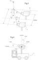
- the first determining means comprise a two-dimensional vision device 6, shown in two examples in the figures 2 And 3 .
- This two-dimensional vision device 6 is capable of determining the size and/or shape of the target 3, 4, according to two first directions dy, dz.
- the first determination means comprise means 7, 8 for determining the distance dx between the first determination means themselves and the target 3, 4, also shown in the two examples of the figures 2 And 3 respectively.
- the means 8 for determining the distance dx comprise a three-dimensional vision device 8 or a distance sensor, which may for example be a laser sensor, an ultrasonic sensor or a radar.
- the distance dx between the first determination means and the target 3, 4 is obtained by triangulation, from the first two-dimensional vision device 6 and a second two-dimensional vision device 7.
- the control system of the invention may also comprise third determination means configured to determine the type of the docking destination 5, whether this docking destination 5 is an airplane 5 or a building. For example, in the case of an airplane 5, these third determination means make it possible to determine the type of the airplane 5, in particular its make, its type in the make, and its version in the type.
- the second determination means are further capable of determining one or more exclusion zones depending on the type of docking destination, in this case the aircraft 5 in our example, to ensure that the guidance trajectory of the vehicle 1 towards the docking zone 2 does not pass through any of these exclusion zones.
- the third determination means determine one or more parameters of at least two main parts of the aircraft 5. This or these parameters may be the size and/or the relative position of these main parts of the aircraft 5.
- the third determining means then compare the value of the parameter(s) with values of these parameters stored in a database, on-board or remote. These parameter values are stored in the database in association with aircraft types 5. Thus, by comparing the determined parameter values with the parameter values stored in the database, the third determining means deduce the type of the aircraft 5.
- the shape of the aircraft 5 can be analyzed. From this analysis, the relative position and size of certain major parts of the aircraft 5 (such as engines, wings, doors) are deduced, which are compared to the values stored in the database.
- certain major parts of the aircraft 5 such as engines, wings, doors
- the type selected in the database will be the one for which the number of measured information, compared with the values stored in the database for the type in question, is maximum.
- the type of aircraft 5 may be obtained via an RFID type tag read by a suitable reader (or by any other wireless communication means appropriate to the tag type).
- an aircraft identifier 5 allows an operator to directly know the model and type of aircraft 5, information which can then be entered by the operator into the system.
- Exclusion zones may also depend on the sequence of ground operations, in order to optimize trajectory definition and avoid interference with other equipment or devices involved in ground support to the aircraft 5.
- the determination means presented above can be used to automatically recognize the type and position of the devices and equipment involved, which will be compared with the information relating to the gate at which the docking is to take place.
- the type of equipment and devices in question can also be determined by reading an RFID-type marker (or other type of marker readable remotely by wireless reading means).
- a predefined ground operation sequence can be used.
- the sequence is already defined, and a new aircraft or equipment arriving in the area knows that other aircraft are in the area, based on its position in the time sequence of operations.
- This predefined operation sequence is stored, for example, in the vehicle, in a ground operation sequence database.
- means may be provided for increasing the viewing angle of the first determination means, in particular the two-dimensional vision device 6.
- the two-dimensional vision device 6, just like the means 7, 8 for determining the distance dx between the first determination means themselves and the target 3, 4, are mounted on the vehicle 1 by means of a mobile mechanism rotating in at least two perpendicular planes, oriented in the direction of the door 2 of the aircraft 5.
- the position of this device 6 is adjusted in real time to target the middle of the two targets 3, 4.
- the position of the device 6 relative to the vehicle 1 is also measured to determine the relative position of the aircraft 5 relative to the vehicle 1.
- the two-dimensional vision device 6 can be combined with another two-dimensional vision device 9.
- the distance between the two devices 6 and 9 is determined, and the respective fields of view 18 and 19 of the two devices 6 and 9 are combined into an extended field of view 20.
- the angle between the vehicle 1 and the docking line 10 is not limited to the field of vision of the two-dimensional vision device 6 alone. This makes it possible to increase the capacity of the system of the invention by making it, for example, capable of introducing tight turns into the determined guidance trajectory.
- the second determination means are capable of determining a docking line 10.
- This docking line 10 is the line passing through the target point 13 located at an equal distance from the two targets 3, 4 on the surface of the docking zone 2 and perpendicular to this surface.
- the vehicle guidance trajectory 1 towards the docking zone 2 calculated by the system of the invention is then determined so that it ends with a final portion of the docking line 10.
- the length of this final portion is greater than or equal to a determined threshold, preferably greater than or equal to 2 meters. This ensures that the vehicle 1 guided by the system of the invention reaches the docking line 10 at least two meters before the fuselage of the aircraft 5.
- a driver can, for example, take over to manually drive the vehicle to the docking zone 2 at very low speed.
- the second determining means are capable of determining the trajectory for reaching the final portion of the docking line 10, by adjusting this trajectory at different determined moments.
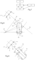
- the system switches to state B and checks whether the vehicle 1 is located at a distance greater than a given distance from the docking line 10. If this is the case, the second determination means adjust the trajectory in order to align the vehicle 1 with the docking line 10, i.e. to align the rear axle 11 of the vehicle 1 with the docking line 10.
- This operation of adjusting the trajectory in order to align the vehicle 1 with the docking line 10 is repeated at intervals, as long as the vehicle 1 is at a distance greater than a given distance from the docking line 10.
- a target point 15 is determined on the docking line 10, and a trajectory 16 allowing the vehicle 1 to reach the target point 15 is determined.
- This target point 15 therefore corresponds to the target point of the docking line 10 at which the vehicle 1 seeks to intercept this docking line 10.
- the determination of the target point 15 is a function of the longitudinal distance between the vehicle 1 and the docking zone 2, the lateral distance between the vehicle 1 and the docking line 10, and the angle ⁇ between the longitudinal axis L of the vehicle 1 and the docking line 10.
- the lateral distance between the vehicle 1 and the docking line 10 is measured from the center 14 of the rear axle 11 of the vehicle 1.
- the longitudinal distance between the vehicle 1 and the docking zone 2 is measured from the center 14 of the rear axle 11 of the vehicle 1.
- the trajectory 16 to allow the vehicle 1 to reach the target point 15 forms an arc of a circle 16.
- This arc of a circle 16 starts from the center 14 of the rear axle 11 of the vehicle 1, and goes to the target point 15.
- the radius of this arc of a circle 16 is determined by the formula (X 2 + Y 2 ) / (2 ⁇ Y), in which X and Y correspond to the coordinates of the target point 15 relative to the center 14 of the rear axle 11 of the vehicle 1.
- the wheels of the front axle 12 are oriented with the axis perpendicular to the direction of each of these wheels and passing through the center of these wheels, passes through the center 21 of the circle which supports the arc-shaped trajectory 16.
- the system switches to state C shown in the figure 7 .
- the second determination means then seek to align the vehicle 1 more finely with the docking line 10, that is to say to align the front axle 12 of the vehicle 1 with the docking line 10.
- the second determining means orient the wheels of the front axle 12 of the vehicle 1 according to an angle which depends on the distance between the center 17 of this front axle 12 and the docking line 10.
- the system can switch to state D, called “dark mode”, when the confidence level in the location of targets 3, 4, determined by the first determination means, is below a given threshold, or when the first determination means no longer detect targets 3, 4.
- the second determination means decide to maintain the trajectory determined at the previous moment.
- the position of the targets can then be estimated by measuring the vehicle's trajectory using an odometer and the angle of the front wheels. The vehicle's trajectory is then recalculated relative to the estimated target position.
- the second determination means proceed to an adjustment of the trajectory of the vehicle 1 to reach the docking line.
- the system checks whether the level of confidence in the location of targets 3, 4, determined by the first determination means, is greater than a given threshold, and whether the first determination means still detect targets 3, 4. If this is not the case, the second determination means retain the trajectory determined at the previous moment without adjusting it.
- the system of the invention comprises means for measuring the distance between the tool in question and the docking zone 2, and its height relative to the docking zone. This measurement may in particular be obtained by triangulation from the location of the targets 3, 4, by means of the devices 6, 7, 8 presented above relative to the first determination means.
- the position of the tool can thus be automatically adjusted.
- the system of the invention is an electronic system intended to be embedded in the vehicle 1, comprising one or more information storage memories for storing the information, and one or more units for processing this information, allowing the implementation of the functions of the first, second and third determination means.
- the embodiments presented above concern the determination, by the second determination means, of the guidance trajectory of the vehicle 1 towards the docking zone 2 as a function of the position of the docking zone 2 determined by the first determination means, by determining the type and position of one or more targets 3, 4 associated with the docking zone 2.
- the second determination means measure the alignment between the vehicle 1 and the docking zone 2 by analyzing at least part of the profile of the docking destination 5, that is to say, in the case of an aircraft 5, the fuselage line of this aircraft 5.
- the target point 13, located on the surface of the docking zone 2, from which the docking line 10 extends perpendicular to this surface of the docking zone 2 is then determined according to the type of the berthing destination 5 and/or berthing zone 2 determined by said analysis, or possibly by the third means of determination presented above.
- the first determination means can then determine a three-dimensional representation of the docking destination 5 and carry out one or more measurements in this three-dimensional representation to determine this position of the docking zone 2.
- a measurement database can be used and the measurements made can be compared with the measurements stored in this database, to determine the outline of the docking zone 2 and its position relative to one or more other zones of the docking destination 5.
- system of the invention is not limited to controlling the docking of an airport vehicle at the door of an aircraft such as an airplane, but extends to controlling the docking of any type of vehicle to any type of aircraft, or even to any other vehicle or any building.
Landscapes
- Engineering & Computer Science (AREA)
- Radar, Positioning & Navigation (AREA)
- Remote Sensing (AREA)
- Physics & Mathematics (AREA)
- Aviation & Aerospace Engineering (AREA)
- General Physics & Mathematics (AREA)
- Automation & Control Theory (AREA)
- Mechanical Engineering (AREA)
- Transportation (AREA)
- Electromagnetism (AREA)
- Computer Networks & Wireless Communication (AREA)
- Computer Vision & Pattern Recognition (AREA)
- Traffic Control Systems (AREA)
- Multimedia (AREA)
- Control Of Position, Course, Altitude, Or Attitude Of Moving Bodies (AREA)
Claims (26)
- Elektronisches Andocksystem zur Steuerung des Andockens eines Fahrzeugs (1), wie eines Flughafenfahrzeugs (1), an eine gegebene Andockzone (2) eines Andockziels (5) eines Luftfahrzeugs (5) oder eines Gebäudes, wobei die gegebene Andockzone (2) mindestens ein Zielobjekt (3, 4) umfasst, wobei das System umfasst:erste Bestimmungsmittel, die konfiguriert sind, die Position der Andockzone (2) durch Bestimmung des Typs des Zielobjekts (3, 4) aus einer gegebenen Menge von Typen und dessen Position zu bestimmen,zweite Bestimmungsmittel, die konfiguriert sind, eine Führungsbahn des Fahrzeugs (1) zur genannten gegebenen Andockzone (2) in Abhängigkeit vom Typ und der Position des genannten Zielobjekts (3, 4) zu bestimmen,dritte Bestimmungsmittel, die konfiguriert sind, den Typ des Andockziels (5) zu bestimmen,wobei die zweiten Bestimmungsmittel in der Lage sind, eine oder mehrere Ausschlusszonen in Abhängigkeit vom Typ des Andockziels (5) durch Vergleich des Typs des Andockziels (5) mit in einer Datenbank gespeicherten Andockzieltypen, die mit Ausschlusszonen verknüpft sind, zu bestimmen, sodass die Führungsbahn des Fahrzeugs (1) zur gegebenen Andockzone (2) in keiner der genannten Ausschlusszonen verläuft,dadurch gekennzeichnet, dass die zweiten Bestimmungsmittel in der Lage sind, eine Andocklinie (10) zu bestimmen, die durch einen Punkt (13) verläuft, der sich auf der Oberfläche der Andockzone (2) befindet und senkrecht zu dieser Oberfläche ist, sodass die Führungsbahn des Fahrzeugs (1) zur Andockzone (2) in einem letzten Abschnitt der genannten Andocklinie (10) endet, wobei diese eine Länge hat, die größer oder gleich einem bestimmten Schwellenwert ist, vorzugsweise mindestens 2 Meter,wobei die zweiten Bestimmungsmittel in der Lage sind, die Führungsbahn zu verschiedenen bestimmten Zeitpunkten anzupassen, um zu jedem dieser Zeitpunkte:- das Hinterrad (11) des Fahrzeugs (1) mit der Andocklinie (10) auszurichten, falls sich das genannte Fahrzeug (1) in einer Entfernung zur Andocklinie (10) befindet, die größer ist als eine vorgegebene Entfernung,- das Vorderrad (12) des Fahrzeugs (1) mit der Andocklinie (10) auszurichten, falls sich das genannte Fahrzeug (1) in einer Entfernung zur Andocklinie (10) befindet, die kleiner ist als die vorgegebene Entfernung,- die zuvor bestimmte Führungsbahn beizubehalten, falls das Vertrauen in die Lokalisierung der Zielobjekte (3, 4), das durch die ersten Bestimmungsmittel bestimmt wurde, unter einem gegebenen Schwellenwert liegt oder falls die ersten Bestimmungsmittel die Zielobjekte (3, 4) nicht mehr erkennen.
- System nach Anspruch 1, wobei die gegebene Andockzone (2) eine Andockzone eines Andockziels (5) eines Luftfahrzeugs (5) oder eines Gebäudes ist, dadurch gekennzeichnet, dass die ersten Bestimmungsmittel in der Lage sind, eine dreidimensionale Darstellung des Andockziels (5) zu bestimmen und eine oder mehrere Messungen in der genannten dreidimensionalen Darstellung durchzuführen, um die Position der Andockzone (2) zu bestimmen.
- System nach Anspruch 2, dadurch gekennzeichnet, dass die ersten Bestimmungsmittel in der Lage sind, die Messungen mit in einer Datenbank gespeicherten Messungen zu vergleichen, um daraus die Kontur der Andockzone (2) und deren Position relativ zu mindestens einer anderen Zone des Andockziels (5) abzuleiten.
- System nach einem der Ansprüche 1 bis 3, dadurch gekennzeichnet, dass die ersten Bestimmungsmittel in der Lage sind, die Größe und/oder die Form des Zielobjekts (3, 4) zu bestimmen und die ermittelte Größe und/oder Form mit in einer Datenbank gespeicherten Größen und/oder Formen zu vergleichen, die in Verbindung mit ebenfalls in der Datenbank gespeicherten Zielobjekttypen gespeichert sind, um daraus den Typ des Zielobjekts (3, 4) abzuleiten.
- System nach Anspruch 4, dadurch gekennzeichnet, dass die ersten Bestimmungsmittel ein zweidimensionales Vision-Gerät (6) umfassen, das in der Lage ist, die Größe und/oder die Form des Zielobjekts (3, 4) zu bestimmen, sowie Mittel (7, 8) zur Bestimmung des Abstands zwischen den ersten Bestimmungsmitteln und dem Zielobjekt (3, 4).
- System nach Anspruch 5, dadurch gekennzeichnet, dass die Mittel (7) zur Bestimmung des Abstands ein dreidimensionales Vision-Gerät (7) oder einen Abstandssensor, wie einen Lasersensor, Ultraschallsensor oder Radarsensor, umfassen.
- System nach einem der Ansprüche 1 bis 6, wobei die gegebene Andockzone (2) eine Andockzone eines Andockziels (5) eines Luftfahrzeugs (5) oder eines Gebäudes ist, dadurch gekennzeichnet, dass es dritte Bestimmungsmittel umfasst, die konfiguriert sind, um den Typ des Andockziels (5) und/oder den Typ der Andockzone (2) zu bestimmen.
- System nach einem der Ansprüche 1 bis 7, dadurch gekennzeichnet, dass die zweiten Bestimmungsmittel in der Lage sind, die Ausrichtung zwischen dem Fahrzeug (1) und der Andockzone (2) durch Analyse von mindestens einem Teil des Profils des Andockziels (5), wie der Rumpflinie des Luftfahrzeugs (5), in der Nähe des Zielobjekts (3, 4) zu messen und den Punkt (13) in Abhängigkeit vom Typ des Andockziels (5) und/oder der Andockzone (2) zu bestimmen.
- System nach einem der Ansprüche 1 bis 8, wobei die gegebene Andockzone (2) mindestens zwei Zielobjekte (3, 4) umfasst, dadurch gekennzeichnet, dass der Punkt (13) in gleichem Abstand zu den genannten Zielobjekten (3, 4) liegt.
- System nach einem der Ansprüche 1 bis 9, dadurch gekennzeichnet, dass die zweiten Bestimmungsmittel in der Lage sind, die Führungsbahn zu jedem der bestimmten Zeitpunkte anzupassen und, falls sich das Fahrzeug (1) in einer Entfernung zur Andocklinie befindet, die größer ist als die vorgegebene Entfernung, indem sie:- einen Zielpunkt (15) auf der Andocklinie (10) bestimmen- eine Führungsbahn (16) definieren, die es dem Fahrzeug (1) ermöglicht, den Zielpunkt (15) zu erreichen.
- System nach Anspruch 10, dadurch gekennzeichnet, dass die Bestimmung des Zielpunkts (15) in Abhängigkeit vom longitudinalen Abstand zwischen dem Fahrzeug (1) und der Andockzone (2), dem seitlichen Abstand zwischen dem Fahrzeug (1) und der Andocklinie (10) sowie dem Winkel (α) zwischen der Längsachse (L) des Fahrzeugs (1) und der Andocklinie (10) erfolgt.
- System nach Anspruch 11, dadurch gekennzeichnet, dass die Führungsbahn (16), die es dem Fahrzeug (1) ermöglicht, den Zielpunkt (15) zu erreichen, einen Kreisbogen (16) bildet, der vom Zentrum (14) des Hinterrads (11) des Fahrzeugs (1) zum Zielpunkt (15) verläuft und dessen Radius durch die Formel (X2 + Y2) / (2 × Y) bestimmt wird, wobei X und Y den Koordinaten des Zielpunkts (15) relativ zum Zentrum (14) des Hinterrads (11) des Fahrzeugs (1) entsprechen.
- System nach einem der Ansprüche 1 bis 12, dadurch gekennzeichnet, dass die zweiten Bestimmungsmittel in der Lage sind, die Führungsbahn zu jedem der bestimmten Zeitpunkte anzupassen, und im Falle, dass sich das Fahrzeug (1) in einer Entfernung zur Andocklinie (10) befindet, die kleiner als die vorgegebene Entfernung ist, die Räder des Vorderrads (12) des Fahrzeugs (1) in einem Winkel auszurichten, der von der Entfernung zwischen dem Zentrum (17) des genannten Vorderrads (12) und der Andocklinie (10) abhängt.
- Fahrzeug (1), wie ein Flughafenfahrzeug, umfassend Fahrmittel (11, 12), die es ermöglichen, das Fahrzeug (1) durch Rollen in Bewegung zu setzen, Steuerungsmittel, die es ermöglichen, die Bewegung in eine bestimmte Richtung zu lenken, und ein elektronisches Andocksystem nach einem der Ansprüche 1 bis 13, wobei die Fahrmittel (11, 12) über die Steuerungsmittel mit dem Steuersystem verbunden sind, um die Führung des Fahrzeugs (1) auf der von den zweiten Bestimmungsmitteln des genannten Steuersystems bestimmten Führungsbahn zu ermöglichen.
- Fahrzeug (1) nach Anspruch 14, dadurch gekennzeichnet, dass die Fahrmittel (11, 12) ein Vorderrad (12) umfassen und dass das Steuersystem über die Steuerungsmittel mit den Fahrmitteln (11, 12) verbunden ist, um die Führung des Fahrzeugs (1) durch Steuerung des Vorderrads (12) zu ermöglichen.
- Verfahren zur Steuerung des Andockens eines Fahrzeugs (1), wie eines Flughafenfahrzeugs (1), an eine gegebene Andockzone (2) eines Andockziels (5) eines Luftfahrzeugs (5) oder eines Gebäudes, wobei die gegebene Andockzone (2) mindestens ein Zielobjekt (3, 4) umfasst, umfassend einen ersten Schritt zur Bestimmung der Position der Andockzone (2) durch Bestimmung des Typs des Zielobjekts (3, 4) aus einer gegebenen Menge von Typen und dessen Position, einen zweiten Schritt zur Bestimmung einer Führungsbahn des Fahrzeugs (1) zur Andockzone (2) in Abhängigkeit vom Typ und der Position des genannten Zielobjekts (3, 4), und einen dritten Schritt zur Bestimmung des Typs des Andockziels (5), wobei der zweite Bestimmungsschritt die Bestimmung einer oder mehrerer Ausschlusszonen in Abhängigkeit vom Typ des Andockziels (5) umfasst, durch Vergleich des Typs des Andockziels (5) mit in einer Datenbank gespeicherten Andockzieltypen, die mit Ausschlusszonen verknüpft sind, sodass die Führungsbahn des Fahrzeugs (1) zur gegebenen Andockzone (2) in keiner der genannten Ausschlusszonen verläuft,
dadurch gekennzeichnet, dass im Laufe des zweiten Bestimmungsschritts eine Andocklinie (10) bestimmt wird, die durch einen Punkt (13) verläuft, der sich auf der Oberfläche der Andockzone (2) befindet und senkrecht zu dieser Oberfläche ist, sodass die Führungsbahn des Fahrzeugs (1) zur Andockzone (2) in einem letzten Abschnitt der genannten Andocklinie (10) endet, mit einer Länge, die größer oder gleich einem bestimmten Schwellenwert ist, vorzugsweise mindestens 2 Meter, und dass während des zweiten Bestimmungsschritts die Führungsbahn zur Erreichung des letzten Abschnitts der Andocklinie (10) durch Anpassung der genannten Führungsbahn zu verschiedenen bestimmten Zeitpunkten bestimmt wird, um zu jedem der genannten Zeitpunkte:- das Hinterrad (11) des Fahrzeugs (1) mit der Andocklinie (10) auszurichten, falls sich das genannte Fahrzeug (1) in einer Entfernung zur Andocklinie (10) befindet, die größer als eine vorgegebene Entfernung ist;- das Vorderrad (12) des Fahrzeugs (1) mit der Andocklinie (10) auszurichten, falls sich das genannte Fahrzeug (1) in einer Entfernung zur Andocklinie (10) befindet, die kleiner als die vorgegebene Entfernung ist;- die zuvor bestimmte Führungsbahn beizubehalten, falls das Vertrauen in die Lokalisierung der Zielobjekte (3, 4) während des ersten Bestimmungsschritts unter einem bestimmten Schwellenwert liegt oder falls die Zielobjekte (3, 4) nicht mehr erkannt werden. - Verfahren nach Anspruch 16, wobei die gegebene Andockzone (2) eine Andockzone eines Andockziels (5) ist, dadurch gekennzeichnet, dass im Laufe des ersten Bestimmungsschritts eine dreidimensionale Darstellung des Andockziels (5) bestimmt wird und eine oder mehrere Messungen in der genannten dreidimensionalen Darstellung durchgeführt werden, um die Position der Andockzone zu bestimmen.
- Verfahren nach Anspruch 17, dadurch gekennzeichnet, dass im Laufe des ersten Bestimmungsschritts die Messungen mit in einer Datenbank gespeicherten Messungen verglichen werden, um daraus die Kontur der Andockzone (2) und deren Position relativ zu mindestens einer anderen Zone des Andockziels (5) abzuleiten.
- Verfahren nach einem der Ansprüche 16 bis 18, dadurch gekennzeichnet, dass im Laufe des ersten Bestimmungsschritts die Größe und/oder die Form des Zielobjekts (3, 4) bestimmt wird und die bestimmte Größe und/oder Form mit in einer Datenbank gespeicherten Größen und/oder Formen verglichen wird, die in Verbindung mit ebenfalls in der Datenbank gespeicherten Zielobjekttypen gespeichert sind, um daraus den Typ des Zielobjekts (3, 4) abzuleiten.
- Verfahren nach einem der Ansprüche 16 bis 19, dadurch gekennzeichnet, dass im Laufe des zweiten Bestimmungsschritts die Ausrichtung zwischen dem Fahrzeug (1) und der Andockzone (2) durch Analyse von mindestens einem Teil des Profils des Andockziels (5), wie der Rumpflinie des Luftfahrzeugs (5), in der Nähe des Zielobjekts (3, 4) gemessen wird.
- Verfahren nach einem der Ansprüche 16 bis 20, wobei die Andockzone (2) mindestens zwei Zielobjekte (3, 4) umfasst, dadurch gekennzeichnet, dass der Zielpunkt (13) in gleichem Abstand zu den genannten Zielobjekten (3, 4) liegt.
- Verfahren nach einem der Ansprüche 16 bis 21, dadurch gekennzeichnet, dass im Laufe des zweiten Bestimmungsschritts die Führungsbahn zur Erreichung des letzten Abschnitts der Andocklinie (10) durch Anpassung der genannten Führungsbahn zu verschiedenen bestimmten Zeitpunkten bestimmt wird, um zu jedem der genannten Zeitpunkte:- das Hinterrad (11) des Fahrzeugs (1) mit der Andocklinie (10) auszurichten, falls sich das genannte Fahrzeug (1) in einer Entfernung zur Andocklinie (10) befindet, die größer als eine vorgegebene Entfernung ist;- das Vorderrad (12) des Fahrzeugs (1) mit der Andocklinie (10) auszurichten, falls sich das genannte Fahrzeug (1) in einer Entfernung zur Andocklinie (10) befindet, die kleiner als die vorgegebene Entfernung ist;- die zuvor bestimmte Führungsbahn beizubehalten, falls das Vertrauen in die Lokalisierung der Zielobjekte (3, 4) während des ersten Bestimmungsschritts unter einem bestimmten Schwellenwert liegt oder falls die Zielobjekte (3, 4) nicht mehr erkannt werden.
- Verfahren nach einem der Ansprüche 16 bis 22, dadurch gekennzeichnet, dass im Laufe des zweiten Bestimmungsschritts, zu jedem der bestimmten Zeitpunkte und im Fall, dass sich das Fahrzeug (1) in einer Entfernung zur Andocklinie (10) befindet, die größer als die vorgegebene Entfernung ist, die Führungsbahn angepasst wird durch:- Bestimmen eines Zielpunkts (15) auf der Andocklinie (10);- Definieren einer Führungsbahn (16), die es dem Fahrzeug (1) ermöglicht, den Zielpunkt (15) zu erreichen.
- Verfahren nach Anspruch 23, dadurch gekennzeichnet, dass die Bestimmung des Zielpunkts (15) in Abhängigkeit vom longitudinalen Abstand zwischen dem Fahrzeug (1) und der Andockzone (2), dem seitlichen Abstand zwischen dem Fahrzeug (1) und der Andocklinie (10) sowie dem Winkel (α) zwischen der Längsachse (L) des Fahrzeugs (1) und der Andocklinie (10) erfolgt.
- Verfahren nach einem der Ansprüche 23 bis 24, dadurch gekennzeichnet, dass die Führungsbahn (16), die es dem Fahrzeug (1) ermöglicht, den Zielpunkt (15) zu erreichen, einen Kreisbogen (16) bildet, der vom Zentrum (14) des Hinterrads (11) des Fahrzeugs (1) zum Zielpunkt (15) verläuft und dessen Radius durch die Formel (X^2 + Y^2) / (2 × Y) bestimmt wird, wobei X und Y den Koordinaten des Zielpunkts (15) relativ zum Zentrum (14) des Hinterrads (11) des Fahrzeugs (1) entsprechen.
- Verfahren nach einem der Ansprüche 16 bis 25, dadurch gekennzeichnet, dass im Laufe des zweiten Bestimmungsschritts, zu jedem der bestimmten Zeitpunkte und im Fall, dass sich das Fahrzeug (1) in einer Entfernung zur Andocklinie (10) befindet, die kleiner als die vorgegebene Entfernung ist, die Führungsbahn durch Ausrichten der Räder des Vorderrads (12) des Fahrzeugs (1) in einem Winkel angepasst wird, der von der Entfernung zwischen dem Zentrum (17) des genannten Vorderrads (12) und der Andocklinie (10) abhängt.
Applications Claiming Priority (1)
| Application Number | Priority Date | Filing Date | Title |
|---|---|---|---|
| PCT/FR2018/052059 WO2020030857A1 (fr) | 2018-08-10 | 2018-08-10 | Systeme electronique de contrôle de l'accostage d'un vehicule a une zone d'accostage, et procede correspondant |
Publications (3)
| Publication Number | Publication Date |
|---|---|
| EP3834010A1 EP3834010A1 (de) | 2021-06-16 |
| EP3834010B1 true EP3834010B1 (de) | 2024-12-11 |
| EP3834010C0 EP3834010C0 (de) | 2024-12-11 |
Family
ID=63686010
Family Applications (1)
| Application Number | Title | Priority Date | Filing Date |
|---|---|---|---|
| EP18778958.1A Active EP3834010B1 (de) | 2018-08-10 | 2018-08-10 | Elektronisches system zur steuerung des andockens eines fahrzeugs mit einem andockbereich und zugehöriges verfahren |
Country Status (3)
| Country | Link |
|---|---|
| US (1) | US11932418B2 (de) |
| EP (1) | EP3834010B1 (de) |
| WO (1) | WO2020030857A1 (de) |
Families Citing this family (3)
| Publication number | Priority date | Publication date | Assignee | Title |
|---|---|---|---|---|
| WO2021064443A1 (en) * | 2019-09-30 | 2021-04-08 | Power Stow International Aps | Airport vehicle having an anti-collision system and method for operating a vehicle having an anti-collision system |
| US12420935B2 (en) * | 2022-11-30 | 2025-09-23 | The Boeing Company | Aircraft ice detection |
| CN119882760B (zh) * | 2023-10-23 | 2025-10-28 | 广东汇天航空航天科技有限公司 | 飞行汽车的自动对齐方法、装置、路行车辆及飞行汽车 |
Family Cites Families (11)
| Publication number | Priority date | Publication date | Assignee | Title |
|---|---|---|---|---|
| US5170352A (en) * | 1990-05-07 | 1992-12-08 | Fmc Corporation | Multi-purpose autonomous vehicle with path plotting |
| FR2830239B1 (fr) | 2001-09-28 | 2004-02-06 | Tld Europ | Dispositif de controle de couple du systeme de prehension d'un tracteur d'avion |
| CA2373669A1 (en) * | 2002-02-27 | 2003-08-27 | Indal Technologies Inc. | Imaging system for a passenger bridge of the like for docking automatically with an aircraft |
| EP1464577A1 (de) | 2003-04-03 | 2004-10-06 | TLD Europe SA | Drehmomentsteuerung einer Greifvorrichtung eines Schleppfahrzeugs für Flugzeuge |
| FR2956381B1 (fr) | 2010-02-16 | 2012-04-20 | Tld Europ | Tracteur d'avion. |
| KR101685045B1 (ko) | 2010-02-16 | 2016-12-09 | 이스라엘 에어로스페이스 인더스트리즈 리미티드 | 항공기 트랙터 |
| GB201305834D0 (en) | 2013-03-29 | 2013-05-15 | Mallaghan Engineering Ltd | Collision prevention system for ground support equipment |
| FR3017368B1 (fr) | 2014-02-07 | 2016-02-05 | Tld Europ | Vehicule aeroportuaire pour aeronef a consignation de donnees sur impact |
| FR3017848B1 (fr) | 2014-02-25 | 2017-07-14 | Tld Europe | Procede de limitation de vitesse pour vehicule aeroportuaire |
| DE102017201037A1 (de) * | 2016-02-10 | 2017-08-10 | pmdtechnologies ag | Dockingsystem für Fahrzeuge mit einer 3D-Kamera und Verfahren zum Betreiben eines solchen Systems |
| US9746846B1 (en) * | 2016-09-09 | 2017-08-29 | Accenture Global Solutions Limited | Automated loading bridge positioning using encoded decals |
-
2018
- 2018-08-10 EP EP18778958.1A patent/EP3834010B1/de active Active
- 2018-08-10 WO PCT/FR2018/052059 patent/WO2020030857A1/fr not_active Ceased
- 2018-08-10 US US17/267,581 patent/US11932418B2/en active Active
Also Published As
| Publication number | Publication date |
|---|---|
| US20210309387A1 (en) | 2021-10-07 |
| US11932418B2 (en) | 2024-03-19 |
| WO2020030857A1 (fr) | 2020-02-13 |
| EP3834010C0 (de) | 2024-12-11 |
| EP3834010A1 (de) | 2021-06-16 |
Similar Documents
| Publication | Publication Date | Title |
|---|---|---|
| EP3152097B1 (de) | Parkhilfesystem vorrichtung und fahrzeug mit einer derartigen vorrichtung | |
| US11829151B2 (en) | Construction-vehicle autonomous travel control device | |
| US9395192B1 (en) | Methods and systems for road and lane boundary tracing | |
| CN103562745B (zh) | 用于定位车辆的技术 | |
| US11008201B2 (en) | Automated rolling-jack for drive-on lifts | |
| CN111175788B (zh) | 自动驾驶车辆横向定位方法及其定位系统 | |
| WO1997047945A1 (fr) | Procede pour l'evitement lateral par un vehicule d'une zone mobile | |
| EP1459978B1 (de) | Verfahren und Vorrichtung zum Bestimmen eines Endanflugpfades eines Flugzeuges für einen Nicht-Präzisions-Landeanflug eines Flugzeuges | |
| WO2020030857A1 (fr) | Systeme electronique de contrôle de l'accostage d'un vehicule a une zone d'accostage, et procede correspondant | |
| FR2965535A1 (fr) | Procede et dispositif pour effectuer une manoeuvre de stationnement avec un vehicule | |
| EP4294688B1 (de) | Verfahren zum aktivieren eines hindernisvermeidungssystems für ein kraftfahrzeug | |
| FR3028084A1 (fr) | Procede et dispositif de guidage d'un aeronef | |
| EP2480483B1 (de) | Verfahren zur relativen positionierung von landfahrzeugen bezüglich eines krans | |
| EP3115280A1 (de) | Automatisches steuerungsverfahren für das ein- und ausfahren eines fahrzeugs in eine aufnahmestation, und steuerungsvorrichtung für die umsetzung dieses verfahrens | |
| CA2913997A1 (fr) | Procede de discrimination de la presence d'un vehicule ferroviaire sur un canton, procede de calcul d'un intervalle de securite et dispositif associe | |
| EP2962928B1 (de) | Marineplattform | |
| EP3734392B1 (de) | Verfahren zum führen eines autonomen fahrzeugs | |
| WO2016045703A1 (fr) | Procédé et dispositif de détermination du risque de collision au sol d'un avion | |
| WO2022091017A1 (fr) | Système intégré de diagnostic et de maintenance de véhicules et de leur gestion dans un atelier de réparation de véhicules | |
| EP4371892B1 (de) | Unbemanntes luftfahrzeug mit zwei radaren | |
| FR3028085A1 (fr) | Procede et dispositif de guidage relatif d'un aeronef | |
| EP3359927B1 (de) | Mobile vorrichtung zur steuerung und/oder wartung von zumindest einem anlagenteil einer flughafenzone, system und dazugehöriges verfahren | |
| FR3082830A1 (fr) | Systeme aeroportuaire anticollision | |
| WO2016096757A1 (fr) | Procédé et système d'estimation d'un indicateur de glissance d'une piste d'un aéroport | |
| FR3131889A1 (fr) | Procédé de contrôle d’un système d’aide à la conduite d’un véhicule circulant sur une voie de circulation |
Legal Events
| Date | Code | Title | Description |
|---|---|---|---|
| STAA | Information on the status of an ep patent application or granted ep patent |
Free format text: STATUS: UNKNOWN |
|
| STAA | Information on the status of an ep patent application or granted ep patent |
Free format text: STATUS: THE INTERNATIONAL PUBLICATION HAS BEEN MADE |
|
| PUAI | Public reference made under article 153(3) epc to a published international application that has entered the european phase |
Free format text: ORIGINAL CODE: 0009012 |
|
| STAA | Information on the status of an ep patent application or granted ep patent |
Free format text: STATUS: REQUEST FOR EXAMINATION WAS MADE |
|
| 17P | Request for examination filed |
Effective date: 20210302 |
|
| AK | Designated contracting states |
Kind code of ref document: A1 Designated state(s): AL AT BE BG CH CY CZ DE DK EE ES FI FR GB GR HR HU IE IS IT LI LT LU LV MC MK MT NL NO PL PT RO RS SE SI SK SM TR |
|
| DAV | Request for validation of the european patent (deleted) | ||
| DAX | Request for extension of the european patent (deleted) | ||
| STAA | Information on the status of an ep patent application or granted ep patent |
Free format text: STATUS: EXAMINATION IS IN PROGRESS |
|
| 17Q | First examination report despatched |
Effective date: 20230301 |
|
| GRAP | Despatch of communication of intention to grant a patent |
Free format text: ORIGINAL CODE: EPIDOSNIGR1 |
|
| STAA | Information on the status of an ep patent application or granted ep patent |
Free format text: STATUS: GRANT OF PATENT IS INTENDED |
|
| INTG | Intention to grant announced |
Effective date: 20240805 |
|
| GRAS | Grant fee paid |
Free format text: ORIGINAL CODE: EPIDOSNIGR3 |
|
| GRAA | (expected) grant |
Free format text: ORIGINAL CODE: 0009210 |
|
| STAA | Information on the status of an ep patent application or granted ep patent |
Free format text: STATUS: THE PATENT HAS BEEN GRANTED |
|
| AK | Designated contracting states |
Kind code of ref document: B1 Designated state(s): AL AT BE BG CH CY CZ DE DK EE ES FI FR GB GR HR HU IE IS IT LI LT LU LV MC MK MT NL NO PL PT RO RS SE SI SK SM TR |
|
| REG | Reference to a national code |
Ref country code: GB Ref legal event code: FG4D Free format text: NOT ENGLISH |
|
| REG | Reference to a national code |
Ref country code: CH Ref legal event code: EP |
|
| REG | Reference to a national code |
Ref country code: DE Ref legal event code: R096 Ref document number: 602018077523 Country of ref document: DE |
|
| REG | Reference to a national code |
Ref country code: IE Ref legal event code: FG4D Free format text: LANGUAGE OF EP DOCUMENT: FRENCH |
|
| U01 | Request for unitary effect filed |
Effective date: 20250110 |
|
| U07 | Unitary effect registered |
Designated state(s): AT BE BG DE DK EE FI FR IT LT LU LV MT NL PT RO SE SI Effective date: 20250117 |
|
| PG25 | Lapsed in a contracting state [announced via postgrant information from national office to epo] |
Ref country code: HR Free format text: LAPSE BECAUSE OF FAILURE TO SUBMIT A TRANSLATION OF THE DESCRIPTION OR TO PAY THE FEE WITHIN THE PRESCRIBED TIME-LIMIT Effective date: 20241211 |
|
| PG25 | Lapsed in a contracting state [announced via postgrant information from national office to epo] |
Ref country code: ES Free format text: LAPSE BECAUSE OF FAILURE TO SUBMIT A TRANSLATION OF THE DESCRIPTION OR TO PAY THE FEE WITHIN THE PRESCRIBED TIME-LIMIT Effective date: 20241211 |
|
| PG25 | Lapsed in a contracting state [announced via postgrant information from national office to epo] |
Ref country code: NO Free format text: LAPSE BECAUSE OF FAILURE TO SUBMIT A TRANSLATION OF THE DESCRIPTION OR TO PAY THE FEE WITHIN THE PRESCRIBED TIME-LIMIT Effective date: 20250311 |
|
| PG25 | Lapsed in a contracting state [announced via postgrant information from national office to epo] |
Ref country code: GR Free format text: LAPSE BECAUSE OF FAILURE TO SUBMIT A TRANSLATION OF THE DESCRIPTION OR TO PAY THE FEE WITHIN THE PRESCRIBED TIME-LIMIT Effective date: 20250312 |
|
| PG25 | Lapsed in a contracting state [announced via postgrant information from national office to epo] |
Ref country code: RS Free format text: LAPSE BECAUSE OF FAILURE TO SUBMIT A TRANSLATION OF THE DESCRIPTION OR TO PAY THE FEE WITHIN THE PRESCRIBED TIME-LIMIT Effective date: 20250311 |
|
| PG25 | Lapsed in a contracting state [announced via postgrant information from national office to epo] |
Ref country code: SM Free format text: LAPSE BECAUSE OF FAILURE TO SUBMIT A TRANSLATION OF THE DESCRIPTION OR TO PAY THE FEE WITHIN THE PRESCRIBED TIME-LIMIT Effective date: 20241211 |
|
| PG25 | Lapsed in a contracting state [announced via postgrant information from national office to epo] |
Ref country code: PL Free format text: LAPSE BECAUSE OF FAILURE TO SUBMIT A TRANSLATION OF THE DESCRIPTION OR TO PAY THE FEE WITHIN THE PRESCRIBED TIME-LIMIT Effective date: 20241211 |
|
| PG25 | Lapsed in a contracting state [announced via postgrant information from national office to epo] |
Ref country code: IS Free format text: LAPSE BECAUSE OF FAILURE TO SUBMIT A TRANSLATION OF THE DESCRIPTION OR TO PAY THE FEE WITHIN THE PRESCRIBED TIME-LIMIT Effective date: 20250411 |
|
| PG25 | Lapsed in a contracting state [announced via postgrant information from national office to epo] |
Ref country code: SK Free format text: LAPSE BECAUSE OF FAILURE TO SUBMIT A TRANSLATION OF THE DESCRIPTION OR TO PAY THE FEE WITHIN THE PRESCRIBED TIME-LIMIT Effective date: 20241211 |
|
| PG25 | Lapsed in a contracting state [announced via postgrant information from national office to epo] |
Ref country code: CZ Free format text: LAPSE BECAUSE OF FAILURE TO SUBMIT A TRANSLATION OF THE DESCRIPTION OR TO PAY THE FEE WITHIN THE PRESCRIBED TIME-LIMIT Effective date: 20241211 |
|
| U20 | Renewal fee for the european patent with unitary effect paid |
Year of fee payment: 8 Effective date: 20250827 |
|
| PLBE | No opposition filed within time limit |
Free format text: ORIGINAL CODE: 0009261 |
|
| STAA | Information on the status of an ep patent application or granted ep patent |
Free format text: STATUS: NO OPPOSITION FILED WITHIN TIME LIMIT |
|
| REG | Reference to a national code |
Ref country code: CH Ref legal event code: L10 Free format text: ST27 STATUS EVENT CODE: U-0-0-L10-L00 (AS PROVIDED BY THE NATIONAL OFFICE) Effective date: 20251022 |
|
| 26N | No opposition filed |
Effective date: 20250912 |
|
| REG | Reference to a national code |
Ref country code: CH Ref legal event code: H13 Free format text: ST27 STATUS EVENT CODE: U-0-0-H10-H13 (AS PROVIDED BY THE NATIONAL OFFICE) Effective date: 20260324 |
|
| PG25 | Lapsed in a contracting state [announced via postgrant information from national office to epo] |
Ref country code: MC Free format text: LAPSE BECAUSE OF FAILURE TO SUBMIT A TRANSLATION OF THE DESCRIPTION OR TO PAY THE FEE WITHIN THE PRESCRIBED TIME-LIMIT Effective date: 20241211 |
|
| PG25 | Lapsed in a contracting state [announced via postgrant information from national office to epo] |
Ref country code: CH Free format text: LAPSE BECAUSE OF NON-PAYMENT OF DUE FEES Effective date: 20250831 |
|
| GBPC | Gb: european patent ceased through non-payment of renewal fee |
Effective date: 20250810 |
|
| PG25 | Lapsed in a contracting state [announced via postgrant information from national office to epo] |
Ref country code: GB Free format text: LAPSE BECAUSE OF NON-PAYMENT OF DUE FEES Effective date: 20250810 |
|
| PG25 | Lapsed in a contracting state [announced via postgrant information from national office to epo] |
Ref country code: IE Free format text: LAPSE BECAUSE OF NON-PAYMENT OF DUE FEES Effective date: 20250810 |