EP3833802B1 - Elektrode für eine rakel zum beizen und reinigen von metalloberflächen - Google Patents
Elektrode für eine rakel zum beizen und reinigen von metalloberflächen Download PDFInfo
- Publication number
- EP3833802B1 EP3833802B1 EP19766369.3A EP19766369A EP3833802B1 EP 3833802 B1 EP3833802 B1 EP 3833802B1 EP 19766369 A EP19766369 A EP 19766369A EP 3833802 B1 EP3833802 B1 EP 3833802B1
- Authority
- EP
- European Patent Office
- Prior art keywords
- electrode
- doctor blade
- pad
- metal wire
- electrolytic solution
- Prior art date
- Legal status (The legal status is an assumption and is not a legal conclusion. Google has not performed a legal analysis and makes no representation as to the accuracy of the status listed.)
- Active
Links
Images





Classifications
-
- C—CHEMISTRY; METALLURGY
- C25—ELECTROLYTIC OR ELECTROPHORETIC PROCESSES; APPARATUS THEREFOR
- C25F—PROCESSES FOR THE ELECTROLYTIC REMOVAL OF MATERIALS FROM OBJECTS; APPARATUS THEREFOR
- C25F7/00—Constructional parts, or assemblies thereof, of cells for electrolytic removal of material from objects; Servicing or operating
-
- C—CHEMISTRY; METALLURGY
- C25—ELECTROLYTIC OR ELECTROPHORETIC PROCESSES; APPARATUS THEREFOR
- C25F—PROCESSES FOR THE ELECTROLYTIC REMOVAL OF MATERIALS FROM OBJECTS; APPARATUS THEREFOR
- C25F1/00—Electrolytic cleaning, degreasing, pickling or descaling
- C25F1/02—Pickling; Descaling
- C25F1/04—Pickling; Descaling in solution
Definitions
- the present invention relates to an electrode for an electrolytically acting doctor blade for pickling and cleaning metal surfaces which may be used also to treat curved surfaces, that is, the object of the present disclosure is the conformation of electrodes that may be mounted on a doctor blade, which, by applying the known electrolytic action to pickle or clean a surface by means of an electrolytic solution suitable to the metal surface being treated and to the type of deposit to be removed, allows to perform said treatment on typical planar surfaces or even, when supported in an appropriate deformable doctor blade, on curved surfaces whether they are convex, i.e., with the doctor blade and the electrode having a concavity, or concave, i.e., with the doctor blade and the electrode having a convexity adapted to the curvature of the surface being treated.
- the prior art includes rectilinear doctor blades used for electrolytically pickling the metal surfaces to be treated, which are comprised of a basically rigid body of the doctor blade so as to act on the convex surface in a limited area of the length of the edge of the doctor blade itself, whereby the electrode used turns out to be rigid and not easy to deform.
- rectilinear doctor blades i.e., with rectilinear electrode, when used on concave surfaces to be treated, can operate only by arranging the direction of the edge of the doctor blade parallel to the generatrix of both the concave and the convex curved surface.
- this electrolytic pickling operation is performed for the external cleaning, i.e., the convex cylindrical surface, or the internal one, i.e., the concave cylindrical surface, of tanks, reservoirs, containers and the like for liquids of a variety of food and nonfood stuff, where said surfaces require a careful removal of deposits, dirt, internal, as well as external scales or patinas, which with use are formed on the metal surface of the tanks, reservoirs and containers themselves.
- Doctor blades are known from JP2009289534 , JP2005022361 , US 2015/014173 , US5662041 , US5408926 , JP2008127729 , US 2012/006691 , US4609450 .
- the aforementioned doctor blades are used by connecting the body of the doctor blade, i.e., of the electrode, to one end of the electric circuit for initiating the pickling electrolytic action, and the other electric end being connected or placed in electric contact with the surface to be treated.
- a pad made of a fabric material resistant to the heat generated during the treatment and to the chemicals used in the electrolytic solution, is interposed between the electrode of the doctor blade and the surface; said pad is generally connected and movable together with the body of the doctor blade itself, i.e., of the electrode, which is soaked in an electrolytic solution suitable to the surface being treated and the type of scale, dirt, patinas or deposits to remove.
- the electrolytic solution can soak the pad by submerging it or by being supplied with a pump and a tube for feeding the solution from a reservoir connected or attached to the electric apparatus providing supply to the pickling circuit of the doctor blade.
- the said rectilinear doctor blades generally consist of the rigid electrode coated with the pad so as to implement the electrolytic action between the rigid electrode and the surface to be treated mediated by the flexibility of the pad.
- the size of the resulting electrolytic cell is quite variable due to the variable thickness of the pad, when it is pressed between the rigid electrode and the metal surface being treated.
- even a typical rectilinear doctor blade has limitations in its use, since it is affected by the conformation and thickness of the pad made of a woven or felt-like material which does not have a constant thickness, and therefore the electrolytic effect is penalized and variable.
- the known deformable doctor blade is not intended for any electrolytic pickling treatment of curved surfaces, leaving it to the user to follow expertly the curve of the surface being treated, therefore the background art does not suggest any means for transforming a doctor blade known in the art of metal surface electrolytic pickling with a structure and/or conformation of the electrode which, combined with the pad soaked in the electrolytic solution, required for the metal surface picking treatment, may be curved and modified in use by the user as desired.
- the technical problem underlying the present invention is to provide an electrode for an electrolytically acting doctor blade for pickling and cleaning both planar and curved metal surfaces, which enables a constant functionality of the doctor blade in pickling both in the rectilinear form and with the curvature of the doctor blade, enabling the full functionality of the deformed electrode with curvature also with respect to the rectilinear doctor blade known in the art and of the pad interposed between the electrode and the surface being treated.
- An object inherent in the above technical problem is to provide a deformable electrode which adapts also to the arched conformation of the doctor blade, with the possibility of modifying the curvature from rectilinear to convex or concave, without disassembling the electrode from the doctor blade, but making it easy to fully replace the deformable electrode or of its parts when they are worn.
- a further and not least object of the present invention is to provide deformable electrode configurations for a curved metal wall pickling and cleaning doctor blade in which the controlled supply of the electrolytic solution is maintained.
- an electrode for an electrolytically acting doctor blade for pickling and cleaning both planar and curved metal surfaces comprising: a linear metal element supported on the structure of the doctor blade and electrically connected to the electric circuit for initiating the pickling electrolytic action; a pad made of a felt-like absorbent plastic material, resistant to high temperatures and to the chemicals contained in the electrolytic solution used; characterised in that a the linear metal element consists in a metal wire, and a pad having a constant thickness, made of a felt-like absorbent plastic material, resistant to high temperatures and to the chemicals contained in the electrolytic solution used, is wrapped therearound; the metal wire being connected to the structure of the doctor blade only at the ends of the doctor blade in the active face of the deformable electrode.
- carbon elements which continuously distribute the electrical current transmission contact on the pad and to the electrolytic solution with which it is imbued are placed between the metal wire, distributed over the length of the active face of the electrode, and the pad wrapped therearound.
- the carbon elements are embodied by a carbon fibre braid placed between the metal wire, and in contact with it over the entire length of the aforementioned active face, and the inner surface of the pad wrapped around the metal wire.
- the carbon elements are embodied by intertwined carbon fibres dispersed in the thickness of the pad wrapped around the metal wire; the contact between the metal wire and the carbon fibres present in the pad is implemented over the entire length of the aforementioned active face.
- the carbon elements are embodied by graphite elements around which the pad is wrapped and individually fixed on each element; the metal wire is introduced and fixed on each graphite element forming the electrode.
- an inner pipe for feeding the electrolytic solution to moisten the pad is interposed between the aforementioned carbon elements and the wrapped pad.
- the electrode has a dorsal end to allow the doctor blade to be clamped; the dorsal end being aligned with the direction of the face of the doctor blade and with the active face of the electrode.
- a doctor blade has the electrode made according to one of the preceding constructive forms and has the electrode fixed to the doctor blade by means of tightening clamping elements of the electrode and an electrical connection for each of the ends of the metal wire forming the electrode.
- a doctor blade with a specific advantageous form in which an electrolytic solution supplying connection of the inner pipe for feeding the electrolytic solution to the pad is made, is provided.
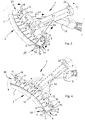
- Figures 1 to 4 show a doctor blade 1 provided with a deformable electrode 2, according to one of the constructive forms of the electrode described in the invention, in which the deformable electrode is supported and guided by a deformable body 3 of the doctor blade made up of upper 5 and lower 6 clamping elements 4, which, when tightened, grab the deformable electrode 2.
- the illustrated deformable electrode embodied by the second constructive form described, comprises a pad 7 for winding a metal wire 8, conducting the electric current, with a carbon fibre braid 9 interposed to cover the inner surface of the pad; the deformable electrode is completed by an inner pipe 10 for feeding the electrolytic solution to the said braid 9 for covering the pad so as to generate the electrolytic action between the metal wire 8 of the electrode, the carbon fibre braid 9 and the surface being treated, in contact with the pad 7 soaked in an electrolytic solution.
- the deformable body 3 of the doctor blade 1 is made by tightening the clamping elements 4 placed side by side and joined, in the direction F of the face of the doctor blade, i.e., the active face F of the electrode, by connections 11 between upper clamping elements 5, as well as between lower clamping elements 6, so as to achieve an increased pliability of the material forming the said clamping elements concentrated in such connections 11.
- tightening means 12 acting between said upper and lower clamping elements, which, when tightened, grab the dorsal end 13 of the deformable electrode 2 by means of teeth 14 on the outer surface of the pad 7 of such dorsal end.
- a metal cable 16 for the electrical connection to the electrode and a pipe 17 for supplying the electrolytic solution to the doctor blade come out from the handle 15 of the doctor blade 1.
- an electrical connection terminal 18 at each end, for supplying power to the metal wire 8, and, at least at one end, a connection 19 between the supplying pipe 17 and the inner pipe 10 for feeding the electrolytic solution into the pad, so as to make it easier to use for the operator.
- the doctor blade 1 is deformed to form a convex curvature, as shown in Figure 3 , or a concave one, as shown in Figure 4 , by acting on a slider, not shown, housed within the rail 21, placed between the handle 15 and the deformable body 3 of the doctor blade, and adjusted while moving towards the rail or moving away from it by means of a knob 22 acting on said slider; the slider is connected to push and / or pull rods 24 at the side ends 25 of the face F of the electrode on the doctor blade 1.
- the curvature is made possible by the deformability of the pad 7, of the inner pipe 10, of the metal wire 8, of the deformable body 3 of the doctor blade on the connections 11, which takes place in the same face position of the doctor blade itself, i.e., by the deformation of the active face F of the electrode.
- the elongations or compressions occur mainly on the outer surface of the pad 7 which is at a greater distance from the metal wire 8 located close to the direction of alignment of the tightening means 12 and of the connections 11 between the clamping elements 4, forming the deformable body 3 of the doctor blade 1.
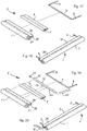
- Figures 5, 6 , 13, and 14 show the structure of the deformable electrode 20, embodied in the first simplified constructive form, herein provided with a wire 8 of the deformable electrode wrapped by the inner surface 27 of the pad 7; the metal wire 8 is in stable contact with said inner surface of the pad soaked in an electrolytic solution, so as to allow the electric current for actuating the electrolytic treatment to flow; the said inner surface 27 of the pad 7 is thus evenly supplied with the electric current and transfers the electrolytic action over the constant thickness S of the pad; thus the distance between a conductor, the metal wire, and the other conductor, the metal surface being treated, is constant for the activation of the pickling electrolytic action.
- the deformable electrode 20 is obtained by permanently joining the longitudinal ends 28 of the pad 7 in the dorsal end 13 of the deformable electrode.
- Figures 7, 8 , 15 and 16 show the structure of the deformable electrode 20, the first constructive form, herein provided with an inner pipe 10 for supplying the electrolytic solution, in which each similar or identical part is hereinafter referred to with the same numbering as in the preceding Figures.
- the metal wire 8 of the deformable electrode is wrapped by the inner surface 27 of the pad 7; the metal wire 8 is in stable contact with said inner surface of the pad soaked in an electrolytic solution, so as to allow the electric current for actuating the electrolytic treatment to flow; the said inner surface 27 of the pad 7 is thus evenly supplied with the electric current and transfers the electrolytic action over the constant thickness S of the pad; thus the distance between a conductor, the metal wire, and the other conductor, the metal surface being treated, is constant for the activation of the pickling electrolytic action.
- the deformable electrode 20 is obtained by permanently joining the longitudinal ends 28 of the pad 7 in the dorsal end 13 of the deformable electrode.
- the inner pipe 10 for supplying the electrolytic solution releases the solution over the length of the pad 7 from equally spaced holes 29, so as to keep the pad strip facing the metal surface being treated moistened; the inner pipe 10 terminates at one end 30 with a plug 31.
- Figures 9, 10 , 17, and 18 show the structure of the deformable electrode 2, in the second constructive form already described in the preceding Figures 1-4 , similar to the deformable electrode 20 described above but here lacking an inner pipe for supplying the electrolytic solution.
- This second constructive form of the deformable electrode is embodied by interposing a layer of carbon fibre braid 9 between the metal wire 8 and the inner surface 27 of the pad 7.
- Figures 11, 12 , 19 and 20 show the structure of the deformable electrode 2, in the second constructive form of the deformable electrode, herein provided with an inner pipe 10 for supplying the electrolytic solution, in which each similar or identical part is hereinafter referred to with the same numbering as in the preceding Figures.
- the metal wire 8 of the deformable electrode is wrapped by the inner surface 27 of the pad 7 on which the carbon fibre braid 9 is associated; the braid and the wire 8 are in stable, yet not tight contact, so as to allow the electric current for actuating the electrolytic treatment to flow; the distribution of the braid 9 allows the inner surface 27 of the pad 7 to be evenly supplied with the electric current so as to keep, at the thickness S of the pad, the distance between a conductor, the carbon fibre braid 9, and the other conductor, the metal surface being treated, constant for the activation of the pickling electrolytic action.
- the deformable electrode 2 is obtained by permanently joining the longitudinal ends 28 of the pad 7 in the dorsal end 13 of the deformable electrode.
- the inner pipe 10 for supplying the electrolytic solution releases the solution over the length of the pad 7 from equally spaced holes 29, so as to keep the pad strip facing the metal surface being treated moistened; the inner pipe terminates at one end 30 with a plug 31.
- Figures 21 to 24 illustrating the deformable electrode in the second constructive form, also depict the curvature which can be achieved also in the first electrode construction form; the curvatures show the deformations with curvature C of the deformable electrode 2 in which the compressed or elongated fibres mainly appear on the outer surface 32 of the pad and, correspondingly, on the longitudinal end 28 thereof.
- Figures 25 to 28 show the deformations with curvature C of the deformable electrode 2 in the second constructive form, but which also depict the curvature which can be achieved also in the first constructive form of deformable electrode, in which the compressed or elongated fibres mainly appear on the outer surface 32 of the pad or, possibly, on the longitudinal end 28 thereof; the inner pipe 10 in the concave conformation of Figures 27 and 28 , maintaining its own length unchanged, brings the end 30 closer to the termination of the pad by sliding therein.
- Figures 29 and 30 show the third constructive form of the deformable electrode 33, possibly provided with an inner pipe 10 for supplying the electrolytic solution to the pad 34 in the manner described for the constructive forms of the deformable electrode 2 and 20.
- the carbon fibre braid 9 is replaced by a distribution of intertwined carbon fibres 36 immersed in the thickness S of the pad, they being in contact with one another in the thickness of the pad and in contact in the inner surface of the pad 34 with the metal wire 8, which is placed as the deformable electrodes 2 and 20, while outside on the surface 32 for the contact between the pad 34 and the metal surface being treated, such fibres 36 emerge, showing their mutual intertwining visible in Figure.
- the deformable electrode of the third constructive form can thus similarly be provided without an inner pipe 10 for supplying the electrolytic solution to the pad 34.
- This deformable electrode 33 is assembled and used as described for the deformable electrodes 2 and 20 above.
- the curvatures achievable by this third constructive form are similar to those of the two preceding constructive forms.
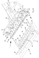
- Figures 31 and 32 show the fourth constructive form of the graphite deformable electrode 37.
- the metal wire 38 in this form of the electrode is inserted in dedicated holes of each graphite element 39 which are fixed onto the metal wire, equally spaced, as much as the clamping elements 4, by means of removable fasteners, not shown, fixing the graphite elements so that they are spaced apart and, therefore, couple with the said clamping elements 4 of a doctor blade 1.
- this constructive form of the graphite deformable electrode 37 there is also the supply of electric current in the same way as in the preceding Figures 1-4 , and the supply of electrolytic solution by means of an inner pipe 10 inserted between the front ends of the graphite elements 39 and the inner surface of the pad 41.
- the pad is fixed onto the graphite elements by means of removable elements 42 so as to make it replaceable, when needed.
- the electrolyte solution is supplied in the same way as in the preceding constructive form by means of the inner pipe 10, or in an uncomfortable way for the user by dipping the pad 41 in case the pipe 10 for supplying the electrolytic solution is not present.
- the doctor blade 1 is made similarly to the doctor blade of the preceding Figures and tightens each graphite element 39 of the graphite deformable electrode by means of the teeth 14 in each, both upper and lower, clamping element 4, i.e., this constructive form of deformable electrode 37 is interchangeable as the deformable electrodes 2, 20, and 33.
- this constructive form of deformable electrode 37 is interchangeable as the deformable electrodes 2, 20, and 33.
- the conformation of the pad 41 soaked in the electrolytic solution is fixed with removable elements 42 to each graphite element 35 of the graphite deformable electrode 34.
- the metal wire is advantageously made of nickel or tungsten
- the pads are made from a felt-like fabric made of a heat-resistant plastic material produced during the treatment and under the action of the chemicals present in the electrolytic solution used.
- Said plastic material is typically known as PEEK, the trade name of polyetheretherketone, or also as ZYLON, trade name, with the most suitable thickness of the pad in relation to the pickling effect to be achieved.
- the carbon elements can be made of solid graphite, i.e., a mechanically rigid amorphous carbon, as well as with carbon fibre braid or intertwined carbon fibres dispersed in the thickness of the pad itself.
- the deformable electrode for a doctor blade according to the invention is used as described for the adjustment of the curvature of the doctor blade 1 by acting on the position of the slider and of the ends 25 of the doctor blade with respect to the middle part of the doctor blade which is connected with the rail 21.
- the doctor blade may be moistened with the electrolytic solution fed into the deformable electrode through the pipe 10 and the holes 29 which it has in the section in contact with the pad 7, 34, or 41.
- the doctor blade may also be equipped with non-deformable electrodes, but this does not diminish its innovative characteristics, this being a transient effect in that, as visible and manageable, the arched conformation of the doctor blade is one potential use, but the doctor blade 1 may still be used with the rectilinear face F for treating flat surfaces, therefore the electrodes illustrated in the present description, being deformable, may be used as assembled in rigid doctor blade with a rectilinear or arch-shaped, whether concave or convex, conformation of the active face F of the electrode, maintaining the fixed shape due to the doctor blade itself.
- the presence of the pipe 10 for feeding the electrolytic solution is also optional.
- a fixed or deformable electrode 20, 33 may be provided without having the pipe 10 for feeding the electrolytic solution: to exploit the electrolytic pickling action, the operator will have to dip the pad of the doctor blade in use in a tray or bucket, not shown, to cause the pad 7, 34, or 41 itself to absorb the amount of electrolytic solution required each time to make the electrolytic action itself effective.
- the push or pull mechanism on the rods 24 changes the shape of the pad into convex, linear straight or concave, and vice versa.
- the mechanism itself may be made differently from what has been described, but still suitable for moving forward (push) or backward (pull) the ends of the rods 24 connected to the slider sliding in the rail 21.
- the flexibility and deformability of the pad 7, 34, or 41 allows the outer surface of the pad to achieve the required curvature C of the face F of the doctor blade.
- the advantage that can be obtained is achieving the versatility of the face of the doctor blade 1, i.e., of the active face of the electrode, in adapting to the curvature most suited to the surface during a pickling or cleaning treatment, whether it is convex, planar or concave.
Landscapes
- Chemical & Material Sciences (AREA)
- Engineering & Computer Science (AREA)
- Chemical Kinetics & Catalysis (AREA)
- Electrochemistry (AREA)
- Materials Engineering (AREA)
- Metallurgy (AREA)
- Organic Chemistry (AREA)
- Electroplating Methods And Accessories (AREA)
- Cleaning And De-Greasing Of Metallic Materials By Chemical Methods (AREA)
- Electrolytic Production Of Metals (AREA)
Claims (11)
- Elektrode für eine elektrolytisch wirkende Rakel (1) zum Beizen und Reinigen sowohl flacher als auch gekrümmter Metalloberflächen, die Folgendes umfasst: ein lineares Metallelement, das auf der Struktur der Rakel getragen und elektrisch an den elektrischen Schaltkreis angeschlossen ist, um die beizende elektrolytische Wirkung auszulösen; ein Polster aus einem filzartigen absorptionsfähigen Kunststoffmaterial, resistent gegenüber hohen Temperaturen und gegenüber den Chemikalien, die in der verwendeten elektrolytischen Lösung enthalten sind; dadurch gekennzeichnet, dass das lineare Metallelement aus einem Metalldraht (8, 38) besteht und ein Polster (7, 34, 41) mit konstanter Dicke (S) aus einem filzartigen absorptionsfähigen Kunststoffmaterial, das resistent gegenüber hohen Temperaturen und gegenüber den Chemikalien ist, die in der verwendeten elektrolytischen Lösung enthalten sind, dort herumgewickelt ist; wobei der Metalldraht nur an den Enden der Rakel (25) auf der aktiven Seite der verformbaren Elektrode (2, 20, 33, 35) mit der Struktur der Rakel verbunden ist.
- Elektrode für eine Rakel gemäß Anspruch 1, wobei Kohlenstoffelemente, die den Stromübertragungskontakt kontinuierlich auf das Polster und auf die elektrolytische Lösung verteilen, von der es durchdrungen ist, zwischen den Metalldraht (8, 38), verteilt über die Länge der aktiven Seite (F) der Elektrode, und das dort herumgewickelte Polster (7, 34, 41) platziert werden.
- Elektrode für eine Rakel gemäß Anspruch 2, wobei die Kohlenstoffelemente in einer Kohlenstofffaserlitze (9) bestehen, die zwischen den Metalldraht (8), und in Kontakt damit über die gesamte Länge der oben erwähnten aktiven Seite (F), und die Innenfläche des Polsters (7) platziert werden, das um den Metalldraht gewickelt ist.
- Elektrode für eine Rakel gemäß Anspruch 2, wobei die Kohlenstoffelemente in miteinander verflochtenen Kohlenstofffasern (36) bestehen, die in der Dicke des um den Metalldraht (8) gewickelten Polsters (34) verteilt sind; der Kontakt zwischen dem Metalldraht und den im Polster vorhandenen Kohlenstofffasern wird über die gesamte Länge der oben erwähnten aktiven Seite (F) hergestellt.
- Elektrode für eine Rakel gemäß Anspruch 2, wobei die Kohlenstoffelemente in Graphitelementen (39) bestehen, um welche das Polster (41) gewickelt und einzeln an jedem Element befestigt ist; der Metalldraht (38) wird eingeführt und an jedem Graphitelement befestigt, das die Elektrode bildet.
- Elektrode für eine Rakel gemäß einem beliebigen der obigen Ansprüche, wobei eine innere Leitung (10) zum Zuführen der elektrolytischen Lösung, um das Polster zu befeuchten, zwischen dem oben erwähnten Metalldraht und dem gewickelten Polster (7, 34, 41) angeordnet ist.
- Elektrode für eine Rakel gemäß einem der Ansprüche 1, 2 oder 3, wobei die Elektrode (2, 20, 33) ein dorsales Ende (13) hat, um das Klemmen der Rakel zu ermöglichen; wobei das dorsale Ende mit der Richtung der Seite der Rakel und mit der aktiven Seite (F) der Elektrode ausgerichtet ist.
- Elektrode für eine Rakel gemäß einem beliebigen der obigen Ansprüche, wobei der Metalldraht aus Nickel oder Wolfram besteht.
- Elektrode für eine Rakel gemäß einem beliebigen der obigen Ansprüche, wobei das Polster aus einem Kunststoffmaterial besteht, das aus PEEK, dem Handelsnamen von Polyetheretherketon, oder aus ZYLON - Handelsname - besteht.
- Rakel (1) für eine Elektrode zum Beizen und Reinigen sowohl flacher als auch gekrümmter Metalloberflächen, wobei die verformbare Elektrode (2, 20, 33, 37) gemäß einem der obigen Ansprüche bereitgestellt und durch das Festziehen von Klemmelementen (4) der Elektrode und eine elektrische Verbindung (16, 18) für jedes der Enden des Metalldrahts (8, 38), der die Elektrode bildet, an der Rakel befestigt ist.
- Rakel (1) für eine Elektrode gemäß Anspruch 10, wobei eine die elektrolytische Lösung zuführende Verbindung (17, 19) der inneren Leitung (10) zum Zuführen der elektrolytischen Lösung zum Polster bereitgestellt ist.
Applications Claiming Priority (2)
| Application Number | Priority Date | Filing Date | Title |
|---|---|---|---|
| IT102018000007874A IT201800007874A1 (it) | 2018-08-06 | 2018-08-06 | Elettrodo per azione elettrolitica di decapaggio e pulizia superficie metalliche |
| PCT/IT2019/050182 WO2020031220A1 (en) | 2018-08-06 | 2019-08-05 | An electrode for a doctor blade for pickling and cleaning metal surfaces |
Publications (2)
| Publication Number | Publication Date |
|---|---|
| EP3833802A1 EP3833802A1 (de) | 2021-06-16 |
| EP3833802B1 true EP3833802B1 (de) | 2022-07-13 |
Family
ID=63896586
Family Applications (1)
| Application Number | Title | Priority Date | Filing Date |
|---|---|---|---|
| EP19766369.3A Active EP3833802B1 (de) | 2018-08-06 | 2019-08-05 | Elektrode für eine rakel zum beizen und reinigen von metalloberflächen |
Country Status (4)
| Country | Link |
|---|---|
| US (1) | US11891717B2 (de) |
| EP (1) | EP3833802B1 (de) |
| IT (1) | IT201800007874A1 (de) |
| WO (1) | WO2020031220A1 (de) |
Families Citing this family (1)
| Publication number | Priority date | Publication date | Assignee | Title |
|---|---|---|---|---|
| CN117042521A (zh) * | 2023-08-01 | 2023-11-10 | 厦门天马微电子有限公司 | 显示面板及显示装置 |
Family Cites Families (10)
| Publication number | Priority date | Publication date | Assignee | Title |
|---|---|---|---|---|
| US4609450A (en) * | 1985-03-26 | 1986-09-02 | Agency Of Industrial Science And Technology | Combined electrolytic-abrasive polishing apparatus |
| JPH04157197A (ja) * | 1990-10-19 | 1992-05-29 | Kawasaki Steel Corp | 金属材表面の電解処理方法およびそれに用いる電極 |
| US5408926A (en) * | 1994-02-15 | 1995-04-25 | Alder; Robert A. | Pad transfer printing doctor blade and method |
| US5662041A (en) * | 1995-05-24 | 1997-09-02 | Trans Tech America, Inc. | Doctor blades for pad printing machines and machines including same |
| JP2005022361A (ja) * | 2003-07-02 | 2005-01-27 | Think Laboratory Co Ltd | ドクターブレードの刃先の加工方法 |
| JP4890210B2 (ja) * | 2006-11-24 | 2012-03-07 | 株式会社ドクター製作所 | ドクター装置のドクターブレード装着方法、ブレード差込溝のクリーニング方法、および、クリーニング用ブレード |
| JP2009289534A (ja) * | 2008-05-28 | 2009-12-10 | Idemitsu Kosan Co Ltd | 全固体リチウム電池用電極、全固体リチウム電池および装置 |
| US8597489B2 (en) * | 2010-07-08 | 2013-12-03 | General Electric Company | Method, apparatus and system for flexible electrochemical processing |
| ITMO20120020A1 (it) * | 2012-01-30 | 2013-07-31 | Edk S R L | Macchina per la elettromarcatura di grandi superficie metalliche e procedimento relativo |
| ITMO20130180A1 (it) * | 2013-06-21 | 2014-12-22 | Assembling S R L | Apparecchio per azione elettrolitica su filo metallico |
-
2018
- 2018-08-06 IT IT102018000007874A patent/IT201800007874A1/it unknown
-
2019
- 2019-08-05 EP EP19766369.3A patent/EP3833802B1/de active Active
- 2019-08-05 WO PCT/IT2019/050182 patent/WO2020031220A1/en not_active Ceased
- 2019-08-05 US US17/266,604 patent/US11891717B2/en active Active
Also Published As
| Publication number | Publication date |
|---|---|
| EP3833802A1 (de) | 2021-06-16 |
| WO2020031220A1 (en) | 2020-02-13 |
| US11891717B2 (en) | 2024-02-06 |
| IT201800007874A1 (it) | 2020-02-06 |
| US20210310148A1 (en) | 2021-10-07 |
Similar Documents
| Publication | Publication Date | Title |
|---|---|---|
| US8320988B2 (en) | Multi-electrode strung on a common connector | |
| US4159934A (en) | Selective plating brush applicator | |
| US4736752A (en) | Transcutaneous medical electrode | |
| US11891717B2 (en) | Electrode for a doctor blade for pickling and cleaning metal surfaces | |
| US11891716B2 (en) | Electrolytically acting doctor blade for pickling and cleaning curved metal surfaces | |
| JP5128166B2 (ja) | 電極パッド | |
| PT2345451T (pt) | Eléctrodos para aplicar um campo eléctrico in-vivo ao longo de um extenso período de tempo | |
| JP6675486B2 (ja) | 加熱要素を有する毛髪を処理するための装置用の化粧製品レフィル、およびそのようなレフィルを含む、毛髪を処理するための装置 | |
| WO2019104032A1 (en) | Hair brush | |
| JP2014507989A (ja) | 整髪器 | |
| AU2010207885A1 (en) | Conductive brush for cleaning metals | |
| EP1697563B1 (de) | Elektrodenvorrichtung mit integrierter elektrolytversorgung zur oberflächenbehandlung von metallen | |
| FR2576516A1 (fr) | Procede de traitement amincissant par ionophorese et dispositif pour l'application de traitements amincissants par ionophorese ou de traitements amaigrissants par galvanotherapie | |
| US1552591A (en) | Metal-plating device | |
| DK2868779T3 (en) | Device and method for cleaning and / or polishing workpieces. | |
| RU2004137117A (ru) | Гибкий нагревательный элемент с положительным температурным коэффициентом сопротивления и способ изготовления такого нагревательного элемента | |
| JPWO2015122014A1 (ja) | 電気温熱治療器用パッド | |
| CN202998516U (zh) | 具有电镀导电轨的柔性导电发热体 | |
| US2193086A (en) | Permanent waving | |
| SU652740A1 (ru) | Гибкий электронагреватель | |
| KR200425284Y1 (ko) | 카본섬유 면상발열체 | |
| CN107582374A (zh) | 专用于微电流刺激的耳夹电极 | |
| RU25133U1 (ru) | Гибкий электронагреватель | |
| KR20160040900A (ko) | 모발의 엉킴이 방지되는 헤어아이론 | |
| US722841A (en) | Electrical massage apparatus. |
Legal Events
| Date | Code | Title | Description |
|---|---|---|---|
| STAA | Information on the status of an ep patent application or granted ep patent |
Free format text: STATUS: UNKNOWN |
|
| STAA | Information on the status of an ep patent application or granted ep patent |
Free format text: STATUS: THE INTERNATIONAL PUBLICATION HAS BEEN MADE |
|
| PUAI | Public reference made under article 153(3) epc to a published international application that has entered the european phase |
Free format text: ORIGINAL CODE: 0009012 |
|
| STAA | Information on the status of an ep patent application or granted ep patent |
Free format text: STATUS: REQUEST FOR EXAMINATION WAS MADE |
|
| 17P | Request for examination filed |
Effective date: 20210304 |
|
| AK | Designated contracting states |
Kind code of ref document: A1 Designated state(s): AL AT BE BG CH CY CZ DE DK EE ES FI FR GB GR HR HU IE IS IT LI LT LU LV MC MK MT NL NO PL PT RO RS SE SI SK SM TR |
|
| DAV | Request for validation of the european patent (deleted) | ||
| DAX | Request for extension of the european patent (deleted) | ||
| REG | Reference to a national code |
Ref country code: DE Ref legal event code: R079 Ref document number: 602019017040 Country of ref document: DE Free format text: PREVIOUS MAIN CLASS: C25F0001020000 Ipc: C25F0001040000 |
|
| GRAP | Despatch of communication of intention to grant a patent |
Free format text: ORIGINAL CODE: EPIDOSNIGR1 |
|
| STAA | Information on the status of an ep patent application or granted ep patent |
Free format text: STATUS: GRANT OF PATENT IS INTENDED |
|
| RIC1 | Information provided on ipc code assigned before grant |
Ipc: C25F 7/00 20060101ALI20220228BHEP Ipc: C25F 1/04 20060101AFI20220228BHEP |
|
| INTG | Intention to grant announced |
Effective date: 20220323 |
|
| GRAS | Grant fee paid |
Free format text: ORIGINAL CODE: EPIDOSNIGR3 |
|
| GRAA | (expected) grant |
Free format text: ORIGINAL CODE: 0009210 |
|
| STAA | Information on the status of an ep patent application or granted ep patent |
Free format text: STATUS: THE PATENT HAS BEEN GRANTED |
|
| AK | Designated contracting states |
Kind code of ref document: B1 Designated state(s): AL AT BE BG CH CY CZ DE DK EE ES FI FR GB GR HR HU IE IS IT LI LT LU LV MC MK MT NL NO PL PT RO RS SE SI SK SM TR |
|
| REG | Reference to a national code |
Ref country code: CH Ref legal event code: EP |
|
| REG | Reference to a national code |
Ref country code: DE Ref legal event code: R096 Ref document number: 602019017040 Country of ref document: DE |
|
| REG | Reference to a national code |
Ref country code: AT Ref legal event code: REF Ref document number: 1504341 Country of ref document: AT Kind code of ref document: T Effective date: 20220815 |
|
| REG | Reference to a national code |
Ref country code: IE Ref legal event code: FG4D |
|
| REG | Reference to a national code |
Ref country code: LT Ref legal event code: MG9D |
|
| REG | Reference to a national code |
Ref country code: NL Ref legal event code: MP Effective date: 20220713 |
|
| PG25 | Lapsed in a contracting state [announced via postgrant information from national office to epo] |
Ref country code: SE Free format text: LAPSE BECAUSE OF FAILURE TO SUBMIT A TRANSLATION OF THE DESCRIPTION OR TO PAY THE FEE WITHIN THE PRESCRIBED TIME-LIMIT Effective date: 20220713 Ref country code: RS Free format text: LAPSE BECAUSE OF FAILURE TO SUBMIT A TRANSLATION OF THE DESCRIPTION OR TO PAY THE FEE WITHIN THE PRESCRIBED TIME-LIMIT Effective date: 20220713 Ref country code: PT Free format text: LAPSE BECAUSE OF FAILURE TO SUBMIT A TRANSLATION OF THE DESCRIPTION OR TO PAY THE FEE WITHIN THE PRESCRIBED TIME-LIMIT Effective date: 20221114 Ref country code: NO Free format text: LAPSE BECAUSE OF FAILURE TO SUBMIT A TRANSLATION OF THE DESCRIPTION OR TO PAY THE FEE WITHIN THE PRESCRIBED TIME-LIMIT Effective date: 20221013 Ref country code: NL Free format text: LAPSE BECAUSE OF FAILURE TO SUBMIT A TRANSLATION OF THE DESCRIPTION OR TO PAY THE FEE WITHIN THE PRESCRIBED TIME-LIMIT Effective date: 20220713 Ref country code: LV Free format text: LAPSE BECAUSE OF FAILURE TO SUBMIT A TRANSLATION OF THE DESCRIPTION OR TO PAY THE FEE WITHIN THE PRESCRIBED TIME-LIMIT Effective date: 20220713 Ref country code: LT Free format text: LAPSE BECAUSE OF FAILURE TO SUBMIT A TRANSLATION OF THE DESCRIPTION OR TO PAY THE FEE WITHIN THE PRESCRIBED TIME-LIMIT Effective date: 20220713 Ref country code: FI Free format text: LAPSE BECAUSE OF FAILURE TO SUBMIT A TRANSLATION OF THE DESCRIPTION OR TO PAY THE FEE WITHIN THE PRESCRIBED TIME-LIMIT Effective date: 20220713 Ref country code: ES Free format text: LAPSE BECAUSE OF FAILURE TO SUBMIT A TRANSLATION OF THE DESCRIPTION OR TO PAY THE FEE WITHIN THE PRESCRIBED TIME-LIMIT Effective date: 20220713 |
|
| REG | Reference to a national code |
Ref country code: AT Ref legal event code: MK05 Ref document number: 1504341 Country of ref document: AT Kind code of ref document: T Effective date: 20220713 |
|
| PG25 | Lapsed in a contracting state [announced via postgrant information from national office to epo] |
Ref country code: PL Free format text: LAPSE BECAUSE OF FAILURE TO SUBMIT A TRANSLATION OF THE DESCRIPTION OR TO PAY THE FEE WITHIN THE PRESCRIBED TIME-LIMIT Effective date: 20220713 Ref country code: IS Free format text: LAPSE BECAUSE OF FAILURE TO SUBMIT A TRANSLATION OF THE DESCRIPTION OR TO PAY THE FEE WITHIN THE PRESCRIBED TIME-LIMIT Effective date: 20221113 Ref country code: HR Free format text: LAPSE BECAUSE OF FAILURE TO SUBMIT A TRANSLATION OF THE DESCRIPTION OR TO PAY THE FEE WITHIN THE PRESCRIBED TIME-LIMIT Effective date: 20220713 Ref country code: GR Free format text: LAPSE BECAUSE OF FAILURE TO SUBMIT A TRANSLATION OF THE DESCRIPTION OR TO PAY THE FEE WITHIN THE PRESCRIBED TIME-LIMIT Effective date: 20221014 |
|
| REG | Reference to a national code |
Ref country code: CH Ref legal event code: PL |
|
| REG | Reference to a national code |
Ref country code: DE Ref legal event code: R097 Ref document number: 602019017040 Country of ref document: DE |
|
| PG25 | Lapsed in a contracting state [announced via postgrant information from national office to epo] |
Ref country code: SM Free format text: LAPSE BECAUSE OF FAILURE TO SUBMIT A TRANSLATION OF THE DESCRIPTION OR TO PAY THE FEE WITHIN THE PRESCRIBED TIME-LIMIT Effective date: 20220713 Ref country code: RO Free format text: LAPSE BECAUSE OF FAILURE TO SUBMIT A TRANSLATION OF THE DESCRIPTION OR TO PAY THE FEE WITHIN THE PRESCRIBED TIME-LIMIT Effective date: 20220713 Ref country code: MC Free format text: LAPSE BECAUSE OF FAILURE TO SUBMIT A TRANSLATION OF THE DESCRIPTION OR TO PAY THE FEE WITHIN THE PRESCRIBED TIME-LIMIT Effective date: 20220713 Ref country code: LU Free format text: LAPSE BECAUSE OF NON-PAYMENT OF DUE FEES Effective date: 20220805 Ref country code: LI Free format text: LAPSE BECAUSE OF NON-PAYMENT OF DUE FEES Effective date: 20220831 Ref country code: DK Free format text: LAPSE BECAUSE OF FAILURE TO SUBMIT A TRANSLATION OF THE DESCRIPTION OR TO PAY THE FEE WITHIN THE PRESCRIBED TIME-LIMIT Effective date: 20220713 Ref country code: CZ Free format text: LAPSE BECAUSE OF FAILURE TO SUBMIT A TRANSLATION OF THE DESCRIPTION OR TO PAY THE FEE WITHIN THE PRESCRIBED TIME-LIMIT Effective date: 20220713 Ref country code: CH Free format text: LAPSE BECAUSE OF NON-PAYMENT OF DUE FEES Effective date: 20220831 Ref country code: AT Free format text: LAPSE BECAUSE OF FAILURE TO SUBMIT A TRANSLATION OF THE DESCRIPTION OR TO PAY THE FEE WITHIN THE PRESCRIBED TIME-LIMIT Effective date: 20220713 |
|
| REG | Reference to a national code |
Ref country code: BE Ref legal event code: MM Effective date: 20220831 |
|
| PLBE | No opposition filed within time limit |
Free format text: ORIGINAL CODE: 0009261 |
|
| STAA | Information on the status of an ep patent application or granted ep patent |
Free format text: STATUS: NO OPPOSITION FILED WITHIN TIME LIMIT |
|
| PG25 | Lapsed in a contracting state [announced via postgrant information from national office to epo] |
Ref country code: SK Free format text: LAPSE BECAUSE OF FAILURE TO SUBMIT A TRANSLATION OF THE DESCRIPTION OR TO PAY THE FEE WITHIN THE PRESCRIBED TIME-LIMIT Effective date: 20220713 Ref country code: EE Free format text: LAPSE BECAUSE OF FAILURE TO SUBMIT A TRANSLATION OF THE DESCRIPTION OR TO PAY THE FEE WITHIN THE PRESCRIBED TIME-LIMIT Effective date: 20220713 |
|
| 26N | No opposition filed |
Effective date: 20230414 |
|
| PG25 | Lapsed in a contracting state [announced via postgrant information from national office to epo] |
Ref country code: AL Free format text: LAPSE BECAUSE OF FAILURE TO SUBMIT A TRANSLATION OF THE DESCRIPTION OR TO PAY THE FEE WITHIN THE PRESCRIBED TIME-LIMIT Effective date: 20220713 |
|
| PG25 | Lapsed in a contracting state [announced via postgrant information from national office to epo] |
Ref country code: IE Free format text: LAPSE BECAUSE OF NON-PAYMENT OF DUE FEES Effective date: 20220805 |
|
| PG25 | Lapsed in a contracting state [announced via postgrant information from national office to epo] |
Ref country code: SI Free format text: LAPSE BECAUSE OF FAILURE TO SUBMIT A TRANSLATION OF THE DESCRIPTION OR TO PAY THE FEE WITHIN THE PRESCRIBED TIME-LIMIT Effective date: 20220713 |
|
| PG25 | Lapsed in a contracting state [announced via postgrant information from national office to epo] |
Ref country code: BE Free format text: LAPSE BECAUSE OF NON-PAYMENT OF DUE FEES Effective date: 20220831 |
|
| PG25 | Lapsed in a contracting state [announced via postgrant information from national office to epo] |
Ref country code: CY Free format text: LAPSE BECAUSE OF FAILURE TO SUBMIT A TRANSLATION OF THE DESCRIPTION OR TO PAY THE FEE WITHIN THE PRESCRIBED TIME-LIMIT Effective date: 20220713 |
|
| PG25 | Lapsed in a contracting state [announced via postgrant information from national office to epo] |
Ref country code: MK Free format text: LAPSE BECAUSE OF FAILURE TO SUBMIT A TRANSLATION OF THE DESCRIPTION OR TO PAY THE FEE WITHIN THE PRESCRIBED TIME-LIMIT Effective date: 20220713 Ref country code: HU Free format text: LAPSE BECAUSE OF FAILURE TO SUBMIT A TRANSLATION OF THE DESCRIPTION OR TO PAY THE FEE WITHIN THE PRESCRIBED TIME-LIMIT; INVALID AB INITIO Effective date: 20190805 |
|
| PG25 | Lapsed in a contracting state [announced via postgrant information from national office to epo] |
Ref country code: TR Free format text: LAPSE BECAUSE OF FAILURE TO SUBMIT A TRANSLATION OF THE DESCRIPTION OR TO PAY THE FEE WITHIN THE PRESCRIBED TIME-LIMIT Effective date: 20220713 |
|
| PG25 | Lapsed in a contracting state [announced via postgrant information from national office to epo] |
Ref country code: BG Free format text: LAPSE BECAUSE OF FAILURE TO SUBMIT A TRANSLATION OF THE DESCRIPTION OR TO PAY THE FEE WITHIN THE PRESCRIBED TIME-LIMIT Effective date: 20220713 |
|
| PG25 | Lapsed in a contracting state [announced via postgrant information from national office to epo] |
Ref country code: MT Free format text: LAPSE BECAUSE OF FAILURE TO SUBMIT A TRANSLATION OF THE DESCRIPTION OR TO PAY THE FEE WITHIN THE PRESCRIBED TIME-LIMIT Effective date: 20220713 |
|
| PGFP | Annual fee paid to national office [announced via postgrant information from national office to epo] |
Ref country code: DE Payment date: 20250828 Year of fee payment: 7 |
|
| PGFP | Annual fee paid to national office [announced via postgrant information from national office to epo] |
Ref country code: IT Payment date: 20250827 Year of fee payment: 7 |
|
| PGFP | Annual fee paid to national office [announced via postgrant information from national office to epo] |
Ref country code: GB Payment date: 20250827 Year of fee payment: 7 |
|
| PGFP | Annual fee paid to national office [announced via postgrant information from national office to epo] |
Ref country code: FR Payment date: 20250826 Year of fee payment: 7 |