EP3833503B1 - Werkzeugmaschine zur bearbeitung von sägescheiben und verfahren zu ihrer verwendung - Google Patents
Werkzeugmaschine zur bearbeitung von sägescheiben und verfahren zu ihrer verwendung Download PDFInfo
- Publication number
- EP3833503B1 EP3833503B1 EP19769238.7A EP19769238A EP3833503B1 EP 3833503 B1 EP3833503 B1 EP 3833503B1 EP 19769238 A EP19769238 A EP 19769238A EP 3833503 B1 EP3833503 B1 EP 3833503B1
- Authority
- EP
- European Patent Office
- Prior art keywords
- disk
- sensor
- processing
- disks
- tool
- Prior art date
- Legal status (The legal status is an assumption and is not a legal conclusion. Google has not performed a legal analysis and makes no representation as to the accuracy of the status listed.)
- Active
Links
Images


Classifications
-
- B—PERFORMING OPERATIONS; TRANSPORTING
- B23—MACHINE TOOLS; METAL-WORKING NOT OTHERWISE PROVIDED FOR
- B23D—PLANING; SLOTTING; SHEARING; BROACHING; SAWING; FILING; SCRAPING; LIKE OPERATIONS FOR WORKING METAL BY REMOVING MATERIAL, NOT OTHERWISE PROVIDED FOR
- B23D63/00—Dressing the tools of sawing machines or sawing devices for use in cutting any kind of material, e.g. in the manufacture of sawing tools
- B23D63/18—Straightening damaged saw blades; Reconditioning the side surface of saw blades, e.g. by grinding
-
- B—PERFORMING OPERATIONS; TRANSPORTING
- B23—MACHINE TOOLS; METAL-WORKING NOT OTHERWISE PROVIDED FOR
- B23D—PLANING; SLOTTING; SHEARING; BROACHING; SAWING; FILING; SCRAPING; LIKE OPERATIONS FOR WORKING METAL BY REMOVING MATERIAL, NOT OTHERWISE PROVIDED FOR
- B23D65/00—Making tools for sawing machines or sawing devices for use in cutting any kind of material
-
- B—PERFORMING OPERATIONS; TRANSPORTING
- B23—MACHINE TOOLS; METAL-WORKING NOT OTHERWISE PROVIDED FOR
- B23D—PLANING; SLOTTING; SHEARING; BROACHING; SAWING; FILING; SCRAPING; LIKE OPERATIONS FOR WORKING METAL BY REMOVING MATERIAL, NOT OTHERWISE PROVIDED FOR
- B23D63/00—Dressing the tools of sawing machines or sawing devices for use in cutting any kind of material, e.g. in the manufacture of sawing tools
- B23D63/008—Dressing the tools of sawing machines or sawing devices for use in cutting any kind of material, e.g. in the manufacture of sawing tools using computer control means
Definitions
- This invention relates to the machine tool field, which today is very widespread in all mechanical workshops, often being designed and built to carry out very specific tasks.
- the present invention relates to a machine device tool for processing saw disks and to methods of using it.
- Document US 3 964 348 A discloses a machine device tool for processing saw disks, comprising at least one processor, a spindle unit comprising in turn at least one shank provided with a flange on which a semi-finished tool saw disk to be planarized is mounted, said device comprising at least one sensor assembly comprising at least one sensor mounted on a carriage to slide at least from the periphery of said disk to the centre of said disk, said sensor detecting the differences in planarity in at least each part of a disk face and communicating said data to said processor said device further comprising at least one hammer assembly comprising at least one beating head, at least one element for giving to said beating head the thrust for striking areas of discrepancy in planarity detected by said at least one sensor, said processing being determined by said processor.
- the two faces of the disk must necessarily comply with the tolerances of planarity with reference to a plane identified by the flange that clamps on the spindle to ensure proper operation of the disks themselves.
- a machine device tool for processing saw disks defined by the features of claim 1 is provided.
- a further purpose of the present invention is to describe a device that allows to carry out all the said operations in a safe and industrially repeatable way.
- One more purpose of this invention is to describe a device that allows such processing to be carried out quickly and economically.
- said machine comprising at least one spindle unit, with at least one shank 16 fitted with a flange, connected to said spindle 2 on which a saw disk to be planarized is mounted, said device being characterized by the fact that it comprises a sensor assembly 4 comprising at least one carriage 11 for handling at least one sensor 10 for measuring planarity differences on at least one face of the saw disk on each part of that face, the planarity differences being detectable substantially indistinctly on either face.
- the innovative machine tool described herein is dedicated to the production of saw-disks usually used for cutting wood, especially those suitable for cutting panel wood.
- a planarizing saw-disk is mounted on a spindle of said machine by means, for example, of a shank with a flange, connected to said spindle, the disk is mounted on the spindle and then rotated by the spindle; a capacitive planarity sensor is made to slide by means of a carriage, from the periphery of the disk to its innermost part (near the spindle coupling).
- Such sensor is used to detect the differences in each part of the two faces of the disk, for example by detecting the distance of the surface of the disk from a reference plane determined by the plane of the clamping flange (by virtue of the rotation of the disk and of the translatory movement of the sensor in the radial direction, a total coverage and scanning of the faces to be analyzed is achieved).
- the areas that will present differences lower than a certain predetermined threshold can be considered within the tolerance ranges, while the differences exceeding that predetermined threshold will be those to be hit by the hammer, in order to bring these differences within tolerance.
- a sensor detects and measures the differences in planarity present on the surfaces of the two faces of the disk, a hammer hits the area affected by the differences identified by the sensor, the sensor returns to check and, if the planarity is within the limits, the disk is unloaded (otherwise the operation can be repeated until the result is obtained).
- a hammer assembly with a beating head including at least one preload spring to give a beating head the correct thrust to strike the areas of detected discrepancy.
- the force with which to operate the hammer on these areas will be determined by a computer based on a database.
- a database can be built from which it will be possible to obtain for each disk examined by the sensor a processing program of the hammer that, advantageously, can be used as a reference in similar future cases.
- said database will be structured, which will essentially allow the machine to work autonomously in an even more precise way by virtue of said database and "self-learning" capacity.
- Said method for using said machine comprises as a minimum at least the phase of:
- the hammer in a preferential form of construction consists of a hammer that is pushed against the target by a spring compressed by a pneumatic cylinder controlled by the computer, (namely the point on the face of the disk where the planar deformity was detected) discharging its kinetic energy against the protruding deformity from the ideal reference plane, this plane being the one identified by the flange of the spindle on which the disk is locked.
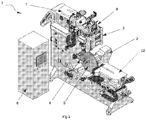
- a workpiece/disk 5 is already mounted on the machine tool 1.
- Said workpiece 5 or disk is mounted on a spindle unit 2 by means of a quick coupling by means of a shank 16 which will be described in more detail in the following figures.
- a tensioning unit 12 in this case for example provided with rollers, will be used to compact the steel of the disk giving it a structural rib that will make it more stable through a compression applied between the two faces of the disk to be machined.
- disk 5 begins to rotate by means of spindle 2, the disk having an axis of rotation coinciding with that of said spindle.
- Sensor assembly 4 can perform a translatory movement in the direction of the spindle rotation axis and allows a capacitive sensor (visible in figure 2 ) mounted, for example, at an end of sensor assembly 4, to move from the periphery of disk 5, namely the external circumference of the disk, to the part closest to the attachment shank 16, namely to the centre of the disk being machined 5.
- the composition of degrees of freedom namely the rotation of disk 5 and the movement of the sensor with translatory movement along the surface of disk 5, will make it possible to analyze the entire surface of the disk itself: the capacitive sensor will detect point by point (with a resolution that can be defined a priori by the computer and regulator 6) data regarding the areas out of tolerance of planarity, in particular regarding the surface of the area out of tolerance and the thickness or degree of relief with respect to the plane (if such roughnesses exist).
- the spatial coordinates of these areas are identified, for example, by measuring at least two coordinates, such as for example, an angular coordinate of the spindle axis and a straight coordinate relative to the displacement of the sensor according to a straight coordinate relative to the displacement of the carriage on which the sensor 10 is mounted, these coordinates form a part of the data.
- the data sent in the first place are: those collected by the sensor in relation to the position of the deformation and its degree of relevance will be transmitted continuously to a computer and regulator 6 able to record not only the deformations before processing but also the changes that occurred after the "hammering" carried out in order to recover the tolerance: so there will be data sent to the computer 6 also whenever it is performed a "correction" operation on the disk, to control the result.
- the computer 6 will then command the hammer assembly 3, (which will be further described in a later figure), by sending data relating to the thrust parameters that must be applied on the impact mass (namely to the head of the hammer, by a spring) in order to hit the zone or area out of tolerance detected with the force indicated by the computer 6.
- hammer assembly 3 will position itself with its active part, namely the hammering head, close to that area, exerting one or more percussions depending on the degree of tolerance to be corrected.
- Hammer assembly 3 will be able to work the entire surface of the disk by virtue of the rotation of disk 5 on the axis of the spindle and by virtue of the displacement of hammer assembly 3 in the vertical direction made by a vertical carriage 7 and a transverse displacement made by a transverse carriage 8.
- the computer 6, therefore, will provide to maintain both an archive of the processing carried out and will also use this archive for a subsequent self-regulation of the processing parameters based on the results previously obtained.
- the computer and regulator 6 can also perform functions of self-adaptive control, this in a completely innovative and advantageous way, also excluding in this phase of processing totally the presence of staff who could do the same job based only on their experience and with certainly greater times (and risks). This operation becomes therefore repeatable and industrially reproducible in a simple and effective way.
- the moving part is driven, for example, by an electric motor.
- the sensor 10 can examine the whole surface of disk 5 thanks also to the rotation of said disk. Said capacitive sensor 10, will detect the discrepancies present on both faces of the disk, in fact the defects of planarity being detectable substantially indistinctly from one or the other face usually as said to a hump on one face corresponds a depression on the other face, at least for the most common defects.
- At least two sensors can be present, one for measurement on each face of the disk, or the disk can be rotated for measurement on the other face, or the sensor can be rotated, this for greater accuracy.
- Fig. 3 shows the part of spindle assembly 2 in which the head of the spindle 9 on which the disk will be mounted is highlighted for the processing phase on the innovative machine tool.
- the spindle will be equipped with a quick coupling in which to insert a shank for tightening the disk to be machined.
- the shank (not visible here) can be fixed to the spindle, for example, by means of a ball coupling controlled by a pneumatic piston 25, able to hold the shank in its seat 10 in the spindle head 9.
- the head of the spindle 9 will rotate the disk 5 both for a first phase of planarity analysis, and for a second phase of actual processing, which will be carried out by means of the hammer that will correct the areas out of tolerance and/or excessively deformed.
- the figure shows the structural elements that support the spindle head and the motor for its drive. Obvious technical details are not specified and are merely construction details.
- Fig. 4 shows the detail of the hammer assembly 3 which is connected to the transversal carriage 8 and which includes as substantial elements at least a hammer 13 and a spring 15 with a preload piston 14 (not visible here).
- the preload piston depending on the amount of force to be used to correct a certain degree of defect detected by sensor 10 on the surface of disk 5, will load the spring 15 which will then transfer the elastic energy at the time of the blow, to the beating head.
- the force with which to preload the spring will be determined to time by time autonomously by the computer and regulator 6 that, based upon learning on the previously processed cases, will determine independently how to best dose this force in order to obtain the desired effect.
- FIG. 4a A detail of hammer assembly 3 is visible in figure 4a where in particular it is represented the hammer head 13 that comprises at least one beating bolt 300 and at least one additional anvil bolt 301 to act as a stop for the beating bolt. Among them is obviously placed the disk to be worked on. There are also pads 302, for example made of rubber, mounted on pneumatic cylinders 303 which avoid the resonance of the disk after the blow. To eliminate friction between the beating head 13 and its housing 130, compressed air is injected (by means of a solenoid valve or a suitable medium) in this housing to form an air cushion, thus avoiding the sliding of the head into the housing and the consequent wear and tear.
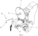
- Figs. 5a and 5b show a variant of a preferred form of design of a system 80 for loading and unloading the disk on/from the machine, in order to facilitate the positioning of large disks.
- This system can be optionally present on the machine tool object of the invention. With the increase of the diameter and consequent thickness of the blades, it becomes physically difficult and demanding the unloading but above all the loading of the blades.
- System 80 includes at least a support 21, a handgrip 19, a handwheel 18, to said structural support 21 are fixed solidly a plurality of blade supports 17 to support the disk to be mounted and there are also fixed solidly said handgrip and said handwheel, this to perform positioning and/or unloading in a semiautomatic way even for the heaviest disks.
- the handgrip 19 is grasped and the system 80 is dragged until the end of the stroke (towards the operator), a handwheel 18 is rotated to adjust the blade supports 17 in relation to the diameter of the blade/disk 5 that will be mounted (a numeric indicator is further included in which it is expressed in mm corresponding to the diameter of the blade to be loaded).
- a numeric indicator is further included in which it is expressed in mm corresponding to the diameter of the blade to be loaded.
- the 80 system further includes a part of the frame 30 connected to the support 21, by means of a hinge that allows the rotation of the support 21 with respect to the frame 30 of a small angle, this rotation is made by exerting a force on the handgrip 19, favoring the insertion of the shank 16 in the spindle and then the fixing of the blade on the spindle, the blade is substantially pushed on the spindle, the supports accordingly are axially and radially distance from the teeth of the blade allowing it to rotate and release from the supports 17.
- the present invention allows to solve all the described problems of prior art allowing to obtain all the described advantages, noting that variants in materials used for the machine, materials in which the disks are made, size and weight of the same, variants in the type of sensors for measurements, in the mode of assembly parts, provided that they achieve the purposes of this invention, means of automation, type of carriages, etc.. are all considered variants of the embodiment of the invention as defined by the claims.
Landscapes
- Engineering & Computer Science (AREA)
- Mechanical Engineering (AREA)
- General Engineering & Computer Science (AREA)
- Machine Tool Sensing Apparatuses (AREA)
- Manufacturing Of Magnetic Record Carriers (AREA)
- Finish Polishing, Edge Sharpening, And Grinding By Specific Grinding Devices (AREA)
Claims (8)
- Werkzeugmaschine (1) für die Bearbeitung von Sägescheiben (5), mit wenigstens einem Prozessor (6), einer Spindeleinheit (2), die ihrerseits wenigstens einen Schaft (16) umfasst, der mit einer Flansch Fläche versehen ist, auf der eine halbfertige, zu planierende Sägescheibe (5) montiert ist, wobei die Vorrichtung zumindest eine Sensoranordnung (4) umfasst, die wenigstens einen Sensor (10) aufweist, der auf einem Schlitten (11) montiert ist, um wenigstens vom Umfang der Scheibe zur Mitte der Scheibe zu gleiten, der Sensor ermittelt die Unterschiede in der Ebenheit in mindestens jedem Teil einer Scheibenfläche und übermittelt die Daten an den Prozessor (6). Die Vorrichtung umfasst außerdem mindestens eine Hammerbaugruppe (3), die mindestens einen Schlagkopf (13) und mindestens eine Vorspannfeder (15) umfasst, um dem Schlagkopf den Schub zu gewähren, damit er auf die von dem mindestens einen Sensor (10) ermittelten Bereiche mit Abweichungen in der Ebenheit schlägt, wobei der Schub oder die Verarbeitung von dem Prozessor bestimmt wird.
- Werkzeugmaschine (1) zur Bearbeitung von Sägescheiben (5) nach Anspruch 1, wobei der Schlitten (11) eine translatorische Bewegung in radialer Richtung der Scheibe (5) und der sich um ihre Mittelachse drehenden Scheibe gewähren kann in Bezug auf den Sensor (10), sodass die vollständige Abtastung mindestens einer Seite der Scheibe (5) möglich ist.
- Werkzeugmaschine (1) für die Bearbeitung von Sägescheiben (5) nach einem der vorangehenden Ansprüche, bei der mindestens zwei Sensoren (10) vorhanden sind, einer für die Messung auf jeder Seite der Scheibe, oder die Scheibe (5) für die Messung auf der ersten und zweiten Seite gedreht werden kann, oder der Sensor für eine höhere Erfassungsgenauigkeit auf die andere Seite der Scheibe bewegt werden kann.
- Werkzeugmaschine (1) für die Bearbeitung von Sägescheiben (5) nach einem der vorhergehenden Ansprüche, bei der der Hammer (13) wenigstens einen Schlagbolzen (300) und wenigstens einen zusätzlichen Amboss Bolzen (301) aufweist, der als Anschlag für den Schlagbolzen dient, und bei der die zu bearbeitende Scheibe (5) zwischen auf Pneumatik-Zylindern (303) montierten Auflagen (302) angeordnet ist.
- Werkzeugmaschine (1) für die Bearbeitung von Sägescheiben (5) nach dem vorhergehenden Anspruch, bei der der Sensor (10) ein kapazitiver Sensor ist.
- Werkzeugmaschine (1) für die Bearbeitung von Sägescheiben (5) nach einem der vorhergehenden Ansprüche, mit einem Be-/Entladesystem (80), das zumindest einen Träger (21), einen Handgriff (19) und ein Handrad (18) umfasst, wobei an der Träger (21) Blattstützen (17) zum Abstützen der zu montierenden Scheibe fest angebracht sind und auch der Handgriff und das Handrad dort fest angebracht sind, wobei das System in der Lage ist, die Scheibe (5) auf der Spindeleinheit (2) zu positionieren, um die Positionierung und/oder die halbautomatische Entladung selbst der schwersten Scheiben (5) durchzuführen.
- Verfahren zur Bearbeitung von Sägescheiben (5) mit der Werkzeugmaschine (1) nach einem der vorhergehenden Ansprüche, bei dem: der Prozessor (6)- Die von dem mindestens einen Sensor (10) erfassten Daten speichert;
die Schubkraft für die durchgeführten Arbeiten kontrolliert;- Daten mittels des mindestens einen Sensors (10) sammelt, nachdem die Bearbeitungsvorgänge durchgeführt worden sind;- Korrekturparameter für künftige Bearbeitungen mit im Wesentlichen identischen Daten speichert und verarbeitet, um die Bearbeitung zu beschleunigen;
wobei der Prozessor so ausgelegt ist, dass er selbstlernend arbeitet. - Verfahren zur Bearbeitung von Sägescheiben (5) unter Anwendung der Werkzeugmaschine (1) nach den vorhergehenden Ansprüchen 1-6, wobei:- mindestens ein Sensor (10) Daten über die Ebenheit der Oberfläche der Scheibe (5) sammelt;- Daten verarbeitet werden;wobei im Falle einer Abweichung die folgenden Schritte durchgeführt werden:- Verarbeitung der auszuführenden Korrektur durch den Prozessor (6);- Durchführung der Korrektur durch einen Befehl an den Schlagkopf (13) und- Überprüfung des mithilfe des Sensors (10) erzielten Ergebnisses;wobei, wenn sich die Korrektur innerhalb eines Toleranzbereichs befindet, der Prozess beendet und die Scheibe entladen wird, wobei, wenn die Korrektur sich außerhalb des Datentoleranzbereichs befindet, die folgenden Schritte durchgeführt werden:- Erkennung von Unregelmäßigkeiten in der Ebenheit der Scheibe durch den Sensor (10);- Wiederholung der Korrekturarbeiten, bis ein Ergebnis innerhalb des Bereichs erzielt wird;Danach ist der Vorgang beendet und die Scheibe wird entladen.
Applications Claiming Priority (2)
| Application Number | Priority Date | Filing Date | Title |
|---|---|---|---|
| IT102018000008070A IT201800008070A1 (it) | 2018-08-10 | 2018-08-10 | Macchina utensile per la lavorazione di dischi da sega |
| PCT/IB2019/056631 WO2020031051A1 (en) | 2018-08-10 | 2019-08-04 | Machine tool for processing saw disks |
Publications (2)
| Publication Number | Publication Date |
|---|---|
| EP3833503A1 EP3833503A1 (de) | 2021-06-16 |
| EP3833503B1 true EP3833503B1 (de) | 2022-09-28 |
Family
ID=64049608
Family Applications (1)
| Application Number | Title | Priority Date | Filing Date |
|---|---|---|---|
| EP19769238.7A Active EP3833503B1 (de) | 2018-08-10 | 2019-08-04 | Werkzeugmaschine zur bearbeitung von sägescheiben und verfahren zu ihrer verwendung |
Country Status (4)
| Country | Link |
|---|---|
| US (1) | US11478866B2 (de) |
| EP (1) | EP3833503B1 (de) |
| IT (1) | IT201800008070A1 (de) |
| WO (1) | WO2020031051A1 (de) |
Families Citing this family (1)
| Publication number | Priority date | Publication date | Assignee | Title |
|---|---|---|---|---|
| CN115647479A (zh) * | 2022-12-26 | 2023-01-31 | 江苏陆氏金刚石工具有限公司 | 一种金刚石锯片加工用自动化打磨开刃装置 |
Family Cites Families (8)
| Publication number | Priority date | Publication date | Assignee | Title |
|---|---|---|---|---|
| US3964348A (en) * | 1975-03-04 | 1976-06-22 | Remington Arms Company, Inc. | Method and machine for straightening and tensioning saw blades |
| DE2638161C3 (de) * | 1976-08-25 | 1979-03-22 | 4600 Dortmund | Vorrichtung zum Richten von Kreissägen-Blechrohlingen, insbes. von Warmkreissagen |
| US5522283A (en) * | 1995-01-09 | 1996-06-04 | International Paper Company | Circular saw leveling and tensioning machine |
| FI100777B (fi) * | 1995-06-02 | 1998-02-27 | Veisto Rakenne Rautio Oy | Menetelmä ja laitteisto pyörösahanterän oikomiseksi |
| US6305258B1 (en) * | 1998-02-18 | 2001-10-23 | International Business Machines Corporation | Punch actuator monitoring system and method |
| ES2237433T3 (es) * | 2000-06-09 | 2005-08-01 | Automatismi Brazzale S.R.L | Maquina para la correccion de errores de planeidad de herramientas de forma discoidal. |
| ITVI20050320A1 (it) * | 2005-12-02 | 2007-06-03 | Automatismi Brazzale Srl | Macchina multifunzionale per la correzione degli errori di planarita' e dello stato di tensionamento di lame discoidali, nonche' metodo e programma di controllo di tale macchina |
| US20160158819A1 (en) * | 2014-12-03 | 2016-06-09 | Paul E. Johnson | Compact Pneumatic Auto Body Hammer with Fine Control of Impact Force |
-
2018
- 2018-08-10 IT IT102018000008070A patent/IT201800008070A1/it unknown
-
2019
- 2019-08-04 WO PCT/IB2019/056631 patent/WO2020031051A1/en not_active Ceased
- 2019-08-04 EP EP19769238.7A patent/EP3833503B1/de active Active
- 2019-08-04 US US17/266,130 patent/US11478866B2/en active Active
Also Published As
| Publication number | Publication date |
|---|---|
| WO2020031051A1 (en) | 2020-02-13 |
| EP3833503A1 (de) | 2021-06-16 |
| IT201800008070A1 (it) | 2020-02-10 |
| US11478866B2 (en) | 2022-10-25 |
| US20210252619A1 (en) | 2021-08-19 |
Similar Documents
| Publication | Publication Date | Title |
|---|---|---|
| EP2455191B1 (de) | Schleifmaschine und messvorrichtung | |
| JP5260139B2 (ja) | 砥石接触感知方法およびその装置、ならびにホーニング加工方法およびホーニング盤 | |
| US5115403A (en) | Workpiece workability detection method and a method for cutting a workpiece by means of a cutting machine utilizing that method | |
| US9630284B2 (en) | Configurable welding table and force indicating clamp | |
| US20190217441A1 (en) | Robotized hammering method and robotized system for implementing the method | |
| US20020189312A1 (en) | Apparatus for deep rolling of recesses and radii of crankshaft journal bearings | |
| EP3338949B1 (de) | Festwalzwerkzeug und -verfahren | |
| EP3833503B1 (de) | Werkzeugmaschine zur bearbeitung von sägescheiben und verfahren zu ihrer verwendung | |
| JP4733947B2 (ja) | 予切削した歯を有する被加工物を歯車仕上げ加工機上で位置合わせする方法及び装置 | |
| EP3112044B1 (de) | Walzmaschine zum ausbilden von gewinden auf zylindrischen körpern und verfahren zum synchronisieren von formwalzen einer walzmaschine | |
| EP1721703B1 (de) | Verfahren zur Steuerung eines Prägepolierverfahrens | |
| EP2617517A1 (de) | Festwalzwerkzeug und Verfahren | |
| EP3338939B1 (de) | Festwalzwerkzeug und -verfahren | |
| CN113319687A (zh) | 控制机床中的接触力 | |
| JP2008183655A (ja) | ホーニング加工方法、ホーニング盤の砥石切込み装置およびホーニング盤 | |
| WO2026088068A1 (en) | Machine tool for planarizing saw discs | |
| EP4061579B1 (de) | Schleifkopf mit klappenrädern | |
| EP1960144A2 (de) | Mehrfunktionswerkzeugmaschine zur korrektur von unebenheiten und verringerung von spannung in scheibenförmigen messern sowie verfahren und programm zur steuerung solch einer maschine | |
| CN121552017B (zh) | 隔板套加工方法 | |
| EP4556163A1 (de) | Entwurf eines robotischen tiefwalzwerkzeugs zur mechanischen oberflächenbehandlung einer komplexen schaufelfussgeometrie | |
| US20250303519A1 (en) | Robotic deep rolling tool design for surface texturing to control friction and coating bonding | |
| EP1294517B1 (de) | Maschine zur korrektur von unebenheiten in scheibenförmigen werkzeugen | |
| EP4177005A2 (de) | Verbesserte bearbeitungseinheit | |
| WO2025234348A1 (ja) | 研削方法、研削装置および金属製品の製造方法 | |
| Dacal-Nieto et al. | A Cyber-Physical Methodology to Automate Robotized Finishing Processes |
Legal Events
| Date | Code | Title | Description |
|---|---|---|---|
| STAA | Information on the status of an ep patent application or granted ep patent |
Free format text: STATUS: UNKNOWN |
|
| STAA | Information on the status of an ep patent application or granted ep patent |
Free format text: STATUS: THE INTERNATIONAL PUBLICATION HAS BEEN MADE |
|
| PUAI | Public reference made under article 153(3) epc to a published international application that has entered the european phase |
Free format text: ORIGINAL CODE: 0009012 |
|
| STAA | Information on the status of an ep patent application or granted ep patent |
Free format text: STATUS: REQUEST FOR EXAMINATION WAS MADE |
|
| 17P | Request for examination filed |
Effective date: 20210304 |
|
| AK | Designated contracting states |
Kind code of ref document: A1 Designated state(s): AL AT BE BG CH CY CZ DE DK EE ES FI FR GB GR HR HU IE IS IT LI LT LU LV MC MK MT NL NO PL PT RO RS SE SI SK SM TR |
|
| DAV | Request for validation of the european patent (deleted) | ||
| DAX | Request for extension of the european patent (deleted) | ||
| GRAP | Despatch of communication of intention to grant a patent |
Free format text: ORIGINAL CODE: EPIDOSNIGR1 |
|
| STAA | Information on the status of an ep patent application or granted ep patent |
Free format text: STATUS: GRANT OF PATENT IS INTENDED |
|
| INTG | Intention to grant announced |
Effective date: 20220323 |
|
| GRAS | Grant fee paid |
Free format text: ORIGINAL CODE: EPIDOSNIGR3 |
|
| GRAA | (expected) grant |
Free format text: ORIGINAL CODE: 0009210 |
|
| STAA | Information on the status of an ep patent application or granted ep patent |
Free format text: STATUS: THE PATENT HAS BEEN GRANTED |
|
| AK | Designated contracting states |
Kind code of ref document: B1 Designated state(s): AL AT BE BG CH CY CZ DE DK EE ES FI FR GB GR HR HU IE IS IT LI LT LU LV MC MK MT NL NO PL PT RO RS SE SI SK SM TR |
|
| REG | Reference to a national code |
Ref country code: GB Ref legal event code: FG4D |
|
| REG | Reference to a national code |
Ref country code: CH Ref legal event code: EP |
|
| REG | Reference to a national code |
Ref country code: AT Ref legal event code: REF Ref document number: 1520934 Country of ref document: AT Kind code of ref document: T Effective date: 20221015 |
|
| REG | Reference to a national code |
Ref country code: DE Ref legal event code: R096 Ref document number: 602019020094 Country of ref document: DE |
|
| REG | Reference to a national code |
Ref country code: IE Ref legal event code: FG4D |
|
| REG | Reference to a national code |
Ref country code: NL Ref legal event code: FP |
|
| REG | Reference to a national code |
Ref country code: LT Ref legal event code: MG9D |
|
| PG25 | Lapsed in a contracting state [announced via postgrant information from national office to epo] |
Ref country code: SE Free format text: LAPSE BECAUSE OF FAILURE TO SUBMIT A TRANSLATION OF THE DESCRIPTION OR TO PAY THE FEE WITHIN THE PRESCRIBED TIME-LIMIT Effective date: 20220928 Ref country code: RS Free format text: LAPSE BECAUSE OF FAILURE TO SUBMIT A TRANSLATION OF THE DESCRIPTION OR TO PAY THE FEE WITHIN THE PRESCRIBED TIME-LIMIT Effective date: 20220928 Ref country code: NO Free format text: LAPSE BECAUSE OF FAILURE TO SUBMIT A TRANSLATION OF THE DESCRIPTION OR TO PAY THE FEE WITHIN THE PRESCRIBED TIME-LIMIT Effective date: 20221228 Ref country code: LV Free format text: LAPSE BECAUSE OF FAILURE TO SUBMIT A TRANSLATION OF THE DESCRIPTION OR TO PAY THE FEE WITHIN THE PRESCRIBED TIME-LIMIT Effective date: 20220928 Ref country code: LT Free format text: LAPSE BECAUSE OF FAILURE TO SUBMIT A TRANSLATION OF THE DESCRIPTION OR TO PAY THE FEE WITHIN THE PRESCRIBED TIME-LIMIT Effective date: 20220928 Ref country code: FI Free format text: LAPSE BECAUSE OF FAILURE TO SUBMIT A TRANSLATION OF THE DESCRIPTION OR TO PAY THE FEE WITHIN THE PRESCRIBED TIME-LIMIT Effective date: 20220928 |
|
| REG | Reference to a national code |
Ref country code: AT Ref legal event code: MK05 Ref document number: 1520934 Country of ref document: AT Kind code of ref document: T Effective date: 20220928 |
|
| PG25 | Lapsed in a contracting state [announced via postgrant information from national office to epo] |
Ref country code: HR Free format text: LAPSE BECAUSE OF FAILURE TO SUBMIT A TRANSLATION OF THE DESCRIPTION OR TO PAY THE FEE WITHIN THE PRESCRIBED TIME-LIMIT Effective date: 20220928 Ref country code: GR Free format text: LAPSE BECAUSE OF FAILURE TO SUBMIT A TRANSLATION OF THE DESCRIPTION OR TO PAY THE FEE WITHIN THE PRESCRIBED TIME-LIMIT Effective date: 20221229 |
|
| PG25 | Lapsed in a contracting state [announced via postgrant information from national office to epo] |
Ref country code: SM Free format text: LAPSE BECAUSE OF FAILURE TO SUBMIT A TRANSLATION OF THE DESCRIPTION OR TO PAY THE FEE WITHIN THE PRESCRIBED TIME-LIMIT Effective date: 20220928 Ref country code: RO Free format text: LAPSE BECAUSE OF FAILURE TO SUBMIT A TRANSLATION OF THE DESCRIPTION OR TO PAY THE FEE WITHIN THE PRESCRIBED TIME-LIMIT Effective date: 20220928 Ref country code: PT Free format text: LAPSE BECAUSE OF FAILURE TO SUBMIT A TRANSLATION OF THE DESCRIPTION OR TO PAY THE FEE WITHIN THE PRESCRIBED TIME-LIMIT Effective date: 20230130 Ref country code: ES Free format text: LAPSE BECAUSE OF FAILURE TO SUBMIT A TRANSLATION OF THE DESCRIPTION OR TO PAY THE FEE WITHIN THE PRESCRIBED TIME-LIMIT Effective date: 20220928 Ref country code: CZ Free format text: LAPSE BECAUSE OF FAILURE TO SUBMIT A TRANSLATION OF THE DESCRIPTION OR TO PAY THE FEE WITHIN THE PRESCRIBED TIME-LIMIT Effective date: 20220928 Ref country code: AT Free format text: LAPSE BECAUSE OF FAILURE TO SUBMIT A TRANSLATION OF THE DESCRIPTION OR TO PAY THE FEE WITHIN THE PRESCRIBED TIME-LIMIT Effective date: 20220928 |
|
| PG25 | Lapsed in a contracting state [announced via postgrant information from national office to epo] |
Ref country code: SK Free format text: LAPSE BECAUSE OF FAILURE TO SUBMIT A TRANSLATION OF THE DESCRIPTION OR TO PAY THE FEE WITHIN THE PRESCRIBED TIME-LIMIT Effective date: 20220928 Ref country code: PL Free format text: LAPSE BECAUSE OF FAILURE TO SUBMIT A TRANSLATION OF THE DESCRIPTION OR TO PAY THE FEE WITHIN THE PRESCRIBED TIME-LIMIT Effective date: 20220928 Ref country code: IS Free format text: LAPSE BECAUSE OF FAILURE TO SUBMIT A TRANSLATION OF THE DESCRIPTION OR TO PAY THE FEE WITHIN THE PRESCRIBED TIME-LIMIT Effective date: 20230128 Ref country code: EE Free format text: LAPSE BECAUSE OF FAILURE TO SUBMIT A TRANSLATION OF THE DESCRIPTION OR TO PAY THE FEE WITHIN THE PRESCRIBED TIME-LIMIT Effective date: 20220928 |
|
| REG | Reference to a national code |
Ref country code: DE Ref legal event code: R097 Ref document number: 602019020094 Country of ref document: DE |
|
| PG25 | Lapsed in a contracting state [announced via postgrant information from national office to epo] |
Ref country code: AL Free format text: LAPSE BECAUSE OF FAILURE TO SUBMIT A TRANSLATION OF THE DESCRIPTION OR TO PAY THE FEE WITHIN THE PRESCRIBED TIME-LIMIT Effective date: 20220928 |
|
| PG25 | Lapsed in a contracting state [announced via postgrant information from national office to epo] |
Ref country code: DK Free format text: LAPSE BECAUSE OF FAILURE TO SUBMIT A TRANSLATION OF THE DESCRIPTION OR TO PAY THE FEE WITHIN THE PRESCRIBED TIME-LIMIT Effective date: 20220928 |
|
| PLBE | No opposition filed within time limit |
Free format text: ORIGINAL CODE: 0009261 |
|
| STAA | Information on the status of an ep patent application or granted ep patent |
Free format text: STATUS: NO OPPOSITION FILED WITHIN TIME LIMIT |
|
| 26N | No opposition filed |
Effective date: 20230629 |
|
| PG25 | Lapsed in a contracting state [announced via postgrant information from national office to epo] |
Ref country code: SI Free format text: LAPSE BECAUSE OF FAILURE TO SUBMIT A TRANSLATION OF THE DESCRIPTION OR TO PAY THE FEE WITHIN THE PRESCRIBED TIME-LIMIT Effective date: 20220928 |
|
| PG25 | Lapsed in a contracting state [announced via postgrant information from national office to epo] |
Ref country code: MC Free format text: LAPSE BECAUSE OF FAILURE TO SUBMIT A TRANSLATION OF THE DESCRIPTION OR TO PAY THE FEE WITHIN THE PRESCRIBED TIME-LIMIT Effective date: 20220928 |
|
| REG | Reference to a national code |
Ref country code: CH Ref legal event code: PL |
|
| PG25 | Lapsed in a contracting state [announced via postgrant information from national office to epo] |
Ref country code: MC Free format text: LAPSE BECAUSE OF FAILURE TO SUBMIT A TRANSLATION OF THE DESCRIPTION OR TO PAY THE FEE WITHIN THE PRESCRIBED TIME-LIMIT Effective date: 20220928 |
|
| PG25 | Lapsed in a contracting state [announced via postgrant information from national office to epo] |
Ref country code: LU Free format text: LAPSE BECAUSE OF NON-PAYMENT OF DUE FEES Effective date: 20230804 |
|
| PG25 | Lapsed in a contracting state [announced via postgrant information from national office to epo] |
Ref country code: LU Free format text: LAPSE BECAUSE OF NON-PAYMENT OF DUE FEES Effective date: 20230804 Ref country code: CH Free format text: LAPSE BECAUSE OF NON-PAYMENT OF DUE FEES Effective date: 20230831 |
|
| REG | Reference to a national code |
Ref country code: IE Ref legal event code: MM4A |
|
| PG25 | Lapsed in a contracting state [announced via postgrant information from national office to epo] |
Ref country code: IT Free format text: LAPSE BECAUSE OF FAILURE TO SUBMIT A TRANSLATION OF THE DESCRIPTION OR TO PAY THE FEE WITHIN THE PRESCRIBED TIME-LIMIT Effective date: 20220928 |
|
| PG25 | Lapsed in a contracting state [announced via postgrant information from national office to epo] |
Ref country code: IE Free format text: LAPSE BECAUSE OF NON-PAYMENT OF DUE FEES Effective date: 20230804 |
|
| PG25 | Lapsed in a contracting state [announced via postgrant information from national office to epo] |
Ref country code: IE Free format text: LAPSE BECAUSE OF NON-PAYMENT OF DUE FEES Effective date: 20230804 |
|
| PG25 | Lapsed in a contracting state [announced via postgrant information from national office to epo] |
Ref country code: BG Free format text: LAPSE BECAUSE OF FAILURE TO SUBMIT A TRANSLATION OF THE DESCRIPTION OR TO PAY THE FEE WITHIN THE PRESCRIBED TIME-LIMIT Effective date: 20220928 |
|
| PG25 | Lapsed in a contracting state [announced via postgrant information from national office to epo] |
Ref country code: BG Free format text: LAPSE BECAUSE OF FAILURE TO SUBMIT A TRANSLATION OF THE DESCRIPTION OR TO PAY THE FEE WITHIN THE PRESCRIBED TIME-LIMIT Effective date: 20220928 |
|
| PG25 | Lapsed in a contracting state [announced via postgrant information from national office to epo] |
Ref country code: CY Free format text: LAPSE BECAUSE OF FAILURE TO SUBMIT A TRANSLATION OF THE DESCRIPTION OR TO PAY THE FEE WITHIN THE PRESCRIBED TIME-LIMIT; INVALID AB INITIO Effective date: 20190804 |
|
| PG25 | Lapsed in a contracting state [announced via postgrant information from national office to epo] |
Ref country code: HU Free format text: LAPSE BECAUSE OF FAILURE TO SUBMIT A TRANSLATION OF THE DESCRIPTION OR TO PAY THE FEE WITHIN THE PRESCRIBED TIME-LIMIT; INVALID AB INITIO Effective date: 20190804 |
|
| PGFP | Annual fee paid to national office [announced via postgrant information from national office to epo] |
Ref country code: NL Payment date: 20250804 Year of fee payment: 7 |
|
| PGFP | Annual fee paid to national office [announced via postgrant information from national office to epo] |
Ref country code: DE Payment date: 20250806 Year of fee payment: 7 |
|
| PGFP | Annual fee paid to national office [announced via postgrant information from national office to epo] |
Ref country code: BE Payment date: 20250804 Year of fee payment: 7 Ref country code: GB Payment date: 20250711 Year of fee payment: 7 |
|
| PGFP | Annual fee paid to national office [announced via postgrant information from national office to epo] |
Ref country code: FR Payment date: 20250801 Year of fee payment: 7 |
|
| PG25 | Lapsed in a contracting state [announced via postgrant information from national office to epo] |
Ref country code: TR Free format text: LAPSE BECAUSE OF FAILURE TO SUBMIT A TRANSLATION OF THE DESCRIPTION OR TO PAY THE FEE WITHIN THE PRESCRIBED TIME-LIMIT Effective date: 20220928 |