EP3832173A1 - Balg, dessen verwendung und verfahren zu seiner herstellung - Google Patents
Balg, dessen verwendung und verfahren zu seiner herstellung Download PDFInfo
- Publication number
- EP3832173A1 EP3832173A1 EP20210270.3A EP20210270A EP3832173A1 EP 3832173 A1 EP3832173 A1 EP 3832173A1 EP 20210270 A EP20210270 A EP 20210270A EP 3832173 A1 EP3832173 A1 EP 3832173A1
- Authority
- EP
- European Patent Office
- Prior art keywords
- layer
- bellows
- layers
- bellows according
- foamed
- Prior art date
- Legal status (The legal status is an assumption and is not a legal conclusion. Google has not performed a legal analysis and makes no representation as to the accuracy of the status listed.)
- Granted
Links
Images


Classifications
-
- F—MECHANICAL ENGINEERING; LIGHTING; HEATING; WEAPONS; BLASTING
- F16—ENGINEERING ELEMENTS AND UNITS; GENERAL MEASURES FOR PRODUCING AND MAINTAINING EFFECTIVE FUNCTIONING OF MACHINES OR INSTALLATIONS; THERMAL INSULATION IN GENERAL
- F16J—PISTONS; CYLINDERS; SEALINGS
- F16J3/00—Diaphragms; Bellows; Bellows pistons
- F16J3/04—Bellows
- F16J3/041—Non-metallic bellows
-
- B—PERFORMING OPERATIONS; TRANSPORTING
- B29—WORKING OF PLASTICS; WORKING OF SUBSTANCES IN A PLASTIC STATE IN GENERAL
- B29C—SHAPING OR JOINING OF PLASTICS; SHAPING OF MATERIAL IN A PLASTIC STATE, NOT OTHERWISE PROVIDED FOR; AFTER-TREATMENT OF THE SHAPED PRODUCTS, e.g. REPAIRING
- B29C48/00—Extrusion moulding, i.e. expressing the moulding material through a die or nozzle which imparts the desired form; Apparatus therefor
- B29C48/001—Combinations of extrusion moulding with other shaping operations
- B29C48/0017—Combinations of extrusion moulding with other shaping operations combined with blow-moulding or thermoforming
-
- B—PERFORMING OPERATIONS; TRANSPORTING
- B29—WORKING OF PLASTICS; WORKING OF SUBSTANCES IN A PLASTIC STATE IN GENERAL
- B29C—SHAPING OR JOINING OF PLASTICS; SHAPING OF MATERIAL IN A PLASTIC STATE, NOT OTHERWISE PROVIDED FOR; AFTER-TREATMENT OF THE SHAPED PRODUCTS, e.g. REPAIRING
- B29C48/00—Extrusion moulding, i.e. expressing the moulding material through a die or nozzle which imparts the desired form; Apparatus therefor
- B29C48/03—Extrusion moulding, i.e. expressing the moulding material through a die or nozzle which imparts the desired form; Apparatus therefor characterised by the shape of the extruded material at extrusion
- B29C48/09—Articles with cross-sections having partially or fully enclosed cavities, e.g. pipes or channels
-
- B—PERFORMING OPERATIONS; TRANSPORTING
- B29—WORKING OF PLASTICS; WORKING OF SUBSTANCES IN A PLASTIC STATE IN GENERAL
- B29C—SHAPING OR JOINING OF PLASTICS; SHAPING OF MATERIAL IN A PLASTIC STATE, NOT OTHERWISE PROVIDED FOR; AFTER-TREATMENT OF THE SHAPED PRODUCTS, e.g. REPAIRING
- B29C48/00—Extrusion moulding, i.e. expressing the moulding material through a die or nozzle which imparts the desired form; Apparatus therefor
- B29C48/03—Extrusion moulding, i.e. expressing the moulding material through a die or nozzle which imparts the desired form; Apparatus therefor characterised by the shape of the extruded material at extrusion
- B29C48/13—Articles with a cross-section varying in the longitudinal direction, e.g. corrugated pipes
-
- B—PERFORMING OPERATIONS; TRANSPORTING
- B29—WORKING OF PLASTICS; WORKING OF SUBSTANCES IN A PLASTIC STATE IN GENERAL
- B29C—SHAPING OR JOINING OF PLASTICS; SHAPING OF MATERIAL IN A PLASTIC STATE, NOT OTHERWISE PROVIDED FOR; AFTER-TREATMENT OF THE SHAPED PRODUCTS, e.g. REPAIRING
- B29C48/00—Extrusion moulding, i.e. expressing the moulding material through a die or nozzle which imparts the desired form; Apparatus therefor
- B29C48/16—Articles comprising two or more components, e.g. co-extruded layers
- B29C48/18—Articles comprising two or more components, e.g. co-extruded layers the components being layers
- B29C48/21—Articles comprising two or more components, e.g. co-extruded layers the components being layers the layers being joined at their surfaces
-
- B—PERFORMING OPERATIONS; TRANSPORTING
- B29—WORKING OF PLASTICS; WORKING OF SUBSTANCES IN A PLASTIC STATE IN GENERAL
- B29C—SHAPING OR JOINING OF PLASTICS; SHAPING OF MATERIAL IN A PLASTIC STATE, NOT OTHERWISE PROVIDED FOR; AFTER-TREATMENT OF THE SHAPED PRODUCTS, e.g. REPAIRING
- B29C49/00—Blow-moulding, i.e. blowing a preform or parison to a desired shape within a mould; Apparatus therefor
- B29C49/02—Combined blow-moulding and manufacture of the preform or the parison
- B29C49/04—Extrusion blow-moulding
- B29C49/0411—Means for defining the wall or layer thickness
- B29C49/04114—Means for defining the wall or layer thickness for keeping constant thickness
-
- B—PERFORMING OPERATIONS; TRANSPORTING
- B32—LAYERED PRODUCTS
- B32B—LAYERED PRODUCTS, i.e. PRODUCTS BUILT-UP OF STRATA OF FLAT OR NON-FLAT, e.g. CELLULAR OR HONEYCOMB, FORM
- B32B33/00—Layered products characterised by particular properties or particular surface features, e.g. particular surface coatings; Layered products designed for particular purposes not covered by another single class
-
- B—PERFORMING OPERATIONS; TRANSPORTING
- B32—LAYERED PRODUCTS
- B32B—LAYERED PRODUCTS, i.e. PRODUCTS BUILT-UP OF STRATA OF FLAT OR NON-FLAT, e.g. CELLULAR OR HONEYCOMB, FORM
- B32B5/00—Layered products characterised by the non- homogeneity or physical structure, i.e. comprising a fibrous, filamentary, particulate or foam layer; Layered products characterised by having a layer differing constitutionally or physically in different parts
- B32B5/18—Layered products characterised by the non- homogeneity or physical structure, i.e. comprising a fibrous, filamentary, particulate or foam layer; Layered products characterised by having a layer differing constitutionally or physically in different parts characterised by features of a layer of foamed material
-
- B—PERFORMING OPERATIONS; TRANSPORTING
- B32—LAYERED PRODUCTS
- B32B—LAYERED PRODUCTS, i.e. PRODUCTS BUILT-UP OF STRATA OF FLAT OR NON-FLAT, e.g. CELLULAR OR HONEYCOMB, FORM
- B32B7/00—Layered products characterised by the relation between layers; Layered products characterised by the relative orientation of features between layers, or by the relative values of a measurable parameter between layers, i.e. products comprising layers having different physical, chemical or physicochemical properties; Layered products characterised by the interconnection of layers
- B32B7/02—Physical, chemical or physicochemical properties
-
- F—MECHANICAL ENGINEERING; LIGHTING; HEATING; WEAPONS; BLASTING
- F16—ENGINEERING ELEMENTS AND UNITS; GENERAL MEASURES FOR PRODUCING AND MAINTAINING EFFECTIVE FUNCTIONING OF MACHINES OR INSTALLATIONS; THERMAL INSULATION IN GENERAL
- F16J—PISTONS; CYLINDERS; SEALINGS
- F16J15/00—Sealings
- F16J15/50—Sealings between relatively-movable members, by means of a sealing without relatively-moving surfaces, e.g. fluid-tight sealings for transmitting motion through a wall
- F16J15/52—Sealings between relatively-movable members, by means of a sealing without relatively-moving surfaces, e.g. fluid-tight sealings for transmitting motion through a wall by means of sealing bellows or diaphragms
-
- F—MECHANICAL ENGINEERING; LIGHTING; HEATING; WEAPONS; BLASTING
- F16—ENGINEERING ELEMENTS AND UNITS; GENERAL MEASURES FOR PRODUCING AND MAINTAINING EFFECTIVE FUNCTIONING OF MACHINES OR INSTALLATIONS; THERMAL INSULATION IN GENERAL
- F16J—PISTONS; CYLINDERS; SEALINGS
- F16J3/00—Diaphragms; Bellows; Bellows pistons
- F16J3/04—Bellows
- F16J3/041—Non-metallic bellows
- F16J3/043—Non-metallic bellows with particular means for limiting wear
-
- B—PERFORMING OPERATIONS; TRANSPORTING
- B32—LAYERED PRODUCTS
- B32B—LAYERED PRODUCTS, i.e. PRODUCTS BUILT-UP OF STRATA OF FLAT OR NON-FLAT, e.g. CELLULAR OR HONEYCOMB, FORM
- B32B1/00—Layered products having a non-planar shape
- B32B1/08—Tubular products
-
- B—PERFORMING OPERATIONS; TRANSPORTING
- B32—LAYERED PRODUCTS
- B32B—LAYERED PRODUCTS, i.e. PRODUCTS BUILT-UP OF STRATA OF FLAT OR NON-FLAT, e.g. CELLULAR OR HONEYCOMB, FORM
- B32B2250/00—Layers arrangement
- B32B2250/40—Symmetrical or sandwich layers, e.g. ABA, ABCBA, ABCCBA
-
- B—PERFORMING OPERATIONS; TRANSPORTING
- B32—LAYERED PRODUCTS
- B32B—LAYERED PRODUCTS, i.e. PRODUCTS BUILT-UP OF STRATA OF FLAT OR NON-FLAT, e.g. CELLULAR OR HONEYCOMB, FORM
- B32B2266/00—Composition of foam
- B32B2266/02—Organic
- B32B2266/0214—Materials belonging to B32B27/00
- B32B2266/0292—Thermoplastic elastomer
-
- B—PERFORMING OPERATIONS; TRANSPORTING
- B32—LAYERED PRODUCTS
- B32B—LAYERED PRODUCTS, i.e. PRODUCTS BUILT-UP OF STRATA OF FLAT OR NON-FLAT, e.g. CELLULAR OR HONEYCOMB, FORM
- B32B2274/00—Thermoplastic elastomer material
-
- B—PERFORMING OPERATIONS; TRANSPORTING
- B32—LAYERED PRODUCTS
- B32B—LAYERED PRODUCTS, i.e. PRODUCTS BUILT-UP OF STRATA OF FLAT OR NON-FLAT, e.g. CELLULAR OR HONEYCOMB, FORM
- B32B25/00—Layered products comprising a layer of natural or synthetic rubber
- B32B25/04—Layered products comprising a layer of natural or synthetic rubber comprising rubber as the main or only constituent of a layer, which is next to another layer of the same or of a different material
- B32B25/045—Layered products comprising a layer of natural or synthetic rubber comprising rubber as the main or only constituent of a layer, which is next to another layer of the same or of a different material of foam
-
- B—PERFORMING OPERATIONS; TRANSPORTING
- B32—LAYERED PRODUCTS
- B32B—LAYERED PRODUCTS, i.e. PRODUCTS BUILT-UP OF STRATA OF FLAT OR NON-FLAT, e.g. CELLULAR OR HONEYCOMB, FORM
- B32B2597/00—Tubular articles, e.g. hoses, pipes
-
- B—PERFORMING OPERATIONS; TRANSPORTING
- B32—LAYERED PRODUCTS
- B32B—LAYERED PRODUCTS, i.e. PRODUCTS BUILT-UP OF STRATA OF FLAT OR NON-FLAT, e.g. CELLULAR OR HONEYCOMB, FORM
- B32B2605/00—Vehicles
-
- B—PERFORMING OPERATIONS; TRANSPORTING
- B32—LAYERED PRODUCTS
- B32B—LAYERED PRODUCTS, i.e. PRODUCTS BUILT-UP OF STRATA OF FLAT OR NON-FLAT, e.g. CELLULAR OR HONEYCOMB, FORM
- B32B3/00—Layered products comprising a layer with external or internal discontinuities or unevennesses, or a layer of non-planar shape; Layered products comprising a layer having particular features of form
- B32B3/26—Layered products comprising a layer with external or internal discontinuities or unevennesses, or a layer of non-planar shape; Layered products comprising a layer having particular features of form characterised by a particular shape of the outline of the cross-section of a continuous layer; characterised by a layer with cavities or internal voids ; characterised by an apertured layer
- B32B3/28—Layered products comprising a layer with external or internal discontinuities or unevennesses, or a layer of non-planar shape; Layered products comprising a layer having particular features of form characterised by a particular shape of the outline of the cross-section of a continuous layer; characterised by a layer with cavities or internal voids ; characterised by an apertured layer characterised by a layer comprising a deformed thin sheet, i.e. the layer having its entire thickness deformed out of the plane, e.g. corrugated, crumpled
Definitions
- the invention relates to a bellows, its use and a method for its production.
- Bellows are well known and often consist of thermoplastic elastomers.
- the previously known bellows have a single-layer structure and are produced from a blown tube by extrusion blow molding, among other things. Due to the single-layer structure, a bellows can often only be insufficiently adapted to the particular circumstances of the application. Partial areas of a single-layer bellows also inevitably consist of the one material used, for which another material might be more suitable, for example with regard to the properties of use, the lowest possible weight or more economical manufacturability. In particular, when the material used is expensive, the bellows made from it is also expensive.
- the invention is based on the object of further developing a bellows and a method for its production in each case in such a way that the bellows has good usage properties over a long period of use, can be better adapted to the particular circumstances of the application and that the bellows can be produced easily and inexpensively.
- a use of such a bellows should also be mentioned.
- a bellows is provided with an at least two-layer structure, comprising at least one first layer and at least one second layer.
- the advantage here is that the different layers of the bellows are each functionally individualized. For example, each material is only used for the layer for which it is also suitable / necessary in order to ensure good performance properties of the bellows over a long period of use.
- the use of a material that is oversized in terms of price, weight, durability, for example, is no longer necessary due to the multi-layer structure of the bellows.
- Each layer can be designed in such a way as is necessary for good performance properties over a long period of use, with special consideration given to economic producibility.
- one of the layers is made from a foam, for example, this saves material compared to a layer made from an unfoamed material, so that the bellows can be manufactured more cost-effectively and more easily overall.
- the layers are inextricably linked to one another due to the manufacturing process and the material used.
- Compatible materials are preferred, for example TPC-EE, -ET and -EE with PBT or TPV with PP matrix.
- TPC-EE with PBT has the advantage that this combination is particularly heat-resistant, solid and dynamic.
- TPV with a PP matrix has the advantage that this combination is particularly cost-effective and is sufficient for certain applications.
- the handling of the bellows according to the invention is still simple in comparison to a bellows with only a single-layer structure.
- the assembly and disassembly of the bellows, as well as the performance properties of the bellows during its intended use do not differ, if only advantageously, from good single-layer bellows.
- the layers can consist of materials that differ from one another and / or have densities that differ from one another. With such a configuration there are many possible variations, so that such a bellows with an at least two-layer structure can be adapted particularly well to the respective requirements of the application.
- the first three material combinations are preferably used for bellows on the drive shaft to seal constant velocity joints.
- the other combinations are more likely to be used for bellows for the steering or other chassis parts.
- PP with TPV tends to be used for lower temperature requirements, combinations with PA are preferred for high temperature requirements.
- the materials mentioned are therefore well compatible with one another because they are chemically similar.
- the strength and other properties of the recyclate are then similar to those of the materials of the individual layers.
- Bellows whose layers are made of the same material can be recycled particularly easily. This enables single-type recycling. This is particularly useful if at least one of the layers consists of the same but foamed material.
- a material that is particularly well suited for the production of bellows in many cases is a TPE material.
- Bellows made of a TPE material have the advantage that, compared to conventional thermoplastics, they allow large deformations with low forces.
- At least one of the layers consists of a TPE material.
- the first and second layers can consist of materials that differ from one another, the material of one of the layers being unfoamed and one of the layers being foamed.
- the first layer and the second layer consist of the same material, the material of one of the layers being unfoamed and of one of the layers being foamed.
- the material of one of the layers being unfoamed and of one of the layers being foamed For an unfoamed layer, with the same thickness, comparatively more material is required than for a foamed layer.
- the non-foamed layer can, for example, form the outer layer of the bellows, whereas the foamed layer can form the inner layer or one of the inner layers.
- the relatively more sensitive foamed layer is caused by the unfoamed and more resistant outer layer then effectively protected from external influences.
- the material savings through a foamed layer compared to an unfoamed layer is usually around 30%, so that the bellows can be manufactured more cost-effectively, but has the same required wall stability despite the material savings.
- This is achieved in that the necessary section modulus of a, for example, solid-foamed-solidly constructed bellows wall is achieved with only a slightly increased wall thickness equal to a solid layer.
- the foamed layer can be foamed physically or chemically.
- a physically foamed layer has the advantage that no blowing agent has to be used, which in a certain way contaminates the plastic. Physical foaming takes place in that a gas, for example air or nitrogen, is injected into the molten material during extrusion.
- a gas for example air or nitrogen
- a chemically foamed layer has the advantage that there is no need for a gas injection unit on the production line. Chemical foaming takes place by adding a blowing agent to the plastic.
- an at least two-layer structure which comprises a foamed layer, has the technical advantage over a single-layer, non-foamed structure that such bellows have improved thermal insulation and are still recyclable if the foam is made from the same polymer as the non-foamed Layer consists.
- Such a bellows also has a reduced weight with the same stability and is radial softer and thus less shock-resistant and has an improved diffusion behavior, provided that suitable barrier layers are used.
- the improved diffusion behavior is advantageous if, for example, there is grease in the bellows and the oil in the grease is lost through diffusion and thus its lubricating properties.
- a suitable barrier layer prevents diffusion and maintains the lubricating properties of the grease.
- the first layer can consist of an unfoamed material and the second layer of a foamed material.
- the second layer made of the foamed material from undesired influences as well as possible, it can be provided that the second layer is sandwiched between the first layer and a third layer. The foamed second layer then no longer comes into contact with the inner and outer surroundings of the bellows and is optimally protected.
- the third layer and the first layer can be made of the same material.
- the first layer and the third layer each have an essentially constant wall thickness.
- the advantage here is that all areas of a respective layer can be produced easily and free of production-related errors and the bellows therefore good and has foreseeable performance characteristics over a long period of use.
- first layer and the third layer have essentially the same wall thicknesses. During the manufacturing process, these layers behave largely in the same way, for example with regard to solidification and / or shrinkage.
- the wall thickness of the second layer is preferably greater than the wall thickness of the first and third layers when the generally expensive functional layers are on the outside.
- the wall thickness of the second layer is preferably smaller than the outer layer if it has a high strength and a higher modulus of elasticity than the outer layers. It then has a character that increases the strength and affects the flexibility as little as possible.
- barrier layers which reduce the permeability if their material has a higher modulus of elasticity.
- the layers have wall thicknesses that are 0.3 mm to 3 mm. If the wall thicknesses are thinner, the durability of the bellows is limited during its intended use, if the wall thicknesses are thicker, the bellows often no longer has the necessary flexibility.
- a bellows with a multilayer structure as an axle or steering sleeve of a motor vehicle is particularly advantageous.
- the multi-layer structure of the bellows allows layers with different properties to be obtained and the technical requirements to be met in the best possible way.
- the technical The requirements are low weight, good thermal insulation, low friction, low noise generation, low oil permeability, increased service life.
- the advantages mentioned can also be advantageous for other uses, for example for a bellows for a steering gear of a motor vehicle, a protective bellows for a suspension strut of a motor vehicle or a stop bellows externally or internally of a suspension strut of a motor vehicle.
- the bellows can additionally have an essentially cylindrical area to increase stability.
- the invention relates to a method for producing a bellows with an at least two-layer structure, comprising at least one first layer and at least one second layer, all layers being produced simultaneously by coextrusion in a common coextrusion tool and brought together to form the bellows due to production and in connection with the already Advantageously mentioned material compatibility are thereby inextricably linked.
- Coextruding is essentially just as easy to carry out as extrusion blow molding of a single-walled component. Melted polymer is pressed through nozzles via a screw conveyor, so that a tubular semi-finished product is created. This tubular semi-finished product is then inflated in a blow mold and thereby adapted to the inner contour of the blow mold.
- FIG. 1 to 3 an embodiment of a bellows according to the invention is shown, which has a three-layer structure with a first 1, second 2 and third layer 3.
- Figure 1 Figure 3 shows a perspective view of the bellows.
- the bellows is used as an axle sleeve in a motor vehicle and is designed as a bellows.
- FIG 2 is a section through a fold of the bellows Figure 1 shown.
- the bellows has a three-layer structure and comprises the first 1, the second 2 and the third layer 3. All three layers 1, 2, 3 are production-related inextricably linked to each other and consist of a matching TPE material. Due to the uniform material design of the bellows, it can be recycled without any problems and according to type. Alternatively, the three layers 1, 2, 3 consist of compatible different materials with the aforementioned different properties.
- the first layer 1 and the third layer 3 are arranged on the opposite sides of the second layer 2, the bellows being constructed like a sandwich.
- the middle second layer 2 consists of a foamed material, while the first layer 1 and the third layer 3 consist of an unfoamed material.
- the second layer 2 therefore has a lower density than the two adjacent layers 1, 3.
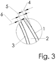
- each layer 1, 2, 3 has an essentially constant wall thickness 4, 5, 6, with all layers 1, 2, 3 also having essentially the same wall thicknesses 4, 5, 6. Because of the essentially constant wall thicknesses of each layer and because all layers have essentially the same wall thicknesses 4, 5, 6, the bellows can be produced simply and reliably by coextrusion.
- the foamed second layer 2 is of particular advantage. Due to the comparatively low density, material is saved in relation to the two adjoining layers 1, 3, so that the bellows shown can be manufactured inexpensively and is light.
Landscapes
- Engineering & Computer Science (AREA)
- Mechanical Engineering (AREA)
- General Engineering & Computer Science (AREA)
- Manufacturing & Machinery (AREA)
- Diaphragms And Bellows (AREA)
- Laminated Bodies (AREA)
- Sealing Devices (AREA)
Abstract
Description
- Die Erfindung betrifft einen Balg, dessen Verwendung und ein Verfahren zu seiner Herstellung.
- Bälge sind allgemein bekannt und bestehen häufig aus thermoplastischen Elastomeren. Die vorbekannten Bälge haben einen einschichtigen Aufbau und werden aus einem geblasenen Schlauch unter anderem durch Extrusionsblasformen hergestellt.
Durch den einschichtigen Aufbau kann ein Balg häufig nur unzureichend an die jeweiligen Gegebenheiten des Anwendungsfalles angepasst werden. Auch Teilbereiche eines einschichtigen Balgs bestehen zwangsläufig aus dem einen verwendeten Werkstoff, für die ein anderer Werkstoff vielleicht besser geeignet wäre, zum Beispiel hinsichtlich der Gebrauchseigenschaften, eines möglichst geringen Gewichts oder einer wirtschaftlicheren Herstellbarkeit. Insbesondere dann, wenn der verwendete Werkstoff teuer ist, wird auch der daraus hergestellte Balg teuer. - Der Erfindung liegt die Aufgabe zugrunde, einen Balg und ein Verfahren zu seiner Herstellung jeweils derart weiterzuentwickeln, dass der Balg gute Gebrauchseigenschaften während einer langen Gebrauchsdauer aufweist, besser an die jeweiligen Gegebenheiten des Anwendungsfalles angepasst werden kann und dass der Balg einfach und kostengünstig herstellbar ist. Außerdem soll eine Verwendung eines solchen Balgs genannt werden.
- Diese Aufgabe wird erfindungsgemäß durch die Merkmale der Ansprüche 1, 12 und 13 gelöst. Auf vorteilhafte Ausgestaltungen des Balgs nehmen die auf Anspruch 1 direkt oder indirekt rückbezogenen Ansprüche Bezug.
- Zur Lösung der Aufgabe ist ein Balg vorgesehen, mit einem zumindest zweischichtigen Aufbau, umfassend zumindest eine erste Schicht und zumindest eine zweite Schicht.
Hierbei ist von Vorteil, dass die unterschiedlichen Schichten des Balgs jeweils funktionstechnisch individualisiert sind. So gelangt zum Beispiel jeder Werkstoff nur für die Schicht zur Anwendung, für die er auch geeignet/erforderlich ist, um gute Gebrauchseigenschaften des Balgs während einer langen Gebrauchsdauer sicherzustellen. Die Verwendung eines zum Beispiel hinsichtlich Preis, Gewicht, Dauerhaltbarkeit überdimensionierten Werkstoffs ist durch den mehrschichtigen Aufbau des Balgs nicht mehr notwendig. Jede Schicht kann so ausgebildet werden, wie es für gute Gebrauchseigenschaften während einer langen Gebrauchsdauer erforderlich ist, unter besonderer Berücksichtigung einer wirtschaftlichen Herstellbarkeit. - Wird eine der Schichten, wie später noch erläutert werden wird, zum Beispiel aus einem Schaumstoff hergestellt, wird dadurch, im Vergleich zu einer Schicht aus einem ungeschäumten Werkstoff, Material eingespart, sodass der Balg insgesamt kostengünstiger und leichter herstellbar ist.
- Die Schichten sind herstellungsbedingt und werkstoffbedingt unlösbar miteinander verbunden. Dazu gelangen bevorzugt kompatible Werkstoffe zur Anwendung, zum Beispiel TPC-EE, -ET und -EE mit PBT oder TPV mit PP-Matrix.
Zum Beispiel hat TPC-EE mit PBT den Vorteil, dass diese Kombination besonders wärmebeständig, fest und dynamisch tauglich ist.
Zum Beispiel hat TPV mit PP-Matrix demgegenüber den Vorteil, dass diese Kombination besonders kostengünstig ist und für bestimmte Anwendungen ausreicht. - Durch eine solche Ausgestaltung ist die Handhabung des erfindungsgemäßen Balgs im Vergleich zu einem Balg mit einem nur einschichtigen Aufbau unverändert einfach. Insbesondere die Montage und die Demontage des Balgs, ebenso wie die Gebrauchseigenschaften des Balgs während seiner bestimmungsgemäßen Verwendung, unterscheiden sich, wenn nur vorteilhaft, nicht von guten einschichtig aufgebauten Bälgen.
- Die Schichten können aus voneinander abweichenden Werkstoffen bestehen und/oder voneinander abweichende Dichten aufweisen. Durch eine solche Ausgestaltung gibt es viele Variationsmöglichkeiten, so dass ein solcher Balg mit einem zumindest zweischichtigen Aufbau besonders gut an die jeweiligen Erfordernisse des Anwendungsfalls angepasst werden kann.
- Um das Recycling eines nicht mehr benötigten Balgs möglichst einfach durchführen zu können, ist es vorgesehen, dass die Schichten aus miteinander verträglichen Werkstoffen bestehen. Dies ist auch für eine gute Verbindung der Schichten von Vorteil. Solche miteinander verträglichen Werkstoffe sind zum Beispiel die Folgenden:
- PBT mit TPC-EE,
- PBT mit TPC-ET,
- PBT mit TPC-ES,
- PP mit TPV (PP/EPDM) und andere TPE auf PP-Basis,
- PA mit PA/ACM und PA/AEM und andere TPE auf PA-Basis,
- PA mit PEBA.
- Dabei sind:
- PA
- Polyamid
- ACM
- Polyacrylat-Kautschuk
- PEBA
- Polyetherblockamid
- PBT
- Polybutylenterephthalat
- AEM
- Polyacrylat-Ethylen-Kautschuk
- TPC
- thermoplastischer Copolymer
- EE
- Ether-Ester-Blockpolymer
- ET
- Ether-Ether-Blockpolymer
- ES
- Ester-Ester-Blockpolymer
- PP
- Polypropylen
- TPV
- thermoplastisches Vulkanisat
- EPDM
- Ethylen-Propylen-Dien-Kautschuk der M-Gruppe
- Die ersten drei Werkstoffkombinationen werden bevorzugt für Bälge an der Antriebswelle zur Abdichtung von Gleichlaufgelenken eingesetzt. Die übrigen Kombinationen finden eher bei Bälgen für die Lenkung oder sonstige Fahrwerkteile Anwendung. PP mit TPV eher bei geringeren Temperaturanforderungen, die Kombinationen mit PA bevorzugt bei hohen Temperaturanforderungen.
- Die genannten Werkstoffe sind deshalb, bezogen auf ihr Recycling und ihre Festigkeit, gut miteinander verträglich, weil sie chemisch ähnlich sind. Festigkeit und sonstige Eigenschaften des Rezyklats sind dann ähnlich denen der Werkstoffe der einzelnen Schichten.
- Besonders einfach recycelt werden können Bälge, deren Schichten aus demselben Werkstoff bestehen. Dadurch ist ein sortenreines Recycling möglich. Sinnvoll ist dies insbesondere, wenn zumindest eine der Schichten aus gleichem, aber geschäumtem Material besteht.
- Ein Werkstoff, der für die Herstellung von Bälgen in vielen Fällen besonders gut geeignet ist, ist ein TPE-Werkstoff. Bälge aus einem TPE-Werkstoff haben den Vorteil, dass sie im Vergleich zu herkömmlichen thermoplastischen Kunststoffen große Deformationen bei niedrigen Kräften zulassen.
- Deshalb ist es bevorzugt vorgesehen, dass zumindest eine der Schichten aus einem TPE-Werkstoff besteht.
- Generell können die erste und die zweite Schicht aus voneinander abweichenden Werkstoffen bestehen, wobei der Werkstoff von einer der Schichten ungeschäumt und von einer der Schichten geschäumt ist.
- Bevorzugt kann es jedoch vorgesehen sein, dass die erste Schicht und die zweite Schicht aus demselben Werkstoff bestehen, wobei der Werkstoff von einer der Schichten ungeschäumt und von einer der Schichten geschäumt ist. Für eine ungeschäumte Schicht ist, bei gleicher Dicke, vergleichsweise mehr Werkstoff erforderlich, als für eine geschäumte Schicht. Die ungeschäumte Schicht kann zum Beispiel die Außenschicht des Balgs bilden, die geschäumte Schicht demgegenüber die Innenschicht oder eine der Innenschichten. Die relativ empfindlichere geschäumte Schicht wird durch die ungeschäumte und widerstandsfähigere Außenschicht dann vor äußeren Einflüssen wirksam geschützt.
- Die Werkstoffeinsparung durch eine geschäumte Schicht im Vergleich zu einer ungeschäumten Schicht beträgt üblicherweise etwa 30 %, sodass der Balg kostengünstiger herstellbar ist, trotz der Werkstoffeinsparung aber die gleiche geforderte Wandstabilität aufweist. Das wird dadurch erreicht, dass das notwendige Widerstandsmoment einer zum Beispiel massiv-geschäumt-massiv aufgebauten Balgwand bei nur geringfügig erhöhter Wanddicke gleich einer Massiv-Schicht erreicht wird.
- Die geschäumte Schicht kann physikalisch oder chemisch geschäumt sein.
- Eine physikalisch geschäumte Schicht hat den Vorteil, dass kein Triebmittel eingesetzt werden muss, was in gewisser Weise den Kunststoff kontaminiert. Eine physikalische Schäumung erfolgt dadurch, dass während des Extrudierens in den erschmolzenen Werkstoff ein Gas, zum Beispiel Luft oder Stickstoff, injiziert wird.
- Eine chemisch geschäumte Schicht hat den Vorteil, dass das die Gas-Injektionseinheit an der Fertigungsanlage entfällt.
Eine chemisch Schäumung erfolgt dadurch, dass ein Triebmittel dem Kunststoff beigemengt wird. - Außerdem hat ein zumindest zweischichtiger Aufbau, der eine geschäumte Schicht umfasst, im Vergleich zu einem einschichtigen, ungeschäumten Aufbau den technischen Vorteil, dass solche Bälge eine verbesserte thermische Isolation aufweisen und nach wie vor rezyklierbar sind, wenn der Schaum aus dem gleichen Polymer wie die ungeschäumte Schicht besteht. Ein solcher Balg weist außerdem ein reduziertes Gewicht bei gleicher Stabilität auf, ist radial weicher und somit stoß-unempfindlicher und hat ein verbessertes Diffusionsverhalten, sofern geeignete Sperrschichten verwendet werden.
- Das verbesserte Diffusionsverhalten ist vorteilhaft, wenn zum Beispiel Fett in dem Balg ist und das Öl des Fetts durch Diffusion und damit dessen Schmiereigenschaften verloren geht. Eine geeignete Sperrschicht verhindert die Diffusion und erhält die Schmiereigenschaften des Fetts.
- Wie zuvor bereits beschrieben, kann die erste Schicht aus einem ungeschäumten Werkstoff bestehen und die zweite Schicht aus einem geschäumten Werkstoff. Um die zweite Schicht aus dem geschäumten Werkstoff bestmöglich vor unerwünschten Einflüssen zu schützen, kann es vorgesehen sein, dass die zweite Schicht zwischen der ersten Schicht und einer dritten Schicht sandwichartig angeordnet ist. Die geschäumte zweite Schicht kommt dann mit der inneren und äußeren Umgebung des Balgs nicht mehr in Berührung und ist bestmöglich geschützt.
- Die dritte Schicht und die erste Schicht können materialeinheitlich ausgebildet sein.
Am besten recycelbar ist ein Balg, bei dem alle Schichten aus einem übereinstimmenden Werkstoff bestehen, wobei der Werkstoff der ersten und der dritten Schicht bevorzugt ungeschäumt, der Werkstoff der zweiten Schicht demgegenüber bevorzugt geschäumt ist. - Hinsichtlich eines einfachen und prozesssicheren Verfahrens zur Herstellung des Balgs kann es vorgesehen sein, dass die erste Schicht und die dritte Schicht jeweils eine im Wesentlichen konstante Wandstärke aufweisen. Hierbei ist von Vorteil, dass alle Bereiche einer jeweiligen Schicht einfach und frei von herstellungsbedingten Fehlern herstellbar sind und der Balg deshalb gute und vorhersehbare Gebrauchseigenschaften während einer langen Gebrauchsdauer aufweist.
- Weiter ist von Vorteil, wenn die erste Schicht und die dritte Schicht im Wesentlichen gleiche Wandstärken aufweisen. Während des Herstellungsprozesses verhalten sich diese Schichten, zum Beispiel bezüglich Verfestigung und/oder Schrumpf, weitestgehend gleich.
- Die Wandstärke der zweiten Schicht ist bevorzugt größer als die Wandstärke der ersten und dritten Schicht, wenn die im Allgemeinen teuren Funktionsschichten außen liegen.
Die Wandstärke der zweiten Schicht ist bevorzugt kleiner als die äußeren, wenn sie eine hohe Festigkeit und einen höheren E-Modul hat als die äußeren Schichten. Sie hat dann einen die Festigkeit erhöhenden Charakter und beeinträchtigt die Flexibilität geringst möglich. Das gleiche gilt für Sperrschichten, die die Permeabilität verringern, wenn deren Werkstoff einen höheren E-Modul aufweist. - Für die meisten Anwendungsfälle, zum Beispiel im Bereich Kraftfahrzeug, haben die Schichten Wandstärken, die 0,3 mm bis 3 mm betragen.
Sind die Wandstärken dünner, ist die Haltbarkeit des Balgs während seiner bestimmungsgemäßen Verwendung eingeschränkt, sind die Wandstärken demgegenüber dicker, weist der Balg häufig nicht mehr die erforderliche Nachgiebigkeit auf. - Besonders vorteilhaft ist die Verwendung eines Balgs mit mehrschichtigem Aufbau als Achs- oder Lenkungsmanschette eines Kraftfahrzeugs. Besonders vorteilhaft deshalb, weil durch den mehrschichtigen Aufbau der Balg Schichten mit unterschiedlichen Eigenschaften erhalten kann und so die technischen Anforderungen bestmöglich erfüllt werden können. Die technischen Anforderungen sind geringes Gewicht, gute Wärmeisolierung, geringe Reibung, geringe Geräuschbildung, geringe Öl-Permeabilität, erhöhte Lebensdauer. Die genannten Vorteile können auch für andere Verwendungen von Vorteil sein, zum Beispiel für einen Balg für ein Lenkgetriebe eines Kraftfahrzeugs, einen Schutzbalg für ein Federbein eines Kraftfahrzeugs oder einen Anschlagbalg extern oder intern eines Federbeins eines Kraftfahrzeugs.
- Der Balg kann zusätzlich einen im Wesentlichen zylindrischen Bereich zur Stabilitätserhöhung aufweisen.
- Außerdem betrifft die Erfindung ein Verfahren zur Herstellung eines Balgs mit einem zumindest zweischichtigen Aufbau, umfassend zumindest eine erste Schicht und zumindest eine zweite Schicht, wobei alle Schichten in einem gemeinsamen Coextrusionswerkzeug zeitgleich durch Coextrusion hergestellt und herstellungsbedingt zum Balg zusammengeführt und in Verbindung mit der bereits als vorteilhaft genannten Werkstoffverträglichkeit dadurch unlösbar miteinander verbunden werden. Das Coextrudieren ist im Wesentlichen genauso einfach durchführbar wie das Extrusionsblasformen eines einwandigen Bauteils. Aufgeschmolzenes Polymer wird über eine Förderschnecke durch Düsen gepresst, sodass ein schlauchförmiges Halbzeug entsteht. Dieses schlauchförmige Halbzeug wird anschließend in einer Blasform aufgeblasen und dadurch an die Innenkontur der Blasform angepasst.
- Ein Ausführungsbeispiel eines erfindungsgemäßen Balgs wird nachfolgend anhand der
Figuren 1 bis 3 näher erläutert. - Diese zeigen jeweils in schematischer Darstellung:
- Figur 1
- eine perspektivische Ansicht eines gebrauchsfertigen, dreischichtigen Balgs,
- Figur 1a
- den Balg aus
Figur 1 mit einem herausgetrennten Ausschnitt, um den mehrschichtigen Aufbau besser zeigen zu können, - Figur 2
- einen vergrößerten Schnitt durch den dreischichtigen Balg aus
Figur 1 , - Figur 3
- einen weiter vergrößerten Ausschnitt aus dem Balg gemäß
Figur 2 . - In den
Figuren 1 bis 3 ist ein Ausführungsbeispiel eines erfindungsgemäßen Balgs gezeigt, der einen dreischichtigen Aufbau mit einer ersten 1, zweiten 2 und dritten Schicht 3 aufweist. -
Figur 1 zeigt eine perspektivische Ansicht des Balgs. Der Balg gelangt als Achsmanschette in einem Kraftfahrzeug zur Anwendung und ist als Faltenbalg ausgebildet. - In
Figur 1a ist der Balg ausFigur 1 mit einem herausgetrennten 90° Ausschnitt gezeigt. Dadurch ist der mehrschichtige Aufbau des Balgs zu sehen. - In
Figur 2 ist ein Schnitt durch eine Falte des Faltenbalgs ausFigur 1 gezeigt. Der Balg hat einen dreischichtigen Aufbau und umfasst die erste 1, die zweite 2 und die dritte Schicht 3. Alle drei Schichten 1, 2, 3 sind herstellungsbedingt unlösbar miteinander verbunden und bestehen aus einem übereinstimmenden TPE-Werkstoff.
Durch die materialeinheitliche Ausgestaltung des Balgs ist dieser problemlos und sortenrein recyclebar.
Alternativ bestehen die drei Schichten 1, 2, 3 aus verträglichen unterschiedlichen Werkstoffen mit den vorgenannten unterschiedlichen Eigenschaften. - Die erste Schicht 1 und die dritte Schicht 3 sind auf den einander abgewandten Seiten der zweiten Schicht 2 angeordnet, wobei der Balg sandwichartig aufgebaut ist. Die mittlere zweite Schicht 2 besteht aus einem geschäumten Werkstoff, während die erste Schicht 1 und die dritte Schicht 3 aus einem ungeschäumten Werkstoff bestehen. Die zweite Schicht 2 weist dadurch eine geringere Dichte als die beiden benachbarten Schichten 1, 3 auf.
- In
Figur 3 ist der Ausschnitt "X" ausFigur 2 vergrößert dargestellt.
Im gezeigten Ausführungsbeispiel weist jede Schicht 1, 2, 3 jeweils eine im Wesentlichen konstante Wandstärke 4, 5, 6 auf, wobei außerdem alle Schichten 1, 2, 3 im Wesentlichen gleiche Wandstärken 4, 5, 6 aufweisen. Durch die im Wesentlichen konstanten Wandstärken einer jeden Schicht und dadurch, dass alle Schichten im Wesentlichen gleiche Wandstärken 4, 5, 6 haben, ist der Balg durch Coextrusion einfach und prozesssicher herstellbar. - Insbesondere die geschäumte zweite Schicht 2 ist von hervorzuhebendem Vorteil. Durch die vergleichsweise geringe Dichte wird, bezogen auf die beiden angrenzenden Schichten 1, 3, Werkstoff eingespart, sodass der gezeigte Balg kostengünstig herstellbar und leicht ist.
Claims (13)
- Balg mit einem zumindest zweischichtigen Aufbau, umfassend zumindest eine erste Schicht (1) und zumindest eine zweite Schicht (2).
- Balg nach Anspruch 1, dadurch gekennzeichnet, dass die Schichten (1, 2) herstellungsbedingt unlösbar miteinander verbunden sind.
- Balg nach einem der Ansprüche 1 oder 2, dadurch gekennzeichnet, dass die Schichten (1, 2) aus voneinander abweichenden Werkstoffen bestehen und/oder voneinander abweichende Dichten aufweisen.
- Balg nach einem der Ansprüche 1 bis 3, dadurch gekennzeichnet, dass zumindest eine der Schichten (1, 2) aus einem TPE-Werkstoff besteht.
- Balg nach einem der Ansprüche 1 bis 4, dadurch gekennzeichnet, dass die erste Schicht (1) und die zweite Schicht (2) aus demselben Werkstoff bestehen und dass der Werkstoff von einer der Schichten (1, 2) ungeschäumt und von einer der Schichten (2, 1) geschäumt ist.
- Balg nach einem der Ansprüche 1 bis 5, dadurch gekennzeichnet, dass die erste Schicht (1) aus einem ungeschäumten Werkstoff besteht, dass die zweite Schicht (2) aus einem geschäumten Werkstoff besteht und dass die zweite Schicht (2) zwischen der ersten Schicht (1) und einer dritten Schicht (3) sandwichartig angeordnet ist.
- Balg nach Anspruch 6, dadurch gekennzeichnet, dass die dritte Schicht (3) materialeinheitlich mit der ersten Schicht (1) ausgebildet ist.
- Balg nach einem der Ansprüche 6 oder 7, dadurch gekennzeichnet, dass die erste Schicht (1) und die dritte Schicht (3) jeweils eine im Wesentlichen konstante Wandstärke (4, 6) aufweisen.
- Balg nach einem der Ansprüche 6 bis 8, dadurch gekennzeichnet, dass die erste Schicht (1) und die dritte Schicht (3) im Wesentlichen gleiche Wandstärken (4, 6) aufweisen.
- Balg nach einem der Ansprüche 6 bis 9, dadurch gekennzeichnet, dass die Wandstärke (5) der zweiten Schicht (2) größer als die Wandstärken (4, 6) der ersten Schicht (1) und der dritten Schicht (3) ist.
- Balg nach einem der Ansprüche 8 bis 10, dadurch gekennzeichnet, dass die Wandstärken (4, 5, 6) jeweils 0,3 mm bis 3 mm betragen.
- Verwendung eines Balgs nach einem der Ansprüche 1 bis 11 als Achs- oder Lenkungsmanschette eines Kraftfahrzeugs.
- Verfahren zur Herstellung eines Balgs mit einem zumindest zweischichtigen Aufbau, umfassend zumindest eine erste Schicht (1) und zumindest eine zweite Schicht (2), dadurch gekennzeichnet, dass alle Schichten (1, 2, 3) in einem gemeinsamen Coextrusionswerkzeug zeitgleich durch Coextrusion hergestellt und herstellungsbedingt zum Balg zusammengeführt und dadurch unlösbar miteinander verbunden werden.
Applications Claiming Priority (1)
| Application Number | Priority Date | Filing Date | Title |
|---|---|---|---|
| DE102019132692.3A DE102019132692A1 (de) | 2019-12-02 | 2019-12-02 | Balg, dessen Verwendung und Verfahren zu seiner Herstellung |
Publications (2)
| Publication Number | Publication Date |
|---|---|
| EP3832173A1 true EP3832173A1 (de) | 2021-06-09 |
| EP3832173B1 EP3832173B1 (de) | 2023-03-01 |
Family
ID=73740184
Family Applications (1)
| Application Number | Title | Priority Date | Filing Date |
|---|---|---|---|
| EP20210270.3A Active EP3832173B1 (de) | 2019-12-02 | 2020-11-27 | Balg, dessen verwendung und verfahren zu seiner herstellung |
Country Status (4)
| Country | Link |
|---|---|
| US (1) | US20210164565A1 (de) |
| EP (1) | EP3832173B1 (de) |
| CN (1) | CN112976699A (de) |
| DE (1) | DE102019132692A1 (de) |
Families Citing this family (2)
| Publication number | Priority date | Publication date | Assignee | Title |
|---|---|---|---|---|
| SE546713C2 (en) * | 2022-12-22 | 2025-02-11 | Husqvarna Ab | Robotic lawnmower and bellows element |
| DE102024200001A1 (de) * | 2024-01-02 | 2025-07-03 | Volkswagen Aktiengesellschaft | Stoßdämpfer für ein Kraftfahrzeug sowie Kraftfahrzeug |
Citations (2)
| Publication number | Priority date | Publication date | Assignee | Title |
|---|---|---|---|---|
| DE3236308A1 (de) * | 1981-09-30 | 1983-05-11 | Kyoraku Co., Ltd., Kyoto | Elastischer formgegenstand |
| DE10249073A1 (de) * | 2002-10-21 | 2004-05-06 | ZF Lemförder Metallwaren AG | Mehrschichtbalg |
Family Cites Families (6)
| Publication number | Priority date | Publication date | Assignee | Title |
|---|---|---|---|---|
| DE8001872U1 (de) * | 1980-04-24 | Karl Joh Gummiwarenfabrik Gmbh, 6460 Gelnhausen | Faltenbalg | |
| US6386551B1 (en) * | 1997-03-05 | 2002-05-14 | Trw Inc. | Plastic sleeve and method of manufacturing the same |
| JP4516680B2 (ja) * | 2000-09-28 | 2010-08-04 | 株式会社パイオラックス | コルゲートチューブ |
| JP4201638B2 (ja) * | 2003-04-28 | 2008-12-24 | 株式会社三洋化成 | コルゲート管の製造方法およびこの製造方法により製造されたコルゲート管 |
| US9038672B2 (en) * | 2010-12-02 | 2015-05-26 | Salflex Polymers Limited | Hollow article of variable wall structure density |
| DE102018214173A1 (de) * | 2017-08-23 | 2019-03-14 | Robert Bosch Gmbh | Faltenbalg für eine Hilfs- oder Fremdkraftlenkanlage in einem Kraftfahrzeug |
-
2019
- 2019-12-02 DE DE102019132692.3A patent/DE102019132692A1/de active Pending
-
2020
- 2020-10-27 CN CN202011160142.6A patent/CN112976699A/zh active Pending
- 2020-11-27 EP EP20210270.3A patent/EP3832173B1/de active Active
- 2020-12-02 US US17/109,183 patent/US20210164565A1/en not_active Abandoned
Patent Citations (2)
| Publication number | Priority date | Publication date | Assignee | Title |
|---|---|---|---|---|
| DE3236308A1 (de) * | 1981-09-30 | 1983-05-11 | Kyoraku Co., Ltd., Kyoto | Elastischer formgegenstand |
| DE10249073A1 (de) * | 2002-10-21 | 2004-05-06 | ZF Lemförder Metallwaren AG | Mehrschichtbalg |
Also Published As
| Publication number | Publication date |
|---|---|
| DE102019132692A1 (de) | 2021-06-02 |
| US20210164565A1 (en) | 2021-06-03 |
| CN112976699A (zh) | 2021-06-18 |
| EP3832173B1 (de) | 2023-03-01 |
Similar Documents
| Publication | Publication Date | Title |
|---|---|---|
| DE69518859T2 (de) | Wellenrohr, sowie verfahren zu seiner herstellung | |
| DE102008040548A1 (de) | Hydraulisch dämpfendes Buchsenlager | |
| DE102015212719A1 (de) | Mehrlagiges, geräuschabsorbierendes, geräuschdämmendes und luftdurchlässiges Material | |
| DE2605546A1 (de) | Blasform zur herstellung von aus hochelastischem kunststoff bestehenden faltenbaelgen | |
| EP3832173B1 (de) | Balg, dessen verwendung und verfahren zu seiner herstellung | |
| EP0679121B1 (de) | Im co-extrusions-blasverfahren hergestellter behälter | |
| DE69407011T2 (de) | Verfahren zur Herstellung einer Dichtung für Wälzlager, Dichtung für Wälzlager und mit einer solchen Dichtung versehenes Wälzlager | |
| DE102019120624A1 (de) | Spendervorrichtung und Verfahren zur Herstellung einer Spendervorrichtung | |
| WO2012117093A1 (de) | Bauteil für schienenfahrzeuge | |
| DE102005003945B4 (de) | Buchsenlager mit in Umfangsrichtung wechselnder radialer Steifigkeit | |
| DE112018002040T5 (de) | Klimagerätgehäuse | |
| DE202021004117U1 (de) | Thermisch gedämmtes Rohr | |
| DE10249073B4 (de) | Mehrschichtbalg | |
| EP3530450B1 (de) | Mehrschichtige kraftfahrzeug-rohrleitung | |
| EP1835216B1 (de) | Electrisch leitfähige Kraftfahrzeugrohrleitung aus Kunststoff | |
| DE4324000C2 (de) | Elastisches Gleitlager | |
| DE102008006545A1 (de) | Dichtung, insbesondere für ein Kraftfahrzeug, und Verahren zur Herstellung einer solchen Dichtung | |
| DE102010036976B4 (de) | Schottwanddurchführung | |
| DE19604613A1 (de) | Sandwichstruktur | |
| EP0974473B1 (de) | Balg oder Element eines Balges eines Überganges zwischen zwei gelenkig miteinander verbundenen Fahrzeugen | |
| DE4312538C2 (de) | Topf- oder Rollmembran | |
| DE102016014894A1 (de) | Filtermedium, Verfahren zu dessen Herstellung und Verwendung des Filtermediums in einem Filterelement | |
| DE19841397C1 (de) | Schlauch aus Kunststoff, der aus mehreren konzentrischen Schichten aufgebaut ist | |
| DE102018103190A1 (de) | Druckelastisches Abstandsbauteil sowie damit gebildeter belüfteter Fahrzeugsitz | |
| DE102024114228A1 (de) | Rohr zum Leiten von Kühlflüssigkeit zwischen zwei in einem kleinen Abstand zueinander angeordneten und sich quer zu dem Abstand relativ zueinander bewegenden Bauteilen |
Legal Events
| Date | Code | Title | Description |
|---|---|---|---|
| PUAI | Public reference made under article 153(3) epc to a published international application that has entered the european phase |
Free format text: ORIGINAL CODE: 0009012 |
|
| STAA | Information on the status of an ep patent application or granted ep patent |
Free format text: STATUS: THE APPLICATION HAS BEEN PUBLISHED |
|
| AK | Designated contracting states |
Kind code of ref document: A1 Designated state(s): AL AT BE BG CH CY CZ DE DK EE ES FI FR GB GR HR HU IE IS IT LI LT LU LV MC MK MT NL NO PL PT RO RS SE SI SK SM TR |
|
| STAA | Information on the status of an ep patent application or granted ep patent |
Free format text: STATUS: REQUEST FOR EXAMINATION WAS MADE |
|
| 17P | Request for examination filed |
Effective date: 20210623 |
|
| RBV | Designated contracting states (corrected) |
Designated state(s): AL AT BE BG CH CY CZ DE DK EE ES FI FR GB GR HR HU IE IS IT LI LT LU LV MC MK MT NL NO PL PT RO RS SE SI SK SM TR |
|
| REG | Reference to a national code |
Ref country code: DE Ref legal event code: R079 Ref document number: 502020002629 Country of ref document: DE Free format text: PREVIOUS MAIN CLASS: F16J0003040000 Ipc: B32B0005180000 |
|
| RIC1 | Information provided on ipc code assigned before grant |
Ipc: B29C 48/00 20190101ALI20220905BHEP Ipc: F16J 3/04 20060101ALI20220905BHEP Ipc: B29C 48/09 20190101ALI20220905BHEP Ipc: B29C 48/13 20190101ALI20220905BHEP Ipc: B32B 25/04 20060101ALI20220905BHEP Ipc: B29C 48/21 20190101ALI20220905BHEP Ipc: B29C 49/04 20060101ALI20220905BHEP Ipc: B32B 1/08 20060101ALI20220905BHEP Ipc: B32B 3/28 20060101ALI20220905BHEP Ipc: B32B 5/18 20060101AFI20220905BHEP |
|
| INTG | Intention to grant announced |
Effective date: 20221020 |
|
| GRAS | Grant fee paid |
Free format text: ORIGINAL CODE: EPIDOSNIGR3 |
|
| STAA | Information on the status of an ep patent application or granted ep patent |
Free format text: STATUS: GRANT OF PATENT IS INTENDED |
|
| GRAA | (expected) grant |
Free format text: ORIGINAL CODE: 0009210 |
|
| STAA | Information on the status of an ep patent application or granted ep patent |
Free format text: STATUS: THE PATENT HAS BEEN GRANTED |
|
| AK | Designated contracting states |
Kind code of ref document: B1 Designated state(s): AL AT BE BG CH CY CZ DE DK EE ES FI FR GB GR HR HU IE IS IT LI LT LU LV MC MK MT NL NO PL PT RO RS SE SI SK SM TR |
|
| REG | Reference to a national code |
Ref country code: GB Ref legal event code: FG4D Free format text: NOT ENGLISH |
|
| REG | Reference to a national code |
Ref country code: CH Ref legal event code: EP Ref country code: AT Ref legal event code: REF Ref document number: 1550706 Country of ref document: AT Kind code of ref document: T Effective date: 20230315 |
|
| REG | Reference to a national code |
Ref country code: DE Ref legal event code: R096 Ref document number: 502020002629 Country of ref document: DE |
|
| REG | Reference to a national code |
Ref country code: IE Ref legal event code: FG4D Free format text: LANGUAGE OF EP DOCUMENT: GERMAN |
|
| REG | Reference to a national code |
Ref country code: LT Ref legal event code: MG9D |
|
| REG | Reference to a national code |
Ref country code: NL Ref legal event code: MP Effective date: 20230301 |
|
| P01 | Opt-out of the competence of the unified patent court (upc) registered |
Effective date: 20230606 |
|
| PG25 | Lapsed in a contracting state [announced via postgrant information from national office to epo] |
Ref country code: RS Free format text: LAPSE BECAUSE OF FAILURE TO SUBMIT A TRANSLATION OF THE DESCRIPTION OR TO PAY THE FEE WITHIN THE PRESCRIBED TIME-LIMIT Effective date: 20230301 Ref country code: NO Free format text: LAPSE BECAUSE OF FAILURE TO SUBMIT A TRANSLATION OF THE DESCRIPTION OR TO PAY THE FEE WITHIN THE PRESCRIBED TIME-LIMIT Effective date: 20230601 Ref country code: LV Free format text: LAPSE BECAUSE OF FAILURE TO SUBMIT A TRANSLATION OF THE DESCRIPTION OR TO PAY THE FEE WITHIN THE PRESCRIBED TIME-LIMIT Effective date: 20230301 Ref country code: LT Free format text: LAPSE BECAUSE OF FAILURE TO SUBMIT A TRANSLATION OF THE DESCRIPTION OR TO PAY THE FEE WITHIN THE PRESCRIBED TIME-LIMIT Effective date: 20230301 Ref country code: HR Free format text: LAPSE BECAUSE OF FAILURE TO SUBMIT A TRANSLATION OF THE DESCRIPTION OR TO PAY THE FEE WITHIN THE PRESCRIBED TIME-LIMIT Effective date: 20230301 Ref country code: ES Free format text: LAPSE BECAUSE OF FAILURE TO SUBMIT A TRANSLATION OF THE DESCRIPTION OR TO PAY THE FEE WITHIN THE PRESCRIBED TIME-LIMIT Effective date: 20230301 |
|
| PG25 | Lapsed in a contracting state [announced via postgrant information from national office to epo] |
Ref country code: SE Free format text: LAPSE BECAUSE OF FAILURE TO SUBMIT A TRANSLATION OF THE DESCRIPTION OR TO PAY THE FEE WITHIN THE PRESCRIBED TIME-LIMIT Effective date: 20230301 Ref country code: PL Free format text: LAPSE BECAUSE OF FAILURE TO SUBMIT A TRANSLATION OF THE DESCRIPTION OR TO PAY THE FEE WITHIN THE PRESCRIBED TIME-LIMIT Effective date: 20230301 Ref country code: NL Free format text: LAPSE BECAUSE OF FAILURE TO SUBMIT A TRANSLATION OF THE DESCRIPTION OR TO PAY THE FEE WITHIN THE PRESCRIBED TIME-LIMIT Effective date: 20230301 Ref country code: GR Free format text: LAPSE BECAUSE OF FAILURE TO SUBMIT A TRANSLATION OF THE DESCRIPTION OR TO PAY THE FEE WITHIN THE PRESCRIBED TIME-LIMIT Effective date: 20230602 Ref country code: FI Free format text: LAPSE BECAUSE OF FAILURE TO SUBMIT A TRANSLATION OF THE DESCRIPTION OR TO PAY THE FEE WITHIN THE PRESCRIBED TIME-LIMIT Effective date: 20230301 |
|
| PG25 | Lapsed in a contracting state [announced via postgrant information from national office to epo] |
Ref country code: SM Free format text: LAPSE BECAUSE OF FAILURE TO SUBMIT A TRANSLATION OF THE DESCRIPTION OR TO PAY THE FEE WITHIN THE PRESCRIBED TIME-LIMIT Effective date: 20230301 Ref country code: RO Free format text: LAPSE BECAUSE OF FAILURE TO SUBMIT A TRANSLATION OF THE DESCRIPTION OR TO PAY THE FEE WITHIN THE PRESCRIBED TIME-LIMIT Effective date: 20230301 Ref country code: PT Free format text: LAPSE BECAUSE OF FAILURE TO SUBMIT A TRANSLATION OF THE DESCRIPTION OR TO PAY THE FEE WITHIN THE PRESCRIBED TIME-LIMIT Effective date: 20230703 Ref country code: EE Free format text: LAPSE BECAUSE OF FAILURE TO SUBMIT A TRANSLATION OF THE DESCRIPTION OR TO PAY THE FEE WITHIN THE PRESCRIBED TIME-LIMIT Effective date: 20230301 Ref country code: CZ Free format text: LAPSE BECAUSE OF FAILURE TO SUBMIT A TRANSLATION OF THE DESCRIPTION OR TO PAY THE FEE WITHIN THE PRESCRIBED TIME-LIMIT Effective date: 20230301 |
|
| PG25 | Lapsed in a contracting state [announced via postgrant information from national office to epo] |
Ref country code: SK Free format text: LAPSE BECAUSE OF FAILURE TO SUBMIT A TRANSLATION OF THE DESCRIPTION OR TO PAY THE FEE WITHIN THE PRESCRIBED TIME-LIMIT Effective date: 20230301 Ref country code: IS Free format text: LAPSE BECAUSE OF FAILURE TO SUBMIT A TRANSLATION OF THE DESCRIPTION OR TO PAY THE FEE WITHIN THE PRESCRIBED TIME-LIMIT Effective date: 20230701 |
|
| REG | Reference to a national code |
Ref country code: DE Ref legal event code: R097 Ref document number: 502020002629 Country of ref document: DE |
|
| PLBE | No opposition filed within time limit |
Free format text: ORIGINAL CODE: 0009261 |
|
| STAA | Information on the status of an ep patent application or granted ep patent |
Free format text: STATUS: NO OPPOSITION FILED WITHIN TIME LIMIT |
|
| PG25 | Lapsed in a contracting state [announced via postgrant information from national office to epo] |
Ref country code: SI Free format text: LAPSE BECAUSE OF FAILURE TO SUBMIT A TRANSLATION OF THE DESCRIPTION OR TO PAY THE FEE WITHIN THE PRESCRIBED TIME-LIMIT Effective date: 20230301 Ref country code: DK Free format text: LAPSE BECAUSE OF FAILURE TO SUBMIT A TRANSLATION OF THE DESCRIPTION OR TO PAY THE FEE WITHIN THE PRESCRIBED TIME-LIMIT Effective date: 20230301 |
|
| 26N | No opposition filed |
Effective date: 20231204 |
|
| PG25 | Lapsed in a contracting state [announced via postgrant information from national office to epo] |
Ref country code: IT Free format text: LAPSE BECAUSE OF FAILURE TO SUBMIT A TRANSLATION OF THE DESCRIPTION OR TO PAY THE FEE WITHIN THE PRESCRIBED TIME-LIMIT Effective date: 20230301 |
|
| REG | Reference to a national code |
Ref country code: CH Ref legal event code: PL |
|
| PG25 | Lapsed in a contracting state [announced via postgrant information from national office to epo] |
Ref country code: MC Free format text: LAPSE BECAUSE OF FAILURE TO SUBMIT A TRANSLATION OF THE DESCRIPTION OR TO PAY THE FEE WITHIN THE PRESCRIBED TIME-LIMIT Effective date: 20230301 |
|
| PG25 | Lapsed in a contracting state [announced via postgrant information from national office to epo] |
Ref country code: LU Free format text: LAPSE BECAUSE OF NON-PAYMENT OF DUE FEES Effective date: 20231127 |
|
| PG25 | Lapsed in a contracting state [announced via postgrant information from national office to epo] |
Ref country code: CH Free format text: LAPSE BECAUSE OF NON-PAYMENT OF DUE FEES Effective date: 20231130 |
|
| PG25 | Lapsed in a contracting state [announced via postgrant information from national office to epo] |
Ref country code: MC Free format text: LAPSE BECAUSE OF FAILURE TO SUBMIT A TRANSLATION OF THE DESCRIPTION OR TO PAY THE FEE WITHIN THE PRESCRIBED TIME-LIMIT Effective date: 20230301 Ref country code: LU Free format text: LAPSE BECAUSE OF NON-PAYMENT OF DUE FEES Effective date: 20231127 Ref country code: CH Free format text: LAPSE BECAUSE OF NON-PAYMENT OF DUE FEES Effective date: 20231130 |
|
| REG | Reference to a national code |
Ref country code: BE Ref legal event code: MM Effective date: 20231130 |
|
| REG | Reference to a national code |
Ref country code: IE Ref legal event code: MM4A |
|
| PG25 | Lapsed in a contracting state [announced via postgrant information from national office to epo] |
Ref country code: IE Free format text: LAPSE BECAUSE OF NON-PAYMENT OF DUE FEES Effective date: 20231127 |
|
| PG25 | Lapsed in a contracting state [announced via postgrant information from national office to epo] |
Ref country code: BE Free format text: LAPSE BECAUSE OF NON-PAYMENT OF DUE FEES Effective date: 20231130 |
|
| PG25 | Lapsed in a contracting state [announced via postgrant information from national office to epo] |
Ref country code: IE Free format text: LAPSE BECAUSE OF NON-PAYMENT OF DUE FEES Effective date: 20231127 Ref country code: BE Free format text: LAPSE BECAUSE OF NON-PAYMENT OF DUE FEES Effective date: 20231130 |
|
| PG25 | Lapsed in a contracting state [announced via postgrant information from national office to epo] |
Ref country code: BG Free format text: LAPSE BECAUSE OF FAILURE TO SUBMIT A TRANSLATION OF THE DESCRIPTION OR TO PAY THE FEE WITHIN THE PRESCRIBED TIME-LIMIT Effective date: 20230301 |
|
| PG25 | Lapsed in a contracting state [announced via postgrant information from national office to epo] |
Ref country code: BG Free format text: LAPSE BECAUSE OF FAILURE TO SUBMIT A TRANSLATION OF THE DESCRIPTION OR TO PAY THE FEE WITHIN THE PRESCRIBED TIME-LIMIT Effective date: 20230301 |
|
| PG25 | Lapsed in a contracting state [announced via postgrant information from national office to epo] |
Ref country code: CY Free format text: LAPSE BECAUSE OF FAILURE TO SUBMIT A TRANSLATION OF THE DESCRIPTION OR TO PAY THE FEE WITHIN THE PRESCRIBED TIME-LIMIT; INVALID AB INITIO Effective date: 20201127 |
|
| PG25 | Lapsed in a contracting state [announced via postgrant information from national office to epo] |
Ref country code: HU Free format text: LAPSE BECAUSE OF FAILURE TO SUBMIT A TRANSLATION OF THE DESCRIPTION OR TO PAY THE FEE WITHIN THE PRESCRIBED TIME-LIMIT; INVALID AB INITIO Effective date: 20201127 |
|
| PG25 | Lapsed in a contracting state [announced via postgrant information from national office to epo] |
Ref country code: TR Free format text: LAPSE BECAUSE OF FAILURE TO SUBMIT A TRANSLATION OF THE DESCRIPTION OR TO PAY THE FEE WITHIN THE PRESCRIBED TIME-LIMIT Effective date: 20230301 |
|
| PGFP | Annual fee paid to national office [announced via postgrant information from national office to epo] |
Ref country code: DE Payment date: 20251126 Year of fee payment: 6 |
|
| PGFP | Annual fee paid to national office [announced via postgrant information from national office to epo] |
Ref country code: GB Payment date: 20251125 Year of fee payment: 6 |
|
| PGFP | Annual fee paid to national office [announced via postgrant information from national office to epo] |
Ref country code: AT Payment date: 20260113 Year of fee payment: 5 |
|
| PGFP | Annual fee paid to national office [announced via postgrant information from national office to epo] |
Ref country code: FR Payment date: 20251124 Year of fee payment: 6 |