EP3530450B1 - Mehrschichtige kraftfahrzeug-rohrleitung - Google Patents
Mehrschichtige kraftfahrzeug-rohrleitung Download PDFInfo
- Publication number
- EP3530450B1 EP3530450B1 EP18171614.3A EP18171614A EP3530450B1 EP 3530450 B1 EP3530450 B1 EP 3530450B1 EP 18171614 A EP18171614 A EP 18171614A EP 3530450 B1 EP3530450 B1 EP 3530450B1
- Authority
- EP
- European Patent Office
- Prior art keywords
- layer
- thickness
- polyamide
- motor vehicle
- adhesion promoting
- Prior art date
- Legal status (The legal status is an assumption and is not a legal conclusion. Google has not performed a legal analysis and makes no representation as to the accuracy of the status listed.)
- Active
Links
Images
Classifications
-
- F—MECHANICAL ENGINEERING; LIGHTING; HEATING; WEAPONS; BLASTING
- F16—ENGINEERING ELEMENTS AND UNITS; GENERAL MEASURES FOR PRODUCING AND MAINTAINING EFFECTIVE FUNCTIONING OF MACHINES OR INSTALLATIONS; THERMAL INSULATION IN GENERAL
- F16L—PIPES; JOINTS OR FITTINGS FOR PIPES; SUPPORTS FOR PIPES, CABLES OR PROTECTIVE TUBING; MEANS FOR THERMAL INSULATION IN GENERAL
- F16L11/00—Hoses, i.e. flexible pipes
- F16L11/04—Hoses, i.e. flexible pipes made of rubber or flexible plastics
- F16L11/10—Hoses, i.e. flexible pipes made of rubber or flexible plastics with reinforcements not embedded in the wall
-
- B—PERFORMING OPERATIONS; TRANSPORTING
- B32—LAYERED PRODUCTS
- B32B—LAYERED PRODUCTS, i.e. PRODUCTS BUILT-UP OF STRATA OF FLAT OR NON-FLAT, e.g. CELLULAR OR HONEYCOMB, FORM
- B32B1/00—Layered products having a general shape other than plane
- B32B1/08—Tubular products
-
- B—PERFORMING OPERATIONS; TRANSPORTING
- B32—LAYERED PRODUCTS
- B32B—LAYERED PRODUCTS, i.e. PRODUCTS BUILT-UP OF STRATA OF FLAT OR NON-FLAT, e.g. CELLULAR OR HONEYCOMB, FORM
- B32B27/00—Layered products comprising a layer of synthetic resin
- B32B27/06—Layered products comprising a layer of synthetic resin as the main or only constituent of a layer, which is next to another layer of the same or of a different material
- B32B27/08—Layered products comprising a layer of synthetic resin as the main or only constituent of a layer, which is next to another layer of the same or of a different material of synthetic resin
-
- B—PERFORMING OPERATIONS; TRANSPORTING
- B32—LAYERED PRODUCTS
- B32B—LAYERED PRODUCTS, i.e. PRODUCTS BUILT-UP OF STRATA OF FLAT OR NON-FLAT, e.g. CELLULAR OR HONEYCOMB, FORM
- B32B27/00—Layered products comprising a layer of synthetic resin
- B32B27/32—Layered products comprising a layer of synthetic resin comprising polyolefins
- B32B27/322—Layered products comprising a layer of synthetic resin comprising polyolefins comprising halogenated polyolefins, e.g. PTFE
-
- B—PERFORMING OPERATIONS; TRANSPORTING
- B32—LAYERED PRODUCTS
- B32B—LAYERED PRODUCTS, i.e. PRODUCTS BUILT-UP OF STRATA OF FLAT OR NON-FLAT, e.g. CELLULAR OR HONEYCOMB, FORM
- B32B27/00—Layered products comprising a layer of synthetic resin
- B32B27/34—Layered products comprising a layer of synthetic resin comprising polyamides
-
- B—PERFORMING OPERATIONS; TRANSPORTING
- B32—LAYERED PRODUCTS
- B32B—LAYERED PRODUCTS, i.e. PRODUCTS BUILT-UP OF STRATA OF FLAT OR NON-FLAT, e.g. CELLULAR OR HONEYCOMB, FORM
- B32B7/00—Layered products characterised by the relation between layers; Layered products characterised by the relative orientation of features between layers, or by the relative values of a measurable parameter between layers, i.e. products comprising layers having different physical, chemical or physicochemical properties; Layered products characterised by the interconnection of layers
- B32B7/04—Interconnection of layers
- B32B7/12—Interconnection of layers using interposed adhesives or interposed materials with bonding properties
-
- F—MECHANICAL ENGINEERING; LIGHTING; HEATING; WEAPONS; BLASTING
- F16—ENGINEERING ELEMENTS AND UNITS; GENERAL MEASURES FOR PRODUCING AND MAINTAINING EFFECTIVE FUNCTIONING OF MACHINES OR INSTALLATIONS; THERMAL INSULATION IN GENERAL
- F16L—PIPES; JOINTS OR FITTINGS FOR PIPES; SUPPORTS FOR PIPES, CABLES OR PROTECTIVE TUBING; MEANS FOR THERMAL INSULATION IN GENERAL
- F16L11/00—Hoses, i.e. flexible pipes
- F16L11/04—Hoses, i.e. flexible pipes made of rubber or flexible plastics
- F16L11/045—Hoses, i.e. flexible pipes made of rubber or flexible plastics with four or more layers without reinforcement
-
- B—PERFORMING OPERATIONS; TRANSPORTING
- B32—LAYERED PRODUCTS
- B32B—LAYERED PRODUCTS, i.e. PRODUCTS BUILT-UP OF STRATA OF FLAT OR NON-FLAT, e.g. CELLULAR OR HONEYCOMB, FORM
- B32B2250/00—Layers arrangement
- B32B2250/05—5 or more layers
-
- B—PERFORMING OPERATIONS; TRANSPORTING
- B32—LAYERED PRODUCTS
- B32B—LAYERED PRODUCTS, i.e. PRODUCTS BUILT-UP OF STRATA OF FLAT OR NON-FLAT, e.g. CELLULAR OR HONEYCOMB, FORM
- B32B2250/00—Layers arrangement
- B32B2250/24—All layers being polymeric
-
- B—PERFORMING OPERATIONS; TRANSPORTING
- B32—LAYERED PRODUCTS
- B32B—LAYERED PRODUCTS, i.e. PRODUCTS BUILT-UP OF STRATA OF FLAT OR NON-FLAT, e.g. CELLULAR OR HONEYCOMB, FORM
- B32B2274/00—Thermoplastic elastomer material
-
- B—PERFORMING OPERATIONS; TRANSPORTING
- B32—LAYERED PRODUCTS
- B32B—LAYERED PRODUCTS, i.e. PRODUCTS BUILT-UP OF STRATA OF FLAT OR NON-FLAT, e.g. CELLULAR OR HONEYCOMB, FORM
- B32B2307/00—Properties of the layers or laminate
- B32B2307/30—Properties of the layers or laminate having particular thermal properties
- B32B2307/306—Resistant to heat
-
- B—PERFORMING OPERATIONS; TRANSPORTING
- B32—LAYERED PRODUCTS
- B32B—LAYERED PRODUCTS, i.e. PRODUCTS BUILT-UP OF STRATA OF FLAT OR NON-FLAT, e.g. CELLULAR OR HONEYCOMB, FORM
- B32B2307/00—Properties of the layers or laminate
- B32B2307/70—Other properties
- B32B2307/714—Inert, i.e. inert to chemical degradation, corrosion
-
- B—PERFORMING OPERATIONS; TRANSPORTING
- B32—LAYERED PRODUCTS
- B32B—LAYERED PRODUCTS, i.e. PRODUCTS BUILT-UP OF STRATA OF FLAT OR NON-FLAT, e.g. CELLULAR OR HONEYCOMB, FORM
- B32B2307/00—Properties of the layers or laminate
- B32B2307/70—Other properties
- B32B2307/724—Permeability to gases, adsorption
- B32B2307/7242—Non-permeable
-
- B—PERFORMING OPERATIONS; TRANSPORTING
- B32—LAYERED PRODUCTS
- B32B—LAYERED PRODUCTS, i.e. PRODUCTS BUILT-UP OF STRATA OF FLAT OR NON-FLAT, e.g. CELLULAR OR HONEYCOMB, FORM
- B32B2307/00—Properties of the layers or laminate
- B32B2307/70—Other properties
- B32B2307/732—Dimensional properties
-
- B—PERFORMING OPERATIONS; TRANSPORTING
- B32—LAYERED PRODUCTS
- B32B—LAYERED PRODUCTS, i.e. PRODUCTS BUILT-UP OF STRATA OF FLAT OR NON-FLAT, e.g. CELLULAR OR HONEYCOMB, FORM
- B32B2325/00—Polymers of vinyl-aromatic compounds, e.g. polystyrene
-
- B—PERFORMING OPERATIONS; TRANSPORTING
- B32—LAYERED PRODUCTS
- B32B—LAYERED PRODUCTS, i.e. PRODUCTS BUILT-UP OF STRATA OF FLAT OR NON-FLAT, e.g. CELLULAR OR HONEYCOMB, FORM
- B32B2377/00—Polyamides
-
- B—PERFORMING OPERATIONS; TRANSPORTING
- B32—LAYERED PRODUCTS
- B32B—LAYERED PRODUCTS, i.e. PRODUCTS BUILT-UP OF STRATA OF FLAT OR NON-FLAT, e.g. CELLULAR OR HONEYCOMB, FORM
- B32B2597/00—Tubular articles, e.g. hoses, pipes
-
- B—PERFORMING OPERATIONS; TRANSPORTING
- B32—LAYERED PRODUCTS
- B32B—LAYERED PRODUCTS, i.e. PRODUCTS BUILT-UP OF STRATA OF FLAT OR NON-FLAT, e.g. CELLULAR OR HONEYCOMB, FORM
- B32B2605/00—Vehicles
- B32B2605/08—Cars
-
- B—PERFORMING OPERATIONS; TRANSPORTING
- B32—LAYERED PRODUCTS
- B32B—LAYERED PRODUCTS, i.e. PRODUCTS BUILT-UP OF STRATA OF FLAT OR NON-FLAT, e.g. CELLULAR OR HONEYCOMB, FORM
- B32B27/00—Layered products comprising a layer of synthetic resin
- B32B27/30—Layered products comprising a layer of synthetic resin comprising vinyl (co)polymers; comprising acrylic (co)polymers
- B32B27/306—Layered products comprising a layer of synthetic resin comprising vinyl (co)polymers; comprising acrylic (co)polymers comprising vinyl acetate or vinyl alcohol (co)polymers
-
- B—PERFORMING OPERATIONS; TRANSPORTING
- B32—LAYERED PRODUCTS
- B32B—LAYERED PRODUCTS, i.e. PRODUCTS BUILT-UP OF STRATA OF FLAT OR NON-FLAT, e.g. CELLULAR OR HONEYCOMB, FORM
- B32B27/00—Layered products comprising a layer of synthetic resin
- B32B27/32—Layered products comprising a layer of synthetic resin comprising polyolefins
-
- F—MECHANICAL ENGINEERING; LIGHTING; HEATING; WEAPONS; BLASTING
- F16—ENGINEERING ELEMENTS AND UNITS; GENERAL MEASURES FOR PRODUCING AND MAINTAINING EFFECTIVE FUNCTIONING OF MACHINES OR INSTALLATIONS; THERMAL INSULATION IN GENERAL
- F16L—PIPES; JOINTS OR FITTINGS FOR PIPES; SUPPORTS FOR PIPES, CABLES OR PROTECTIVE TUBING; MEANS FOR THERMAL INSULATION IN GENERAL
- F16L11/00—Hoses, i.e. flexible pipes
- F16L11/04—Hoses, i.e. flexible pipes made of rubber or flexible plastics
- F16L2011/047—Hoses, i.e. flexible pipes made of rubber or flexible plastics with a diffusion barrier layer
Definitions
- the invention relates to a multilayer motor vehicle pipeline for the passage of a fluid medium, in particular for the passage of fuels, the pipeline having at least five layers.
- the multilayer motor vehicle pipeline according to the invention is used in particular as a fuel pipeline in vehicles or motor vehicles.
- the motor vehicle pipeline can also be used as a ventilation line in tank ventilation systems. With this use, the pipeline is particularly exposed to fuel vapors and their condensates.
- the motor vehicle pipeline according to the invention can also be used for other purposes, for example as a line for cooling and tempering media.
- Multilayer motor vehicle pipelines of the type mentioned at the outset are known in practice in various embodiments. Many of these known pipelines have the disadvantage that they are exposed to undesired washing out of pipeline components when fuel is passed through. This applies above all to the inner layer in contact with the fuel, but also to the adjacent middle layers. In many known motor vehicle pipelines, oligomers and similar substance constituents are washed out of the fuel from the layers, and these substances are then disadvantageously deposited in the fuel system. This can lead to problems, for example with nozzles and similar components. For these reasons, many known pipelines leave something to be desired in terms of their resistance to the fuels. As a result, the barrier properties of these pipelines often do not meet the requirements.
- a pipeline is to be specified which is sufficiently resistant to chemical stresses from components contained in the fuels and which is characterized in particular by a lower permeability for alcohols contained in the fuel.
- a number of material options are specified for both the outer layer and the inner layer of this pipeline.
- the pipeline necessarily has a first carrier layer made of polyamide and a second carrier layer made of polyamide.
- a tank inner pipe which is used in fuel tanks of motor vehicles.
- the pipeline has a tube wall composed of at least three layers, an outer layer based on an aromatic polyamide, an intermediate layer based on polyamide and an inner layer based on an aromatic polyamide being provided. Intermediate adhesive layers are possible.
- the invention is based on the technical problem of specifying a multilayer motor vehicle pipeline of the type mentioned at the outset, in which the disadvantages described at the outset can be effectively avoided and which, above all, has a high resistance to leaching and additionally has sufficient mechanical resistance and optimal thermal resistance .
- the multilayer motor vehicle pipeline should also be sufficiently resistant to external corrosive influences or to corrosive media, for example metal chlorides.
- an outer layer of at least one polyamide is provided.
- the outer layer made of at least one polyamide means that the outer layer consists of at least one polyamide or essentially consists of at least one polyamide.
- a particularly preferred embodiment of the invention is characterized in that the outer layer consists of polyamide 12 and / or polyamide 6.12 or essentially polyamide 12 and / or polyamide 6.12. It is recommended that the thickness of the outer layer is 5 to 50%, preferably 5 to 45% and in particular 7 to 40% of the total layer thickness of the pipeline. The maximum thickness of the outer layer is recommended to be 0.4 mm.
- the thickness of the outer layer is expediently between 0.1 and 0.4 mm, preferably between 0.2 and 0.4 mm.
- At least one first adhesion promoter layer is provided between the outer layer and the barrier layer.
- the first adhesion promoter layer is arranged between the outer layer and the barrier layer, and the first adhesion promoter layer is directly connected to the outer layer on the one hand and directly to the barrier layer on the other hand.
- An adhesion promoter layer based on at least one polyamide and / or based on at least one polyolefin is expediently used. If an adhesion promoter layer based on polyamide is used, it is recommended that it be a modified polyamide, and preferably a modified polyamide based on polyamide 6.12.
- an adhesion promoter layer based on polypropylene is recommended.
- the polypropylene is expediently a modified polypropylene which has been modified, for example, with a carboxylic acid derivative. It is within the scope of the invention that the thickness of the first adhesion promoter layer is 3 to 30%, preferably 5 to 20% and preferably 5 to 15% of the total layer thickness of the pipeline.
- the thickness of the first adhesion promoter layer is expediently 0.03 to 0.15 mm and in particular 0.03 to 0.1 mm.
- the barrier layer is a barrier layer based on at least one component from the group "EVOH, fluoropolymer".
- EVOH means ethylene-vinyl alcohol copolymer.
- the barrier layer consists of EVOH or essentially EVOH.
- the barrier layer consists of at least one fluoropolymer or essentially of at least one fluoropolymer.
- the barrier layer particularly preferably consists of only one fluoropolymer or essentially only of one fluoropolymer.
- the thickness of the barrier layer is preferably 5 to 50%, preferably 10 to 40% and in particular 10 to 35% of the total layer thickness Pipe according to the invention. It is within the scope of the invention that the barrier layer has barrier properties with respect to at least one component of a fuel passed through the pipeline.
- At least one second adhesion promoter layer and, according to one embodiment, only a second adhesion promoter layer are arranged between the barrier layer and the inner layer of the pipeline according to the invention.
- the second adhesion promoter layer is expediently an adhesion promoter layer based on at least one polyamide and / or based on at least one polyolefin. If a second adhesion promoter layer based on at least one polyamide is used, it is recommended to use an adhesion promoter layer based on polyamide 6.12.
- a modified polyamide and in particular a modified polyamide based on polyamide 6.12 is expediently used for the second adhesion promoter layer.
- an adhesion promoter layer based on polypropylene is preferably used, and in particular based on a modified polypropylene.
- the polypropylene is modified, for example, with a carboxylic acid derivative.
- the thickness of the second adhesion promoter layer is 3 to 20%, preferably 5 to 20% and in particular 5 to 15% of the total layer thickness of the pipeline.
- the thickness of the second adhesion promoter layer is preferably 0.03 to 0.15 mm and in particular 0.03 to 0.1 mm.
- an inner layer made of at least one thermoplastic polyurethane (TPU) and / or made of at least one partially aromatic polyamide (PPA) is used. It is also within the scope of the invention that the inner layer consists of at least one thermoplastic polyurethane (TPU) consists or essentially consists of at least one thermoplastic polyurethane (TPU) and / or consists of at least one partially aromatic polyamide (PPA) or essentially consists of at least one partially aromatic polyamide (PPA). According to one embodiment, the inner layer consists only of a thermoplastic polyurethane (TPU) or essentially only of a thermoplastic polyurethane (TPU).
- the thickness of the inner layer is 5 to 50%, preferably 5 to 45% and preferably 7 to 40% of the total layer thickness of the pipeline.
- the thickness of the inner layer is preferably 0.05 to 0.45 mm, preferably 0.05 to 0.4 mm and in particular 0.1 to 0.35 mm.
- the inner layer of the pipeline is provided with conductivity additives. It is within the scope of the invention that the inner layer is the innermost layer of the pipeline and is thus in contact with the medium flowing through the pipeline or with the fuel flowing through the pipeline.
- An expedient embodiment of the invention is characterized in that the thickness of the first adhesion promoter layer and / or the thickness of the second adhesion promoter layer is less than the thickness of the outer layer.
- the thickness of the first adhesion promoter layer and the thickness of the second adhesion promoter layer are less than the thickness of the barrier layer.
- the thickness of the first adhesion promoter layer and / or the thickness of the second adhesion promoter layer is preferably less than the thickness of the inner layer.
- the thickness of the outer layer is greater than the thickness of the barrier layer and / or greater than the thickness of the inner layer.
- An embodiment of the invention is thereby characterized in that the pipeline according to the invention consists only of the five layers described (outer layer, first adhesion promoter layer, barrier layer, second adhesion promoter layer, inner layer).
- further layers can also be provided.
- a further adhesion promoter layer and / or a further barrier layer can be used.
- at least one additional cover layer can also be arranged on the outer layer and / or the outer layer is surrounded by a cladding tube.
- the motor vehicle pipeline according to the invention - preferably the fuel pipeline - is preferably produced by extrusion or coextrusion of the layers.
- the layer components according to the invention make simple and inexpensive coextrusion possible.
- the coextrusion of the layers of the pipeline according to the invention can be realized above all at moderate temperatures.
- the pipeline according to the invention can be produced as a smooth, non-profiled pipe or can also be produced as a corrugated pipe.
- the outer layer of the pipeline according to the invention consists of polyamide 12 or essentially polyamide 12.
- the outer layer expediently has a thickness of 0.15 to 0.35 mm.
- a first adhesion promoter layer adjoins the outer layer, which preferably consists of a modified polyamide, in particular a modified polyamide 6.12 exists or essentially exists.
- this first adhesive layer has a thickness of 0.03 to 0.1 mm.
- a blocking layer adjoins the inside of this first adhesion promoter layer which, according to a preferred embodiment variant, consists or essentially consists of EVOH.
- the barrier layer expediently has a layer thickness of 0.2 to 0.7 mm. It is recommended that a second adhesion promoter layer adjoins the inside of the barrier layer, preferably directly to the barrier layer, which is preferred and in the exemplary embodiment is a second adhesion promoter layer based on polypropylene. It is expedient to use a modified polypropylene and in particular a polypropylene modified with a carboxylic acid derivative.
- the second adhesion promoter layer preferably has a thickness of 0.03 to 0.1 mm.
- an inner layer adjoins the inside of the second adhesion promoter layer or directly the inside of the second adhesion promoter layer, the inner layer preferably and, in this embodiment, consisting of or consisting essentially of at least one thermoplastic polyurethane (TPU).
- TPU thermoplastic polyurethane
- the layer thickness of the inner layer is expediently 0.05 to 0.4 mm. - It is recommended that the total layer thickness of the pipeline is 0.7 to 2.5 mm.
- the outer layer consists of polyamide 6.12 or essentially of polyamide 6.12. It is recommended that the outer layer has a thickness of 0.15 to 0.35 mm.
- a first adhesion promoter layer which is preferred and in the exemplary embodiment a first adhesion promoter layer based on a polyamide and in particular based on polyamide 6.12. These are preferably around a modified polyamide or a modified polyamide 6.12. It is recommended that the first adhesion promoter layer has a thickness of 0.03 to 0.1 mm.
- the inside of the first adhesion promoter layer is directly followed by the barrier layer, which, as recommended and in the second embodiment, consists of a fluoropolymer or essentially of a fluoropolymer.
- the barrier layer expediently has a layer thickness of 0.05 to 0.3 mm.
- the second adhesion promoter layer adjoins the inside and preferably directly on the inside of the barrier layer, which in the second exemplary embodiment is formed on the basis of at least one polyamide and preferably on the basis of polyamide 6.12. It has proven useful that the second adhesion promoter layer has a layer thickness of 0.03 to 0.1 mm.
- an inner layer adjoins the inside of the second adhesion promoter layer, and preferably directly the inside of the second adhesion promoter layer, which preferably and in the second exemplary embodiment consists or essentially consists of at least one partially aromatic polyamide (PPA).
- the inner layer preferably consists only of a partially aromatic polyamide (PPA) or essentially only of a partially aromatic polyamide (PPA). It is within the scope of the invention that the layer thickness of the inner layer is 0.05 to 0.4 mm.
- the total layer thickness of the pipeline in the second exemplary embodiment is also expediently in the range between 0.7 and 2.5 mm.
- the invention is based on the finding that the motor vehicle pipeline according to the invention has a surprisingly high resistance to washout of layer components. This applies in particular to the inner layer of the pipeline according to the invention, but also to the adjacent pipe layers. Can easily with the invention Pipe a degree of washout of less than 6 g / m 2 are observed and surprisingly, the degree of washout achieved according to the invention is significantly smaller than the value mentioned. Some automobile manufacturers require compliance with the aforementioned value for the degree of washout. It should also be emphasized that the motor vehicle pipeline according to the invention can be used without problems for different types of fuel and essentially shows the same positive results for all these types of fuel.
- the pipeline according to the invention In contrast to many pipelines known from the prior art, in addition to the excellent washout resistance, the pipeline according to the invention also has an optimal mechanical resistance as well as an advantageous resistance to high and low temperatures.
- the pipeline according to the invention is stable without any problems in the temperature range between -40 ° C. and + 140 ° C. It should also be emphasized that, in view of these considerable advantages, the pipeline according to the invention can nevertheless be produced from relatively inexpensive materials.
- Another advantage to be emphasized is that the pipeline according to the invention can be easily co-extruded and, above all, can be co-extruded at moderate temperatures.
- the entire pipeline according to the invention is extraordinarily resistant to external chemical influences or corrosive influences, for example due to metal chlorides and the like. In this respect, the motor vehicle pipeline according to the invention combines a number of advantages.
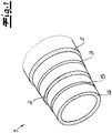
- the figures show a multilayer motor vehicle pipeline (1) according to the invention, the exemplary embodiment being a fuel pipeline for the passage of fuels.
- the pipeline 1 has an outer layer 2, which in the exemplary embodiment consists of polyamide 12 or essentially of polyamide 12.
- This outer layer 2 may have a layer thickness between 0.2 and 0.4 mm.
- a first adhesion promoter layer 3 adjoins the outer layer 2 on the inside, which is preferred and in the exemplary embodiment is an adhesion promoter layer 3 based on a modified polyamide 6.12.
- the layer thickness of the first adhesion promoter layer 3 may be 0.03 to 0.1 mm in the exemplary embodiment.
- the inside of the first adhesion promoter layer 3 is immediately followed by a barrier layer 4, which in the exemplary embodiment consists or essentially consists of EVOH.
- the thickness of the barrier layer 4 is advantageously 0.1 to 0.3 mm.
- a second adhesion promoter layer 5 immediately adjoins the inside of the barrier layer 4, which is preferred and in the exemplary embodiment is an adhesion promoter layer 5 based on polyamide 6.12.
- the layer thickness of the second adhesion promoter layer 5 is preferably 0.03 to 0.1 mm.
- the inner layer 6 directly adjoins the second adhesion promoter layer 5 on the inside, which according to one embodiment variant and in the exemplary embodiment consists or essentially consists of a thermoplastic polyurethane (TPU).
- TPU thermoplastic polyurethane
- the layer thickness of the inner layer 6 may be 0.1 to 0.4 mm in the exemplary embodiment. It is within the scope of the invention that the inner layer 6 can be provided with conductivity additives. -
- the total layer thickness of the pipeline is expediently 0.7 to 3 mm, preferably 0.7 to 2.5 mm.
Description
- Die Erfindung betrifft eine mehrschichtige Kraftfahrzeug-Rohrleitung zur Durchleitung eines fluiden Mediums, insbesondere zur Durchleitung von Kraftstoffen, wobei die Rohrleitung zumindest fünf Schichten aufweist. Die erfindungsgemäße mehrschichtige Kraftfahrzeug-Rohrleitung wird insbesondere als Kraftstoff-Rohrleitung in Fahrzeugen bzw. Kraftfahrzeugen eingesetzt. Grundsätzlich kann die Kraftfahrzeug-Rohrleitung auch als Entlüftungsleitung in Tankentlüftungssystemen eingesetzt werden. Bei dieser Verwendung wird die Rohrleitung insbesondere mit Kraftstoffdämpfen und ihren Kondensaten beaufschlagt. Prinzipiell kann die erfindungsgemäße Kraftfahrzeug-Rohrleitung auch für andere Zwecke verwendet werden, beispielsweise als Leitung für Kühl- und Temperiermedien.
- Mehrschichtige Kraftfahrzeug-Rohrleitungen der eingangs genannten Art sind aus der Praxis in verschiedenen Ausführungsformen bekannt. Viele dieser bekannten Rohrleitungen weisen den Nachteil auf, dass sie beim Durchleiten von Kraftstoffen unerwünschten Auswaschungen von Rohrleitungskomponenten ausgesetzt sind. Das betrifft vor allem die in Kontakt mit dem Kraftstoff stehende Innenschicht, aber auch die angrenzenden mittleren Schichten. Bei vielen bekannten Kraftfahrzeug-Rohrleitungen werden aus den Schichten Oligomere und dergleichen Stoffbestandteile von dem Kraftstoff ausgewaschen und diese Substanzen schlagen sich dann in nachteilhafter Weise im Kraftstoffsystem nieder. Daraus können Probleme -beispielsweise an Düsen und ähnlichen Komponenten - resultieren. Aus diesen Gründen lassen viele bekannte Rohrleitungen im Hinblick auf ihre Resistenz gegenüber den Kraftstoffen zu wünschen übrig. Als Folge genügen auch die Barriereeigenschaften dieser Rohrleitungen oftmals nicht den Anforderungen. In der Vergangenheit wurde versucht, dieses Problem durch unterschiedliche Variierung der Schichten - insbesondere der Innenschichten - zu lösen. Dabei haben Verbesserungen in Bezug auf unerwünschte Auswaschungen aber zu anderen Nachteilen geführt, nämlich zu einer verringerten mechanischen Widerstandsfähigkeit und/oder einer verringerten thermischen Resistenz und/oder einer verringerten Resistenz gegenüber äußeren korrosiven Einflüssen. Verschiedene Rohrleitungen, die zur Lösung des genannten Problems eingesetzt wurden, sind aufgrund ihrer Materialauswahl auch verhältnismäßig kostspielig. Insoweit besteht Verbesserungsbedarf.
- Aus
EP 2 772 354 A1 ist eine mehrschichtige Kraftfahrzeug-Rohrleitung mit zumindest fünf Schichten bekannt. Es soll eine Rohrleitung angegeben werden, die ausreichend resistent gegenüber chemischen Beanspruchungen durch in den Kraftstoffen enthaltene Komponenten ist und die sich insbesondere durch eine geringere Permeabilität für in den Kraftstoff enthaltene Alkohole auszeichnet. Sowohl für die Außenschicht als auch für die Innenschicht dieser Rohrleitung wird eine Mehrzahl von Materialmöglichkeiten angegeben. Die Rohrleitung weist zwingend eine erste Trägerschicht aus Polyamid sowie eine zweite Trägerschicht aus Polyamid auf. Diese Rohrleitungen haben sich grundsätzlich bewährt. - In
DE 10 2013 114 630 A1 wird ein Auskleidungselement zur Sanierung einer Rohrleitung beschrieben. Dabei geht es um Rohrleitungen im Bereich der Kanalisation und im Bereich von Gebäuden. Es geht hier darum, ein Auskleidungselement bereitzustellen, das beim Inversieren, Andrücken und/oder Aushärten eine verbesserte Maßbeständigkeit in Rohrlängsrichtung aufweist.US 2009/269532 A1 offenbart eine mehrschichtige Kraftfahrzeug-Rohrleitung. - Schließlich ist aus
WO 2017/089113 A1 eine Tank-Innenrohrleitung bekannt, die in Kraftstofftanks von Kraftfahrzeugen eingesetzt wird. Die Rohrleitung weist eine Rohrwandung aus zumindest drei Schichten auf, wobei eine Außenschicht auf Basis eines aromatischen Polyamids, eine Zwischenschicht auf Basis von Polyamid und eine Innenschicht auf Basis eines aromatischen Polyamids vorgesehen ist. Zwischengeschaltete Haftvermittlerschichten sind möglich.
Der Erfindung liegt das technische Problem zugrunde, eine mehrschichtige Kraftfahrzeug-Rohrleitung der eingangs genannten Art anzugeben, bei der die eingangs beschriebenen Nachteile effektiv vermieden werden können und die vor allem eine hohe Resistenz gegenüber Auswaschungen und zusätzlich eine ausreichende mechanische Widerstandsfähigkeit sowie eine optimale thermische Resistenz aufweist. Außerdem soll die mehrschichtige Kraftfahrzeug-Rohrleitung auch gegenüber äußeren korrosiven Einflüssen bzw. gegenüber korrosiven Medien - beispielsweise gegenüber Metallchloriden - ausreichend resistent sein. - Zur Lösung des technischen Problems lehrt die Erfindung eine mehrschichtige Kraftfahrzeug-Rohrleitung zur Durchleitung eines fluiden Mediums, insbesondere zur Durchleitung von Kraftstoffen, wobei die Rohrleitung zumindest fünf Schichten aufweist und zwar mit folgendem Schichtaufbau von außen nach innen:
- eine Außenschicht aus zumindest einem Polyamid,
- eine erste Haftvermittlerschicht,
- eine Sperrschicht mit Barriereeigenschaften gegenüber zumindest einer Komponente des fluiden Mediums,
- eine zweite Haftvermittlerschicht,
- eine Innenschicht aus zumindest einem thermoplastischen Polyurethan (TPU) und/oder aus zumindest einem teilaromatischen Polyamid (PPA),
- Es liegt im Rahmen der Erfindung, dass eine Außenschicht aus zumindest einem Polyamid vorgesehen ist. Außenschicht aus zumindest einem Polyamid meint im Rahmen der Erfindung, dass die Außenschicht aus zumindest einem Polyamid besteht bzw. im Wesentlichen aus zumindest einem Polyamid besteht. Eine besonders bevorzugte Ausführungsform der Erfindung ist dadurch gekennezeichnet, dass die Außenschicht aus Polyamid 12 und/oder aus Polyamid 6.12 bzw. im Wesentlichen aus Polyamid 12 und/oder aus Polyamid 6.12 besteht. Es empfiehlt sich, dass die Dicke der Außenschicht 5 bis 50 %, vorzugsweise 5 bis 45 % und insbesondere 7 bis 40 % der Gesamtschichtdicke der Rohrleitung beträgt. Empfohlenermaßen beläuft sich die maximale Dicke der Außenschicht auf 0,4 mm. Zweckmäßigerweise liegt die Dicke der Außenschicht zwischen 0,1 und 0,4 mm, bevorzugt zwischen 0,2 und 0,4 mm.
- Erfindungsgemäß ist zwischen der Außenschicht und der Sperrschicht zumindest eine erste Haftvermittlerschicht vorgesehen. Gemäß einer bewährten Ausführungsform ist zwischen Außenschicht und Sperrschicht lediglich die erste Haftvermittlerschicht angeordnet und dabei ist die erste Haftvermittlerschicht unmittelbar mit der Außenschicht einerseits und unmittelbar mit der Sperrschicht andererseits verbunden. Zweckmäßigerweise wird eine Haftvermittlerschicht auf Basis zumindest eines Polyamids und/oder auf Basis zumindest eines Polyolefins verwendet. Falls eine Haftvermittlerschicht auf Basis von Polyamid eingesetzt wird, handelt es sich empfohlenermaßen um ein modifiziertes Polyamid und zwar bevorzugt um ein modifiziertes Polyamid auf Basis von Polyamid 6.12. Bei dem Einsatz einer ersten Haftvermittlerschicht auf Basis eines Polyolefins wird empfohlenermaßen eine Haftvermittlerschicht auf Basis von Polypropylen eingesetzt. Bei dem Polypropylen handelt es sich zweckmäßigerweise um ein modifiziertes Polypropylen, das beispielsweise mit einem Carbonsäurederivat modifiziert ist. - Es liegt im Rahmen der Erfindung, dass die Dicke der ersten Haftvermittlerschicht 3 bis 30 %, vorzugsweise 5 bis 20 % und bevorzugt 5 bis 15 % der Gesamtschichtdicke der Rohrleitung beträgt. Die Dicke der ersten Haftvermittlerschicht beträgt zweckmäßigerweise 0,03 bis 0,15 mm und insbesondere 0,03 bis 0,1 mm.
- Erfindungsgemäß ist die Sperrschicht eine Sperrschicht auf Basis zumindest einer Komponente aus der Gruppe "EVOH, Fluorpolymer" ist. EVOH meint dabei Ethylen-Vinylalkohol-Copolymer. Nach einer ersten Ausführungsform besteht die Sperrschicht aus EVOH bzw. im Wesentlichen aus EVOH. Gemäß einer zweiten Ausführungsform besteht die Sperrschicht aus zumindest einem Fluorpolymer bzw. im Wesentlichen aus zumindest einem Fluorpolymer. Besonders bevorzugt besteht dabei die Sperrschicht aus lediglich einem Fluorpolymer bzw. im Wesentlichen aus lediglich einem Fluorpolymer. Vorzugsweise beträgt die Dicke der Sperrschicht 5 bis 50 %, bevorzugt 10 bis 40 % und insbesondere 10 bis 35 % der Gesamtschichtdicke der erfindungsgemäßen Rohrleitung. Es liegt im Rahmen der Erfindung, dass die Sperrschicht Barriereeigenschaften gegenüber zumindest einer Komponente eines durch die Rohrleitung geleiteten Kraftstoffes aufweist.
- Erfindungsgemäß ist zwischen der Sperrschicht und der Innenschicht der erfindungsgemäßen Rohrleitung zumindest eine zweite Haftvermittlerschicht und nach einer Ausführungsform lediglich eine zweite Haftvermittlerschicht angeordnet. Zweckmäßigerweise ist die zweite Haftvermittlerschicht eine Haftvermittlerschicht auf Basis zumindest eines Polyamids und/oder auf Basis zumindest eines Polyolefins. Wenn eine zweite Haftvermittlerschicht auf Basis zumindest eines Polyamids verwendet wird, handelt es sich empfohlenermaßen um eine Haftvermittlerschicht auf Basis von Polyamid 6.12. Zweckmäßigerweise wird für die zweite Haftvermittlerschicht ein modifiziertes Polyamid und insbesondere ein modifiziertes Polyamid auf Basis von Polyamid 6.12 verwendet. Falls es sich um eine Haftvermittlerschicht auf Basis zumindest eines Polyolefins handelt, wird vorzugsweise eine Haftvermittlerschicht auf Basis von Polypropylen eingesetzt und insbesondere auf Basis eines modifizierten Polypropylens. Das Polypropylen wird dabei beispielsweise mit einem Carbonsäurederivat modifiziert. Die Dicke der zweiten Haftvermittlerschicht beträgt 3 bis 20 %, vorzugsweise 5 bis 20 % und insbesondere 5 bis 15 % der Gesamtschichtdicke der Rohrleitung. Die Dicke der zweiten Haftvermittlerschicht beträgt vorzugsweise 0,03 bis 0,15 mm und insbesondere 0,03 bis 0,1 mm.
- Es liegt im Rahmen der Erfindung, dass eine Innenschicht aus zumindest einem thermoplastischen Polyurethan (TPU) und/oder aus zumindest einem teilaromatischen Polyamid (PPA) eingesetzt wird. Es liegt dabei weiterhin im Rahmen der Erfindung, dass die Innenschicht aus zumindest einem thermoplastischen Polyurethan (TPU) besteht oder im Wesentlichen aus zumindest einem thermoplastischen Polyurethan (TPU) besteht und/oder aus zumindest einem teilaromatischen Polyamid (PPA) besteht bzw. im Wesentlichen aus zumindest einem teilaromatischen Polyamid (PPA) besteht. Nach einer Ausführungsform besteht die Innenschicht lediglich aus einem thermoplastischen Polyurethan (TPU) bzw. im Wesentlichen aus lediglich einem thermoplastischen Polyurethan (TPU). - Zweckmäßigerweise beträgt die Dicke der Innenschicht 5 bis 50 %, vorzugsweise 5 bis 45 % und bevorzugt 7 bis 40 % der Gesamtschichtdicke der Rohrleitung. Empfohlenermaßen beträgt die Dicke der Innenschicht 0,05 bis 0,45 mm, vorzugsweise 0,05 bis 0,4 mm und insbesondere 0,1 bis 0,35 mm. Gemäß einer Ausführungsform der Erfindung ist die Innenschicht der Rohrleitung mit Leitfähigkeitszusätzen versehen. Es liegt im Rahmen der Erfindung, dass die Innenschicht die innerste Schicht der Rohrleitung ist und somit mit dem durch die Rohrleitung strömenden Medium bzw. mit dem durch die Rohrleitung strömenden Kraftstoff in Kontakt steht.
- Eine zweckmäßige Ausführungsform der Erfindung ist dadurch gekennzeichnet, dass die Dicke der ersten Haftvermittlerschicht und/oder die Dicke der zweiten Haftvermittlerschicht geringer ist als die Dicke der Außenschicht. Die Dicke der ersten Haftvermittlerschicht und die Dicke der zweiten Haftvermittlerschicht sind geringer ist als die Dicke der Sperrschicht. Vorzugsweise ist die Dicke der ersten Haftvermittlerschicht und/oder die Dicke der zweiten Haftvermittlerschicht geringer als die Dicke der Innenschicht.
- Gemäß einer bewährten Ausführungsform der Erfindung ist die Dicke der Außenschicht größer als die Dicke der Sperrschicht und/oder größer als die Dicke der Innenschicht. - Eine Ausführungsform der Erfindung ist dadurch gekennzeichnet, dass die erfindungsgemäße Rohrleitung lediglich aus den fünf beschriebenen Schichten (Außenschicht, erste Haftvermittlerschicht, Sperrschicht, zweite Haftvermittlerschicht, Innenschicht) besteht. Grundsätzlich können aber auch weitere Schichten vorgesehen sein. So kann beispielsweise eine weitere Haftvermittlerschicht eingesetzt werden und/oder eine weitere Sperrschicht. Prinzipiell kann auf der Außenschicht auch noch zumindest eine zusätzliche Deckschicht angeordnet sein und/oder die Außenschicht wird von einem Hüllrohr umgeben.
- Empfohlenermaßen wird die erfindungsgemäße Kraftfahrzeug-Rohrleitung - vorzugsweise Kraftstoff-Rohrleitung - durch Extrusion bzw. Koextrusion der Schichten hergestellt. Die erfindungsgemäßen Schichtkomponenten machen eine einfache und wenig aufwendige Koextrusion möglich. Die Koextrusion der Schichten der erfindungsgemäßen Rohrleitung ist vor allem bei moderaten Temperaturen realisierbar.- Bezüglich der geometrischen Gestaltung der erfindungsgemäßen Rohrleitung sind verschiedene Varianten möglich. So ist die erfindungsgemäße Rohrleitung als glattes unprofiliertes Rohr herstellbar oder auch als Wellrohr erzeugbar.
- Nachfolgend wird die Erfindung anhand von Ausführungsbeispielen näher erläutert:
Gemäß einem ersten Ausführungsbeispiel besteht die Außenschicht der erfindungsgemäßen Rohrleitung aus Polyamid 12 bzw. im Wesentlichen aus Polyamid 12. Zweckmäßigerweise hat die Außenschicht eine Dicke von 0,15 bis 0,35 mm. - Es liegt im Rahmen der Erfindung, dass innenseitig an die Außenschicht eine erste Haftvermittlerschicht anschließt, die bevorzugt aus einem modifizierten Polyamid, insbesondere aus einem modifizierten Polyamid 6.12 besteht bzw. im Wesentlichen besteht. Zweckmäßigerweise hat diese erste Haftvermitterschicht eine Dicke von 0,03 bis 0,1 mm. - Weiterhin liegt es im Rahmen der Erfindung, dass an diese erste Haftvermittlerschicht innenseitig eine Sperrschicht anschließt, die nach einer bevorzugten Ausführungsvariante aus EVOH besteht bzw. im Wesentlichen besteht. Die Sperrschicht weist zweckmäßigerweise eine Schichtdicke von 0,2 bis 0,7 mm auf. - Empfohlenermaßen schließt innenseitig an die Sperrschicht, vorzugsweise unmittelbar an die Sperrschicht eine zweite Haftvermittlerschicht an, bei der es sich bevorzugt und im Ausführungsbeispiel um eine zweite Haftvermittlerschicht auf Basis von Polypropylen handelt. Zweckmäßigerweise handelt es sich um ein modifziertes Polypropylen und insbesondere um ein mit einem Carbonsäurederivat modifizierten Polypropylen. Die zweite Haftvermittlerschicht hat bevorzugt eine Dicke von 0,03 bis 0,1 mm. - Nach bewährter Ausführungsform der Erfindung schließt innenseitig an die zweite Haftvermittlerschicht bzw. unmittelbar innenseitig an die zweite Haftvermittlerschicht eine Innenschicht an, wobei die Innenschicht bevorzugt und in diesem Ausführungsbeispiel aus zumindest einem thermoplastischen Polyurethan (TPU) besteht bzw. im Wesentlichen besteht. Zweckmäßigerweise beträgt die Schichtdicke der Innenschicht 0,05 bis 0,4 mm. - Es empfiehlt sich, dass die Gesamtschichtdicke der Rohrleitung 0,7 bis 2,5 mm beträgt. - Gemäß einem zweiten Ausführungsbeispiel der Erfindung besteht die Außenschicht aus Polyamid 6.12 bzw. im Wesentlichen aus Polyamid 6.12 Es empfiehlt sich, dass die Außenschicht eine Dicke von 0,15 bis 0,35 mm aufweist. - Zweckmäßigerweise schließt innenseitig an die Außenschicht unmitttelbar eine erste Haftvermittlerschicht an, die bevorzugt und im Ausführungsbeispiel eine erste Haftvermittlerschicht auf Basis eines Polyamids und insbesondere auf Basis von Polyamid 6.12 ist. Es handelt sich dabei vorzugsweise um ein modifiziertes Polyamid bzw. ein modifiziertes Polyamid 6.12. Es empfiehlt sich, dass die erste Haftvermittlerschicht eine Dicke von 0,03 bis 0,1 mm aufweist. - Bevorzugt und im zweiten Ausführungsbeispiel schließt innenseitig an die erste Haftvermittlerschicht unmittelbar die Sperrschicht an, die empfohlenermaßen und im zweiten Ausführungsbeispiel aus einem Fluorpolymer bzw. im Wesentlichen aus einem Fluorpolymer besteht. Zweckmäßigerweise weist die Sperrschicht eine Schichtdicke von 0,05 bis 0,3 mm auf. - Empfohlenermaßen schließt an die Sperrschicht innenseitig und zwar bevorzugt unmittelbar innenseitig die zweite Haftvermittlerschicht an, die im zweiten Ausführungsbeispiel auf Basis zumindest eines Polyamids und zwar bevorzugt auf Basis von Polyamid 6.12 ausgebildet ist. Es hat sich bewährt, dass die zweite Haftvermittlerschicht eine Schichtdicke von 0,03 bis 0,1 mm aufweist. - Zweckmäßigerweise schließt innenseitig an die zweite Haftvermittlerschicht und zwar bevorzugt unmittelbar innenseitig an die zweite Haftvermittlerschicht eine Innenschicht an, die vorzugsweise und im zweiten Ausführungsbeispiel aus zumindest einem teilaromatischen Polyamid (PPA) besteht bzw. im Wesentlichen besteht. Bevorzugt besteht die Innenschicht lediglich aus einem teilaromatischen Polyamid (PPA) bzw. im Wesentlichen aus lediglich einem teilaromatischen Polyamid (PPA). Es liegt im Rahmen der Erfindung, dass die Schichtdicke der Innenschicht 0,05 bis 0,4 mm beträgt.-Zweckmäßigerweise liegt die Gesamtschichtdicke der Rohrleitung bei dem zweiten Ausführungsbeispiel ebenfalls im Bereich zwischen 0,7 und 2,5 mm.
- Der Erfindung liegt die Erkenntnis zugrunde, dass die erfindungsgemäße Kraftfahrzeug-Rohrleitung eine überraschend hohe Resistenz gegenüber Auswaschungen von Schichtkomponenten aufweist. Das gilt insbesondere für die Innenschicht der erfindungsgemäßen Rohrleitung, jedoch auch für die daran angrenzenden Rohrschichten. Problemlos kann bei der erfindungsgemäßen Rohrleitung ein Auswaschungsgrad von kleiner 6 g/m2 eingehalten werden und überraschenderweise ist der erfindungsgemäß erzielte Auswaschungsgrad deutlich kleiner als der genannte Wert. Die Einhaltung des vorgenannten Wertes für den Auswaschungsgrad wird von manchen Automobilherstellern gefordert. Hervorzuheben ist auch, dass die erfindungsgemäße Kraftfahrzeug-Rohrleitung problemlos für verschiedene Kraftstoffsorten eingesetzt werden kann und im Wesentlichen bei all diesen Kraftstoffsorten die gleichen positiven Resultate zeigt. Im Gegensatz zu vielen aus dem Stand der Technik bekannten Rohrleitungen weist die erfindungsgemäße Rohrleitung zusätzlich zu der hervorragenden Auswaschungsbeständigkeit auch eine optimale mechanische Widerstandsfähigkeit auf wie auch eine vorteilhafte Resistenz gegenüber hohen und tiefen Temperaturen. Die erfindungsgemäße Rohrleitung ist problemlos beständig im Temperaturbereich zwischen - 40°C und + 140°C. Zu betonen ist weiterhin, dass im Hinblick auf diese erheblichen Vorteile die erfindungsgemäße Rohrleitung nichtsdestoweniger aus relativ kostengünstigen Materialien herstellbar ist. Ein weiterer hervorzuhebender Vorteil besteht darin, dass die erfindungsgemäße Rohrleitung einfach koextrudiert werden kann und vor allem bei moderaten Temperaturen koextrudiert werden kann. Die gesamte erfindungsgemäße Rohrleitung ist gegenüber äußeren chemischen Einflüssen bzw. korrosiven Einflüssen -beispielsweise aufgrund von Metallchloriden und dergleichen - außergewöhnlich resistent. Insoweit vereint die erfindungsgemäße Kraftfahrzeug-Rohrleitung eine Mehrzahl von Vorteilen.
- Nachfolgend wird die Erfindung anhand einer lediglich ein Ausführungsbeispiel darstellenden Zeichnung näher erläutert. Es zeigen in schematischer Darstellung:
- Fig. 1
- eine perspektivische Ansicht einer erfindungsgemäßen Rohrleitung und
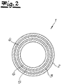
- Fig. 2
- einen Schnitt durch den Gegenstand nach
Fig. 1 . - Die Figuren zeigen eine erfindungsgemäße mehrschichtige Kraftfahrzeug-Rohrleitung (1), wobei es sich im Ausführungsbeispiel um eine Kraftstoff-Rohrleitung zur Durchleitung von Kraftstoffen handelt. Die Rohrleitung 1 weist eine Außenschicht 2 auf, die im Ausführungsbeispiel aus Polyamid 12 bzw. im Wesentlichen aus Polyamid 12 besteht. Diese Außenschicht 2 mag eine Schichtdicke zwischen 0,2 und 0,4 mm aufweisen. Zweckmäßigerweise und im Ausführungsbeispiel schließt innenseitig an die Außenschicht 2 eine erste Haftvermittlerschicht 3 an, die bevorzugt und im Ausführungsbeispiel eine Haftvermittlerschicht 3 auf Basis eines modifizierten Polyamids 6.12 ist. Die Schichtdicke der ersten Haftvermittlerschicht 3 mag im Ausführungsbeispiel 0,03 bis 0,1 mm betragen.
- Es liegt im Rahmen der Erfindung, dass an die erste Haftvermittlerschicht 3 innenseitig unmittelbar eine Sperrschicht 4 anschließt, die im Ausführungsbeispiel aus EVOH besteht bzw. im Wesentlichen besteht. Die Dicke der Sperrschicht 4 beträgt zweckmäßigerweise 0,1 bis 0,3 mm. Bewährtermaßen und im Ausführungsbeispiel schließt an die Sperrschicht 4 innenseitig unmittelbar eine zweite Haftvermittlerschicht 5 an, die bevorzugt und im Ausführungsbeispiel eine Haftvermittlerschicht 5 auf Basis von Polyamid 6.12 ist. Empfohlenermaßen beträgt die Schichtdicke der zweiten Haftvermittlerschicht 5 0,03 bis 0,1 mm.
- Gemäß bevorzugter Ausführungsform und im Ausführungsbeispiel nach den Figuren schließt an die zweite Haftvermittlerschicht 5 innenseitig unmittelbar die Innenschicht 6 an, die gemäß einer Ausführungsvariante und im Ausführungsbeispiel aus einem thermoplastischen Polyurethan (TPU) besteht bzw. im Wesentlichen besteht. Die Schichtdicke der Innenschicht 6 mag im Ausführungsbeispiel 0,1 bis 0,4 mm betragen. Es liegt im Rahmen der Erfindung, dass die Innenschicht 6 mit Leitfähigkeitszusätzen versehen werden kann. - Zweckmäßigerweise beträgt die Gesamtschichtdicke der Rohrleitung 0,7 bis 3 mm, vorzugsweise 0,7 bis 2,5 mm.
wobei die Dicke der ersten Haftvermittlerschicht und die Dicke der zweiten Haftvermittlerschicht geringer ist als die Dicke der Sperrschicht wobei die Dicke der zweiten Haftvermittlerschicht 3 bis 20% der Gesamtdicke beträgt,
und wobei die Sperrschicht eine Sperrschicht auf Basis zumindest einer Komponente aus der Gruppe "EVOH, Fluorpolymer" ist.
Claims (12)
- Mehrschichtige Kraftfahrzeug-Rohrleitung (1) zur Durchleitung zumindest eines fluiden Mediums, insbesondere zur Durchleitung von Kraftstoffen, wobei die Rohrleitung (1) zumindest fünf Schichten aufweist und zwar mit folgendem Schichtaufbau von außen nach innen:- eine Außenschicht (2) aus zumindest einem Polyamid bzw. im Wesentlichen aus zumindest einem Polyamid,- eine erste Haftvermittlerschicht (3),- eine Sperrschicht (4) mit Barriereeigenschaften gegenüber zumindest einer Komponente des fluiden Mediums,- eine zweite Haftvermittlerschicht (5),- eine Innenschicht (6) aus zumindest einem thermoplastischen Polyurethan (TPU) und/oder zumindest einem teilaromatischen Polyamid (PPA) bzw. im Wesentlichen aus zumindest einem TPU und/oder PPA,wobei die Gesamtschichtdicke der Rohrleitung (1) 0,7 bis 3 mm, vorzugsweise 0,7 bis 2,5 mm und bevorzugt 0,8 bis 2 mm beträgt,
wobei die Dicke der ersten Haftvermittlerschicht (3) und die Dicke der zweiten Haftvermittlerschicht (5) geringer ist als die Dicke der Sperrschicht (4)
wobei die Dicke der zweiten Haftvermittlerschicht (5) 3 bis 20 % der Gesamtschichtdicke beträgt
und wobei die Sperrschicht (4) eine Sperrschicht (4) auf Basis zumindest einer Komponente aus der Gruppe "EVOH, Fluorpolymer" ist. - Mehrschichtige Kraftfahrzeug-Rohrleitung nach Anspruch 1, wobei die Außenschicht (2) aus Polyamid 12 und/oder aus Polyamid 6.12 bzw. im Wesentlichen aus Polyamid 12 und/oder aus Polyamid 6.12 besteht.
- Mehrschichtige Kraftfahrzeug-Rohrleitung nach einem der Ansprüche 1 oder 2, wobei die Dicke der Außenschicht (2) 5 bis 50 %, insbesondere 5 bis 45 % und bevorzugt 7 bis 40 % der Gesamtschichtdicke der Rohrleitung (1) beträgt.
- Mehrschichtige Kraftfahrzeug-Rohrleitung nach einem der Ansprüche 1 bis 3, wobei die erste Haftvermittlerschicht (3) eine Haftvermittlerschicht (3) auf Basis zumindest eines Polyamids und/oder auf Basis zumindest eines Polyolefins ist.
- Mehrschichtige Kraftfahrzeug-Rohrleitung nach einem der Ansprüche 1 bis 4, wobei die erste Haftvermittlerschicht (3) eine Haftvermittlerschicht (3) auf Basis von Polyamid 6.12 und/oder auf Basis von Polypropylen ist.
- Mehrschichtige Kraftfahrzeug-Rohrleitung nach einem der Ansprüche 1 bis 5, wobei die Dicke der ersten Haftvermittlerschicht (3) 3 bis 30 %, bevorzugt 5 bis 20 % der Gesamtschichtdicke der Rohrleitung (1) beträgt.
- Mehrschichtige Kraftfahrzeug-Rohrleitung nach einem der Ansprüche 1 bis 6, wobei die Dicke der Sperrschicht (4) 5 bis 50 %, bevorzugt 10 bis 40 % und insbesondere 10 bis 35 % der Gesamtschichtdicke der Rohrleitung (1) beträgt.
- Mehrschichtige Kraftfahrzeug-Rohrleitung nach einem der Ansprüche 1 bis 7, wobei die zweite Haftvermittlerschicht (5) eine Haftvermittlerschicht (5) auf Basis zumindest eines Polyamids und/oder auf Basis zumindest eines Polyolefins ist.
- Mehrschichtige Kraftfahrzeug-Rohrleitung nach einem der Ansprüche 1 bis 8, wobei die zweite Haftvermittlerschicht (5) eine Haftvermittlerschicht (5) auf Basis von Polyamid 6.12 und/oder auf Basis von Polypropylen ist.
- Mehrschichtige Kraftfahrzeug-Rohrleitung nach einem der Ansprüche 1 bis 9, wobei die Dicke der Innenschicht (6) 5 bis 50 %, vorzugsweise 5 bis 45 % und bevorzugt 7 bis 40 % der Gesamtschichtdicke der Rohrleitung (1) beträgt.
- Mehrschichtige Kraftfahrzeug-Rohrleitung nach einem der Ansprüche 1 bis 10, wobei die Innenschicht (6) mit Leitfähigkeitszusätzen versehen ist.
- Mehrschichtige Kraftfahrzeug-Rohrleitung nach einem der Ansprüche 1 bis 11, wobei die Rohrleitung (1) durch Koextrusion hergestellt ist.
Priority Applications (4)
| Application Number | Priority Date | Filing Date | Title |
|---|---|---|---|
| KR1020207027276A KR20210004962A (ko) | 2018-02-22 | 2019-02-21 | 다층 자동차 호스 라인 |
| PCT/IB2019/051434 WO2019162884A1 (en) | 2018-02-22 | 2019-02-21 | Multiple layer motor vehicle hose line |
| CN201980014881.3A CN112203841A (zh) | 2018-02-22 | 2019-02-21 | 多层机动车辆软管线 |
| US16/975,051 US20200400253A1 (en) | 2018-02-22 | 2019-02-21 | Multiple layer motor vehicle hose line |
Applications Claiming Priority (1)
| Application Number | Priority Date | Filing Date | Title |
|---|---|---|---|
| EP18158180.2A EP3530454B1 (de) | 2018-02-22 | 2018-02-22 | Mehrschichtige kraftfahrzeug-rohrleitung |
Publications (2)
| Publication Number | Publication Date |
|---|---|
| EP3530450A1 EP3530450A1 (de) | 2019-08-28 |
| EP3530450B1 true EP3530450B1 (de) | 2020-07-29 |
Family
ID=61274097
Family Applications (2)
| Application Number | Title | Priority Date | Filing Date |
|---|---|---|---|
| EP18158180.2A Active EP3530454B1 (de) | 2018-02-22 | 2018-02-22 | Mehrschichtige kraftfahrzeug-rohrleitung |
| EP18171614.3A Active EP3530450B1 (de) | 2018-02-22 | 2018-05-09 | Mehrschichtige kraftfahrzeug-rohrleitung |
Family Applications Before (1)
| Application Number | Title | Priority Date | Filing Date |
|---|---|---|---|
| EP18158180.2A Active EP3530454B1 (de) | 2018-02-22 | 2018-02-22 | Mehrschichtige kraftfahrzeug-rohrleitung |
Country Status (5)
| Country | Link |
|---|---|
| US (2) | US20210086485A1 (de) |
| EP (2) | EP3530454B1 (de) |
| KR (2) | KR20210004962A (de) |
| CN (2) | CN112166033A (de) |
| WO (2) | WO2019162886A1 (de) |
Families Citing this family (1)
| Publication number | Priority date | Publication date | Assignee | Title |
|---|---|---|---|---|
| EP3875263A1 (de) | 2020-03-06 | 2021-09-08 | TI Automotive (Fuldabrück) GmbH | Mehrschichtige kraftfahrzeug-rohrleitung |
Citations (2)
| Publication number | Priority date | Publication date | Assignee | Title |
|---|---|---|---|---|
| US20090269532A1 (en) * | 2008-03-03 | 2009-10-29 | Arkema France | Multilayer structure comprising at least one stabilized layer |
| WO2017089113A1 (de) * | 2015-11-23 | 2017-06-01 | TI Automotive (Fuldabrück) GmbH | Tank-innenrohrleitung und tank mit zumindest einer tank-innenrohrleitung |
Family Cites Families (11)
| Publication number | Priority date | Publication date | Assignee | Title |
|---|---|---|---|---|
| EP0637509B1 (de) * | 1993-08-03 | 2002-10-23 | Nitta Moore Company | Kraftstofftransportschlauch |
| US6555243B2 (en) * | 2000-06-09 | 2003-04-29 | Ems-Chemie Ag | Thermoplastic multilayer composites |
| EP1182345B1 (de) * | 2000-08-02 | 2007-01-03 | TI Automotive (Fuldabrück) GmbH | Kraftfahrzeugrohrleitung |
| DE50207999D1 (de) * | 2002-05-07 | 2006-10-12 | Ems Chemie Ag | Gewellter Mehrschicht-Polymer-Schlauch- oder Rohrleitung mit reduzierter Längenänderung |
| FR2911380B1 (fr) * | 2007-01-17 | 2009-10-02 | Coutier Moulage Gen Ind | Canalisation pour le transport de fluide. |
| US7866348B2 (en) * | 2008-05-01 | 2011-01-11 | Saint-Gobain Performance Plastics Corporation | Multi-layered fuel tubing |
| DE102011089616A1 (de) * | 2011-12-22 | 2013-06-27 | Fränkische Industrial Pipes GmbH & Co. KG | Mehrlagige Kraftstoffleitung |
| EP2772354B1 (de) * | 2013-03-01 | 2018-12-05 | TI Automotive (Fuldabrück) GmbH | Mehrschichtige Kraftstoffrohrleitung |
| DE102013114630A1 (de) * | 2013-12-20 | 2015-06-25 | Trelleborg Pipe Seals Duisburg Gmbh | Auskleidungselement zur Sanierung einer Rohrleitung |
| EP3069865B1 (de) * | 2015-03-17 | 2021-10-13 | TI Automotive (Fuldabrück) GmbH | Mehrschichtige kraftfahrzeugrohrleitung |
| CN105299333A (zh) * | 2015-11-30 | 2016-02-03 | 河北亚大汽车塑料制品有限公司 | 一种多层管 |
-
2018
- 2018-02-22 EP EP18158180.2A patent/EP3530454B1/de active Active
- 2018-05-09 EP EP18171614.3A patent/EP3530450B1/de active Active
-
2019
- 2019-02-21 WO PCT/IB2019/051436 patent/WO2019162886A1/en active Application Filing
- 2019-02-21 CN CN201980011929.5A patent/CN112166033A/zh active Pending
- 2019-02-21 US US16/975,040 patent/US20210086485A1/en not_active Abandoned
- 2019-02-21 CN CN201980014881.3A patent/CN112203841A/zh active Pending
- 2019-02-21 KR KR1020207027276A patent/KR20210004962A/ko not_active Application Discontinuation
- 2019-02-21 KR KR1020207027320A patent/KR20210005557A/ko not_active Application Discontinuation
- 2019-02-21 WO PCT/IB2019/051434 patent/WO2019162884A1/en active Application Filing
- 2019-02-21 US US16/975,051 patent/US20200400253A1/en not_active Abandoned
Patent Citations (2)
| Publication number | Priority date | Publication date | Assignee | Title |
|---|---|---|---|---|
| US20090269532A1 (en) * | 2008-03-03 | 2009-10-29 | Arkema France | Multilayer structure comprising at least one stabilized layer |
| WO2017089113A1 (de) * | 2015-11-23 | 2017-06-01 | TI Automotive (Fuldabrück) GmbH | Tank-innenrohrleitung und tank mit zumindest einer tank-innenrohrleitung |
Also Published As
| Publication number | Publication date |
|---|---|
| EP3530454B1 (de) | 2020-06-10 |
| EP3530454A1 (de) | 2019-08-28 |
| WO2019162886A1 (en) | 2019-08-29 |
| KR20210005557A (ko) | 2021-01-14 |
| KR20210004962A (ko) | 2021-01-13 |
| CN112166033A (zh) | 2021-01-01 |
| EP3530450A1 (de) | 2019-08-28 |
| US20200400253A1 (en) | 2020-12-24 |
| US20210086485A1 (en) | 2021-03-25 |
| WO2019162884A1 (en) | 2019-08-29 |
| CN112203841A (zh) | 2021-01-08 |
Similar Documents
| Publication | Publication Date | Title |
|---|---|---|
| DE3218539A1 (de) | Doppelwandiges, gewelltes kunststoffrohr | |
| DE2726499A1 (de) | Glasfaserarmiertes kunststoffrohr | |
| EP3613578B1 (de) | Mehrschichtige kraftfahrzeug-temperier-rohrleitung | |
| DE102013109362A1 (de) | Kunststoffschlauch mit Gewebeverstärkung | |
| EP3482987B1 (de) | Verwendung einer rohrleitung als temperier-rohrleitung | |
| EP1754919A1 (de) | Rohr mit doppelter Sperrschicht | |
| EP3530450B1 (de) | Mehrschichtige kraftfahrzeug-rohrleitung | |
| EP1835216B1 (de) | Electrisch leitfähige Kraftfahrzeugrohrleitung aus Kunststoff | |
| DE2708593A1 (de) | Zusammengesetztes rohr aus verschiedenen kunststoffen und verfahren zu dessen herstellung | |
| EP3530453B1 (de) | Mehrschichtige kraftfahrzeug-rohrleitung | |
| EP1740870B1 (de) | Mehrschichtiges rohr | |
| DE102015205081A1 (de) | Mehrlagiges Wellrohr | |
| EP2199073A2 (de) | Kraftfahrzeug-Fluidleitung | |
| DE2820465A1 (de) | Schlauch | |
| DE8104908U1 (de) | Gasdiffusionsfestes rohr | |
| DE3921174C2 (de) | ||
| DE2854570A1 (de) | Verbundschlauch | |
| DE202019101108U1 (de) | Mehrschichtverbundrohr | |
| EP3392033B1 (de) | Tank-innenrohrleitung, insbesondere in kraftstofftanks von kraftfahrzeugen | |
| DE202005002870U1 (de) | Filterrohr für einen Brunnen | |
| DE102007039582A1 (de) | Rohrkupplung | |
| WO2021009095A1 (de) | Fluidleitung mit einem rohr | |
| EP2515017B1 (de) | Schlauch zur Führung von Fluiden | |
| EP3575655B1 (de) | Rohrleitungs-befestigungsaggregat und verfahren zur befestigung einer rohrleitung an einem befestigungsclip | |
| WO2022096977A1 (de) | Mehrschichtige kraftfahrzeug‑rohrleitung |
Legal Events
| Date | Code | Title | Description |
|---|---|---|---|
| STAA | Information on the status of an ep patent application or granted ep patent |
Free format text: STATUS: EXAMINATION IS IN PROGRESS |
|
| PUAI | Public reference made under article 153(3) epc to a published international application that has entered the european phase |
Free format text: ORIGINAL CODE: 0009012 |
|
| 17P | Request for examination filed |
Effective date: 20181109 |
|
| AK | Designated contracting states |
Kind code of ref document: A1 Designated state(s): AL AT BE BG CH CY CZ DE DK EE ES FI FR GB GR HR HU IE IS IT LI LT LU LV MC MK MT NL NO PL PT RO RS SE SI SK SM TR |
|
| AX | Request for extension of the european patent |
Extension state: BA ME |
|
| GRAP | Despatch of communication of intention to grant a patent |
Free format text: ORIGINAL CODE: EPIDOSNIGR1 |
|
| STAA | Information on the status of an ep patent application or granted ep patent |
Free format text: STATUS: GRANT OF PATENT IS INTENDED |
|
| INTG | Intention to grant announced |
Effective date: 20200228 |
|
| GRAS | Grant fee paid |
Free format text: ORIGINAL CODE: EPIDOSNIGR3 |
|
| GRAA | (expected) grant |
Free format text: ORIGINAL CODE: 0009210 |
|
| STAA | Information on the status of an ep patent application or granted ep patent |
Free format text: STATUS: THE PATENT HAS BEEN GRANTED |
|
| AK | Designated contracting states |
Kind code of ref document: B1 Designated state(s): AL AT BE BG CH CY CZ DE DK EE ES FI FR GB GR HR HU IE IS IT LI LT LU LV MC MK MT NL NO PL PT RO RS SE SI SK SM TR |
|
| REG | Reference to a national code |
Ref country code: CH Ref legal event code: EP |
|
| REG | Reference to a national code |
Ref country code: DE Ref legal event code: R096 Ref document number: 502018001986 Country of ref document: DE |
|
| REG | Reference to a national code |
Ref country code: AT Ref legal event code: REF Ref document number: 1295314 Country of ref document: AT Kind code of ref document: T Effective date: 20200815 |
|
| REG | Reference to a national code |
Ref country code: IE Ref legal event code: FG4D Free format text: LANGUAGE OF EP DOCUMENT: GERMAN |
|
| REG | Reference to a national code |
Ref country code: LT Ref legal event code: MG4D |
|
| REG | Reference to a national code |
Ref country code: NL Ref legal event code: MP Effective date: 20200729 |
|
| PG25 | Lapsed in a contracting state [announced via postgrant information from national office to epo] |
Ref country code: FI Free format text: LAPSE BECAUSE OF FAILURE TO SUBMIT A TRANSLATION OF THE DESCRIPTION OR TO PAY THE FEE WITHIN THE PRESCRIBED TIME-LIMIT Effective date: 20200729 Ref country code: GR Free format text: LAPSE BECAUSE OF FAILURE TO SUBMIT A TRANSLATION OF THE DESCRIPTION OR TO PAY THE FEE WITHIN THE PRESCRIBED TIME-LIMIT Effective date: 20201030 Ref country code: LT Free format text: LAPSE BECAUSE OF FAILURE TO SUBMIT A TRANSLATION OF THE DESCRIPTION OR TO PAY THE FEE WITHIN THE PRESCRIBED TIME-LIMIT Effective date: 20200729 Ref country code: BG Free format text: LAPSE BECAUSE OF FAILURE TO SUBMIT A TRANSLATION OF THE DESCRIPTION OR TO PAY THE FEE WITHIN THE PRESCRIBED TIME-LIMIT Effective date: 20201029 Ref country code: ES Free format text: LAPSE BECAUSE OF FAILURE TO SUBMIT A TRANSLATION OF THE DESCRIPTION OR TO PAY THE FEE WITHIN THE PRESCRIBED TIME-LIMIT Effective date: 20200729 Ref country code: NO Free format text: LAPSE BECAUSE OF FAILURE TO SUBMIT A TRANSLATION OF THE DESCRIPTION OR TO PAY THE FEE WITHIN THE PRESCRIBED TIME-LIMIT Effective date: 20201029 Ref country code: HR Free format text: LAPSE BECAUSE OF FAILURE TO SUBMIT A TRANSLATION OF THE DESCRIPTION OR TO PAY THE FEE WITHIN THE PRESCRIBED TIME-LIMIT Effective date: 20200729 Ref country code: SE Free format text: LAPSE BECAUSE OF FAILURE TO SUBMIT A TRANSLATION OF THE DESCRIPTION OR TO PAY THE FEE WITHIN THE PRESCRIBED TIME-LIMIT Effective date: 20200729 Ref country code: PT Free format text: LAPSE BECAUSE OF FAILURE TO SUBMIT A TRANSLATION OF THE DESCRIPTION OR TO PAY THE FEE WITHIN THE PRESCRIBED TIME-LIMIT Effective date: 20201130 |
|
| PG25 | Lapsed in a contracting state [announced via postgrant information from national office to epo] |
Ref country code: PL Free format text: LAPSE BECAUSE OF FAILURE TO SUBMIT A TRANSLATION OF THE DESCRIPTION OR TO PAY THE FEE WITHIN THE PRESCRIBED TIME-LIMIT Effective date: 20200729 Ref country code: LV Free format text: LAPSE BECAUSE OF FAILURE TO SUBMIT A TRANSLATION OF THE DESCRIPTION OR TO PAY THE FEE WITHIN THE PRESCRIBED TIME-LIMIT Effective date: 20200729 Ref country code: RS Free format text: LAPSE BECAUSE OF FAILURE TO SUBMIT A TRANSLATION OF THE DESCRIPTION OR TO PAY THE FEE WITHIN THE PRESCRIBED TIME-LIMIT Effective date: 20200729 Ref country code: IS Free format text: LAPSE BECAUSE OF FAILURE TO SUBMIT A TRANSLATION OF THE DESCRIPTION OR TO PAY THE FEE WITHIN THE PRESCRIBED TIME-LIMIT Effective date: 20201129 |
|
| PG25 | Lapsed in a contracting state [announced via postgrant information from national office to epo] |
Ref country code: NL Free format text: LAPSE BECAUSE OF FAILURE TO SUBMIT A TRANSLATION OF THE DESCRIPTION OR TO PAY THE FEE WITHIN THE PRESCRIBED TIME-LIMIT Effective date: 20200729 |
|
| PG25 | Lapsed in a contracting state [announced via postgrant information from national office to epo] |
Ref country code: IT Free format text: LAPSE BECAUSE OF FAILURE TO SUBMIT A TRANSLATION OF THE DESCRIPTION OR TO PAY THE FEE WITHIN THE PRESCRIBED TIME-LIMIT Effective date: 20200729 Ref country code: SM Free format text: LAPSE BECAUSE OF FAILURE TO SUBMIT A TRANSLATION OF THE DESCRIPTION OR TO PAY THE FEE WITHIN THE PRESCRIBED TIME-LIMIT Effective date: 20200729 Ref country code: DK Free format text: LAPSE BECAUSE OF FAILURE TO SUBMIT A TRANSLATION OF THE DESCRIPTION OR TO PAY THE FEE WITHIN THE PRESCRIBED TIME-LIMIT Effective date: 20200729 Ref country code: CZ Free format text: LAPSE BECAUSE OF FAILURE TO SUBMIT A TRANSLATION OF THE DESCRIPTION OR TO PAY THE FEE WITHIN THE PRESCRIBED TIME-LIMIT Effective date: 20200729 Ref country code: RO Free format text: LAPSE BECAUSE OF FAILURE TO SUBMIT A TRANSLATION OF THE DESCRIPTION OR TO PAY THE FEE WITHIN THE PRESCRIBED TIME-LIMIT Effective date: 20200729 Ref country code: EE Free format text: LAPSE BECAUSE OF FAILURE TO SUBMIT A TRANSLATION OF THE DESCRIPTION OR TO PAY THE FEE WITHIN THE PRESCRIBED TIME-LIMIT Effective date: 20200729 |
|
| REG | Reference to a national code |
Ref country code: DE Ref legal event code: R097 Ref document number: 502018001986 Country of ref document: DE |
|
| PG25 | Lapsed in a contracting state [announced via postgrant information from national office to epo] |
Ref country code: AL Free format text: LAPSE BECAUSE OF FAILURE TO SUBMIT A TRANSLATION OF THE DESCRIPTION OR TO PAY THE FEE WITHIN THE PRESCRIBED TIME-LIMIT Effective date: 20200729 |
|
| PLBE | No opposition filed within time limit |
Free format text: ORIGINAL CODE: 0009261 |
|
| STAA | Information on the status of an ep patent application or granted ep patent |
Free format text: STATUS: NO OPPOSITION FILED WITHIN TIME LIMIT |
|
| PG25 | Lapsed in a contracting state [announced via postgrant information from national office to epo] |
Ref country code: SK Free format text: LAPSE BECAUSE OF FAILURE TO SUBMIT A TRANSLATION OF THE DESCRIPTION OR TO PAY THE FEE WITHIN THE PRESCRIBED TIME-LIMIT Effective date: 20200729 |
|
| 26N | No opposition filed |
Effective date: 20210430 |
|
| PG25 | Lapsed in a contracting state [announced via postgrant information from national office to epo] |
Ref country code: SI Free format text: LAPSE BECAUSE OF FAILURE TO SUBMIT A TRANSLATION OF THE DESCRIPTION OR TO PAY THE FEE WITHIN THE PRESCRIBED TIME-LIMIT Effective date: 20200729 |
|
| REG | Reference to a national code |
Ref country code: CH Ref legal event code: PL |
|
| PG25 | Lapsed in a contracting state [announced via postgrant information from national office to epo] |
Ref country code: LI Free format text: LAPSE BECAUSE OF NON-PAYMENT OF DUE FEES Effective date: 20210531 Ref country code: LU Free format text: LAPSE BECAUSE OF NON-PAYMENT OF DUE FEES Effective date: 20210509 Ref country code: MC Free format text: LAPSE BECAUSE OF FAILURE TO SUBMIT A TRANSLATION OF THE DESCRIPTION OR TO PAY THE FEE WITHIN THE PRESCRIBED TIME-LIMIT Effective date: 20200729 Ref country code: CH Free format text: LAPSE BECAUSE OF NON-PAYMENT OF DUE FEES Effective date: 20210531 |
|
| REG | Reference to a national code |
Ref country code: BE Ref legal event code: MM Effective date: 20210531 |
|
| PG25 | Lapsed in a contracting state [announced via postgrant information from national office to epo] |
Ref country code: IE Free format text: LAPSE BECAUSE OF NON-PAYMENT OF DUE FEES Effective date: 20210509 |
|
| PG25 | Lapsed in a contracting state [announced via postgrant information from national office to epo] |
Ref country code: BE Free format text: LAPSE BECAUSE OF NON-PAYMENT OF DUE FEES Effective date: 20210531 |
|
| GBPC | Gb: european patent ceased through non-payment of renewal fee |
Effective date: 20220509 |
|
| PG25 | Lapsed in a contracting state [announced via postgrant information from national office to epo] |
Ref country code: GB Free format text: LAPSE BECAUSE OF NON-PAYMENT OF DUE FEES Effective date: 20220509 |
|
| P01 | Opt-out of the competence of the unified patent court (upc) registered |
Effective date: 20230524 |
|
| PG25 | Lapsed in a contracting state [announced via postgrant information from national office to epo] |
Ref country code: CY Free format text: LAPSE BECAUSE OF FAILURE TO SUBMIT A TRANSLATION OF THE DESCRIPTION OR TO PAY THE FEE WITHIN THE PRESCRIBED TIME-LIMIT Effective date: 20200729 |
|
| PG25 | Lapsed in a contracting state [announced via postgrant information from national office to epo] |
Ref country code: HU Free format text: LAPSE BECAUSE OF FAILURE TO SUBMIT A TRANSLATION OF THE DESCRIPTION OR TO PAY THE FEE WITHIN THE PRESCRIBED TIME-LIMIT; INVALID AB INITIO Effective date: 20180509 |
|
| PGFP | Annual fee paid to national office [announced via postgrant information from national office to epo] |
Ref country code: FR Payment date: 20230523 Year of fee payment: 6 Ref country code: DE Payment date: 20230519 Year of fee payment: 6 |