EP3832152B1 - Stossfester mutternsatz - Google Patents
Stossfester mutternsatz Download PDFInfo
- Publication number
- EP3832152B1 EP3832152B1 EP18900570.5A EP18900570A EP3832152B1 EP 3832152 B1 EP3832152 B1 EP 3832152B1 EP 18900570 A EP18900570 A EP 18900570A EP 3832152 B1 EP3832152 B1 EP 3832152B1
- Authority
- EP
- European Patent Office
- Prior art keywords
- nut
- hole
- threaded
- shockproof
- elliptic cylinder
- Prior art date
- Legal status (The legal status is an assumption and is not a legal conclusion. Google has not performed a legal analysis and makes no representation as to the accuracy of the status listed.)
- Active
Links
Images


Classifications
-
- F—MECHANICAL ENGINEERING; LIGHTING; HEATING; WEAPONS; BLASTING
- F16—ENGINEERING ELEMENTS AND UNITS; GENERAL MEASURES FOR PRODUCING AND MAINTAINING EFFECTIVE FUNCTIONING OF MACHINES OR INSTALLATIONS; THERMAL INSULATION IN GENERAL
- F16B—DEVICES FOR FASTENING OR SECURING CONSTRUCTIONAL ELEMENTS OR MACHINE PARTS TOGETHER, e.g. NAILS, BOLTS, CIRCLIPS, CLAMPS, CLIPS OR WEDGES; JOINTS OR JOINTING
- F16B39/00—Locking of screws, bolts or nuts
- F16B39/22—Locking of screws, bolts or nuts in which the locking takes place during screwing down or tightening
- F16B39/28—Locking of screws, bolts or nuts in which the locking takes place during screwing down or tightening by special members on, or shape of, the nut or bolt
- F16B39/284—Locking by means of elastic deformation
-
- F—MECHANICAL ENGINEERING; LIGHTING; HEATING; WEAPONS; BLASTING
- F16—ENGINEERING ELEMENTS AND UNITS; GENERAL MEASURES FOR PRODUCING AND MAINTAINING EFFECTIVE FUNCTIONING OF MACHINES OR INSTALLATIONS; THERMAL INSULATION IN GENERAL
- F16B—DEVICES FOR FASTENING OR SECURING CONSTRUCTIONAL ELEMENTS OR MACHINE PARTS TOGETHER, e.g. NAILS, BOLTS, CIRCLIPS, CLAMPS, CLIPS OR WEDGES; JOINTS OR JOINTING
- F16B39/00—Locking of screws, bolts or nuts
- F16B39/22—Locking of screws, bolts or nuts in which the locking takes place during screwing down or tightening
- F16B39/28—Locking of screws, bolts or nuts in which the locking takes place during screwing down or tightening by special members on, or shape of, the nut or bolt
- F16B39/36—Locking of screws, bolts or nuts in which the locking takes place during screwing down or tightening by special members on, or shape of, the nut or bolt with conical locking parts, which may be split, including use of separate rings co-operating therewith
-
- F—MECHANICAL ENGINEERING; LIGHTING; HEATING; WEAPONS; BLASTING
- F16—ENGINEERING ELEMENTS AND UNITS; GENERAL MEASURES FOR PRODUCING AND MAINTAINING EFFECTIVE FUNCTIONING OF MACHINES OR INSTALLATIONS; THERMAL INSULATION IN GENERAL
- F16B—DEVICES FOR FASTENING OR SECURING CONSTRUCTIONAL ELEMENTS OR MACHINE PARTS TOGETHER, e.g. NAILS, BOLTS, CIRCLIPS, CLAMPS, CLIPS OR WEDGES; JOINTS OR JOINTING
- F16B37/00—Nuts or like thread-engaging members
- F16B37/08—Quickly-detachable or mountable nuts, e.g. consisting of two or more parts; Nuts movable along the bolt after tilting the nut
- F16B37/0871—Quickly-detachable or mountable nuts, e.g. consisting of two or more parts; Nuts movable along the bolt after tilting the nut engaging the bolt laterally, i.e. without the need to engage the end of the bolt
- F16B37/0892—Quickly-detachable or mountable nuts, e.g. consisting of two or more parts; Nuts movable along the bolt after tilting the nut engaging the bolt laterally, i.e. without the need to engage the end of the bolt in two or more pieces, e.g. assemblies made by two C-shaped nuts mutually interlocked, or retained by an additional member
-
- F—MECHANICAL ENGINEERING; LIGHTING; HEATING; WEAPONS; BLASTING
- F16—ENGINEERING ELEMENTS AND UNITS; GENERAL MEASURES FOR PRODUCING AND MAINTAINING EFFECTIVE FUNCTIONING OF MACHINES OR INSTALLATIONS; THERMAL INSULATION IN GENERAL
- F16B—DEVICES FOR FASTENING OR SECURING CONSTRUCTIONAL ELEMENTS OR MACHINE PARTS TOGETHER, e.g. NAILS, BOLTS, CIRCLIPS, CLAMPS, CLIPS OR WEDGES; JOINTS OR JOINTING
- F16B39/00—Locking of screws, bolts or nuts
- F16B39/02—Locking of screws, bolts or nuts in which the locking takes place after screwing down
- F16B39/12—Locking of screws, bolts or nuts in which the locking takes place after screwing down by means of locknuts
-
- F—MECHANICAL ENGINEERING; LIGHTING; HEATING; WEAPONS; BLASTING
- F16—ENGINEERING ELEMENTS AND UNITS; GENERAL MEASURES FOR PRODUCING AND MAINTAINING EFFECTIVE FUNCTIONING OF MACHINES OR INSTALLATIONS; THERMAL INSULATION IN GENERAL
- F16B—DEVICES FOR FASTENING OR SECURING CONSTRUCTIONAL ELEMENTS OR MACHINE PARTS TOGETHER, e.g. NAILS, BOLTS, CIRCLIPS, CLAMPS, CLIPS OR WEDGES; JOINTS OR JOINTING
- F16B4/00—Shrinkage connections, e.g. assembled with the parts at different temperature; Force fits; Non-releasable friction-grip fastenings
- F16B4/004—Press fits, force fits, interference fits, i.e. fits without heat or chemical treatment
-
- F—MECHANICAL ENGINEERING; LIGHTING; HEATING; WEAPONS; BLASTING
- F16—ENGINEERING ELEMENTS AND UNITS; GENERAL MEASURES FOR PRODUCING AND MAINTAINING EFFECTIVE FUNCTIONING OF MACHINES OR INSTALLATIONS; THERMAL INSULATION IN GENERAL
- F16B—DEVICES FOR FASTENING OR SECURING CONSTRUCTIONAL ELEMENTS OR MACHINE PARTS TOGETHER, e.g. NAILS, BOLTS, CIRCLIPS, CLAMPS, CLIPS OR WEDGES; JOINTS OR JOINTING
- F16B5/00—Joining sheets or plates, e.g. panels, to one another or to strips or bars parallel to them
- F16B5/02—Joining sheets or plates, e.g. panels, to one another or to strips or bars parallel to them by means of fastening members using screw-thread
- F16B5/0241—Joining sheets or plates, e.g. panels, to one another or to strips or bars parallel to them by means of fastening members using screw-thread with the possibility for the connection to absorb deformation, e.g. thermal or vibrational
Definitions
- the present invention relates to the fastener field, in particular to a shockproof nut kit.
- the existing shockproof nuts generally adopt the following forms of:
- shockproof nuts no matter by opening a groove on a nut or embed other components thereto or processing nuts into a shape of special end surface, it is not possible to achieve 100% shockproof effect, probably those mentioned nuts are not 100% effective in shockproof, or the operations thereof are complicated and not conducive to actual production and maintenance.
- an eccentric nut which uses matched eccentric taper surfaces to achieve a shockproof effect similar to wedging a wedge into the thread. The shockproof effect thereof is excellent.
- the eccentric angle of the parallel offset will allow the lower nut to transmit the shaking force from the eccentric contact surface to the upper nut in a single direction manner. Therefore, it is not liable to loosening due to full contact surface between nuts which passes the shaking force evenly.
- the present invention provides a novel shockproof and anti-slipping nut kit, which avoids exerting lateral force on the threads, produced by the eccentric cone surfaces fitting, and adopts unfilled corner anti-slipping technology by elliptic shape and tapered profile.
- the safety and the seismic performance thereof are superior to those shockproof nuts commercially available.
- a shockproof nut kit comprising an upper nut and a lower nut, wherein an end surface of the upper nut is provided with a boss of elliptic cylinder, the upper nut is provided with a threaded through-hole I of circular structure, the central axis of the elliptic cylinder coincides with that of the threaded through-hole I, and on the upper end surface of the elliptic cylinder at a longer planar extension side is provided an unfilled corner; an end surface of the lower nut is concavely formed a cylindrical groove matching with the boss of elliptic cylinder, the lower nut is provided with a threaded through-hole of circular structure II, the central axis of the cylindrical groove coincides with that of the threaded through-hole II, and the bore diameter of the threaded through hole I is the same as that of the threaded through hole II; and in the assembly state, the boss of elliptic cylinder on the upper nut matches with a cylindrical groove clearance of
- the maximum opening position of the unfilled corner is located at one third of the diameter of the threaded through-hole I.
- the upper end surface of the elliptic cylinder is configured to be a tapered surface;
- the cylindrical groove is formed by a truncated cone and a cylinder, the cylindrical part serves as a guiding surface, and the truncated cone part matches with the tapered surface of the elliptic cylinder.
- both the outer shapes of the upper nut and the lower nut is hexagonal. During fabrication, it could be produced into any shape as necessary.
- the present invention achieves satisfactory results, the installation thereof is convenient and reliable, and the disassembly thereof is simple.
- shockproof nut kit in the present invention is further described below in combination with the attached drawings and embodiments.
- a shockproof nut kit comprising an upper nut (1) and a lower nut (2), in which the outer shape of both the upper nut (1) and the lower nut (2) is hexagonal.
- An end surface of the upper nut 1 is provided with a boss 12 of elliptic cylinder, the upper nut is provided with a circular threaded through-hole I 11, that is, the threaded through-hole I 11 is a threaded hole of a cylindrical structure; the central axis of the elliptic cylinder coincides with that of the threaded through-hole I, the upper end surface of the elliptic cylinder at a side of the ellipse with a larger planar extension is provided with an unfilled corner 13 (Refer to Fig.11 ), an end surface of the lower nut 2 is concavely formed a cylindrical groove 22 matching with the boss of elliptic cylinder, the lower nut is provided with a circular threaded through-hole II 21, that is, the threaded through hole II 21 is a threaded hole of a cylindrical structure, the central axis of the cylindrical groove 22 coincides with that of the threaded through-hole II, and the bore diameter of the threaded through hole I (11)
- the design key points of the upper and lower nuts are described in combination with Fig.1, Fig.3 and Fig.S: in Fig.1 , L2 is the longer axis of the ellipse and L1 is the shorter axis; A indicates a large blank area on both sides of the shorter axis of the ellipse.
- the force-bearing surface is elliptic and no force is exerted on the blank area, thereby reducing the friction on both sides of the ellipse shorter axis;
- B indicates the opening length of the unfilled corner, and generally it is acceptable when the unfilled corner doesn't exceed one third of the diameter of the threaded through-hole I 11.
- the unfilled corner is the longest one and the opening position thereof is located at one third of the diameter of the threaded through-hole II 21.
- C denotes the area where the shaking forces focus, from which it can be known that the shaking forces are concentrated to one side because of the unfilled corner, thereby deflecting the direction of the shaking forces.
- Fig.5 is an assembly schematic drawing of the upper and lower nuts, and D shows the profiles of the boss and groove when assembled together by clearance fitting.
- the profiles and surfaces of the upper and lower nuts i.e. elliptic cylinder boss on the upper nut 12 and the cylindrical groove in the lower nut 22
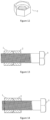
- a shockproof nut kit is shown in Fig.6 to Fig.10 , the structure of a shockproof nut kit is basically the same as that of the one in the Embodiment 1 and the differences thereof lie in that in the present embodiment, the upper end surface of the elliptic cylinder is disposed to be an tapered surface; the cylindrical groove is formed from a truncated cone and a cylinder, the cylinder is served as a guiding surface, and the truncated cone part corresponds with the tapered surface of the elliptic cylinder.
- the specific structure thereof is shown as follows:
- a shockproof nut kit comprising an upper nut 1 and a lower nut 2, in which the outer shape of both the upper nut 1 and the lower nut 2 is hexagonal.
- An end surface of the upper nut 1 is provided with a boss 12 of elliptic cylinder shape
- the inside of the upper nut is provided with a threaded through-hole I 11 of circular structure, that is, the threaded through-hole I 11 is a threaded hole of a cylindrical structure
- the central axis of the elliptic cylinder coincides with that of the threaded through-hole I
- the upper end surface of the elliptic cylinder at either side of the ellipse with longer planar axis is provided with an unfilled corner 13 (Refer to the position E in Fig.8 )
- in an end surface of the lower nut 2 is concavely formed a cylindrical groove 22 matching the boss of elliptic cylinder, the cylindrical groove is formed from a truncated cone and a cylinder, the cylinder serves as a guiding surface, and the truncated cone part matches the elliptic surface of the elliptic cylinder.
- the lower nut is provided with a circular threaded through-hole II 21, namely the threaded through hole II(21) is a threaded hole of a cylindrical structure, the central axis of the cylindrical groove 22 is coincided with that of the threaded through-hole II, and the bore diameter of the threaded through hole I 11 is the same as that of the threaded through hole II 21; and in the assembly state, the boss of elliptic cylinder 12 on the upper nut and a cylindrical groove in the lower nut 22 are in clearance fit with each other, which ensures the coaxiality of the upper and lower nuts in installation to the utmost extent.
- the nut in the present invention could be fabricated into any shapes based on the use purpose, which doesn't affect the service effect.
- the shockproof nut kit deflects the shaking force to the maximum degree by the narrow force bearing surface of an elliptic surface with an unfilled corner of the upper nut so that the upper nut bears only one way shaking force, thereby achieving anti-slipping and shockproof effect.
- the clearance fit of the upper and lower nuts could exempt the nuts from bearing any lateral forces; meanwhile the guiding part of the nut could also resist the inclined force at unfilled corner to ensure the nuts coaxiality to the most extent without slippage during meshing.
Landscapes
- Engineering & Computer Science (AREA)
- General Engineering & Computer Science (AREA)
- Mechanical Engineering (AREA)
- Forging (AREA)
- Transmission Devices (AREA)
- Vibration Dampers (AREA)
- Connection Of Plates (AREA)
- Vibration Prevention Devices (AREA)
- Fluid-Damping Devices (AREA)
Claims (4)
- Ein stoßfestes Muttern-Set bestehend aus einer oberen Mutter (1) und einer unteren Mutter (2), wobei eine Endfläche der oberen Mutter (1) mit einem elliptischen Zylinderförmigen Vorsprung (12) versehen ist; der oberen Mutter hat ein kreisförmiges, durchgehendes Gewindeloch I (11), und die Zentralachse des elliptischen Zylinders fällt mit der durchgehendes Gewindeloch I (11) zusammen, an der oberen Endfläche des elliptischen Zylinders an einer längeren planaren Erweiterungsseite befindet sich eine ungefüllte Ecke (13); in einer Endfläche der unteren Mutter (2) ist eine zylindrische Nut (22) konkav geformt, die zum Vorsprung in elliptischer Zylinderform passt; im Inneren der unteren Mutter befindet sich ein kreisförmiges, durchgehendes Gewindeloch II (21), die Zentralachse der zylindrischen Nut (22) fällt mit der durchgehendes Gewindeloch II (21) zusammen, und der durchgehendes Gewindeloch I (11) ist derselbe wie der durchgehendes Gewindeloch II (21), und nach der Montage passt der Vorsprung (12) in elliptischer Zylinderform auf der oberen Mutter genau in die zylindrische Nut (22) in der unteren Mutter.
- Das stoßfeste Muttern-Set gemäß Anspruch 1, wobei die maximale Öffnungsposition der ungefüllten Ecke (13) bei einem Drittel des durchgehendes Gewindeloch I (11) liegt.
- Das stoßfeste Muttern-Set gemäß Anspruch 1, wobei die obere Endfläche des elliptischen Zylinders als konische Fläche ausgelegt ist; die zylindrische Nut wird durch einen abgestumpften Kegel und einen Zylinder gebildet, wobei der zylindrische Teil als Führungsoberfläche dient und der abgestumpfte Kegelteil mit der konischen Fläche des elliptischen Zylinders übereinstimmt.
- Das stoßfeste Muttern-Set gemäß Anspruch 1, wobei sowohl die äußere Form der oberen Mutter (1) als auch der unteren Mutter (2) sechseckig ist.
Applications Claiming Priority (2)
| Application Number | Priority Date | Filing Date | Title |
|---|---|---|---|
| CN201810875313.XA CN108679073B (zh) | 2018-08-03 | 2018-08-03 | 防震螺母套件 |
| PCT/CN2018/121389 WO2020024524A1 (zh) | 2018-08-03 | 2018-12-17 | 防震螺母套件 |
Publications (4)
| Publication Number | Publication Date |
|---|---|
| EP3832152A1 EP3832152A1 (de) | 2021-06-09 |
| EP3832152A4 EP3832152A4 (de) | 2022-05-11 |
| EP3832152B1 true EP3832152B1 (de) | 2024-03-20 |
| EP3832152C0 EP3832152C0 (de) | 2024-03-20 |
Family
ID=63815297
Family Applications (1)
| Application Number | Title | Priority Date | Filing Date |
|---|---|---|---|
| EP18900570.5A Active EP3832152B1 (de) | 2018-08-03 | 2018-12-17 | Stossfester mutternsatz |
Country Status (6)
| Country | Link |
|---|---|
| US (1) | US11371548B2 (de) |
| EP (1) | EP3832152B1 (de) |
| JP (2) | JP2020532684A (de) |
| KR (1) | KR102334719B1 (de) |
| CN (1) | CN108679073B (de) |
| WO (1) | WO2020024524A1 (de) |
Families Citing this family (7)
| Publication number | Priority date | Publication date | Assignee | Title |
|---|---|---|---|---|
| CN108679073B (zh) * | 2018-08-03 | 2023-11-14 | 周峰 | 防震螺母套件 |
| CN110645254A (zh) * | 2019-09-27 | 2020-01-03 | 周峰 | 端面锥度定心互锁防松螺母套件 |
| CN112943737B (zh) * | 2021-02-04 | 2022-12-02 | 山东锐凯工程机械有限公司 | 一种结构优化式下缸体 |
| WO2022205435A1 (zh) * | 2021-04-02 | 2022-10-06 | 周峰 | 一种端面锥度定心互锁防松螺母套件 |
| JP7173263B1 (ja) | 2021-10-21 | 2022-11-16 | フジテック株式会社 | ナットの取り外し方法及びナットの取り付け方法 |
| CN116241544B (zh) * | 2023-03-21 | 2025-10-17 | 邯郸市浩盛紧固件有限公司 | 一种内卡圈抱紧式防松螺母 |
| KR102717453B1 (ko) * | 2023-11-27 | 2024-10-15 | 문상열 | 신축성 너트 및 그 제작 방법 |
Family Cites Families (34)
| Publication number | Priority date | Publication date | Assignee | Title |
|---|---|---|---|---|
| US262579A (en) * | 1882-08-15 | Lock-nut | ||
| US652530A (en) * | 1899-09-19 | 1900-06-26 | George B Wix | Nut-lock. |
| US738598A (en) * | 1903-06-26 | 1903-09-08 | Charles A Barron | Nut-lock. |
| US1400154A (en) * | 1920-02-19 | 1921-12-13 | Edward A Green | Nut-lock |
| US2285345A (en) * | 1940-06-10 | 1942-06-02 | Albert W Miller | Lock-nut construction |
| US3340920A (en) * | 1964-11-06 | 1967-09-12 | Kenneth L Johnson | Prevailing torque locknut |
| JPS6024568Y2 (ja) * | 1980-10-30 | 1985-07-23 | 東海ゴム工業株式会社 | 竪型射出成形機 |
| JPS6292315U (de) * | 1985-11-29 | 1987-06-12 | ||
| JPS62165012A (ja) * | 1986-10-09 | 1987-07-21 | 株式会社 冨士精密製作所 | ゆるみ止めダブルナット |
| AU639093B2 (en) * | 1990-05-14 | 1993-07-15 | Toyoda Gosei Co. Ltd. | Securing device for manipulated component |
| US20080008556A1 (en) * | 2006-07-05 | 2008-01-10 | Steven Dvorak | Quick Attaching and Detaching Nut |
| WO2009001417A1 (ja) | 2007-06-22 | 2008-12-31 | Hard Lock Industry Co., Ltd. | 緩み止めダブルナット |
| KR101128597B1 (ko) | 2008-02-20 | 2012-03-27 | 히로시 미치와키 | 양나사체 및 암나사체 |
| KR200443393Y1 (ko) | 2008-06-16 | 2009-02-09 | 전기우 | 풀림방지너트 |
| KR20100122548A (ko) * | 2009-05-13 | 2010-11-23 | 오세갑 | 록킹 너트 어셈블리 |
| JP5235237B1 (ja) | 2012-04-19 | 2013-07-10 | イイファス株式会社 | 二重ナット |
| JP2014119000A (ja) | 2012-12-14 | 2014-06-30 | Yoshiaki Yokota | 緩み止めダブルナット |
| CN203009533U (zh) * | 2012-12-29 | 2013-06-19 | 肖在海 | 一种防松螺母 |
| KR101505425B1 (ko) * | 2013-03-14 | 2015-03-25 | 삼성중공업 주식회사 | 풀림방지너트 |
| CN203272396U (zh) * | 2013-05-06 | 2013-11-06 | 邵祥顺 | 一种防松螺母 |
| CN103807271B (zh) * | 2013-11-28 | 2016-01-20 | 芜湖佳景科技有限公司 | 一种防止螺母松动的自锁组合螺母 |
| CN204082860U (zh) * | 2014-05-28 | 2015-01-07 | 中国科学院等离子体物理研究所 | 一种具有防松功能的双螺母结构 |
| JP6437313B2 (ja) | 2015-01-07 | 2018-12-12 | ハードロック工業株式会社 | 緩み止め特殊ダブルナット |
| CN204942222U (zh) * | 2015-09-22 | 2016-01-06 | 江西洪都航空工业集团有限责任公司 | 一种带自锁功能的偏心衬套 |
| WO2017069826A1 (en) * | 2015-10-20 | 2017-04-27 | Limatoc Arnold R | One-piece self-locking nut |
| CN205371256U (zh) * | 2016-01-08 | 2016-07-06 | 太仓中博铁路紧固件有限公司 | 一种安全自锁螺母 |
| JP7014395B2 (ja) * | 2017-03-27 | 2022-02-15 | 株式会社NejiLaw | ねじ体の相対回転抑制構造、相対移動抑制構造、相対移動抑制体 |
| CN206785834U (zh) * | 2017-06-09 | 2017-12-22 | 贵州航太精密制造有限公司 | 一种尾部密封的无耳托板螺母 |
| CN207500304U (zh) | 2017-06-23 | 2018-06-15 | 镇江宏强铁路器材有限公司 | 一种互锁式防松紧固装置 |
| CN108757700A (zh) * | 2018-08-03 | 2018-11-06 | 王平安 | 变形式防松螺母组件 |
| CN108775325A (zh) * | 2018-08-03 | 2018-11-09 | 王平安 | 变形式组合防松螺母 |
| CN108679073B (zh) * | 2018-08-03 | 2023-11-14 | 周峰 | 防震螺母套件 |
| CN208651397U (zh) * | 2018-08-03 | 2019-03-26 | 周峰 | 防震螺母套件 |
| JP3220060U (ja) * | 2018-09-12 | 2019-02-14 | 英二 山中 | 緩まないナット |
-
2018
- 2018-08-03 CN CN201810875313.XA patent/CN108679073B/zh active Active
- 2018-12-17 JP JP2019539950A patent/JP2020532684A/ja active Pending
- 2018-12-17 WO PCT/CN2018/121389 patent/WO2020024524A1/zh not_active Ceased
- 2018-12-17 KR KR1020197021391A patent/KR102334719B1/ko active Active
- 2018-12-17 EP EP18900570.5A patent/EP3832152B1/de active Active
- 2018-12-17 US US16/479,313 patent/US11371548B2/en active Active
-
2021
- 2021-08-20 JP JP2021003245U patent/JP3234710U/ja active Active
Also Published As
| Publication number | Publication date |
|---|---|
| JP2020532684A (ja) | 2020-11-12 |
| WO2020024524A1 (zh) | 2020-02-06 |
| KR20200015441A (ko) | 2020-02-12 |
| US20220003261A1 (en) | 2022-01-06 |
| EP3832152A1 (de) | 2021-06-09 |
| JP3234710U (ja) | 2021-10-28 |
| CN108679073A (zh) | 2018-10-19 |
| EP3832152A4 (de) | 2022-05-11 |
| CN108679073B (zh) | 2023-11-14 |
| EP3832152C0 (de) | 2024-03-20 |
| US11371548B2 (en) | 2022-06-28 |
| KR102334719B1 (ko) | 2021-12-07 |
Similar Documents
| Publication | Publication Date | Title |
|---|---|---|
| EP3832152B1 (de) | Stossfester mutternsatz | |
| US4195944A (en) | Frictional couplings | |
| CN110805607A (zh) | 一种防松止退可靠的螺钉组件 | |
| US5035544A (en) | Insert clamped tool | |
| CN101438066A (zh) | 冲孔螺母及其用途 | |
| WO2020237910A1 (zh) | 一种防松螺杆螺母组件 | |
| CN210509906U (zh) | 端面锥度定心互锁防松螺母套件 | |
| WO2021057534A1 (zh) | 端面锥度定心互锁防松螺母套件 | |
| CN210240270U (zh) | 一种自锁紧固件 | |
| CN213870688U (zh) | 圆弧定心防松螺母 | |
| CN215214321U (zh) | 弹性自锁螺母 | |
| CN208651397U (zh) | 防震螺母套件 | |
| CN208749787U (zh) | 一种通用组合防松螺母 | |
| JP2000304010A (ja) | 被固定部材の固定部材への取り付け構造 | |
| CA1166048A (en) | Hexagon socket head bolt | |
| CN208793456U (zh) | 一种一体式联轴套 | |
| CN209458261U (zh) | 单侧避空椭圆防震螺母套件 | |
| CN222415945U (zh) | 活塞杆组件的防松结构 | |
| CN112727896A (zh) | 弹性自锁螺母 | |
| JP3244958U (ja) | 自動固定ネジ | |
| CN222084920U (zh) | 一种防松螺栓组件 | |
| CN219262923U (zh) | 螺栓 | |
| CN217421807U (zh) | 一种轧机万向轴用高强度螺栓 | |
| CN216812431U (zh) | 一种便于拆卸的高强度弹性销 | |
| CN222797880U (zh) | 一种内双舌止动垫圈和螺纹紧固结构 |
Legal Events
| Date | Code | Title | Description |
|---|---|---|---|
| STAA | Information on the status of an ep patent application or granted ep patent |
Free format text: STATUS: UNKNOWN |
|
| STAA | Information on the status of an ep patent application or granted ep patent |
Free format text: STATUS: THE INTERNATIONAL PUBLICATION HAS BEEN MADE |
|
| PUAI | Public reference made under article 153(3) epc to a published international application that has entered the european phase |
Free format text: ORIGINAL CODE: 0009012 |
|
| STAA | Information on the status of an ep patent application or granted ep patent |
Free format text: STATUS: THE APPLICATION HAS BEEN PUBLISHED |
|
| STAA | Information on the status of an ep patent application or granted ep patent |
Free format text: STATUS: REQUEST FOR EXAMINATION WAS MADE |
|
| 17P | Request for examination filed |
Effective date: 20191204 |
|
| AK | Designated contracting states |
Kind code of ref document: A1 Designated state(s): AL AT BE BG CH CY CZ DE DK EE ES FI FR GB GR HR HU IE IS IT LI LT LU LV MC MK MT NL NO PL PT RO RS SE SI SK SM TR |
|
| DAV | Request for validation of the european patent (deleted) | ||
| DAX | Request for extension of the european patent (deleted) | ||
| A4 | Supplementary search report drawn up and despatched |
Effective date: 20220408 |
|
| RIC1 | Information provided on ipc code assigned before grant |
Ipc: F16B 39/00 20060101ALI20220404BHEP Ipc: F16B 39/08 20060101AFI20220404BHEP |
|
| STAA | Information on the status of an ep patent application or granted ep patent |
Free format text: STATUS: EXAMINATION IS IN PROGRESS |
|
| 17Q | First examination report despatched |
Effective date: 20221018 |
|
| GRAP | Despatch of communication of intention to grant a patent |
Free format text: ORIGINAL CODE: EPIDOSNIGR1 |
|
| STAA | Information on the status of an ep patent application or granted ep patent |
Free format text: STATUS: GRANT OF PATENT IS INTENDED |
|
| INTG | Intention to grant announced |
Effective date: 20230926 |
|
| GRAS | Grant fee paid |
Free format text: ORIGINAL CODE: EPIDOSNIGR3 |
|
| GRAA | (expected) grant |
Free format text: ORIGINAL CODE: 0009210 |
|
| STAA | Information on the status of an ep patent application or granted ep patent |
Free format text: STATUS: THE PATENT HAS BEEN GRANTED |
|
| AK | Designated contracting states |
Kind code of ref document: B1 Designated state(s): AL AT BE BG CH CY CZ DE DK EE ES FI FR GB GR HR HU IE IS IT LI LT LU LV MC MK MT NL NO PL PT RO RS SE SI SK SM TR |
|
| RAP3 | Party data changed (applicant data changed or rights of an application transferred) |
Owner name: ZHOU, FENG |
|
| REG | Reference to a national code |
Ref country code: GB Ref legal event code: FG4D |
|
| RIN1 | Information on inventor provided before grant (corrected) |
Inventor name: ZHOU, FENG |
|
| REG | Reference to a national code |
Ref country code: CH Ref legal event code: EP |
|
| REG | Reference to a national code |
Ref country code: DE Ref legal event code: R096 Ref document number: 602018067024 Country of ref document: DE |
|
| REG | Reference to a national code |
Ref country code: IE Ref legal event code: FG4D |
|
| U01 | Request for unitary effect filed |
Effective date: 20240418 |
|
| U07 | Unitary effect registered |
Designated state(s): AT BE BG DE DK EE FI FR IT LT LU LV MT NL PT SE SI Effective date: 20240423 |
|
| PG25 | Lapsed in a contracting state [announced via postgrant information from national office to epo] |
Ref country code: GR Free format text: LAPSE BECAUSE OF FAILURE TO SUBMIT A TRANSLATION OF THE DESCRIPTION OR TO PAY THE FEE WITHIN THE PRESCRIBED TIME-LIMIT Effective date: 20240621 |
|
| PG25 | Lapsed in a contracting state [announced via postgrant information from national office to epo] |
Ref country code: RS Free format text: LAPSE BECAUSE OF FAILURE TO SUBMIT A TRANSLATION OF THE DESCRIPTION OR TO PAY THE FEE WITHIN THE PRESCRIBED TIME-LIMIT Effective date: 20240620 Ref country code: HR Free format text: LAPSE BECAUSE OF FAILURE TO SUBMIT A TRANSLATION OF THE DESCRIPTION OR TO PAY THE FEE WITHIN THE PRESCRIBED TIME-LIMIT Effective date: 20240320 |
|
| PG25 | Lapsed in a contracting state [announced via postgrant information from national office to epo] |
Ref country code: RS Free format text: LAPSE BECAUSE OF FAILURE TO SUBMIT A TRANSLATION OF THE DESCRIPTION OR TO PAY THE FEE WITHIN THE PRESCRIBED TIME-LIMIT Effective date: 20240620 Ref country code: NO Free format text: LAPSE BECAUSE OF FAILURE TO SUBMIT A TRANSLATION OF THE DESCRIPTION OR TO PAY THE FEE WITHIN THE PRESCRIBED TIME-LIMIT Effective date: 20240620 Ref country code: HR Free format text: LAPSE BECAUSE OF FAILURE TO SUBMIT A TRANSLATION OF THE DESCRIPTION OR TO PAY THE FEE WITHIN THE PRESCRIBED TIME-LIMIT Effective date: 20240320 Ref country code: GR Free format text: LAPSE BECAUSE OF FAILURE TO SUBMIT A TRANSLATION OF THE DESCRIPTION OR TO PAY THE FEE WITHIN THE PRESCRIBED TIME-LIMIT Effective date: 20240621 |
|
| PG25 | Lapsed in a contracting state [announced via postgrant information from national office to epo] |
Ref country code: IS Free format text: LAPSE BECAUSE OF FAILURE TO SUBMIT A TRANSLATION OF THE DESCRIPTION OR TO PAY THE FEE WITHIN THE PRESCRIBED TIME-LIMIT Effective date: 20240720 |
|
| PG25 | Lapsed in a contracting state [announced via postgrant information from national office to epo] |
Ref country code: SM Free format text: LAPSE BECAUSE OF FAILURE TO SUBMIT A TRANSLATION OF THE DESCRIPTION OR TO PAY THE FEE WITHIN THE PRESCRIBED TIME-LIMIT Effective date: 20240320 |
|
| PG25 | Lapsed in a contracting state [announced via postgrant information from national office to epo] |
Ref country code: ES Free format text: LAPSE BECAUSE OF FAILURE TO SUBMIT A TRANSLATION OF THE DESCRIPTION OR TO PAY THE FEE WITHIN THE PRESCRIBED TIME-LIMIT Effective date: 20240320 |
|
| PG25 | Lapsed in a contracting state [announced via postgrant information from national office to epo] |
Ref country code: CZ Free format text: LAPSE BECAUSE OF FAILURE TO SUBMIT A TRANSLATION OF THE DESCRIPTION OR TO PAY THE FEE WITHIN THE PRESCRIBED TIME-LIMIT Effective date: 20240320 |
|
| PG25 | Lapsed in a contracting state [announced via postgrant information from national office to epo] |
Ref country code: PL Free format text: LAPSE BECAUSE OF FAILURE TO SUBMIT A TRANSLATION OF THE DESCRIPTION OR TO PAY THE FEE WITHIN THE PRESCRIBED TIME-LIMIT Effective date: 20240320 |
|
| PG25 | Lapsed in a contracting state [announced via postgrant information from national office to epo] |
Ref country code: SK Free format text: LAPSE BECAUSE OF FAILURE TO SUBMIT A TRANSLATION OF THE DESCRIPTION OR TO PAY THE FEE WITHIN THE PRESCRIBED TIME-LIMIT Effective date: 20240320 |
|
| PG25 | Lapsed in a contracting state [announced via postgrant information from national office to epo] |
Ref country code: SM Free format text: LAPSE BECAUSE OF FAILURE TO SUBMIT A TRANSLATION OF THE DESCRIPTION OR TO PAY THE FEE WITHIN THE PRESCRIBED TIME-LIMIT Effective date: 20240320 Ref country code: SK Free format text: LAPSE BECAUSE OF FAILURE TO SUBMIT A TRANSLATION OF THE DESCRIPTION OR TO PAY THE FEE WITHIN THE PRESCRIBED TIME-LIMIT Effective date: 20240320 Ref country code: RO Free format text: LAPSE BECAUSE OF FAILURE TO SUBMIT A TRANSLATION OF THE DESCRIPTION OR TO PAY THE FEE WITHIN THE PRESCRIBED TIME-LIMIT Effective date: 20240320 Ref country code: PL Free format text: LAPSE BECAUSE OF FAILURE TO SUBMIT A TRANSLATION OF THE DESCRIPTION OR TO PAY THE FEE WITHIN THE PRESCRIBED TIME-LIMIT Effective date: 20240320 Ref country code: IS Free format text: LAPSE BECAUSE OF FAILURE TO SUBMIT A TRANSLATION OF THE DESCRIPTION OR TO PAY THE FEE WITHIN THE PRESCRIBED TIME-LIMIT Effective date: 20240720 Ref country code: ES Free format text: LAPSE BECAUSE OF FAILURE TO SUBMIT A TRANSLATION OF THE DESCRIPTION OR TO PAY THE FEE WITHIN THE PRESCRIBED TIME-LIMIT Effective date: 20240320 Ref country code: CZ Free format text: LAPSE BECAUSE OF FAILURE TO SUBMIT A TRANSLATION OF THE DESCRIPTION OR TO PAY THE FEE WITHIN THE PRESCRIBED TIME-LIMIT Effective date: 20240320 |
|
| REG | Reference to a national code |
Ref country code: DE Ref legal event code: R097 Ref document number: 602018067024 Country of ref document: DE |
|
| PLBE | No opposition filed within time limit |
Free format text: ORIGINAL CODE: 0009261 |
|
| STAA | Information on the status of an ep patent application or granted ep patent |
Free format text: STATUS: NO OPPOSITION FILED WITHIN TIME LIMIT |
|
| U20 | Renewal fee for the european patent with unitary effect paid |
Year of fee payment: 7 Effective date: 20241231 |
|
| 26N | No opposition filed |
Effective date: 20241223 |
|
| PG25 | Lapsed in a contracting state [announced via postgrant information from national office to epo] |
Ref country code: MC Free format text: LAPSE BECAUSE OF FAILURE TO SUBMIT A TRANSLATION OF THE DESCRIPTION OR TO PAY THE FEE WITHIN THE PRESCRIBED TIME-LIMIT Effective date: 20240320 |
|
| REG | Reference to a national code |
Ref country code: CH Ref legal event code: PL |
|
| GBPC | Gb: european patent ceased through non-payment of renewal fee |
Effective date: 20241217 |
|
| PG25 | Lapsed in a contracting state [announced via postgrant information from national office to epo] |
Ref country code: GB Free format text: LAPSE BECAUSE OF NON-PAYMENT OF DUE FEES Effective date: 20241217 |
|
| PG25 | Lapsed in a contracting state [announced via postgrant information from national office to epo] |
Ref country code: CH Free format text: LAPSE BECAUSE OF NON-PAYMENT OF DUE FEES Effective date: 20241231 |
|
| PG25 | Lapsed in a contracting state [announced via postgrant information from national office to epo] |
Ref country code: IE Free format text: LAPSE BECAUSE OF NON-PAYMENT OF DUE FEES Effective date: 20241217 |
|
| U20 | Renewal fee for the european patent with unitary effect paid |
Year of fee payment: 8 Effective date: 20251219 |
|
| U1K | Transfer of rights of the unitary patent after the registration of the unitary effect |
Owner name: ZHEJIANG JIANFAN SPECIAL FASTENERS CO., LTD; CN |