EP3831758A1 - Multi-car elevator system - Google Patents
Multi-car elevator system Download PDFInfo
- Publication number
- EP3831758A1 EP3831758A1 EP19844665.0A EP19844665A EP3831758A1 EP 3831758 A1 EP3831758 A1 EP 3831758A1 EP 19844665 A EP19844665 A EP 19844665A EP 3831758 A1 EP3831758 A1 EP 3831758A1
- Authority
- EP
- European Patent Office
- Prior art keywords
- boarding
- platform
- car
- group
- waiting position
- Prior art date
- Legal status (The legal status is an assumption and is not a legal conclusion. Google has not performed a legal analysis and makes no representation as to the accuracy of the status listed.)
- Granted
Links
Images







Classifications
-
- B—PERFORMING OPERATIONS; TRANSPORTING
- B66—HOISTING; LIFTING; HAULING
- B66B—ELEVATORS; ESCALATORS OR MOVING WALKWAYS
- B66B3/00—Applications of devices for indicating or signalling operating conditions of elevators
- B66B3/002—Indicators
- B66B3/006—Indicators for guiding passengers to their assigned elevator car
-
- B—PERFORMING OPERATIONS; TRANSPORTING
- B66—HOISTING; LIFTING; HAULING
- B66B—ELEVATORS; ESCALATORS OR MOVING WALKWAYS
- B66B1/00—Control systems of elevators in general
- B66B1/24—Control systems with regulation, i.e. with retroactive action, for influencing travelling speed, acceleration, or deceleration
- B66B1/2408—Control systems with regulation, i.e. with retroactive action, for influencing travelling speed, acceleration, or deceleration where the allocation of a call to an elevator car is of importance, i.e. by means of a supervisory or group controller
- B66B1/2433—For elevator systems with a single shaft and multiple cars
-
- B—PERFORMING OPERATIONS; TRANSPORTING
- B66—HOISTING; LIFTING; HAULING
- B66B—ELEVATORS; ESCALATORS OR MOVING WALKWAYS
- B66B1/00—Control systems of elevators in general
- B66B1/24—Control systems with regulation, i.e. with retroactive action, for influencing travelling speed, acceleration, or deceleration
- B66B1/2408—Control systems with regulation, i.e. with retroactive action, for influencing travelling speed, acceleration, or deceleration where the allocation of a call to an elevator car is of importance, i.e. by means of a supervisory or group controller
- B66B1/2466—For elevator systems with multiple shafts and multiple cars per shaft
-
- B—PERFORMING OPERATIONS; TRANSPORTING
- B66—HOISTING; LIFTING; HAULING
- B66B—ELEVATORS; ESCALATORS OR MOVING WALKWAYS
- B66B1/00—Control systems of elevators in general
- B66B1/34—Details, e.g. call counting devices, data transmission from car to control system, devices giving information to the control system
- B66B1/46—Adaptations of switches or switchgear
- B66B1/468—Call registering systems
Definitions
- the present invention relates to a multi-car elevator system that controls a multi-car elevator in which a plurality of cars move in a moving path.
- a multi-car elevator has been proposed in which a plurality of cars move in one moving path.
- the plurality of cars with different destinations stop at the same platform. Therefore, every time the car stops at the platform, the passenger needs to decide whether to get on the car.
- PTL 1 a car is assigned according to the destination floor input by the passenger, and when the assigned car is approaching the departure floor, an identification code is displayed in one of signs adjacent to the hoist way where the assigned car travels.
- An object of the invention is to provide a multi-car elevator system that can reduce the burden of passengers' boarding decisions in consideration of the above problems.
- the multi-car elevator system is a multi-car elevator system that controls a multi-car elevator in which a plurality of cars move in the same moving path.
- the multi-car elevator system includes a call input display unit, a group management control unit, and a car control unit.
- the call input display unit is provided in the platform hall where the car stops, and the destination is input by the passenger.
- the group management control unit receives destination information regarding the passenger's destination transmitted from the call input display unit, and assigns a specific boarding group to the passenger from among a plurality of boarding groups based on the destination information.
- the car control unit controls the movement of the car, and transmits the movement information regarding the movement of the car to the group management control unit.
- the group management control unit calculates boarding guidance information, which is information regarding the car to be boarded by the passenger, for each of the plurality of boarding groups based on the movement information received from the car control unit, and outputs the information to the outside.
- FIGS. 1 to 21 The common members in each drawing are designated by the same reference numerals.
- this example the configuration of the multi-car elevator system according to a first embodiment (hereinafter, referred to as "this example") will be described with reference to FIG. 1 .
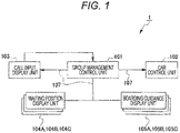
- FIG. 1 is a block diagram illustrating a schematic configuration of the multi-car elevator system of this example.
- a multi-car elevator system 1 illustrated in FIG. 1 is a system that controls and guides boarding on the multi-car elevator 10 (see FIG. 2 ) in which a plurality of cars 11A to 11G move in one moving path 5 formed in a building structure.
- the multi-car elevator system 1 includes a group management control unit 101, a car control unit 102, a call input display unit 103, a plurality of waiting position display units 104A, 104B, and 104C, and a plurality of boarding guidance display units 105A, 105B, and 105C.
- the group management control unit 101, the car control unit 102, the call input display unit 103, and the plurality of boarding guidance display units 105A, 105B, and 105C are connected to each other via a system bus 107 so that information can be transmitted and received. Then, the group management control unit 101 controls the entire system.
- the group management control unit 101 has, for example, a CPU (Central Processing Unit), a RAM (Random Access Memory), and a ROM (Read Only Memory) .
- the RAM is used as the work area of the CPU, and the ROM stores programs executed by the CPU.
- the group management control unit 101 receives movement information of a car, opening/closing information of an opening/closing door from the car control unit 102, and receives destination information of a passenger from the call input display unit 103.
- the group management control unit 101 performs a boarding group allocation process on passengers to assign a specific boarding group from among a plurality of boarding groups based on the destination information received from the call input display unit 103.
- the group management control unit 101 calculates a departure group list based on the movement information of the car from the car control unit 102 and the boarding group information, and outputs boarding guidance information to each of the boarding guidance display units 105A, 105B, and 105C.
- the boarding group allocation process and the departure group list calculation process in the group management control unit 101 will be described later.
- the car control unit 102 controls the movement of the plurality of cars 11A to 11G (see FIG. 2 ) moving along the moving path, and controls the opening and closing of the opening/closing doors provided in the cars 11A to 11G. Further, the car control unit 102 transmits the movement information of the cars 11A to 11G and the opening/closing information of the opening/closing door to the group management control unit 101.
- the call input display unit 103, the waiting position display units 104A, 104B, and 104C, and the boarding guidance display units 105A, 105B, and 105C are provided in a platform hall 50 (see FIG. 3 etc.) which is provided on each floor of the building structure for a passenger to board or alight.
- the call input display unit 103 includes an input unit through which the passenger inputs a destination, and a display unit 103a (see FIG. 3 ) that displays the assigned boarding group.
- the call input display unit 103 transmits the destination information and the call information for calling a car to the input platform hall to the group management control unit 101. Further, the call input display unit 103 receives the boarding group information calculated by the group management control unit 101. This boarding group information is boarding group information for a passenger who has entered the destination. Then, the call input display unit 103 displays an identifier for identifying the boarding group in the display unit based on the received boarding group information, and notifies the passenger who has input the destination of the boarding group.
- the identifier for identifying the boarding group is indicated by, for example, any one or a plurality of combinations of a mechanism, characters, colors, patterns, and the like.
- the call input display unit 103 is configured by, for example, a touch panel, a key input unit, a reading unit for reading tags and cards possessed by passengers, and the like.
- the boarding group is an individual, a group heading to the same floor, a group heading to the same zone by grouping multiple floors as one zone, a group determined by the multi-car elevator system 1, and the like.
- the waiting position display units 104A, 104B, and 104C and the boarding guidance display units 105A, 105B, and 105C are provided for each boarding group.
- the detailed configurations of the waiting position display units 104A, 104B, and 104C and the boarding guidance display units 105A, 105B, and 105C will be described later.
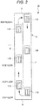
- FIG. 2 is a schematic configuration diagram illustrating an example of a multi-car elevator controlled by the multi-car elevator system 1 of this example.
- a multi-car elevator 10 includes a plurality of cars 11A, 11B, 11C, 11D, 11E, and 11F for carrying people and luggage, and a drive unit (not illustrated).
- the plurality of cars 11A to 11F circulate in the moving path 5 provided in the building structure.
- the moving path 5 is provided with an ascending path 6 indicating a first moving path in which the cars 11A to 11F move upward and a descending path 7 indicating a second moving path in which the cars 11A to 11G move downward.
- a first reversing path 8 is provided in which the movement of the cars 11A to 11F is reversed from ascending to descending.
- a second reversing path 9 is provided in which the movement of the cars 11A to 11F is reversed from descending to ascending.
- the plurality of cars 11A to 11F are driven by the drive unit and circulate in the ascending path 6, the descending path 7, the first reversing path 8, and the second reversing path 9 in the moving path 5.
- the multi-car elevator 10 in which the plurality of cars 11A to 11F circulate and move has been described, but the invention is not limited to this.
- it can be applied to a multi-car elevator in which a plurality of cars can move up and down the moving path in both directions.
- a driving method for the cars 11A to 11F of the multi-car elevator 10 there may be used a driving method provided with a hoisting machine and a driving method in which a linear drive unit is provided and an induced current flows to the main rope connected to the cars 11A to 11F to generate a driving force (thrust) in the main rope itself. It can also be applied to self-propelled multi-car elevators with drive units on the cars 11A to 11F.
- the number of cars provided in the multi-car elevator 10 is not limited to 6, and the number of cars may be 5 or less, or 7 or more.
- FIGS. 3 to 9 An example of boarding guidance in the multi-car elevator system 1 of this example will be described with reference to FIGS. 3 to 9 .
- the dotted lines illustrated in FIGS. 3 to 9 indicate a state in which the boarding guidance display unit is turned off.
- FIG. 3 a first configuration example of the platform hall will be described with reference to FIGS. 3 and 4 .
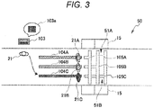
- FIG. 3 is an explanatory diagram illustrating a first configuration example of the platform hall.
- the platform hall 50 illustrated in FIG. 3 there are provided two platforms 51A and 51B where the passenger 21 gets on and off the cars 11A to 11G.
- the first platform 51A and the second platform 51B are located opposite each other in the platform hall 50.
- the first platform 51A and the second platform 51B each are provided with entrances for the passenger 21 to get on and off the cars 11A to 11G. Further, at this entrance, a platform door 15 is installed so that it can be opened and closed.
- the passenger 21 comes in and out the platform hall 50 from the side of the first platform 51A and the second platform 51B, which are orthogonal to the direction in which the first platform 51A and the second platform 51B face each other. Therefore, the entrances of the platform hall 50 are arranged on the sides of the first platform 51A and the second platform 51B.
- the call input display unit 103 the plurality of waiting position display units 104A, 104B, and 104C, and the boarding guidance display units 105A, 105B, and 105C are installed.
- the call input display unit 103 is installed at the entrance of the platform hall 50.
- the waiting position display units 104A, 104B, and 104C and the boarding guidance display units 105A, 105B, and 105C are installed between the call input display unit 103 and the first platform 51A and the second platform 51B.
- the call input display unit 103 transmits the destination information and the call information to the group management control unit 101. Then, the call input display unit 103 receives the boarding group information calculated by the group management control unit 101, and displays the identifier on the display unit based on the boarding group information. As a result, the passenger 21 comes to know that it is better to stand at which of the waiting position display units 104A, 104B, and 104C among the plurality of waiting position display units 104A, 104B, and 104C by the identifier displayed in the call input display unit 103.
- the waiting position display units 104A, 104B, and 104C are at standby positions for the passenger 21 who has input the destination to the call input display unit 103 to wait for the cars 11A to 11G.
- the waiting position display units 104A, 104B, and 104C are formed on the floor surface of the platform hall 50 for each of the assigned boarding groups 21A, 21B, and 21C.
- the first waiting position display unit 104A corresponds to the first boarding group 21A
- the second waiting position display unit 104B corresponds to the second boarding group 21B
- the third waiting position display unit 104C corresponds to the third boarding group 21C.
- the waiting position display units 104A, 104B, and 104C are formed substantially parallel to the direction orthogonal to the direction in which the first platform 51A and the second platform 51B face each other.
- the waiting position display units 104A, 104B, and 104C may be formed by embedding an LED, a phosphorescent member, or the like in the floor surface, or may be drawn on the floor surface with paint. Further, the waiting position display units 104A, 104B, and 104C may be formed by attaching a sticker to the floor surface, or may be formed by various other guidance methods.
- the invention is not limited to this.
- the waiting position display units 104A, 104B, and 104C for example, the display screen of one display device may be divided into the waiting position display units 104A, 104B, and 104C.
- the boarding guidance display units 105A, 105B, and 105C are formed on the floor surface of the platform hall 50.
- the boarding guidance display units 105A, 105B, and 105C are arranged at the head of the standby position in the corresponding waiting position display units 104A, 104B, and 104C.
- the first boarding guidance display unit 105A is visibly arranged with respect to the first boarding group 21A on standby in the first waiting position display unit 104A.
- the second boarding guidance display unit 105B is visibly arranged with respect to the second boarding group 21B on standby in the second waiting position display unit 104B
- the third boarding guidance display unit 105C is visibly arranged with respect to the third boarding group 21C on standby in the third waiting position display unit 104C.
- the boarding guidance display units 105A, 105B, and 105C are, for example, light emitting display devices such as LEDs and liquid crystal panels embedded in the floor surface of the platform hall 50.
- the boarding guidance display units 105A, 105B, and 105C are turned off, turned on, and blinked based on the boarding guidance information output from the group management control unit 101. Then, the boarding guidance display units 105A, 105B, and 105C guide the corresponding boarding groups 21A, 21B, and 21C to the platforms 51A and 51B for the boarding by turning on or blinking.
- FIG. 4 is an explanatory diagram illustrating a first boarding guidance example.
- the group management control unit 101 transmits the boarding guidance information to the boarding guidance display units 105A, 105B, and 105C.
- the boarding guidance display units 105A, 105B, and 105C is turned on or blink based on the boarding guidance information received from the group management control unit 101, and guide the corresponding boarding groups 21A, 21B, and 21C to the platforms 51A and 51B to be boarded.
- the first boarding group 21A is assigned to the first platform 51A
- the second boarding group 21B and the third boarding group 21C are assigned to the second platform 51B.
- the first boarding guidance display unit 105A is turned on or blinks from the head of the first waiting position display unit 104A to the first platform 51A.
- the second boarding guidance display unit 105B is turned on or blinks from the head of the second waiting position display unit 104B to the second platform 51B
- the third boarding guidance display unit 105C is turned on or blinks from the head of the third waiting position display unit 104C to the second platform 51B.
- the passenger of the first boarding group 21A comes to know that it is better to get on the car stopped at the first platform 51A by the first boarding guidance display unit 105A.
- the passengers of the second boarding group 21B and the passengers of the third boarding group 21C may come to know that it is better to get on the car stopped at the second platform 51B by the second boarding guidance display unit 105B and the third boarding guidance display unit 105C.
- the passenger 21 can easily determine a car to get on based on the display contents of the boarding guidance display units 105A, 105B, and 105C arranged at the head of each of the waiting position display units 104A, 104B, and 104C. As a result, the burden of the passenger 21 on boarding decision can be reduced.
- FIG. 5 is an explanatory diagram illustrating a second configuration example of the platform hall.
- FIG. 5 illustrates a state in which the cars are stopped at the platforms 51A and 51B.
- the portions common to the platform hall 50 according to the first configuration example are designated by the same reference numerals, and duplicate description will be omitted.
- two platforms 51A and 51B are provided as in the platform hall 50 of the first configuration example.
- the first platform 51A and the second platform 51B are arranged side by side.
- a call input display unit 203 a plurality of waiting position display units 204A, 204B, and 204C, and boarding guidance display units 205A, 205B, and 205C are installed.
- the boarding guidance display units 205A, 205B, and 205C are arranged from the head of the standby position in the corresponding waiting position display units 204A, 204B, and 204C to the first platform 51A and the second platform 51B.
- the first boarding group 21A is assigned to the first platform 51A
- the third boarding group 21C is assigned to the second platform 51B.
- the second boarding group 21B is in a standby state without getting on the car arriving at the first platform 51A and the second platform 51B this time.
- the first boarding guidance display unit 205A is turned on or blinks from the first waiting position display unit 204A to the first platform 51A, and the third boarding guidance display unit 205C is turned on or blinks from the third waiting position display unit 204C to the second platform 51B. Then, the second boarding guidance display unit 205B is turned off.
- the second boarding group 21B can know that it is better not to get on the car arriving at the first platform 51A and the second platform 51B this time.
- the first boarding group 21A can know that it is better to get on the car stopped at the first platform 51A based on the display contents of the first boarding guidance display unit 205A
- the third boarding group 21C can know that it is better to get on the car stopped at the second platform 51B based on the display contents of the third boarding guidance display unit 205C.
- the passenger can easily determine a car to be boarded based on the display contents of the boarding guidance display units 205A to 205B.
- FIG. 6 is an explanatory diagram illustrating a third configuration example of the platform hall.
- FIG. 6 illustrates a state in which the car is stopped at the platforms 51A and 51B.
- the portions common to the platform hall 50 according to the first configuration example are designated by the same reference numerals, and duplicate description will be omitted.
- a platform hall 70 according to the third configuration example illustrated in FIG. 6 two platforms 51A and 51B are provided as in the platform hall 50 according to the first configuration example.
- the first platform 51A and the second platform 51B are arranged side by side in the same manner as the platform hall 60 in the second configuration example.
- the passenger 21 enters and exits the platform hall 70 from the direction facing the first platform 51A and the second platform 51B. Therefore, the entrance of the platform hall 70 is located in front of the first platform 51A and the second platform 51B.
- a call input display unit 303 is installed in the platform hall 70.
- the call input display unit 303 is arranged at a position facing the first platform 51A and the second platform 51B, which are the entrances and exits of the platform hall 70.
- the waiting position display units 304A, 304B, and 304C are formed in front of the first platform 51A and the second platform 51B in parallel with the direction facing the first platform 51A and the second platform 51B. Further, the waiting position display units 304A, 304B, and 304C are arranged at intermediate positions in the direction in which the first platform 51A and the second platform 51B are aligned. The boarding guidance display units 305A, 305B, and 305C are arranged between the waiting position display units 304A, 304B, and 304C and the first platform 51A and the second platform 51B.
- the first boarding group 21A and the second boarding group 21B are assigned to the first platform 51A
- the third boarding group 21C is assigned to the second platform 51B. Therefore, the first boarding guidance display unit 305A is turned on or blinks from the first waiting position display unit 304A to the first platform 51A, and the second boarding guidance display unit 305B is turned on or blinks from the second waiting position display unit 304B to the first platform 51A.
- the third boarding guidance display unit 305C is turned on or blinking from the third waiting position display unit 304C to the second platform 51B.
- the passenger can easily determine the car to be boarded based on the display contents of the boarding guidance display units 305A to 305C.
- FIG. 7 is an explanatory diagram illustrating a fourth configuration example of the platform hall.
- FIG. 7 illustrates a state in which the car is stopped at a platform 51.
- the portions common to the platform hall 50 according to the first configuration example are designated by the same reference numerals, and duplicate description will be omitted.
- a platform hall 80 according to the fourth configuration example illustrated in FIG. 7 only one platform 51 is provided. Further, the entrance of the platform hall 80 is arranged in front of the platform 51 as in the platform hall 70 according to the third configuration example.
- a call input display unit 403 In the platform hall 80 a call input display unit 403, waiting position display units 404A, 404B, and 404C, and boarding guidance display units 405A, 405B, and 405C are installed.
- the call input display unit 403 is arranged at a position facing the platform 51, which is the entrance of the platform hall 80.
- the waiting position display units 404A, 404B, and 404C are formed in front of the platform 51 in parallel with the direction facing the platform 51.
- the boarding guidance display units 405A, 405B, and 405C are arranged between the waiting position display units 404A, 404B, and 404C and the platform 51.
- the boarding guidance display units 405A, 405B, and 405C extend from the head of the corresponding waiting position display units 404A, 404B, and 404C to the platform 51.
- the first boarding group 21A and the third boarding group 21C are assigned to get on the car arriving at the platform 51 this time. Then, the second boarding group 21B is in a standby state without boarding the car that has arrived at the platform 51 this time.
- the first boarding guidance display unit 405 and the third boarding guidance display unit 405C are turned on or blinking, and the second boarding guidance display unit 405B is turned off.
- the passengers of the first boarding group 21A and the third boarding group 21C know that it is better to get on the arrived car based on the display contents of the first boarding guidance display unit 405A and the third boarding guidance display unit 405C.
- the passenger of the second boarding group 21B knows that it is not better to get on the arrived car this time based on the display contents of the second boarding guidance display unit 405B.
- the passenger can easily determine the car to be boarded based on the display contents of the boarding guidance display units 405A to 405C.
- FIG. 8 is an explanatory diagram illustrating a fifth configuration example of the platform hall.
- FIG. 8 illustrates a state in which the cars are stopped at the platforms 51A and 51B.
- the portions common to the platform hall 50 according to the first configuration example are designated by the same reference numerals, and duplicate description will be omitted.
- a platform hall 90 according to the fifth configuration example the first platform 51A and the second platform 51B are arranged side by side in the same manner as the platform halls 60 and 70 according to the second configuration example and the third configuration example.
- the entrance of the platform hall 90 is arranged in front of the first platform 51A and the second platform 51B, as in the platform hall 70 according to the third configuration example.
- a call input display unit 503 In the platform hall 80, a call input display unit 503, waiting position display units 504A, 504B, 504C, 504D, 504E, and 504F, and boarding guidance display units 505A, 505B, 505C, 505D, 505E, and 505F are installed.
- the first waiting position display unit 504A, the second waiting position display unit 504B, and the third waiting position display unit 504C are formed in front of the first platform 51A.
- the fourth waiting position display unit 504D, the fifth waiting position display unit 504E, and the sixth waiting position display unit 504F are formed in front of the second platform 51B.
- the first boarding guidance display unit 505A extends from the head of the first waiting position display unit 504A to the first platform 51A
- the second boarding guidance display unit 505B extends from the head of the second waiting position display unit 504B to the first platform 51A
- the third boarding guidance display unit 505C extends from the head of the third waiting position display unit 504C to the first platform 51A.
- the fourth boarding guidance display unit 505D extends from the head of the fourth waiting position display unit 504D to the second platform 51B
- the fifth boarding guidance display unit 505E extends from the head of the fifth waiting position display unit 504E to the second platform 51B
- the sixth boarding guidance display unit 505F extends from the head of the sixth waiting position display unit 504F to the second platform 51B.
- the waiting position display units 504A to 504F and the boarding guidance display units 505A to 505F are provided for each of the platforms 51A and 51B.
- the call input display unit 503 displays an identifier based on the boarding group.
- the group management control unit 101 determines the boarding group, the platform for getting on the car is also determined at the same time. That is, when the passengers 21 are assigned to the first boarding group 21A, the second boarding group 21B, and the third boarding group 21C, the group management control unit 101 assigns the passengers to board from the first platform 51A at the same time. Then, when the passengers 21 are assigned to the fourth boarding group 21D, the fifth boarding group 21E, and the sixth boarding group 21F, the group management control unit 101 assigns the passengers to board from the second platform 51B at the same time.
- the first boarding group and the third boarding group 21C assigned to the first platform 51A are assigned to get on the car that has arrived at the first platform 51A this time. Then, the second boarding group 21B assigned to the first platform 51A is in a standby state without getting on the car that has arrived at the first platform 51A this time.
- the fifth boarding group 21E assigned to the second platform 51B is assigned to get on the car that has arrived at the second platform 51B this time. Then, the fourth boarding group 21D and the sixth boarding group 21F assigned to the second platform 51B are in a standby state without getting on the car that has arrived at the second platform 51B this time.
- the first boarding guidance display unit 505A and the third boarding guidance display unit 505C are turned on or blink, and the second boarding guidance display unit 505B is turned off.
- the fifth boarding guidance display unit 505E is turned on or blinks, and the fourth boarding guidance display unit 505D and the sixth boarding guidance display unit 505F are turned on.
- the passenger can easily determine the car to be boarded based on the display contents of the boarding guidance display units 505A to 505F.
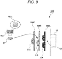
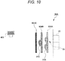
- FIGS. 9 and 10 are explanatory diagram illustrating a sixth configuration example of the platform hall. Further, FIG. 9 illustrates a state in which the car has stopped at the platform 51, and FIG. 10 illustrates a state in which the car stopped at the platform 51 has departed in FIG. 9 .
- a platform hall 80A according to the sixth configuration example only one platform 51 is provided as in the platform hall 80 according to the fourth configuration example. Further, the entrance of the platform hall 80A is arranged in front of the platform 51 as in the platform hall 80 according to the fourth configuration example.
- the call input display unit 403 and waiting position display units 604A, 604B, and 604C are installed.
- the waiting position display units 604A, 604B, and 604C are formed in front of the platform 51.
- the waiting position display units 604A, 604B, and 604C are arranged at intervals in the direction away from the front of the platform 51.
- the first waiting position display unit 604A is arranged at the position closest to the platform 51 among the waiting position display units 604A, 604B, and 604C.
- the third waiting position display unit 604C is arranged at the position farthest from the platform 51 among the waiting position display units 604A, 604B, and 604C.
- the second waiting position display unit 604B is arranged between the first waiting position display unit 604A and the third waiting position display unit 604C.
- the boarding group 21A on standby in the first waiting position display unit 604A gets on firstly among the boarding groups 21A, 21B, and 21C on standby in the waiting position display units 604A, 604B, and 604C.
- the boarding group 21B on standby in the second waiting position display unit 604B gets on secondly among the boarding groups 21A, 21B, and 21C on standby in the waiting position display units 604A, 604B, and 604C.
- the boarding group 21C on standby in the third waiting position display unit 604C gets on thirdly among the boarding groups 21A, 21B, and 21C on standby in the waiting position display units 604A, 604B, and 604C.
- the waiting position display units 604A, 604B, and 604C also serve as a boarding guidance display unit. Then, the waiting position display units 604A, 604B, and 604C change the displayed contents and blink or turn on the display based on the boarding guidance information from the group management control unit 101, so that the boarding groups 21A, 21B, and 21C are guided.
- the call input display unit 403 displays an identifier on a display unit 403a based on the boarding groups 21A, 21B, and 21C.
- the group management control unit 101 determines the boarding groups 21A, 21B, and 21C
- the order of getting on the car is also determined at the same time.
- the boarding groups 21A, 21B, and 21C guided by the call input display unit 403 may include not only those assigned to the third waiting position display unit 604C to be boarded last, but also the boarding groups 21A, 21B, and 21C on standby in the first waiting position display unit 604A and the second waiting position display unit 604B to be boarded first or second. That is, instead of having the passengers 21 board in the order which is input to the call input display unit 403, it is also allowed that passengers 21 input later to the call input display unit 403 to board first.
- the first waiting position display unit 604A closest to the platform 51 changes the displaying to board the first boarding group 21A on standby in the first waiting position display unit 604A, and guides the first boarding group 21A. Then, at the timing when the first boarding group 21A on standby in the first waiting position display unit 604A gets on the car and the platform door 15 is started to close, the displaying of the second waiting position display unit 604B and the third waiting position display unit 604C changes.
- the second waiting position display unit 604B and the third waiting position display unit 604C guide the second boarding group B and the third boarding group 21C on standby in the waiting position display units 604B and 604C to the waiting position display unit closest to the next previous platform 51.
- the first boarding group 21A which has stood by in the first waiting position display unit 604A in FIG. 9 , gets on the car. Then, the second boarding group 21B on standby in the second waiting position display unit 604B in FIG. 9 moves to the first waiting position display unit 604A, and the third boarding group 21C on standby in the third waiting position display unit 604C moves to the second waiting position display unit 604B.
- the passengers can easily determine the order of boarding based on the display contents of the waiting position display units 604A, 604B, and 604C, which also serve as the boarding guidance display unit. As a result, it is possible to prevent passengers from getting on the wrong car.
- the configuration example of the platform hall is not limited to the above-mentioned example, and for example, three or more platforms may be provided, and various other platform halls can be applied.
- FIGS. 3 , 4 , 11 to 14 an example of processing operation at the time of boarding guidance in the multi-car elevator system 1 having the above-described configuration will be described with reference to FIGS. 3 , 4 , 11 to 14 .
- the platform hall 50 according to the first configuration example described above will be used, but the platform halls 60, 70, 80, 80A, and 90 according to the second to sixth configuration examples, and a platform hall 80B according to a modification described below may be applied.
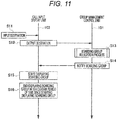
- FIG. 11 is a sequence diagram illustrating a notification process of the boarding group in the multi-car elevator system 1.
- the passenger 21 inputs a destination using the call input display unit 103 (Step S11).
- the destination input in Step S11 may be the stop floor where the car is stopped, or may be any place, purpose, or other various information in the building structure in which the multi-car elevator is installed.
- the call input display unit 103 outputs the destination information regarding the destination input by the passenger 21 to the group management control unit 101 (Step S12). Further, in the process of Step S12, the call input display unit 103 also outputs the call information for calling the car to the input platform hall to the group management control unit 101.
- the group management control unit 101 performs a boarding group allocation process based on the destination information, and determines the boarding groups 21A, 21B, and 21C (Step S13). That is, the group management control unit 101 assigns an appropriate boarding group from a plurality of boarding groups 21A, 21B, and 21C to the passenger. The boarding group allocation process in Step S13 will be described later. Then, the group management control unit 101 notifies the boarding groups 21A, 21B, and 21C determined in the boarding group allocation process to the call input display unit 103 (Step S14) .
- the call input display unit 103 starts displaying the boarding groups 21A, 21B, and 21C notified from the group management control unit 101 on the display unit (Step S15).
- the information displayed by the call input display unit 103 is, for example, an identifier for identifying a boarding group.
- Step S15 when a certain period of time has elapsed since the call input display unit 103 started displaying the boarding groups 21A, 21B, and 21C in the process of Step S15, the call input display unit 103 ends displaying the boarding groups 21A, 21B, and 21C (Step S16). As a result, the notification process of the boarding groups 21A, 21B, and 21C for the passenger 21 whose destination is input to the call input display unit 103 is completed.
- FIG. 12 is a flowchart illustrating the boarding group allocation process.
- the group management control unit 101 calculates a group allocation score for each boarding group based on the destination information received from the call input display unit 103 (Step S21). Next, the group management control unit 101 determines whether there is a boarding group whose group allocation score calculated in Step S21 is equal to or greater than a threshold (Step S22).
- Step S22 when the group management control unit 101 determines that there is a boarding group whose group allocation score is equal to or higher than the threshold (YES determination in Step S22), the group management control unit 101 assigns the boarding group having the maximum group allocation score as a boarding group for the input destination information (Step S23). Further, in the process of Step S23, when the group management control unit 101 determines that there is no boarding group whose group allocation score is equal to or higher than the threshold (NO determination in Step S22), the group management control unit 101 does not allocate the boarding group (Step S24). As a result, the boarding group allocation process is completed.
- the group allocation score Si is set to 0.
- the group allocation score Si of the boarding group in which the number ci of assigned passengers is equal to or more than the car capacity C becomes 0, and does not exceed the threshold "1" in the process of Step S22. Therefore, a boarding group having a group allocation score Si of 0 is not assigned to the destination information.
- the group allocation score Si of the boarding group in which the number ci of assigned passengers is less than the car capacity C is set to be larger as the number fi of destination types of passengers assigned to the passenger group becomes smaller.
- Step S23 it is possible to preferentially assign a boarding group having a small number of destination types of assigned passengers.
- the calculation method of the group allocation score is not limited to the above-mentioned example.
- the number of thresholds may be changed, or various coefficients such as boarding time and stop area may be used as the coefficients used in the calculation formula. Therefore, various other calculation methods can be applied as the calculation method of the group allocation score.
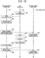
- FIG. 13 is a sequence diagram illustrating the boarding guidance display process.
- the car control unit 102 controls the drive unit and starts decelerating the car to stop (Step S31).
- the car control unit 102 transmits the movement information of the car to the group management control unit 101.
- the group management control unit 101 detects the deceleration of the car by receiving the movement information of the car from the car control unit 102 (Step S32). Then, the group management control unit 101 performs a departure group list output process (Step S33). The details of the departure group list output process will be described later. By the departure group list output process in the process of Step S33, the group management control unit 101 determines an appropriate boarding group to be boarded in the stopped car.
- the group management control unit 101 transmits the boarding guidance information for the platform, where the car to be boarded stops, to each of the boarding guidance display units 105A, 105B, and 105C. That is, the group management control unit 101 instructs each boarding guidance display units 105A, 105B, and 105C to start boarding guidance (Step S34).
- the boarding guidance display units 105A, 105B, and 105C start displaying the boarding guidance based on the boarding guidance information output from the group management control unit 101 (Step S35).
- the boarding guidance to the platforms 51A and 51B determined from the waiting position display units 104A, 104B, and 104C is displayed on the boarding guidance display units 105A, 105B, and 105C.
- Step S36 when the car arrives at the stop floor, the car control unit 102 stops the car (Step S36). Then, the car control unit 102 controls the opening/closing of the opening/closing door provided in the car, and opens the opening/closing door of the car (Step S37).
- the boarding group boarding this car moves to the platforms 51A and 51B according to the display contents of the boarding guidance display units 105A, 105B, and 105C, and gets on the car.
- the car control unit 102 controls the opening/closing of the opening/closing door and starts the door closing operation of the opening/closing door of the car (Step S38). Further, in the process of Step S38, the car control unit 102 transmits door closing start information to the group management control unit 101.
- the group management control unit 101 detects the door closing of the opening/closing door by receiving the door closing start information from the car control unit 102 (Step S39). Then, the group management control unit 101 transmits the boarding guidance information to each of the boarding guidance display units 105A, 105B, and 105C, and instructs the end of the boarding guidance (Step S40). When each of the boarding guidance display units 105A, 105B, and 105C receives the boarding guidance information regarding the end of the boarding guidance from the group management control unit 101, the boarding guidance display ends the displaying of the boarding guidance (Step S41). As a result, the boarding guidance process is completed.
- Step S33 a departure group list output process performed in the process of Step S33 will be described with reference to FIG. 14 .
- FIG. 14 is a flowchart illustrating the departure group list output process.
- the group management control unit 101 initializes the departure group list created and stored in the previous departure group list output process as an empty list (Step S51).
- This departure group list is a list for managing the boarding groups to be boarded in the car.
- the group management control unit 101 creates a departure group candidate list that is a candidate for the departure group list (Step S52).
- all boarding groups 21A, 21B, and 21C that is, combinations of all waiting position display units and all platforms are created as a departure group candidate list.
- the group management control unit 101 calculates a departure allocation score for each of the boarding groups 21A, 21B, and 21C for the arriving car (arrival car) from the departure group candidate list (Step S53).
- the value of the departure allocation score of the boarding group for more appropriate boarding on the arrival car is calculated to be higher than the departure allocation score of the other boarding groups.
- An example of the calculation method of the departure allocation score will be described later.
- Step S54 determines whether there is a boarding group whose departure allocation score calculated in Step S53 is equal to or greater than a threshold.
- the group management control unit 101 adds the boarding group having the maximum departure allocation score to the departure group list. Further, the group management control unit 101 deletes the boarding group added to the departure group list from the departure group candidate list (Step S55). Then, when the process of Step S55 is completed, the group management control unit 101 returns to the process of Step S53 again.
- Step S54 when the group management control unit 101 determines that there is no boarding group whose departure allocation score is equal to or higher than the threshold (NO determination in Step S54), the group management control unit 101 outputs the departure group list created by the above process (Step S56). As a result, the departure group list output process is completed.
- a departure allocation score Mi in a case where the waiting time of the boarding group is ti, the car capacity is C, the number of people who are assigned to the boarding group and standing by in the corresponding waiting position display unit is gi, the total number of people assigned to the arrival car is cj, and the threshold used in Step S54 is set to 1.
- the departure allocation score Mi is calculated by the following Expression 2.
- the departure allocation score Mi is set to 0.
- the waiting time ti of the boarding group is, for example, the waiting time of the passenger who is standing by first among the passengers of the boarding group.
- the departure allocation score Mi of the boarding group to which the number of people who cannot get on the arriving car is allocated is 0 and does not exceed the threshold of 1. Therefore, a boarding group with the departure allocation score Mi of 0 is not added to the departure group list.
- the value of the departure allocation score Mi becomes larger as the boarding group has a longer waiting time ti, as illustrated in Expression 2 above.
- the boarding group having a long waiting time ti can be preferentially added to the departure group list.
- the calculation method of the departure allocation score is not limited to the above-mentioned example.
- the number of thresholds may be changed, or various coefficients such as the destination information of the boarding group and the stop area may be used as the coefficients used in the calculation formula. Therefore, various other calculation methods can be applied as the calculation method of the departure allocation score.
- the passengers can easily determine a platform for getting on the car based on the display contents of the boarding guidance display units 105A, 105B, and 105C installed in each of the boarding groups 21A, 21B, and 21C. As a result, the burden of the passenger 21 on boarding decision can be reduced.
- FIG. 15 is an explanatory diagram illustrating a state in which the boarding taxiways intersect in a platform hall 60 in the second configuration example.
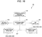
- FIG. 16 is a block diagram illustrating a schematic configuration of the multi-car elevator system according to the second embodiment.
- the platform hall 60 in which a plurality of platforms 51A and 51B are arranged in the second configuration example described above will be described.
- the third boarding guidance display unit 205C is already displayed to guide the passenger from the third waiting position display unit 204C to the first platform 51A.
- the display contents of the first boarding guidance display unit 205A and the second boarding guidance display unit 205B intersect with the already displayed third boarding guidance display unit 205C.
- a multi-car elevator system 1A according to the second embodiment is a system provided with a boarding allocation availability determination unit 110 in order to prevent the intersection of the boarding guidance display units described above. Therefore, the same reference numerals are given to the parts common to the multi-car elevator system 1 according to the first embodiment, and duplicate description will be omitted.
- the multi-car elevator system 1A includes the group management control unit 101, the car control unit 102, the call input display unit 103, the plurality of waiting position display units 104A, 104B, and 104C, and the plurality of boarding guidance display units 105A, 105B, and 105C. Further, the multi-car elevator system 1A is provided with the boarding allocation availability determination unit 110.
- the boarding allocation availability determination unit 110 is connected to the group management control unit 101 via the system bus 107.
- the boarding allocation availability determination unit 110 has boarding allocation availability condition data 1000 (see FIG. 17 ).
- the boarding allocation availability condition data 1000 is data in which the display contents of the boarding guidance display units 105A, 105B, and 105C and the availability condition for preventing the moving lines from intersecting are stored in the departure group list output process.
- FIG. 17 is a diagram illustrating an example of the boarding allocation availability condition data.
- the boarding allocation availability condition data 1000 corresponding to the platform hall 60 illustrated in FIGS. 5 and 15 is obtained. That is, an example is illustrated in which the boarding group is divided into three waiting positions and two platforms are installed.
- column 1001 in the boarding allocation availability condition data 1000 indicates a waiting position corresponding to each column
- row 1002 indicates a platform corresponding to each row. Then, in the cell where column 1001 and row 1002 intersect, whether the allocation is available is indicated based on the intersection of the moving lines. " ⁇ " in each cell indicates that allocation is available, and "x" indicates that allocation is not available.
- the first platform 51A can be assigned to the first waiting position, which is the waiting position of the first boarding group 21A. Further, since cell 1022 is "x", the second platform 51B cannot be assigned to the first waiting position. Since cell 1013 and cell 1014 are both " ⁇ ”, both the first platform 51A and the second platform 51B can be assigned to the second waiting position, which is the waiting position of the second boarding group 21B.
- the first platform 51A cannot be assigned to a third waiting position, which is the waiting position of the third boarding group 21C. Since cell 1016 is "o", the second platform 51B can be assigned to the third waiting position.
- the group management control unit 101 creates a departure group candidate list based on the boarding allocation availability condition data 1000. That is, the boarding allocation availability determination unit 110 extracts the cell of the boarding allocation availability condition data 1000 as "o", that is, the combinations of the boarding group and all the platforms that can be assigned. Then, the boarding allocation availability determination unit 110 creates the extracted combinations as a departure group candidate list. In addition, the boarding allocation availability determination unit 110 outputs the created departure group candidate list to the group management control unit 101.
- a departure group candidate list consisting of combinations in which the moving lines do not intersect can be created, and a departure group list in which the moving lines do not intersect can be output.
- the contents displayed on the boarding guidance display units 105A, 105B, and 105C do not intersect, so that each of the boarding groups 21A, 21B, and 21C can be smoothly guided.
- the multi-car elevator system according to the third embodiment is provided with the boarding allocation availability determination unit 110, similarly to the multi-car elevator system 1A according to the second embodiment. Further, the difference between the multi-car elevator system according to the third embodiment and the multi-car elevator system 1A according to the second embodiment is the contents of the boarding allocation availability condition data possessed by the boarding allocation availability determination unit 110. Therefore, here, the contents of the boarding allocation availability condition data will be described.
- the boarding allocation availability condition data is set so that the combinations that can be assigned to the boarding are not reduced while preventing the occurrence of intersecting the moving lines of the boarding guidance.
- Boarding allocation availability condition data 2000 illustrated in FIG. 18 is data indicating whether boarding allocation is possible for the first platform.
- column 2001 in the boarding allocation availability condition data 2000 illustrates the waiting position corresponding to each row and the state of boarding guidance from the waiting position to the first platform
- row 2002 indicates the waiting position corresponding to each column and the availability of boarding guidance from the waiting position to the platform.
- each intersecting cell indicates whether boarding guidance is possible. "o" in each cell indicates that allocation is available, and "x" indicates that allocation is not available.
- Row 2005 illustrates a case where the second waiting position, which is the waiting position of the second boarding group 21B, is assigned to the first platform 51A. Since cell 2011 is "o”, it is possible to assign from the first waiting position to the first platform 51A without intersecting the moving lines. Since the second waiting position has already been assigned to the first platform 51A, cell 2012 is "x”. And since cell 2013 is "o", it is possible to assign from the third waiting position to the first platform 51A without intersecting the moving lines.
- the availability of allocation at other waiting positions is indicated with respect to the allocation to the first platform 51A at one waiting position.
- the boarding allocation availability condition data 2000 it is possible to easily determine whether to allocate other waiting positions even for the allocation of platforms at a plurality of waiting positions.
- first waiting position which is the waiting position of the first boarding group 21A
- second platform 51B whether each waiting position can be assigned to the first platform 51A is illustrated in row 2004.
- second waiting position is assigned to the first platform 51A
- whether each waiting position can be assigned to the first platform 51A is illustrated in row 2005.
- the first waiting position is assigned to the second platform 51B and the second waiting position is assigned to the first platform 51A
- whether the other waiting position (third waiting position) is assigned is determined by the result that satisfies both row 2004 and row 2005. That is, the product of availability sets of the respective rows 2004 and 2005 may be taken. In this case, since "o" is not illustrated in any of the cells, the result that there is no other waiting position that can be assigned is obtained.
- Boarding allocation availability condition data 3000 illustrated in FIG. 19 is data indicating whether boarding allocation is possible for the second platform.
- column 3001 in the boarding allocation availability condition data 3000 indicates the waiting position corresponding to each row and the state of boarding guidance from the waiting position to the second platform
- row 3002 indicates the waiting position corresponding to each row and whether boarding guidance from the waiting position to the platform is possible.
- each intersecting cell indicates whether boarding guidance is possible.
- " ⁇ " in each cell indicates that allocation is available, and "x" indicates that allocation is not available.
- Row 3005 indicates the case where the second waiting position, which is the waiting position of the second boarding group 21B, is assigned to the first platform 51A. Since cell 3011 is "x”, it is not possible to assign from the first waiting position to the second platform 51B without intersecting the moving lines. Since the second waiting position has already been assigned to the first platform 51A, cell 3012 is "x”. Then, since cell 3013 is "o", it is possible to assign from the third waiting position to the second platform 51B without intersecting the moving lines.
- the boarding allocation availability condition data 3000 in FIG. 19 indicates whether allocation to the second platform 51B at one waiting position can be assigned at another waiting position.
- the boarding allocation availability condition data 3000 as in the case of the boarding allocation availability condition data 2000 illustrated in FIG. 18 described above, whether other waiting positions can be assigned to the allocation of the platform at a plurality of waiting positions can be easily obtained.
- first waiting position which is the waiting position of the first boarding group 21A
- second platform 51B whether each waiting position can be assigned to the second platform 51B is illustrated in line 3004.
- second waiting position is assigned to the first platform 51A
- whether each waiting position can be assigned to the second platform 51B is illustrated in row 3005.
- the first waiting position is assigned to the second platform 51B and the second waiting position is assigned to the first platform 51A
- whether the other waiting position (third waiting position) is assigned is determined by the result that satisfies both rows 3004 and 3005. That is, the product of sets of allocation availabilities of rows 3004 and 3005 may be taken respectively.
- the result is obtained that the other waiting position that can be assigned is the third waiting position.
- FIG. 20 is a flowchart illustrating a departure group list output process according to the third embodiment.
- the group management control unit 101 initializes the departure group list created and stored in the previous departure group list output process as an empty list (Step S71).
- the boarding allocation availability determination unit 110 creates a departure group candidate list based on the state of the boarding group allocation for each waiting position and the boarding allocation availability condition data 2000 and 3000 for each platform illustrated in FIGS. 18 and 19 . (Step S72). Then, the boarding allocation availability determination unit 110 outputs the created departure group candidate list to the group management control unit 101.
- the group management control unit 101 calculates the departure allocation score for each of the boarding groups 21A, 21B, and 21C for the arriving car (arrival car) from the departure group candidate list (Step S73).
- the value of the departure allocation score of the boarding group for which it is more appropriate to board the arrival car is calculated to be higher than the departure allocation score of the other boarding groups. For example, as illustrated in Expression 2 above, by giving a positive correlation to the waiting time ti, it is possible to increase the hit of the departure allocation score for the boarding group having a longer waiting time ti.
- Step S74 determines whether there is a boarding group whose departure allocation score calculated in Step S73 is equal to or higher than a threshold (Step S74).
- the group management control unit 101 adds the boarding group having the maximum departure allocation score to the departure group list (Step S75). Then, when the process of Step S75 is completed, the group management control unit 101 returns to the process of Step S73 again, and the boarding allocation availability determination unit 110 creates a departure group candidate list.
- Step S74 when the group management control unit 101 determines that there is no boarding group whose departure allocation score is equal to or higher than the threshold (NO determination in Step S74), the group management control unit 101 outputs the departure group list created in the above process (Step S76). As a result, the departure group list output process is completed.
- the boarding allocation availability determination unit 110 determines whether the allocation is possible using the boarding allocation availability condition data 2000 and 3000 illustrated in FIGS. 18 and 19 . As a result, even when the boarding guidance is performed for a plurality of waiting positions at the same time, it is possible to prevent the moving lines of passengers moving from each waiting position to the respective platforms 51A and 51B from intersecting. As a result, it is possible to reduce the possibility of smooth boarding and the possibility that passengers get in a wrong car.
- FIG. 21 is an explanatory diagram illustrating the configuration of the platform hall in the multi-car elevator system according to the modification.
- the difference between the multi-car elevator system according to this modification and the multi-car elevator system 1 according to the first embodiment is the configuration of the boarding guidance display unit. Therefore, the boarding guidance display unit will be described here, and the same reference numerals will be given to the parts common to the multi-car elevator system 1 according to the first embodiment, and duplicate description will be omitted.
- the platform hall 80B illustrated in FIG. 21 only one platform 51 is provided as in the platform hall 80 according to the fourth configuration example described above. As illustrated in FIG. 21 , the platform hall 80B is provided with the call input display unit 403, the waiting position display units 404A, 404B, and 404C, and boarding guidance display units 805A, 805B, and 805C. Since the configurations of the call input display unit 403 and the waiting position display units 404A, 404B, and 404C are the same as those of the platform hall 80 according to the fourth configuration example, the description thereof will be omitted.
- the boarding guidance display units 805A, 805B, and 805C are arranged on the wall surface provided with the platform door 15.
- the first boarding guidance display unit 805A is installed in front of the first waiting position display unit 404A. Therefore, the first boarding guidance display unit 805A is visibly installed from the first boarding group on standby in the first waiting position display unit 404A.
- the second boarding guidance display unit 805B is installed in front of the second waiting position display unit 404B so as to be visible from the second boarding group on standby in the second waiting position display unit 404B.
- the third boarding guidance display unit 805C is installed in front of the third waiting position display unit 404C so as to be visible from the third boarding group on standby in the third waiting position display unit 404C.
- the guidance information for the corresponding boarding group is displayed on the boarding guidance display units 805A, 805B, and 805C, respectively.
- various other display devices such as a liquid crystal display device and an organic EL display device are applied.
- the display screen of one display device may be divided into the boarding guidance display units 805A, 805B, and 805C.
- independent display devices may be provided as the boarding guidance display units 805A, 805B, and 805C.
- the car ascends and descends in the vertical direction as a multi-car elevator has been described, but the invention is not limited to this, and the car may move in a slope direction inclined from the horizontal direction and the vertical direction.
- the group management control unit may output the boarding guidance information, which indicates a platform where the car to be boarded stops, to a mobile terminal owned by the passenger who has input a destination in the call input display unit. Then, the passenger moves to the car or the platform to be boarded according to the boarding guidance information output to the mobile terminal. According to this configuration, it is not necessary to install a waiting position display unit or a boarding guidance display unit on which passengers stand by in the platform hall.
Landscapes
- Indicating And Signalling Devices For Elevators (AREA)
- Elevator Control (AREA)
Abstract
Description
- The present invention relates to a multi-car elevator system that controls a multi-car elevator in which a plurality of cars move in a moving path.
- In recent years, a multi-car elevator has been proposed in which a plurality of cars move in one moving path. In the multi-car elevator, the plurality of cars with different destinations stop at the same platform. Therefore, every time the car stops at the platform, the passenger needs to decide whether to get on the car.
- Further, as a technique for guiding the boarding, for example, there is one disclosed in PTL 1. In PTL 1, a car is assigned according to the destination floor input by the passenger, and when the assigned car is approaching the departure floor, an identification code is displayed in one of signs adjacent to the hoist way where the assigned car travels.
- PTL 1:
JP 2009-519876 T - However, in the technique described in PTL 1, every time the car arrives at the platform, the passenger needs to confirm whether the passenger should get on the arrived car by looking at the sign. As a result, when a plurality of cars arrive at the platform at the same time, the passenger must check the signs provided at each platform and make a decision in a short period of time, which increases the burden on the passenger's boarding decision.
- An object of the invention is to provide a multi-car elevator system that can reduce the burden of passengers' boarding decisions in consideration of the above problems.
- In order to solve the above problems and achieve the purpose, the multi-car elevator system is a multi-car elevator system that controls a multi-car elevator in which a plurality of cars move in the same moving path.
- The multi-car elevator system includes a call input display unit, a group management control unit, and a car control unit. The call input display unit is provided in the platform hall where the car stops, and the destination is input by the passenger. The group management control unit receives destination information regarding the passenger's destination transmitted from the call input display unit, and assigns a specific boarding group to the passenger from among a plurality of boarding groups based on the destination information. The car control unit controls the movement of the car, and transmits the movement information regarding the movement of the car to the group management control unit. In addition, the group management control unit calculates boarding guidance information, which is information regarding the car to be boarded by the passenger, for each of the plurality of boarding groups based on the movement information received from the car control unit, and outputs the information to the outside.
- According to the multi-car elevator system having the above configuration, it is possible to reduce the burden of passengers' decision on boarding.
-
- [
FIG. 1] FIG. 1 is a block diagram illustrating a schematic configuration of a multi-car elevator system according to a first embodiment. - [
FIG. 2] FIG. 2 is a schematic configuration diagram illustrating an example of a multi-car elevator controlled in the multi-car elevator system according to the first embodiment. - [
FIG. 3] FIG. 3 is an explanatory diagram illustrating a first configuration example of a platform hall of the multi-car elevator system according to the first embodiment. - [
FIG. 4] FIG. 4 is an explanatory diagram illustrating a first boarding guidance example of the multi-car elevator system according to the first embodiment. - [
FIG. 5] FIG. 5 is an explanatory diagram illustrating a second configuration example of the platform hall of the multi-car elevator system according to the first embodiment. - [
FIG. 6] FIG. 6 is an explanatory diagram illustrating a third configuration example of the platform hall of the multi-car elevator system according to the first embodiment. - [
FIG. 7] FIG. 7 is an explanatory diagram illustrating a fourth configuration example of the platform hall of the multi-car elevator system according to the first embodiment. - [
FIG. 8] FIG. 8 is an explanatory diagram illustrating a fifth configuration example of the platform hall of the multi-car elevator system according to the first embodiment. - [
FIG. 9] FIG. 9 is an explanatory diagram illustrating a sixth configuration example of the platform hall of the multi-car elevator system according to the first embodiment. - [
FIG. 10] FIG. 10 is an explanatory diagram illustrating the sixth configuration example of the platform hall of the multi-car elevator system according to the first embodiment. - [
FIG. 11] FIG. 11 is a sequence diagram illustrating a notification process of a boarding group in the multi-car elevator system according to the first embodiment. - [
FIG. 12] FIG. 12 is a flowchart illustrating a boarding group allocation process in the multi-car elevator system according to the first embodiment. - [
FIG. 13] FIG. 13 is a sequence diagram illustrating a boarding guidance display process in the multi-car elevator system according to the first embodiment. - [
FIG. 14] FIG. 14 is a flowchart illustrating a departure group list output process in the multi-car elevator system according to the first embodiment. - [
FIG. 15] FIG. 15 is an explanatory diagram illustrating a state in which boarding taxiways intersect in the platform hall in the second configuration example. - [
FIG. 16] FIG. 16 is a block diagram illustrating a schematic configuration of a multi-car elevator system according to a second embodiment. - [
FIG. 17] FIG. 17 is a diagram illustrating an example of boarding allocation availability condition data in the multi-car elevator system according to the second embodiment. - [
FIG. 18] FIG. 18 is a diagram illustrating an example of the boarding allocation availability condition data on a first platform in the multi-car elevator system according to a third embodiment. - [
FIG. 19] FIG. 19 is a diagram illustrating an example of the boarding allocation availability condition data on a second platform in the multi-car elevator system according to the third embodiment. - [
FIG. 20] FIG. 20 is a flowchart illustrating a departure group list output process in the multi-car elevator system according to the third embodiment. - [
FIG. 21] FIG. 21 is an explanatory diagram illustrating a configuration of a platform hall in a multi-car elevator system according to a modification. - Hereinafter, a multi-car elevator system according to embodiments will be described with reference to
FIGS. 1 to 21 . The common members in each drawing are designated by the same reference numerals. - First, the configuration of the multi-car elevator system according to a first embodiment (hereinafter, referred to as "this example") will be described with reference to
FIG. 1 . -
FIG. 1 is a block diagram illustrating a schematic configuration of the multi-car elevator system of this example. - A multi-car elevator system 1 illustrated in
FIG. 1 is a system that controls and guides boarding on the multi-car elevator 10 (seeFIG. 2 ) in which a plurality ofcars 11A to 11G move in one movingpath 5 formed in a building structure. As illustrated inFIG. 1 , the multi-car elevator system 1 includes a groupmanagement control unit 101, acar control unit 102, a callinput display unit 103, a plurality of waitingposition display units guidance display units - The group
management control unit 101, thecar control unit 102, the callinput display unit 103, and the plurality of boardingguidance display units system bus 107 so that information can be transmitted and received. Then, the groupmanagement control unit 101 controls the entire system. The groupmanagement control unit 101 has, for example, a CPU (Central Processing Unit), a RAM (Random Access Memory), and a ROM (Read Only Memory) . The RAM is used as the work area of the CPU, and the ROM stores programs executed by the CPU. - In addition, the group
management control unit 101 receives movement information of a car, opening/closing information of an opening/closing door from thecar control unit 102, and receives destination information of a passenger from the callinput display unit 103. The groupmanagement control unit 101 performs a boarding group allocation process on passengers to assign a specific boarding group from among a plurality of boarding groups based on the destination information received from the callinput display unit 103. - In addition, the group
management control unit 101 calculates a departure group list based on the movement information of the car from thecar control unit 102 and the boarding group information, and outputs boarding guidance information to each of the boardingguidance display units management control unit 101 will be described later. - The
car control unit 102 controls the movement of the plurality ofcars 11A to 11G (seeFIG. 2 ) moving along the moving path, and controls the opening and closing of the opening/closing doors provided in thecars 11A to 11G. Further, thecar control unit 102 transmits the movement information of thecars 11A to 11G and the opening/closing information of the opening/closing door to the groupmanagement control unit 101. - The call
input display unit 103, the waitingposition display units guidance display units FIG. 3 etc.) which is provided on each floor of the building structure for a passenger to board or alight. The callinput display unit 103 includes an input unit through which the passenger inputs a destination, and adisplay unit 103a (seeFIG. 3 ) that displays the assigned boarding group. - When the destination is input by the passenger, the call
input display unit 103 transmits the destination information and the call information for calling a car to the input platform hall to the groupmanagement control unit 101. Further, the callinput display unit 103 receives the boarding group information calculated by the groupmanagement control unit 101. This boarding group information is boarding group information for a passenger who has entered the destination. Then, the callinput display unit 103 displays an identifier for identifying the boarding group in the display unit based on the received boarding group information, and notifies the passenger who has input the destination of the boarding group. - The identifier for identifying the boarding group is indicated by, for example, any one or a plurality of combinations of a mechanism, characters, colors, patterns, and the like.
- The call
input display unit 103 is configured by, for example, a touch panel, a key input unit, a reading unit for reading tags and cards possessed by passengers, and the like. - Here, the boarding group is an individual, a group heading to the same floor, a group heading to the same zone by grouping multiple floors as one zone, a group determined by the multi-car elevator system 1, and the like.
- The waiting
position display units guidance display units position display units guidance display units - Next, an example of a multi-car elevator to which the above-mentioned multi-car elevator system 1 is applied will be described with reference to
FIG. 2 . -
FIG. 2 is a schematic configuration diagram illustrating an example of a multi-car elevator controlled by the multi-car elevator system 1 of this example. - As illustrated in
FIG. 2 , amulti-car elevator 10 includes a plurality ofcars cars 11A to 11F circulate in the movingpath 5 provided in the building structure. - Further, the moving
path 5 is provided with an ascendingpath 6 indicating a first moving path in which thecars 11A to 11F move upward and a descendingpath 7 indicating a second moving path in which thecars 11A to 11G move downward. Further, at the upper ends of the ascendingpath 6 and the descendingpath 7 in the vertical direction in the movingpath 5, a first reversingpath 8 is provided in which the movement of thecars 11A to 11F is reversed from ascending to descending. Further, at the lower ends of the ascendingpath 6 and the descendingpath 7 in the vertical direction in the movingpath 5, a second reversingpath 9 is provided in which the movement of thecars 11A to 11F is reversed from descending to ascending. - Then, the plurality of
cars 11A to 11F are driven by the drive unit and circulate in the ascendingpath 6, the descendingpath 7, the first reversingpath 8, and the second reversingpath 9 in the movingpath 5. - As the
multi-car elevator 10, the multi-car elevator in which the plurality ofcars 11A to 11F circulate and move has been described, but the invention is not limited to this. For example, it can be applied to a multi-car elevator in which a plurality of cars can move up and down the moving path in both directions. - As a driving method for the
cars 11A to 11F of themulti-car elevator 10, there may be used a driving method provided with a hoisting machine and a driving method in which a linear drive unit is provided and an induced current flows to the main rope connected to thecars 11A to 11F to generate a driving force (thrust) in the main rope itself. It can also be applied to self-propelled multi-car elevators with drive units on thecars 11A to 11F. - Further, the number of cars provided in the
multi-car elevator 10 is not limited to 6, and the number of cars may be 5 or less, or 7 or more. - In addition, on the stop floor where
cars 11A to 11F stop in the building structure, there is aplatform hall 50 where apassenger 21 gets on and off. - Next, an example of boarding guidance in the multi-car elevator system 1 of this example will be described with reference to
FIGS. 3 to 9 . The dotted lines illustrated inFIGS. 3 to 9 indicate a state in which the boarding guidance display unit is turned off. - First, with reference to
FIG. 3 , a first configuration example of the platform hall will be described with reference toFIGS. 3 and4 . -
FIG. 3 is an explanatory diagram illustrating a first configuration example of the platform hall. - In the
platform hall 50 illustrated inFIG. 3 , there are provided twoplatforms passenger 21 gets on and off thecars 11A to 11G. Thefirst platform 51A and thesecond platform 51B are located opposite each other in theplatform hall 50. Thefirst platform 51A and thesecond platform 51B each are provided with entrances for thepassenger 21 to get on and off thecars 11A to 11G. Further, at this entrance, aplatform door 15 is installed so that it can be opened and closed. - In addition, the
passenger 21 comes in and out theplatform hall 50 from the side of thefirst platform 51A and thesecond platform 51B, which are orthogonal to the direction in which thefirst platform 51A and thesecond platform 51B face each other. Therefore, the entrances of theplatform hall 50 are arranged on the sides of thefirst platform 51A and thesecond platform 51B. - Further, in the
platform hall 50, the callinput display unit 103, the plurality of waitingposition display units guidance display units input display unit 103 is installed at the entrance of theplatform hall 50. The waitingposition display units guidance display units input display unit 103 and thefirst platform 51A and thesecond platform 51B. - When the destination is input by the
passenger 21, the callinput display unit 103 transmits the destination information and the call information to the groupmanagement control unit 101. Then, the callinput display unit 103 receives the boarding group information calculated by the groupmanagement control unit 101, and displays the identifier on the display unit based on the boarding group information. As a result, thepassenger 21 comes to know that it is better to stand at which of the waitingposition display units position display units input display unit 103. - The waiting
position display units passenger 21 who has input the destination to the callinput display unit 103 to wait for thecars 11A to 11G. The waitingposition display units platform hall 50 for each of the assignedboarding groups position display unit 104A corresponds to thefirst boarding group 21A, the second waitingposition display unit 104B corresponds to thesecond boarding group 21B, and the third waitingposition display unit 104C corresponds to thethird boarding group 21C. - The waiting
position display units first platform 51A and thesecond platform 51B face each other. The waitingposition display units position display units - Although an example in which the waiting
position display units boarding groups position display units position display units - The boarding
guidance display units platform hall 50. The boardingguidance display units position display units guidance display unit 105A is visibly arranged with respect to thefirst boarding group 21A on standby in the first waitingposition display unit 104A. The second boardingguidance display unit 105B is visibly arranged with respect to thesecond boarding group 21B on standby in the second waitingposition display unit 104B, and the third boardingguidance display unit 105C is visibly arranged with respect to thethird boarding group 21C on standby in the third waitingposition display unit 104C. - The boarding
guidance display units platform hall 50. The boardingguidance display units management control unit 101. Then, the boardingguidance display units corresponding boarding groups platforms - Next, a first boarding guidance example will be described with reference to
FIG. 4 . -
FIG. 4 is an explanatory diagram illustrating a first boarding guidance example. - As illustrated in
FIG. 4 , when the car stops or approaches thefirst platform 51A and thesecond platform 51B, the groupmanagement control unit 101 transmits the boarding guidance information to the boardingguidance display units guidance display units management control unit 101, and guide thecorresponding boarding groups platforms - In the example illustrated in
FIG. 4 , thefirst boarding group 21A is assigned to thefirst platform 51A, and thesecond boarding group 21B and thethird boarding group 21C are assigned to thesecond platform 51B. As illustrated inFIG. 4 , the first boardingguidance display unit 105A is turned on or blinks from the head of the first waitingposition display unit 104A to thefirst platform 51A. The second boardingguidance display unit 105B is turned on or blinks from the head of the second waitingposition display unit 104B to thesecond platform 51B, and the third boardingguidance display unit 105C is turned on or blinks from the head of the third waitingposition display unit 104C to thesecond platform 51B. - Therefore, the passenger of the
first boarding group 21A comes to know that it is better to get on the car stopped at thefirst platform 51A by the first boardingguidance display unit 105A. In addition, the passengers of thesecond boarding group 21B and the passengers of thethird boarding group 21C may come to know that it is better to get on the car stopped at thesecond platform 51B by the second boardingguidance display unit 105B and the third boardingguidance display unit 105C. - As described above, according to the multi-car elevator system 1 of this example, the
passenger 21 can easily determine a car to get on based on the display contents of the boardingguidance display units position display units passenger 21 on boarding decision can be reduced. - Next, a second boarding guidance example will be described with reference to
FIG. 5 . -
FIG. 5 is an explanatory diagram illustrating a second configuration example of the platform hall.FIG. 5 illustrates a state in which the cars are stopped at theplatforms platform hall 50 according to the first configuration example are designated by the same reference numerals, and duplicate description will be omitted. - In the
platform hall 60 according to the second configuration example illustrated inFIG. 5 , twoplatforms platform hall 50 of the first configuration example. Thefirst platform 51A and thesecond platform 51B are arranged side by side. - Further, in the
platform hall 60, a callinput display unit 203, a plurality of waitingposition display units guidance display units guidance display units position display units first platform 51A and thesecond platform 51B. - Further, in the example illustrated in
FIG. 5 , thefirst boarding group 21A is assigned to thefirst platform 51A, and thethird boarding group 21C is assigned to thesecond platform 51B. Thesecond boarding group 21B is in a standby state without getting on the car arriving at thefirst platform 51A and thesecond platform 51B this time. - The first boarding
guidance display unit 205A is turned on or blinks from the first waitingposition display unit 204A to thefirst platform 51A, and the third boardingguidance display unit 205C is turned on or blinks from the third waitingposition display unit 204C to thesecond platform 51B. Then, the second boardingguidance display unit 205B is turned off. - As a result, since the second boarding
guidance display unit 205B is turned off, thesecond boarding group 21B can know that it is better not to get on the car arriving at thefirst platform 51A and thesecond platform 51B this time. On the other hand, thefirst boarding group 21A can know that it is better to get on the car stopped at thefirst platform 51A based on the display contents of the first boardingguidance display unit 205A, and thethird boarding group 21C can know that it is better to get on the car stopped at thesecond platform 51B based on the display contents of the third boardingguidance display unit 205C. - In this way, the passenger can easily determine a car to be boarded based on the display contents of the boarding
guidance display units 205A to 205B. - Next, a third boarding guidance example will be described with reference to
FIG. 6 . -
FIG. 6 is an explanatory diagram illustrating a third configuration example of the platform hall.FIG. 6 illustrates a state in which the car is stopped at theplatforms platform hall 50 according to the first configuration example are designated by the same reference numerals, and duplicate description will be omitted. - In a
platform hall 70 according to the third configuration example illustrated inFIG. 6 , twoplatforms platform hall 50 according to the first configuration example. Thefirst platform 51A and thesecond platform 51B are arranged side by side in the same manner as theplatform hall 60 in the second configuration example. - In addition, the
passenger 21 enters and exits theplatform hall 70 from the direction facing thefirst platform 51A and thesecond platform 51B. Therefore, the entrance of theplatform hall 70 is located in front of thefirst platform 51A and thesecond platform 51B. - Further, in the
platform hall 70, a callinput display unit 303, waitingposition display units guidance display units input display unit 303 is arranged at a position facing thefirst platform 51A and thesecond platform 51B, which are the entrances and exits of theplatform hall 70. - The waiting
position display units first platform 51A and thesecond platform 51B in parallel with the direction facing thefirst platform 51A and thesecond platform 51B. Further, the waitingposition display units first platform 51A and thesecond platform 51B are aligned. The boardingguidance display units position display units first platform 51A and thesecond platform 51B. - In the example illustrated in
FIG. 6 , thefirst boarding group 21A and thesecond boarding group 21B are assigned to thefirst platform 51A, and thethird boarding group 21C is assigned to thesecond platform 51B. Therefore, the first boardingguidance display unit 305A is turned on or blinks from the first waitingposition display unit 304A to thefirst platform 51A, and the second boardingguidance display unit 305B is turned on or blinks from the second waitingposition display unit 304B to thefirst platform 51A. The third boardingguidance display unit 305C is turned on or blinking from the third waitingposition display unit 304C to thesecond platform 51B. - As a result, the passenger can easily determine the car to be boarded based on the display contents of the boarding
guidance display units 305A to 305C. - Next, a fourth boarding guidance example will be described with reference to
FIG. 7 . -
FIG. 7 is an explanatory diagram illustrating a fourth configuration example of the platform hall.FIG. 7 illustrates a state in which the car is stopped at aplatform 51. The portions common to theplatform hall 50 according to the first configuration example are designated by the same reference numerals, and duplicate description will be omitted. - In a
platform hall 80 according to the fourth configuration example illustrated inFIG. 7 , only oneplatform 51 is provided. Further, the entrance of theplatform hall 80 is arranged in front of theplatform 51 as in theplatform hall 70 according to the third configuration example. - In the platform hall 80 a call
input display unit 403, waitingposition display units guidance display units input display unit 403 is arranged at a position facing theplatform 51, which is the entrance of theplatform hall 80. The waitingposition display units platform 51 in parallel with the direction facing theplatform 51. - The boarding
guidance display units position display units platform 51. The boardingguidance display units position display units platform 51. - In the example illustrated in
FIG. 7 , thefirst boarding group 21A and thethird boarding group 21C are assigned to get on the car arriving at theplatform 51 this time. Then, thesecond boarding group 21B is in a standby state without boarding the car that has arrived at theplatform 51 this time. - Therefore, the first boarding guidance display unit 405 and the third boarding
guidance display unit 405C are turned on or blinking, and the second boardingguidance display unit 405B is turned off. As a result, the passengers of thefirst boarding group 21A and thethird boarding group 21C know that it is better to get on the arrived car based on the display contents of the first boardingguidance display unit 405A and the third boardingguidance display unit 405C. Then, the passenger of thesecond boarding group 21B knows that it is not better to get on the arrived car this time based on the display contents of the second boardingguidance display unit 405B. - As a result, the passenger can easily determine the car to be boarded based on the display contents of the boarding
guidance display units 405A to 405C. - Next, a fifth boarding guidance example will be described with reference to
FIG. 8 . -
FIG. 8 is an explanatory diagram illustrating a fifth configuration example of the platform hall.FIG. 8 illustrates a state in which the cars are stopped at theplatforms platform hall 50 according to the first configuration example are designated by the same reference numerals, and duplicate description will be omitted. - As illustrated in
FIG. 8 , in aplatform hall 90 according to the fifth configuration example, thefirst platform 51A and thesecond platform 51B are arranged side by side in the same manner as theplatform halls platform hall 90 is arranged in front of thefirst platform 51A and thesecond platform 51B, as in theplatform hall 70 according to the third configuration example. - In the
platform hall 80, a callinput display unit 503, waitingposition display units guidance display units - The first waiting
position display unit 504A, the second waitingposition display unit 504B, and the third waitingposition display unit 504C are formed in front of thefirst platform 51A. The fourth waitingposition display unit 504D, the fifth waitingposition display unit 504E, and the sixth waitingposition display unit 504F are formed in front of thesecond platform 51B. - The first boarding
guidance display unit 505A extends from the head of the first waitingposition display unit 504A to thefirst platform 51A, the second boardingguidance display unit 505B extends from the head of the second waitingposition display unit 504B to thefirst platform 51A, and the third boardingguidance display unit 505C extends from the head of the third waitingposition display unit 504C to thefirst platform 51A. - In addition, the fourth boarding
guidance display unit 505D extends from the head of the fourth waitingposition display unit 504D to thesecond platform 51B, the fifth boardingguidance display unit 505E extends from the head of the fifth waitingposition display unit 504E to thesecond platform 51B, and the sixth boardingguidance display unit 505F extends from the head of the sixth waitingposition display unit 504F to thesecond platform 51B. - As described above, in the
platform hall 90 according to the fifth configuration example, the waitingposition display units 504A to 504F and the boardingguidance display units 505A to 505F are provided for each of theplatforms - Further, when the destination is input by the
passenger 21, the callinput display unit 503 displays an identifier based on the boarding group. In the fifth configuration example, when the groupmanagement control unit 101 determines the boarding group, the platform for getting on the car is also determined at the same time. That is, when thepassengers 21 are assigned to thefirst boarding group 21A, thesecond boarding group 21B, and thethird boarding group 21C, the groupmanagement control unit 101 assigns the passengers to board from thefirst platform 51A at the same time. Then, when thepassengers 21 are assigned to thefourth boarding group 21D, thefifth boarding group 21E, and thesixth boarding group 21F, the groupmanagement control unit 101 assigns the passengers to board from thesecond platform 51B at the same time. - In the example illustrated in
FIG. 8 , the first boarding group and thethird boarding group 21C assigned to thefirst platform 51A are assigned to get on the car that has arrived at thefirst platform 51A this time. Then, thesecond boarding group 21B assigned to thefirst platform 51A is in a standby state without getting on the car that has arrived at thefirst platform 51A this time. - In addition, the
fifth boarding group 21E assigned to thesecond platform 51B is assigned to get on the car that has arrived at thesecond platform 51B this time. Then, thefourth boarding group 21D and thesixth boarding group 21F assigned to thesecond platform 51B are in a standby state without getting on the car that has arrived at thesecond platform 51B this time. - Therefore, among the boarding
guidance display units 505A to 505C arranged at thefirst platform 51A, the first boardingguidance display unit 505A and the third boardingguidance display unit 505C are turned on or blink, and the second boardingguidance display unit 505B is turned off. In addition, among the boardingguidance display units 505D to 505F arranged at thesecond platform 51B, the fifth boardingguidance display unit 505E is turned on or blinks, and the fourth boardingguidance display unit 505D and the sixth boardingguidance display unit 505F are turned on. - As a result, the passenger can easily determine the car to be boarded based on the display contents of the boarding
guidance display units 505A to 505F. - Next, a sixth boarding guidance example of the platform hall will be described with reference to
FIGS. 9 and10 .FIGS. 9 and10 are explanatory diagram illustrating a sixth configuration example of the platform hall. Further,FIG. 9 illustrates a state in which the car has stopped at theplatform 51, andFIG. 10 illustrates a state in which the car stopped at theplatform 51 has departed inFIG. 9 . - As illustrated in
FIG. 9 , in aplatform hall 80A according to the sixth configuration example, only oneplatform 51 is provided as in theplatform hall 80 according to the fourth configuration example. Further, the entrance of theplatform hall 80A is arranged in front of theplatform 51 as in theplatform hall 80 according to the fourth configuration example. - In the
platform hall 80A the callinput display unit 403 and waitingposition display units - The waiting
position display units platform 51. The waitingposition display units platform 51. The first waitingposition display unit 604A is arranged at the position closest to theplatform 51 among the waitingposition display units position display unit 604C is arranged at the position farthest from theplatform 51 among the waitingposition display units position display unit 604B is arranged between the first waitingposition display unit 604A and the third waitingposition display unit 604C. - The
boarding group 21A on standby in the first waitingposition display unit 604A gets on firstly among theboarding groups position display units boarding group 21B on standby in the second waitingposition display unit 604B gets on secondly among theboarding groups position display units boarding group 21C on standby in the third waitingposition display unit 604C gets on thirdly among theboarding groups position display units - The waiting
position display units position display units management control unit 101, so that theboarding groups - When the destination is input by the
passenger 21, the callinput display unit 403 displays an identifier on adisplay unit 403a based on theboarding groups management control unit 101 determines theboarding groups boarding groups input display unit 403 may include not only those assigned to the third waitingposition display unit 604C to be boarded last, but also theboarding groups position display unit 604A and the second waitingposition display unit 604B to be boarded first or second. That is, instead of having thepassengers 21 board in the order which is input to the callinput display unit 403, it is also allowed thatpassengers 21 input later to the callinput display unit 403 to board first. - In addition, when the car approaches or stops at the
platform 51, the first waitingposition display unit 604A closest to theplatform 51 changes the displaying to board thefirst boarding group 21A on standby in the first waitingposition display unit 604A, and guides thefirst boarding group 21A. Then, at the timing when thefirst boarding group 21A on standby in the first waitingposition display unit 604A gets on the car and theplatform door 15 is started to close, the displaying of the second waitingposition display unit 604B and the third waitingposition display unit 604C changes. That is, the second waitingposition display unit 604B and the third waitingposition display unit 604C guide the second boarding group B and thethird boarding group 21C on standby in the waitingposition display units previous platform 51. - As a result, as illustrated in
FIG. 10 , thefirst boarding group 21A, which has stood by in the first waitingposition display unit 604A inFIG. 9 , gets on the car. Then, thesecond boarding group 21B on standby in the second waitingposition display unit 604B inFIG. 9 moves to the first waitingposition display unit 604A, and thethird boarding group 21C on standby in the third waitingposition display unit 604C moves to the second waitingposition display unit 604B. - As a result, the passengers can easily determine the order of boarding based on the display contents of the waiting
position display units - The configuration example of the platform hall is not limited to the above-mentioned example, and for example, three or more platforms may be provided, and various other platform halls can be applied.
- Next, an example of processing operation at the time of boarding guidance in the multi-car elevator system 1 having the above-described configuration will be described with reference to
FIGS. 3 ,4 ,11 to 14 . In the following description, theplatform hall 50 according to the first configuration example described above will be used, but theplatform halls platform hall 80B according to a modification described below may be applied. -
FIG. 11 is a sequence diagram illustrating a notification process of the boarding group in the multi-car elevator system 1. - First, the notification process of the boarding group will be described with reference to
FIGS. 3 and11 . - The
passenger 21 inputs a destination using the call input display unit 103 (Step S11). The destination input in Step S11 may be the stop floor where the car is stopped, or may be any place, purpose, or other various information in the building structure in which the multi-car elevator is installed. - Next, the call
input display unit 103 outputs the destination information regarding the destination input by thepassenger 21 to the group management control unit 101 (Step S12). Further, in the process of Step S12, the callinput display unit 103 also outputs the call information for calling the car to the input platform hall to the groupmanagement control unit 101. - Next, the group
management control unit 101 performs a boarding group allocation process based on the destination information, and determines theboarding groups management control unit 101 assigns an appropriate boarding group from a plurality ofboarding groups management control unit 101 notifies theboarding groups - Next, the call
input display unit 103 starts displaying theboarding groups management control unit 101 on the display unit (Step S15). As described above, the information displayed by the callinput display unit 103 is, for example, an identifier for identifying a boarding group. - Next, when a certain period of time has elapsed since the call
input display unit 103 started displaying theboarding groups input display unit 103 ends displaying theboarding groups boarding groups passenger 21 whose destination is input to the callinput display unit 103 is completed. - Next, a boarding group allocation process performed in the process of
Step 13 will be described with reference toFIG. 12 . -
FIG. 12 is a flowchart illustrating the boarding group allocation process. - As illustrated in
FIG. 12 , the groupmanagement control unit 101 calculates a group allocation score for each boarding group based on the destination information received from the call input display unit 103 (Step S21). Next, the groupmanagement control unit 101 determines whether there is a boarding group whose group allocation score calculated in Step S21 is equal to or greater than a threshold (Step S22). - In the process of Step S22, when the group
management control unit 101 determines that there is a boarding group whose group allocation score is equal to or higher than the threshold (YES determination in Step S22), the groupmanagement control unit 101 assigns the boarding group having the maximum group allocation score as a boarding group for the input destination information (Step S23). Further, in the process of Step S23, when the groupmanagement control unit 101 determines that there is no boarding group whose group allocation score is equal to or higher than the threshold (NO determination in Step S22), the groupmanagement control unit 101 does not allocate the boarding group (Step S24). As a result, the boarding group allocation process is completed. - Next, an example of the calculation method of the group allocation score Si performed in the process of Step S21 will be described.
- The description will be given about the group allocation score Si for each group in a case where the car capacity is C, the number of assigned passengers assigned to the boarding group is ci, the number of destination types of the assigned passengers is fi, and the threshold used in Step S22 is 1. When ci < C, that is, when the number of assigned passengers ci has not reached the car capacity C, the group allocation score Si is calculated by the following Expression 1.

- Further, when ci ≥ C, that is, when the number of assigned passengers ci has reached the car capacity C, the group allocation score Si is set to 0.
- According to the group allocation score Si calculated by the above method, the group allocation score Si of the boarding group in which the number ci of assigned passengers is equal to or more than the car capacity C becomes 0, and does not exceed the threshold "1" in the process of Step S22. Therefore, a boarding group having a group allocation score Si of 0 is not assigned to the destination information.
- On the other hand, as illustrated in Expression 1 above, the group allocation score Si of the boarding group in which the number ci of assigned passengers is less than the car capacity C is set to be larger as the number fi of destination types of passengers assigned to the passenger group becomes smaller. As a result, in the process of Step S23, it is possible to preferentially assign a boarding group having a small number of destination types of assigned passengers.
- The calculation method of the group allocation score is not limited to the above-mentioned example. For example, the number of thresholds may be changed, or various coefficients such as boarding time and stop area may be used as the coefficients used in the calculation formula. Therefore, various other calculation methods can be applied as the calculation method of the group allocation score.
- Next, a boarding guidance display process will be described with reference to
FIGS. 4 and13 . -
FIG. 13 is a sequence diagram illustrating the boarding guidance display process. - First, the
car control unit 102 controls the drive unit and starts decelerating the car to stop (Step S31). In the process of Step S31, thecar control unit 102 transmits the movement information of the car to the groupmanagement control unit 101. - Next, the group
management control unit 101 detects the deceleration of the car by receiving the movement information of the car from the car control unit 102 (Step S32). Then, the groupmanagement control unit 101 performs a departure group list output process (Step S33). The details of the departure group list output process will be described later. By the departure group list output process in the process of Step S33, the groupmanagement control unit 101 determines an appropriate boarding group to be boarded in the stopped car. - Next, based on the departure group list output in the process of Step S33, the group
management control unit 101 transmits the boarding guidance information for the platform, where the car to be boarded stops, to each of the boardingguidance display units management control unit 101 instructs each boardingguidance display units - Next, the boarding
guidance display units FIG. 4 , the boarding guidance to theplatforms position display units guidance display units - Next, when the car arrives at the stop floor, the
car control unit 102 stops the car (Step S36). Then, thecar control unit 102 controls the opening/closing of the opening/closing door provided in the car, and opens the opening/closing door of the car (Step S37). The boarding group boarding this car moves to theplatforms guidance display units car control unit 102 controls the opening/closing of the opening/closing door and starts the door closing operation of the opening/closing door of the car (Step S38). Further, in the process of Step S38, thecar control unit 102 transmits door closing start information to the groupmanagement control unit 101. - Next, the group
management control unit 101 detects the door closing of the opening/closing door by receiving the door closing start information from the car control unit 102 (Step S39). Then, the groupmanagement control unit 101 transmits the boarding guidance information to each of the boardingguidance display units guidance display units management control unit 101, the boarding guidance display ends the displaying of the boarding guidance (Step S41). As a result, the boarding guidance process is completed. - Next, a departure group list output process performed in the process of Step S33 will be described with reference to
FIG. 14 . -
FIG. 14 is a flowchart illustrating the departure group list output process. - First, the group
management control unit 101 initializes the departure group list created and stored in the previous departure group list output process as an empty list (Step S51). This departure group list is a list for managing the boarding groups to be boarded in the car. - Next, the group
management control unit 101 creates a departure group candidate list that is a candidate for the departure group list (Step S52). In the multi-car elevator system 1 according to the first embodiment, allboarding groups - Next, the group
management control unit 101 calculates a departure allocation score for each of theboarding groups - Next, the group
management control unit 101 determines whether there is a boarding group whose departure allocation score calculated in Step S53 is equal to or greater than a threshold (Step S54). In the process of Step S54, when the groupmanagement control unit 101 determines that there is a boarding group whose departure allocation score is equal to or higher than the threshold (YES determination in Step S54), the groupmanagement control unit 101 adds the boarding group having the maximum departure allocation score to the departure group list. Further, the groupmanagement control unit 101 deletes the boarding group added to the departure group list from the departure group candidate list (Step S55). Then, when the process of Step S55 is completed, the groupmanagement control unit 101 returns to the process of Step S53 again. - Further, in the process of Step S54, when the group
management control unit 101 determines that there is no boarding group whose departure allocation score is equal to or higher than the threshold (NO determination in Step S54), the groupmanagement control unit 101 outputs the departure group list created by the above process (Step S56). As a result, the departure group list output process is completed. - Next, an example of the calculation method of a departure allocation score Mi of the boarding group performed in the process of Step S53 will be described.
- The description will be given about a departure allocation score Mi in a case where the waiting time of the boarding group is ti, the car capacity is C, the number of people who are assigned to the boarding group and standing by in the corresponding waiting position display unit is gi, the total number of people assigned to the arrival car is cj, and the threshold used in Step S54 is set to 1. First, when cj + gi < C, the departure allocation score Mi is calculated by the following
Expression 2.
- Also, when cj + gi ≥ C, the departure allocation score Mi is set to 0. The waiting time ti of the boarding group is, for example, the waiting time of the passenger who is standing by first among the passengers of the boarding group.
- According to the departure allocation score Mi calculated by the above method, the departure allocation score Mi of the boarding group to which the number of people who cannot get on the arriving car is allocated is 0 and does not exceed the threshold of 1. Therefore, a boarding group with the departure allocation score Mi of 0 is not added to the departure group list.
- On the other hand, if the passengers get on the arriving car but still fit within the car capacity C, the value of the departure allocation score Mi becomes larger as the boarding group has a longer waiting time ti, as illustrated in
Expression 2 above. As a result, in the process of Step S55, the boarding group having a long waiting time ti can be preferentially added to the departure group list. - The calculation method of the departure allocation score is not limited to the above-mentioned example. For example, the number of thresholds may be changed, or various coefficients such as the destination information of the boarding group and the stop area may be used as the coefficients used in the calculation formula. Therefore, various other calculation methods can be applied as the calculation method of the departure allocation score.
- In this way, according to the multi-car elevator system 1 of this example, the passengers can easily determine a platform for getting on the car based on the display contents of the boarding
guidance display units boarding groups passenger 21 on boarding decision can be reduced. - Next, the multi-car elevator system according to the second embodiment will be described with reference to
FIGS. 15 to 17 . -
FIG. 15 is an explanatory diagram illustrating a state in which the boarding taxiways intersect in aplatform hall 60 in the second configuration example.FIG. 16 is a block diagram illustrating a schematic configuration of the multi-car elevator system according to the second embodiment. - In the example illustrated in
FIG. 15 , theplatform hall 60 in which a plurality ofplatforms FIG. 15 , the third boardingguidance display unit 205C is already displayed to guide the passenger from the third waitingposition display unit 204C to thefirst platform 51A. At this time, when thefirst boarding group 21A and thesecond boarding group 21B are assigned to thesecond platform 51B, the display contents of the first boardingguidance display unit 205A and the second boardingguidance display unit 205B intersect with the already displayed third boardingguidance display unit 205C. - In this way, when the boarding
guidance display units - A
multi-car elevator system 1A according to the second embodiment is a system provided with a boarding allocationavailability determination unit 110 in order to prevent the intersection of the boarding guidance display units described above. Therefore, the same reference numerals are given to the parts common to the multi-car elevator system 1 according to the first embodiment, and duplicate description will be omitted. - As illustrated in
FIG. 16 , themulti-car elevator system 1A includes the groupmanagement control unit 101, thecar control unit 102, the callinput display unit 103, the plurality of waitingposition display units guidance display units multi-car elevator system 1A is provided with the boarding allocationavailability determination unit 110. - The boarding allocation
availability determination unit 110 is connected to the groupmanagement control unit 101 via thesystem bus 107. The boarding allocationavailability determination unit 110 has boarding allocation availability condition data 1000 (seeFIG. 17 ). The boarding allocationavailability condition data 1000 is data in which the display contents of the boardingguidance display units -
FIG. 17 is a diagram illustrating an example of the boarding allocation availability condition data. - In the example illustrated in
FIG. 17 , the boarding allocationavailability condition data 1000 corresponding to theplatform hall 60 illustrated inFIGS. 5 and15 is obtained. That is, an example is illustrated in which the boarding group is divided into three waiting positions and two platforms are installed. - As illustrated in
FIG. 17 ,column 1001 in the boarding allocationavailability condition data 1000 indicates a waiting position corresponding to each column, androw 1002 indicates a platform corresponding to each row. Then, in the cell wherecolumn 1001 androw 1002 intersect, whether the allocation is available is indicated based on the intersection of the moving lines. "○" in each cell indicates that allocation is available, and "x" indicates that allocation is not available. - Specifically, since
cell 1011 is "o", thefirst platform 51A can be assigned to the first waiting position, which is the waiting position of thefirst boarding group 21A. Further, since cell 1022 is "x", thesecond platform 51B cannot be assigned to the first waiting position. Sincecell 1013 andcell 1014 are both "○", both thefirst platform 51A and thesecond platform 51B can be assigned to the second waiting position, which is the waiting position of thesecond boarding group 21B. - Further, since
cell 1015 is "x", thefirst platform 51A cannot be assigned to a third waiting position, which is the waiting position of thethird boarding group 21C. Sincecell 1016 is "o", thesecond platform 51B can be assigned to the third waiting position. - In the
multi-car elevator system 1A according to the second embodiment, in a departure group candidate list creation process of Step S52 illustrated inFIG. 14 , the groupmanagement control unit 101 creates a departure group candidate list based on the boarding allocationavailability condition data 1000. That is, the boarding allocationavailability determination unit 110 extracts the cell of the boarding allocationavailability condition data 1000 as "o", that is, the combinations of the boarding group and all the platforms that can be assigned. Then, the boarding allocationavailability determination unit 110 creates the extracted combinations as a departure group candidate list. In addition, the boarding allocationavailability determination unit 110 outputs the created departure group candidate list to the groupmanagement control unit 101. - As a result, a departure group candidate list consisting of combinations in which the moving lines do not intersect can be created, and a departure group list in which the moving lines do not intersect can be output. As a result, according to the
multi-car elevator system 1A of the second embodiment, the contents displayed on the boardingguidance display units boarding groups - Next, the multi-car elevator system according to a third embodiment will be described with reference to
FIGS. 18 to 20 . - The multi-car elevator system according to the third embodiment is provided with the boarding allocation
availability determination unit 110, similarly to themulti-car elevator system 1A according to the second embodiment. Further, the difference between the multi-car elevator system according to the third embodiment and themulti-car elevator system 1A according to the second embodiment is the contents of the boarding allocation availability condition data possessed by the boarding allocationavailability determination unit 110. Therefore, here, the contents of the boarding allocation availability condition data will be described. - In the multi-car elevator system according to the third embodiment, the boarding allocation availability condition data is set so that the combinations that can be assigned to the boarding are not reduced while preventing the occurrence of intersecting the moving lines of the boarding guidance.
- Next, an example of the boarding allocation availability condition data will be described with reference to
FIGS. 18 and19 . - Boarding allocation
availability condition data 2000 illustrated inFIG. 18 is data indicating whether boarding allocation is possible for the first platform. As illustrated inFIG. 18 ,column 2001 in the boarding allocationavailability condition data 2000 illustrates the waiting position corresponding to each row and the state of boarding guidance from the waiting position to the first platform, androw 2002 indicates the waiting position corresponding to each column and the availability of boarding guidance from the waiting position to the platform. Then, each intersecting cell indicates whether boarding guidance is possible. "o" in each cell indicates that allocation is available, and "x" indicates that allocation is not available. - A specific example will be described with reference to
row 2005.Row 2005 illustrates a case where the second waiting position, which is the waiting position of thesecond boarding group 21B, is assigned to thefirst platform 51A. Sincecell 2011 is "o", it is possible to assign from the first waiting position to thefirst platform 51A without intersecting the moving lines. Since the second waiting position has already been assigned to thefirst platform 51A,cell 2012 is "x". And sincecell 2013 is "o", it is possible to assign from the third waiting position to thefirst platform 51A without intersecting the moving lines. - In the boarding allocation
availability condition data 2000 illustrated inFIG. 18 , the availability of allocation at other waiting positions is indicated with respect to the allocation to thefirst platform 51A at one waiting position. However, in the boarding allocationavailability condition data 2000, it is possible to easily determine whether to allocate other waiting positions even for the allocation of platforms at a plurality of waiting positions. - For example, if the first waiting position, which is the waiting position of the
first boarding group 21A, is assigned to thesecond platform 51B, whether each waiting position can be assigned to thefirst platform 51A is illustrated inrow 2004. As described above, when the second waiting position is assigned to thefirst platform 51A, whether each waiting position can be assigned to thefirst platform 51A is illustrated inrow 2005. - Here, when the first waiting position is assigned to the
second platform 51B and the second waiting position is assigned to thefirst platform 51A, whether the other waiting position (third waiting position) is assigned is determined by the result that satisfies bothrow 2004 androw 2005. That is, the product of availability sets of therespective rows - Boarding allocation
availability condition data 3000 illustrated inFIG. 19 is data indicating whether boarding allocation is possible for the second platform. As illustrated inFIG. 19 ,column 3001 in the boarding allocationavailability condition data 3000 indicates the waiting position corresponding to each row and the state of boarding guidance from the waiting position to the second platform, androw 3002 indicates the waiting position corresponding to each row and whether boarding guidance from the waiting position to the platform is possible. Then, each intersecting cell indicates whether boarding guidance is possible. "○" in each cell indicates that allocation is available, and "x" indicates that allocation is not available. - A specific example will be described with reference to
row 3005.Row 3005 indicates the case where the second waiting position, which is the waiting position of thesecond boarding group 21B, is assigned to thefirst platform 51A. Sincecell 3011 is "x", it is not possible to assign from the first waiting position to thesecond platform 51B without intersecting the moving lines. Since the second waiting position has already been assigned to thefirst platform 51A,cell 3012 is "x". Then, sincecell 3013 is "o", it is possible to assign from the third waiting position to thesecond platform 51B without intersecting the moving lines. - Further, the boarding allocation
availability condition data 3000 inFIG. 19 indicates whether allocation to thesecond platform 51B at one waiting position can be assigned at another waiting position. However, in the boarding allocationavailability condition data 3000, as in the case of the boarding allocationavailability condition data 2000 illustrated inFIG. 18 described above, whether other waiting positions can be assigned to the allocation of the platform at a plurality of waiting positions can be easily obtained. - For example, if the first waiting position, which is the waiting position of the
first boarding group 21A, is assigned to thesecond platform 51B, whether each waiting position can be assigned to thesecond platform 51B is illustrated inline 3004. As described above, when the second waiting position is assigned to thefirst platform 51A, whether each waiting position can be assigned to thesecond platform 51B is illustrated inrow 3005. - Here, when the first waiting position is assigned to the
second platform 51B and the second waiting position is assigned to thefirst platform 51A, whether the other waiting position (third waiting position) is assigned is determined by the result that satisfies bothrows rows - Next, the departure group list output process in the multi-car elevator system according to the third embodiment having the above-described configuration will be described with reference to
FIG. 20 . -
FIG. 20 is a flowchart illustrating a departure group list output process according to the third embodiment. - First, the group
management control unit 101 initializes the departure group list created and stored in the previous departure group list output process as an empty list (Step S71). Next, the boarding allocationavailability determination unit 110 creates a departure group candidate list based on the state of the boarding group allocation for each waiting position and the boarding allocationavailability condition data FIGS. 18 and19 . (Step S72). Then, the boarding allocationavailability determination unit 110 outputs the created departure group candidate list to the groupmanagement control unit 101. - Next, the group
management control unit 101 calculates the departure allocation score for each of theboarding groups Expression 2 above, by giving a positive correlation to the waiting time ti, it is possible to increase the hit of the departure allocation score for the boarding group having a longer waiting time ti. - Next, the group
management control unit 101 determines whether there is a boarding group whose departure allocation score calculated in Step S73 is equal to or higher than a threshold (Step S74). In the process of Step S74, when the groupmanagement control unit 101 determines that there is a boarding group whose departure allocation score is equal to or higher than the threshold (YES determination in Step S74), the groupmanagement control unit 101 adds the boarding group having the maximum departure allocation score to the departure group list (Step S75). Then, when the process of Step S75 is completed, the groupmanagement control unit 101 returns to the process of Step S73 again, and the boarding allocationavailability determination unit 110 creates a departure group candidate list. - Further, in the process of Step S74, when the group
management control unit 101 determines that there is no boarding group whose departure allocation score is equal to or higher than the threshold (NO determination in Step S74), the groupmanagement control unit 101 outputs the departure group list created in the above process (Step S76). As a result, the departure group list output process is completed. - As described above, according to the multi-car elevator system according to the third embodiment, the boarding allocation
availability determination unit 110 determines whether the allocation is possible using the boarding allocationavailability condition data FIGS. 18 and19 . As a result, even when the boarding guidance is performed for a plurality of waiting positions at the same time, it is possible to prevent the moving lines of passengers moving from each waiting position to therespective platforms - Next, a modification of the multi-car elevator system will be described with reference to
FIG. 21 . -
FIG. 21 is an explanatory diagram illustrating the configuration of the platform hall in the multi-car elevator system according to the modification. - The difference between the multi-car elevator system according to this modification and the multi-car elevator system 1 according to the first embodiment is the configuration of the boarding guidance display unit. Therefore, the boarding guidance display unit will be described here, and the same reference numerals will be given to the parts common to the multi-car elevator system 1 according to the first embodiment, and duplicate description will be omitted.
- In the
platform hall 80B illustrated inFIG. 21 , only oneplatform 51 is provided as in theplatform hall 80 according to the fourth configuration example described above. As illustrated inFIG. 21 , theplatform hall 80B is provided with the callinput display unit 403, the waitingposition display units guidance display units input display unit 403 and the waitingposition display units platform hall 80 according to the fourth configuration example, the description thereof will be omitted. - The boarding
guidance display units platform door 15. The first boardingguidance display unit 805A is installed in front of the first waitingposition display unit 404A. Therefore, the first boardingguidance display unit 805A is visibly installed from the first boarding group on standby in the first waitingposition display unit 404A. The second boardingguidance display unit 805B is installed in front of the second waitingposition display unit 404B so as to be visible from the second boarding group on standby in the second waitingposition display unit 404B. The third boardingguidance display unit 805C is installed in front of the third waitingposition display unit 404C so as to be visible from the third boarding group on standby in the third waitingposition display unit 404C. - The guidance information for the corresponding boarding group is displayed on the boarding
guidance display units guidance display units guidance display units guidance display units guidance display units - Since other configurations are the same as those of the boarding
guidance display units guidance display units - The invention is not limited to the embodiments described above and illustrated in the drawings, and various modifications can be made without departing from the gist of the invention described in the claims.
- In the above-described embodiment, an example in which the car ascends and descends in the vertical direction as a multi-car elevator has been described, but the invention is not limited to this, and the car may move in a slope direction inclined from the horizontal direction and the vertical direction.
- Further, in the above-described embodiment, an example in which a boarding guidance display unit for displaying boarding guidance is provided in the platform hall as a multi-car elevator system has been described, but the invention is not limited to this. For example, when the car arrives or approaches, the group management control unit may output the boarding guidance information, which indicates a platform where the car to be boarded stops, to a mobile terminal owned by the passenger who has input a destination in the call input display unit. Then, the passenger moves to the car or the platform to be boarded according to the boarding guidance information output to the mobile terminal. According to this configuration, it is not necessary to install a waiting position display unit or a boarding guidance display unit on which passengers stand by in the platform hall.
- Although words such as "parallel" and "orthogonal" have been used in the present specification, these do not mean only strict "parallel" and "orthogonal", but include "parallel" and "orthogonal". Further, it may be in a "substantially parallel" or "substantially orthogonal" state within a range in which the function can be exhibited. Reference Signs List
-
- 1, 1A
- multi-car elevator system
- 5
- moving path
- 10
- multi-car elevator
- 11A, 11B, 11C, 11D, 11E, 11F
- car
- 15
- platform door
- 21
- passenger
- 21A
- first boarding group
- 21B
- second boarding group
- 21C
- third boarding group
- 50
- platform hall
- 51A
- first platform
- 51B
- second platform
- 101
- group management control unit
- 102
- car control unit
- 103
- call input display unit
- 104A
- first waiting position display unit
- 104B.
- second waiting position display unit
- 104C
- third waiting position display unit
- 105A
- first boarding guidance display unit
- 105B
- second boarding guidance display unit
- 105C
- third boarding guidance display unit
- 107
- system bus
- 110
- boarding allocation availability determination unit
Claims (6)
- A multi-car elevator system for controlling a multi-car elevator in which a plurality of cars move in the same moving path, comprising:a call input display unit that is provided in a platform hall where the car stops and receives a destination from a passenger;a group management control unit that receives destination information, which is transmitted from the call input display unit, regarding the destination of the passenger, and assigns the passenger to a specific boarding group from among a plurality of boarding groups based on the destination information; anda car control unit that controls moving of the car and transmits movement information regarding the moving of the car to the group management control unit,wherein the group management control unit calculates boarding guidance information, which is information regarding the car to be boarded by the passenger, for each of the plurality of boarding groups based on the movement information received from the car control unit, and outputs the boarding guidance information to an outside.
- The multi-car elevator system according to claim 1, comprising:a boarding guidance display unit that receives the boarding guidance information output by the group management control unit, and displays boarding guidance to guide the passenger,wherein the boarding guidance display unit is provided for each of the plurality of boarding groups, and installed to be visible from a corresponding boarding group.
- The multi-car elevator system according to claim 1,
wherein the platform hall is provided with a plurality of platforms where the car stops, and
wherein the boarding guidance information output by the group management control unit also includes information regarding a platform where the car to be boarded stops among the plurality of platforms. - The multi-car elevator system according to claim 3,
wherein the platform hall is provided with a plurality of waiting position display units, where the passenger stands by, for each of the plurality of boarding groups,
the multi-car elevator system comprising:
a boarding allocation availability determination unit that determines whether to board from the platform based on moving lines of movement from the plurality of waiting position display units to the plurality of platforms,
wherein the group management control unit calculates the boarding guidance information based on information determined by the boarding allocation availability determination unit. - The multi-car elevator system according to claim 4,
wherein the boarding allocation availability determination unit outputs combinations of the plurality of waiting position display units and the plurality of platforms, where the moving lines of movement from the plurality of waiting position display units and the platform of platforms do not intersect, as a departure group candidate list to the group management control unit, and
wherein the group management control unit calculates the boarding guidance information from the departure group candidate list. - The multi-car elevator system according to claim 1,
wherein the group management control unit calculates the boarding guidance information based on the movement information when the car stops or approaches the platform, and outputs the boarding guidance information.
Applications Claiming Priority (2)
| Application Number | Priority Date | Filing Date | Title |
|---|---|---|---|
| JP2018144511A JP7073221B2 (en) | 2018-07-31 | 2018-07-31 | Multicar elevator system |
| PCT/JP2019/016805 WO2020026540A1 (en) | 2018-07-31 | 2019-04-19 | Multi-car elevator system |
Publications (3)
| Publication Number | Publication Date |
|---|---|
| EP3831758A1 true EP3831758A1 (en) | 2021-06-09 |
| EP3831758A4 EP3831758A4 (en) | 2022-04-13 |
| EP3831758B1 EP3831758B1 (en) | 2024-02-21 |
Family
ID=69231571
Family Applications (1)
| Application Number | Title | Priority Date | Filing Date |
|---|---|---|---|
| EP19844665.0A Active EP3831758B1 (en) | 2018-07-31 | 2019-04-19 | Multi-car elevator system |
Country Status (4)
| Country | Link |
|---|---|
| EP (1) | EP3831758B1 (en) |
| JP (1) | JP7073221B2 (en) |
| CN (1) | CN112449630B (en) |
| WO (1) | WO2020026540A1 (en) |
Families Citing this family (2)
| Publication number | Priority date | Publication date | Assignee | Title |
|---|---|---|---|---|
| WO2022084571A1 (en) * | 2020-10-20 | 2022-04-28 | Kone Corporation | Guidance solution |
| CN116457296A (en) * | 2020-12-31 | 2023-07-18 | 通力股份公司 | Method and apparatus for an elevator system |
Family Cites Families (13)
| Publication number | Priority date | Publication date | Assignee | Title |
|---|---|---|---|---|
| JPH07277609A (en) * | 1994-04-11 | 1995-10-24 | Hitachi Ltd | Elevator system controller |
| JP3841401B2 (en) * | 2001-09-26 | 2006-11-01 | 株式会社東芝 | Campus guidance device, server device, and program |
| BRPI0520787A2 (en) | 2005-12-15 | 2009-10-06 | Otis Elevator Co | elevator system and method of operation thereof |
| FI118963B (en) * | 2006-10-12 | 2008-05-30 | Kone Corp | wayfinding |
| JP4388546B2 (en) * | 2006-12-28 | 2009-12-24 | 株式会社日立製作所 | Elevator group management system and service elevator guidance display method |
| JP5054450B2 (en) * | 2007-07-12 | 2012-10-24 | 株式会社日立製作所 | Circulating multi-car elevator monitoring and control system |
| CN102159484B (en) * | 2008-09-19 | 2014-02-26 | 三菱电机株式会社 | Elevator group management system |
| JP5273567B2 (en) * | 2010-04-20 | 2013-08-28 | フジテック株式会社 | Destination floor registration device |
| JP2013049510A (en) * | 2011-08-30 | 2013-03-14 | Toshiba Elevator Co Ltd | Group-control system of elevator |
| DE112012007232T5 (en) * | 2012-12-17 | 2015-09-24 | Mitsubishi Electric Corporation | Elevator display control device |
| JP6249409B2 (en) * | 2014-05-15 | 2017-12-20 | 三菱電機株式会社 | Elevator guide device and elevator guide method |
| JP6492888B2 (en) * | 2015-03-31 | 2019-04-03 | フジテック株式会社 | Elevator group management system |
| US10155639B2 (en) * | 2016-06-08 | 2018-12-18 | Otis Elevator Company | Elevator notice system |
-
2018
- 2018-07-31 JP JP2018144511A patent/JP7073221B2/en active Active
-
2019
- 2019-04-19 WO PCT/JP2019/016805 patent/WO2020026540A1/en not_active Ceased
- 2019-04-19 CN CN201980048474.4A patent/CN112449630B/en active Active
- 2019-04-19 EP EP19844665.0A patent/EP3831758B1/en active Active
Also Published As
| Publication number | Publication date |
|---|---|
| CN112449630B (en) | 2022-05-27 |
| EP3831758A4 (en) | 2022-04-13 |
| JP2020019618A (en) | 2020-02-06 |
| EP3831758B1 (en) | 2024-02-21 |
| CN112449630A (en) | 2021-03-05 |
| WO2020026540A1 (en) | 2020-02-06 |
| JP7073221B2 (en) | 2022-05-23 |
Similar Documents
| Publication | Publication Date | Title |
|---|---|---|
| EP2891620B1 (en) | Elevator group supervision controlling apparatus | |
| EP1509471B1 (en) | Method and apparatus for controlling an elevator system | |
| CN107200245B (en) | Passenger guidance system for multi-car elevator | |
| CN106276438B (en) | A kind of elevator scheduling method | |
| KR100990547B1 (en) | Elevator control system | |
| CN101356107B (en) | Information display in elevator car | |
| TWI394704B (en) | Display device and communication method for an elevator system | |
| KR101039082B1 (en) | Identifying Call-Related Elevator Cars Elevator System and How It Works | |
| US7392883B2 (en) | Elevator group control system | |
| JP6584031B1 (en) | elevator | |
| CN110775744B (en) | Multi-car elevator and multi-car elevator control method | |
| EP3831758B1 (en) | Multi-car elevator system | |
| CN107235390A (en) | Elevator group management controller | |
| JP4739848B2 (en) | Group management elevator control system | |
| CN101137567A (en) | Method for transporting people in a building | |
| JP6068690B1 (en) | Elevator system | |
| EP3835246B1 (en) | Improved passenger interface for shuttle elevator system | |
| JP6576014B1 (en) | Elevator system | |
| JP6624159B2 (en) | Elevator group management system | |
| JP7182938B2 (en) | Multi-car elevator system and building structure | |
| JP7136256B1 (en) | elevator controller | |
| JP6936776B2 (en) | Multi-car elevator device and control method of multi-car elevator device | |
| HK1234382B (en) | Elevator system |
Legal Events
| Date | Code | Title | Description |
|---|---|---|---|
| STAA | Information on the status of an ep patent application or granted ep patent |
Free format text: STATUS: THE INTERNATIONAL PUBLICATION HAS BEEN MADE |
|
| PUAI | Public reference made under article 153(3) epc to a published international application that has entered the european phase |
Free format text: ORIGINAL CODE: 0009012 |
|
| STAA | Information on the status of an ep patent application or granted ep patent |
Free format text: STATUS: REQUEST FOR EXAMINATION WAS MADE |
|
| 17P | Request for examination filed |
Effective date: 20210301 |
|
| AK | Designated contracting states |
Kind code of ref document: A1 Designated state(s): AL AT BE BG CH CY CZ DE DK EE ES FI FR GB GR HR HU IE IS IT LI LT LU LV MC MK MT NL NO PL PT RO RS SE SI SK SM TR |
|
| DAV | Request for validation of the european patent (deleted) | ||
| DAX | Request for extension of the european patent (deleted) | ||
| A4 | Supplementary search report drawn up and despatched |
Effective date: 20220315 |
|
| RIC1 | Information provided on ipc code assigned before grant |
Ipc: B66B 1/46 20060101ALI20220309BHEP Ipc: B66B 1/24 20060101ALI20220309BHEP Ipc: B66B 3/00 20060101AFI20220309BHEP |
|
| GRAP | Despatch of communication of intention to grant a patent |
Free format text: ORIGINAL CODE: EPIDOSNIGR1 |
|
| STAA | Information on the status of an ep patent application or granted ep patent |
Free format text: STATUS: GRANT OF PATENT IS INTENDED |
|
| INTG | Intention to grant announced |
Effective date: 20230904 |
|
| GRAS | Grant fee paid |
Free format text: ORIGINAL CODE: EPIDOSNIGR3 |
|
| GRAA | (expected) grant |
Free format text: ORIGINAL CODE: 0009210 |
|
| STAA | Information on the status of an ep patent application or granted ep patent |
Free format text: STATUS: THE PATENT HAS BEEN GRANTED |
|
| AK | Designated contracting states |
Kind code of ref document: B1 Designated state(s): AL AT BE BG CH CY CZ DE DK EE ES FI FR GB GR HR HU IE IS IT LI LT LU LV MC MK MT NL NO PL PT RO RS SE SI SK SM TR |
|
| REG | Reference to a national code |
Ref country code: GB Ref legal event code: FG4D |
|
| REG | Reference to a national code |
Ref country code: CH Ref legal event code: EP |
|
| REG | Reference to a national code |
Ref country code: DE Ref legal event code: R096 Ref document number: 602019047049 Country of ref document: DE |
|
| REG | Reference to a national code |
Ref country code: IE Ref legal event code: FG4D |
|
| REG | Reference to a national code |
Ref country code: LT Ref legal event code: MG9D |
|
| REG | Reference to a national code |
Ref country code: NL Ref legal event code: MP Effective date: 20240221 |
|
| PG25 | Lapsed in a contracting state [announced via postgrant information from national office to epo] |
Ref country code: IS Free format text: LAPSE BECAUSE OF FAILURE TO SUBMIT A TRANSLATION OF THE DESCRIPTION OR TO PAY THE FEE WITHIN THE PRESCRIBED TIME-LIMIT Effective date: 20240621 |
|
| PG25 | Lapsed in a contracting state [announced via postgrant information from national office to epo] |
Ref country code: LT Free format text: LAPSE BECAUSE OF FAILURE TO SUBMIT A TRANSLATION OF THE DESCRIPTION OR TO PAY THE FEE WITHIN THE PRESCRIBED TIME-LIMIT Effective date: 20240221 |
|
| PG25 | Lapsed in a contracting state [announced via postgrant information from national office to epo] |
Ref country code: GR Free format text: LAPSE BECAUSE OF FAILURE TO SUBMIT A TRANSLATION OF THE DESCRIPTION OR TO PAY THE FEE WITHIN THE PRESCRIBED TIME-LIMIT Effective date: 20240522 |
|
| REG | Reference to a national code |
Ref country code: AT Ref legal event code: MK05 Ref document number: 1658984 Country of ref document: AT Kind code of ref document: T Effective date: 20240221 |
|
| PG25 | Lapsed in a contracting state [announced via postgrant information from national office to epo] |
Ref country code: RS Free format text: LAPSE BECAUSE OF FAILURE TO SUBMIT A TRANSLATION OF THE DESCRIPTION OR TO PAY THE FEE WITHIN THE PRESCRIBED TIME-LIMIT Effective date: 20240521 Ref country code: NL Free format text: LAPSE BECAUSE OF FAILURE TO SUBMIT A TRANSLATION OF THE DESCRIPTION OR TO PAY THE FEE WITHIN THE PRESCRIBED TIME-LIMIT Effective date: 20240221 Ref country code: HR Free format text: LAPSE BECAUSE OF FAILURE TO SUBMIT A TRANSLATION OF THE DESCRIPTION OR TO PAY THE FEE WITHIN THE PRESCRIBED TIME-LIMIT Effective date: 20240221 |
|
| PG25 | Lapsed in a contracting state [announced via postgrant information from national office to epo] |
Ref country code: ES Free format text: LAPSE BECAUSE OF FAILURE TO SUBMIT A TRANSLATION OF THE DESCRIPTION OR TO PAY THE FEE WITHIN THE PRESCRIBED TIME-LIMIT Effective date: 20240221 |
|
| PG25 | Lapsed in a contracting state [announced via postgrant information from national office to epo] |
Ref country code: AT Free format text: LAPSE BECAUSE OF FAILURE TO SUBMIT A TRANSLATION OF THE DESCRIPTION OR TO PAY THE FEE WITHIN THE PRESCRIBED TIME-LIMIT Effective date: 20240221 |
|
| PG25 | Lapsed in a contracting state [announced via postgrant information from national office to epo] |
Ref country code: RS Free format text: LAPSE BECAUSE OF FAILURE TO SUBMIT A TRANSLATION OF THE DESCRIPTION OR TO PAY THE FEE WITHIN THE PRESCRIBED TIME-LIMIT Effective date: 20240521 Ref country code: NO Free format text: LAPSE BECAUSE OF FAILURE TO SUBMIT A TRANSLATION OF THE DESCRIPTION OR TO PAY THE FEE WITHIN THE PRESCRIBED TIME-LIMIT Effective date: 20240521 Ref country code: NL Free format text: LAPSE BECAUSE OF FAILURE TO SUBMIT A TRANSLATION OF THE DESCRIPTION OR TO PAY THE FEE WITHIN THE PRESCRIBED TIME-LIMIT Effective date: 20240221 Ref country code: LT Free format text: LAPSE BECAUSE OF FAILURE TO SUBMIT A TRANSLATION OF THE DESCRIPTION OR TO PAY THE FEE WITHIN THE PRESCRIBED TIME-LIMIT Effective date: 20240221 Ref country code: IS Free format text: LAPSE BECAUSE OF FAILURE TO SUBMIT A TRANSLATION OF THE DESCRIPTION OR TO PAY THE FEE WITHIN THE PRESCRIBED TIME-LIMIT Effective date: 20240621 Ref country code: HR Free format text: LAPSE BECAUSE OF FAILURE TO SUBMIT A TRANSLATION OF THE DESCRIPTION OR TO PAY THE FEE WITHIN THE PRESCRIBED TIME-LIMIT Effective date: 20240221 Ref country code: GR Free format text: LAPSE BECAUSE OF FAILURE TO SUBMIT A TRANSLATION OF THE DESCRIPTION OR TO PAY THE FEE WITHIN THE PRESCRIBED TIME-LIMIT Effective date: 20240522 Ref country code: FI Free format text: LAPSE BECAUSE OF FAILURE TO SUBMIT A TRANSLATION OF THE DESCRIPTION OR TO PAY THE FEE WITHIN THE PRESCRIBED TIME-LIMIT Effective date: 20240221 Ref country code: ES Free format text: LAPSE BECAUSE OF FAILURE TO SUBMIT A TRANSLATION OF THE DESCRIPTION OR TO PAY THE FEE WITHIN THE PRESCRIBED TIME-LIMIT Effective date: 20240221 Ref country code: BG Free format text: LAPSE BECAUSE OF FAILURE TO SUBMIT A TRANSLATION OF THE DESCRIPTION OR TO PAY THE FEE WITHIN THE PRESCRIBED TIME-LIMIT Effective date: 20240221 Ref country code: AT Free format text: LAPSE BECAUSE OF FAILURE TO SUBMIT A TRANSLATION OF THE DESCRIPTION OR TO PAY THE FEE WITHIN THE PRESCRIBED TIME-LIMIT Effective date: 20240221 |
|
| PG25 | Lapsed in a contracting state [announced via postgrant information from national office to epo] |
Ref country code: PL Free format text: LAPSE BECAUSE OF FAILURE TO SUBMIT A TRANSLATION OF THE DESCRIPTION OR TO PAY THE FEE WITHIN THE PRESCRIBED TIME-LIMIT Effective date: 20240221 Ref country code: PT Free format text: LAPSE BECAUSE OF FAILURE TO SUBMIT A TRANSLATION OF THE DESCRIPTION OR TO PAY THE FEE WITHIN THE PRESCRIBED TIME-LIMIT Effective date: 20240621 |
|
| PG25 | Lapsed in a contracting state [announced via postgrant information from national office to epo] |
Ref country code: SE Free format text: LAPSE BECAUSE OF FAILURE TO SUBMIT A TRANSLATION OF THE DESCRIPTION OR TO PAY THE FEE WITHIN THE PRESCRIBED TIME-LIMIT Effective date: 20240221 Ref country code: PT Free format text: LAPSE BECAUSE OF FAILURE TO SUBMIT A TRANSLATION OF THE DESCRIPTION OR TO PAY THE FEE WITHIN THE PRESCRIBED TIME-LIMIT Effective date: 20240621 Ref country code: PL Free format text: LAPSE BECAUSE OF FAILURE TO SUBMIT A TRANSLATION OF THE DESCRIPTION OR TO PAY THE FEE WITHIN THE PRESCRIBED TIME-LIMIT Effective date: 20240221 Ref country code: LV Free format text: LAPSE BECAUSE OF FAILURE TO SUBMIT A TRANSLATION OF THE DESCRIPTION OR TO PAY THE FEE WITHIN THE PRESCRIBED TIME-LIMIT Effective date: 20240221 |
|
| PG25 | Lapsed in a contracting state [announced via postgrant information from national office to epo] |
Ref country code: DK Free format text: LAPSE BECAUSE OF FAILURE TO SUBMIT A TRANSLATION OF THE DESCRIPTION OR TO PAY THE FEE WITHIN THE PRESCRIBED TIME-LIMIT Effective date: 20240221 |
|
| PG25 | Lapsed in a contracting state [announced via postgrant information from national office to epo] |
Ref country code: SM Free format text: LAPSE BECAUSE OF FAILURE TO SUBMIT A TRANSLATION OF THE DESCRIPTION OR TO PAY THE FEE WITHIN THE PRESCRIBED TIME-LIMIT Effective date: 20240221 |
|
| PG25 | Lapsed in a contracting state [announced via postgrant information from national office to epo] |
Ref country code: CZ Free format text: LAPSE BECAUSE OF FAILURE TO SUBMIT A TRANSLATION OF THE DESCRIPTION OR TO PAY THE FEE WITHIN THE PRESCRIBED TIME-LIMIT Effective date: 20240221 Ref country code: EE Free format text: LAPSE BECAUSE OF FAILURE TO SUBMIT A TRANSLATION OF THE DESCRIPTION OR TO PAY THE FEE WITHIN THE PRESCRIBED TIME-LIMIT Effective date: 20240221 |
|
| PG25 | Lapsed in a contracting state [announced via postgrant information from national office to epo] |
Ref country code: SK Free format text: LAPSE BECAUSE OF FAILURE TO SUBMIT A TRANSLATION OF THE DESCRIPTION OR TO PAY THE FEE WITHIN THE PRESCRIBED TIME-LIMIT Effective date: 20240221 |
|
| PG25 | Lapsed in a contracting state [announced via postgrant information from national office to epo] |
Ref country code: SM Free format text: LAPSE BECAUSE OF FAILURE TO SUBMIT A TRANSLATION OF THE DESCRIPTION OR TO PAY THE FEE WITHIN THE PRESCRIBED TIME-LIMIT Effective date: 20240221 Ref country code: SK Free format text: LAPSE BECAUSE OF FAILURE TO SUBMIT A TRANSLATION OF THE DESCRIPTION OR TO PAY THE FEE WITHIN THE PRESCRIBED TIME-LIMIT Effective date: 20240221 Ref country code: RO Free format text: LAPSE BECAUSE OF FAILURE TO SUBMIT A TRANSLATION OF THE DESCRIPTION OR TO PAY THE FEE WITHIN THE PRESCRIBED TIME-LIMIT Effective date: 20240221 Ref country code: EE Free format text: LAPSE BECAUSE OF FAILURE TO SUBMIT A TRANSLATION OF THE DESCRIPTION OR TO PAY THE FEE WITHIN THE PRESCRIBED TIME-LIMIT Effective date: 20240221 Ref country code: DK Free format text: LAPSE BECAUSE OF FAILURE TO SUBMIT A TRANSLATION OF THE DESCRIPTION OR TO PAY THE FEE WITHIN THE PRESCRIBED TIME-LIMIT Effective date: 20240221 Ref country code: CZ Free format text: LAPSE BECAUSE OF FAILURE TO SUBMIT A TRANSLATION OF THE DESCRIPTION OR TO PAY THE FEE WITHIN THE PRESCRIBED TIME-LIMIT Effective date: 20240221 |
|
| PG25 | Lapsed in a contracting state [announced via postgrant information from national office to epo] |
Ref country code: MC Free format text: LAPSE BECAUSE OF FAILURE TO SUBMIT A TRANSLATION OF THE DESCRIPTION OR TO PAY THE FEE WITHIN THE PRESCRIBED TIME-LIMIT Effective date: 20240221 |
|
| REG | Reference to a national code |
Ref country code: DE Ref legal event code: R097 Ref document number: 602019047049 Country of ref document: DE |
|
| PG25 | Lapsed in a contracting state [announced via postgrant information from national office to epo] |
Ref country code: MC Free format text: LAPSE BECAUSE OF FAILURE TO SUBMIT A TRANSLATION OF THE DESCRIPTION OR TO PAY THE FEE WITHIN THE PRESCRIBED TIME-LIMIT Effective date: 20240221 |
|
| REG | Reference to a national code |
Ref country code: CH Ref legal event code: PL |
|
| PG25 | Lapsed in a contracting state [announced via postgrant information from national office to epo] |
Ref country code: IT Free format text: LAPSE BECAUSE OF FAILURE TO SUBMIT A TRANSLATION OF THE DESCRIPTION OR TO PAY THE FEE WITHIN THE PRESCRIBED TIME-LIMIT Effective date: 20240221 |
|
| PG25 | Lapsed in a contracting state [announced via postgrant information from national office to epo] |
Ref country code: LU Free format text: LAPSE BECAUSE OF NON-PAYMENT OF DUE FEES Effective date: 20240419 |
|
| PLBE | No opposition filed within time limit |
Free format text: ORIGINAL CODE: 0009261 |
|
| STAA | Information on the status of an ep patent application or granted ep patent |
Free format text: STATUS: NO OPPOSITION FILED WITHIN TIME LIMIT |
|
| REG | Reference to a national code |
Ref country code: BE Ref legal event code: MM Effective date: 20240430 |
|
| PG25 | Lapsed in a contracting state [announced via postgrant information from national office to epo] |
Ref country code: LU Free format text: LAPSE BECAUSE OF NON-PAYMENT OF DUE FEES Effective date: 20240419 Ref country code: IT Free format text: LAPSE BECAUSE OF FAILURE TO SUBMIT A TRANSLATION OF THE DESCRIPTION OR TO PAY THE FEE WITHIN THE PRESCRIBED TIME-LIMIT Effective date: 20240221 |
|
| PG25 | Lapsed in a contracting state [announced via postgrant information from national office to epo] |
Ref country code: BE Free format text: LAPSE BECAUSE OF NON-PAYMENT OF DUE FEES Effective date: 20240430 |
|
| 26N | No opposition filed |
Effective date: 20241122 |
|
| PG25 | Lapsed in a contracting state [announced via postgrant information from national office to epo] |
Ref country code: BE Free format text: LAPSE BECAUSE OF NON-PAYMENT OF DUE FEES Effective date: 20240430 Ref country code: CH Free format text: LAPSE BECAUSE OF NON-PAYMENT OF DUE FEES Effective date: 20240430 |
|
| PG25 | Lapsed in a contracting state [announced via postgrant information from national office to epo] |
Ref country code: IE Free format text: LAPSE BECAUSE OF NON-PAYMENT OF DUE FEES Effective date: 20240419 |
|
| PG25 | Lapsed in a contracting state [announced via postgrant information from national office to epo] |
Ref country code: SI Free format text: LAPSE BECAUSE OF FAILURE TO SUBMIT A TRANSLATION OF THE DESCRIPTION OR TO PAY THE FEE WITHIN THE PRESCRIBED TIME-LIMIT Effective date: 20240221 |
|
| PGFP | Annual fee paid to national office [announced via postgrant information from national office to epo] |
Ref country code: DE Payment date: 20250430 Year of fee payment: 7 |
|
| PGFP | Annual fee paid to national office [announced via postgrant information from national office to epo] |
Ref country code: FR Payment date: 20250422 Year of fee payment: 7 |
|
| PG25 | Lapsed in a contracting state [announced via postgrant information from national office to epo] |
Ref country code: CY Free format text: LAPSE BECAUSE OF FAILURE TO SUBMIT A TRANSLATION OF THE DESCRIPTION OR TO PAY THE FEE WITHIN THE PRESCRIBED TIME-LIMIT; INVALID AB INITIO Effective date: 20190419 |
|
| PG25 | Lapsed in a contracting state [announced via postgrant information from national office to epo] |
Ref country code: HU Free format text: LAPSE BECAUSE OF FAILURE TO SUBMIT A TRANSLATION OF THE DESCRIPTION OR TO PAY THE FEE WITHIN THE PRESCRIBED TIME-LIMIT; INVALID AB INITIO Effective date: 20190419 |
|
| PGFP | Annual fee paid to national office [announced via postgrant information from national office to epo] |
Ref country code: GB Payment date: 20260324 Year of fee payment: 8 |