EP3831255A1 - Apparatus for brewing infusions - Google Patents
Apparatus for brewing infusions Download PDFInfo
- Publication number
- EP3831255A1 EP3831255A1 EP20211798.2A EP20211798A EP3831255A1 EP 3831255 A1 EP3831255 A1 EP 3831255A1 EP 20211798 A EP20211798 A EP 20211798A EP 3831255 A1 EP3831255 A1 EP 3831255A1
- Authority
- EP
- European Patent Office
- Prior art keywords
- infusion
- reservoir
- chamber
- filling
- making
- Prior art date
- Legal status (The legal status is an assumption and is not a legal conclusion. Google has not performed a legal analysis and makes no representation as to the accuracy of the status listed.)
- Granted
Links
- 238000001802 infusion Methods 0.000 title claims abstract description 237
- 238000002360 preparation method Methods 0.000 claims abstract description 16
- 238000004146 energy storage Methods 0.000 claims description 2
- 238000010438 heat treatment Methods 0.000 description 24
- XLYOFNOQVPJJNP-UHFFFAOYSA-N water Substances O XLYOFNOQVPJJNP-UHFFFAOYSA-N 0.000 description 23
- 239000007788 liquid Substances 0.000 description 17
- 235000016213 coffee Nutrition 0.000 description 15
- 235000013353 coffee beverage Nutrition 0.000 description 15
- 238000007789 sealing Methods 0.000 description 12
- 235000013361 beverage Nutrition 0.000 description 8
- 238000004140 cleaning Methods 0.000 description 5
- 238000003860 storage Methods 0.000 description 5
- 239000000843 powder Substances 0.000 description 4
- 230000002441 reversible effect Effects 0.000 description 4
- 241000219122 Cucurbita Species 0.000 description 3
- 235000009852 Cucurbita pepo Nutrition 0.000 description 3
- 235000015114 espresso Nutrition 0.000 description 3
- 238000002347 injection Methods 0.000 description 3
- 239000007924 injection Substances 0.000 description 3
- 238000003780 insertion Methods 0.000 description 3
- 230000037431 insertion Effects 0.000 description 3
- 244000269722 Thea sinensis Species 0.000 description 2
- 230000000295 complement effect Effects 0.000 description 2
- 238000012423 maintenance Methods 0.000 description 2
- 239000000463 material Substances 0.000 description 2
- 210000003739 neck Anatomy 0.000 description 2
- 239000000523 sample Substances 0.000 description 2
- 235000013616 tea Nutrition 0.000 description 2
- 244000201986 Cassia tora Species 0.000 description 1
- 230000002730 additional effect Effects 0.000 description 1
- 235000020341 brewed tea Nutrition 0.000 description 1
- 235000019504 cigarettes Nutrition 0.000 description 1
- 239000011538 cleaning material Substances 0.000 description 1
- 230000000593 degrading effect Effects 0.000 description 1
- 238000013461 design Methods 0.000 description 1
- 238000005265 energy consumption Methods 0.000 description 1
- 230000007613 environmental effect Effects 0.000 description 1
- 238000001914 filtration Methods 0.000 description 1
- 239000012530 fluid Substances 0.000 description 1
- 239000006260 foam Substances 0.000 description 1
- 239000011521 glass Substances 0.000 description 1
- 238000004519 manufacturing process Methods 0.000 description 1
- 238000005259 measurement Methods 0.000 description 1
- 238000000034 method Methods 0.000 description 1
- 238000000465 moulding Methods 0.000 description 1
- 239000002245 particle Substances 0.000 description 1
- 235000008476 powdered milk Nutrition 0.000 description 1
- 238000003825 pressing Methods 0.000 description 1
- 230000002040 relaxant effect Effects 0.000 description 1
- 239000007787 solid Substances 0.000 description 1
Images


Classifications
-
- A—HUMAN NECESSITIES
- A47—FURNITURE; DOMESTIC ARTICLES OR APPLIANCES; COFFEE MILLS; SPICE MILLS; SUCTION CLEANERS IN GENERAL
- A47J—KITCHEN EQUIPMENT; COFFEE MILLS; SPICE MILLS; APPARATUS FOR MAKING BEVERAGES
- A47J31/00—Apparatus for making beverages
- A47J31/005—Portable or compact beverage making apparatus, e.g. for travelling, for use in automotive vehicles
-
- A—HUMAN NECESSITIES
- A47—FURNITURE; DOMESTIC ARTICLES OR APPLIANCES; COFFEE MILLS; SPICE MILLS; SUCTION CLEANERS IN GENERAL
- A47J—KITCHEN EQUIPMENT; COFFEE MILLS; SPICE MILLS; APPARATUS FOR MAKING BEVERAGES
- A47J31/00—Apparatus for making beverages
- A47J31/24—Coffee-making apparatus in which hot water is passed through the filter under pressure, i.e. in which the coffee grounds are extracted under pressure
- A47J31/34—Coffee-making apparatus in which hot water is passed through the filter under pressure, i.e. in which the coffee grounds are extracted under pressure with hot water under liquid pressure
- A47J31/36—Coffee-making apparatus in which hot water is passed through the filter under pressure, i.e. in which the coffee grounds are extracted under pressure with hot water under liquid pressure with mechanical pressure-producing means
- A47J31/3666—Coffee-making apparatus in which hot water is passed through the filter under pressure, i.e. in which the coffee grounds are extracted under pressure with hot water under liquid pressure with mechanical pressure-producing means whereby the loading of the brewing chamber with the brewing material is performed by the user
- A47J31/3676—Cartridges being employed
- A47J31/369—Impermeable cartridges being employed
- A47J31/3695—Cartridge perforating means for creating the hot water inlet
Definitions
- the present invention relates to an apparatus for making infusions.
- the device described by this patent has a certain bulk, due to the horizontal positioning of the device body to produce an infusion, and is therefore not very suitable for environments in which the available space is limited, such as car interiors, boats, motorcycles or tents.
- An objective of the present disclosure is to remedy these drawbacks and to propose a device suitable for mobile use, easy to use and not presenting any risk for the user even in the context of use in a confined environment.
- the apparatus also has an infusion position in which the main axis is substantially vertical and the infusion part, fixed to the body, is located under the reservoir, closes the filling port of the reservoir, and allows in this position making an infusion during which the infusion flows through an outlet orifice located below the infusion chamber.
- the apparatus is arranged in such a way that a hydraulic connection allowing the supply of the infusion chamber by the pressurization means is made during the attachment to the body of the infusion part.
- Such an infusion preparation apparatus has a structure that facilitates use in any type of environment, even confined, while making it possible to ensure good infusion quality.
- This advantage is due to the overturning structure of the device, in which a first position of use allows easy filling of the released reservoir by releasing the infusion part, and a second position of use allows the infusion to be carried out. .
- the hydraulic connection between the infusion chamber and the pressurization means is then carried out jointly with the attachment of the body to the infusion part, by simple matching of the hydraulic elements of the body and the infusion part during fixing.
- infusion is meant here any drink produced by passing a heated liquid through a product to be infused.
- liquid is understood water or any liquid for making an infusion.
- the product to be brewed is included but not limited to coffee, tea or powdered milk.
- a dose of product to be infused can take any form suitable for being contained in the infusion preparation apparatus.
- the product to be infused can for example be a bulk product, in particular a powder; it can also be packaged, for example in a flexible pod or in a rigid pod.
- the hydraulic connection comprises at least one annular duct formed between the infusion part and the body, and connected to the infusion chamber.
- the annular duct may be circular in a plane perpendicular to the main axis.
- the annular duct can be connected to the infusion chamber by at least one intake channel, in particular at least two intake channels.
- the infusion part may include a skirt configured to grip a sleeve formed in the upper part of the body against a container of the infusion part, the container. being an element of the game infusion in which the lower part of the infusion chamber is arranged and configured to receive the dose of product to be infused.
- the annular duct may be arranged between the sleeve and the container.
- This configuration ensures that all of the water contained in the tank can be sucked in by the pressurization means. This allows a more efficient use of the water contained in the tank, and thus avoid heating a larger quantity of water than that which will be used for the infusion.
- the infusion portion may be movable relative to the body; and the apparatus can be configured such that in the filling position, the infusion part can occupy a position in which the filling port of the reservoir is released.
- Such a structure makes it possible to free a large orifice for filling the reservoir and which is not delimited by a neck, so as to facilitate the filling operation which can then be carried out without risk of pouring next to the orifice or else. to pour with too much flow.
- the body and the infusion portion may be configured to be screwed together.
- Such a structure makes it possible to ensure a reversible connection which can easily be undone, while ensuring a solidity guaranteeing the tightness necessary for the preparation of the infusion.
- said at least one intake channel has a direction substantially radial with respect to the main axis and inclined towards the reservoir from the channel towards the end. infusion chamber.
- This direction makes it possible to connect the outer duct with the infusion chamber located along the main axis.
- the infusion making apparatus may include a power inlet and / or a housing for electrical energy storage means, and be configured to operate with low or very low. tensions.
- This slot allows the use of batteries or rechargeable batteries that can be removed, in order to ensure the use of the product even in the absence of mains power or battery recharging means.
- Such a device can thus operate by plugging into power outlets of various international standards.
- the device can also be connected to nomadic power supply means, such as vehicle batteries.
- the infusion making apparatus may include a voltage regulator connected to the pressurization means to ensure constant pressure during pressurization of the reservoir.
- the infusion can be carried out with a constant flow of water, ensuring the quality of the brewed beverage.
- this makes it possible to avoid too much pressure which would risk compressing the dose of product and therefore hamper the infusion, degrading its quality.
- the infusion chamber can be detached from the infusion part.
- All or part of the reservoir 30 can be formed from one or more insulating layers, for example by placing a layer of quasi-vacuum between two layers of materials on the model of a dewar.
- the water in the reservoir 30 is contained on the bottom of the reservoir 30 delimited by the infusion part 40.
- the portion of the infusion part 40 delimiting the reservoir 30 has an inclination, making it possible to ensure the flow of all of the water contained on the outer ends of the reservoir 30 in the infusion position.
- a lower end of the device 1 in the rest position comprises a pad 16 making it possible in particular to stabilize the device in this position.
Landscapes
- Engineering & Computer Science (AREA)
- Food Science & Technology (AREA)
- Mechanical Engineering (AREA)
- Apparatus For Making Beverages (AREA)
- Infusion, Injection, And Reservoir Apparatuses (AREA)
Abstract
Appareil de confection d'infusions (1) comportant un corps (10) allongé selon un axe principal (X), le corps (10) comprenant un réservoir (30) et un moyen de pressurisation (20), l'appareil comportant une partie d'infusion (40) comprenant une chambre d'infusion (41), la chambre d'infusion (41) étant configurée pour contenir une dose de produit (60). L'appareil présente deux positions d'utilisation, une position de remplissage dans laquelle l'axe principal (X) est vertical, et un orifice de remplissage du réservoir (30) est vers le haut, la partie d'infusion étant à distance dudit orifice de manière à permettre le remplissage du réservoir ; et une position d'infusion dans laquelle l'axe principal (X) est vertical et la partie d'infusion (40), fixée au corps, se trouve sous le réservoir, ferme l'orifice de remplissage du réservoir (30), et permet dans cette position la confection d'une infusion s'écoulant par un orifice de sortie (52).Apparatus for making infusions (1) comprising a body (10) elongated along a main axis (X), the body (10) comprising a reservoir (30) and a pressurization means (20), the apparatus comprising a part infusion (40) comprising an infusion chamber (41), the infusion chamber (41) being configured to contain a dose of product (60). The apparatus has two positions of use, a filling position in which the main axis (X) is vertical, and a filling port of the reservoir (30) is upwards, the infusion part being at a distance from said orifice so as to allow filling of the reservoir; and an infusion position in which the main axis (X) is vertical and the infusion part (40), fixed to the body, is located under the reservoir, closes the filling port of the reservoir (30), and allows in this position the preparation of an infusion flowing through an outlet (52).
Description
La présente invention concerne un appareil de confection d'infusions.The present invention relates to an apparatus for making infusions.
Le brevet français
L'appareil décrit par ce brevet présente un certain encombrement, dû au positionnement horizontal du corps d'appareil pour réaliser une infusion, et est donc peu adapté pour des environnements dans lesquels l'espace disponible est limité, tels que des habitacles de voiture, des bateaux, des motos ou des tentes.The device described by this patent has a certain bulk, due to the horizontal positioning of the device body to produce an infusion, and is therefore not very suitable for environments in which the available space is limited, such as car interiors, boats, motorcycles or tents.
En outre, le remplissage du réservoir et de la chambre d'infusion présente un risque de taches pour l'utilisateur et son environnement.In addition, filling the reservoir and the infusion chamber presents a risk of stains for the user and his environment.
Un objectif de la présente divulgation est de remédier à ces inconvénients et de proposer un appareil adapté à une utilisation nomade, simple d'utilisation et ne présentant aucun risque pour l'utilisateur même dans le cadre d'une utilisation dans un environnement confiné.An objective of the present disclosure is to remedy these drawbacks and to propose a device suitable for mobile use, easy to use and not presenting any risk for the user even in the context of use in a confined environment.
Un appareil de confection d'infusions selon un premier aspect de la présente invention comporte un corps allongé selon un axe principal, le corps comprenant un réservoir et un moyen de pressurisation. L'appareil comporte une partie d'infusion comprenant une chambre d'infusion, la chambre d'infusion étant configurée pour contenir une dose de produit à infuser. L'appareil présente deux positions d'utilisation, une position de remplissage dans laquelle l'axe principal est sensiblement vertical, et un orifice de remplissage du réservoir est vers le haut, la partie d'infusion étant à distance dudit orifice de manière à permettre le remplissage du réservoir. L'appareil présente également une position d'infusion dans laquelle l'axe principal est sensiblement vertical et la partie d'infusion, fixée au corps, se trouve sous le réservoir, ferme l'orifice de remplissage du réservoir, et permet dans cette position la confection d'une infusion pendant laquelle l'infusion s'écoule par un orifice de sortie situé en dessous de la chambre d'infusion. L'appareil est agencé de telle sorte qu'une liaison hydraulique permettant l'alimentation de la chambre d'infusion par le moyen de pressurisation est réalisée lors de la fixation au corps de la partie d'infusion. Ainsi, alors qu'en position de remplissage, la partie d'infusion est à distance de l'orifice de remplissage du réservoir, et la liaison hydraulique entre la chambre d'infusion et le moyen de pressurisation est coupée, inversement l'opération de fixation (mécanique) de la partie d'infusion sous le réservoir conduit à former, ou à constituer, la liaison hydraulique entre la chambre d'infusion et le moyen de pressurisation. Plus précisément, l'opération de fixation de la partie d'infusion sous le réservoir à la fois suffit à former, mais aussi conduit nécessairement à former, ladite liaison hydraulique. Aucune action supplémentaire, en sus de la fixation mécanique de la partie d'infusion sur le réservoir, n'est nécessaire pour former la liaison hydraulique.An apparatus for making infusions according to a first aspect of the present invention comprises a body elongated along a main axis, the body comprising a reservoir and a pressurization means. The apparatus comprises an infusion part comprising an infusion chamber, the infusion chamber being configured to contain a dose of product to be infused. The apparatus has two positions of use, a filling position in which the main axis is substantially vertical, and a reservoir filling orifice is upwards, the infusion part being at a distance from said orifice so as to allow filling the tank. The apparatus also has an infusion position in which the main axis is substantially vertical and the infusion part, fixed to the body, is located under the reservoir, closes the filling port of the reservoir, and allows in this position making an infusion during which the infusion flows through an outlet orifice located below the infusion chamber. The apparatus is arranged in such a way that a hydraulic connection allowing the supply of the infusion chamber by the pressurization means is made during the attachment to the body of the infusion part. Thus, while in the filling position, the infusion part is at a distance from the filling orifice of the reservoir, and the hydraulic connection between the infusion chamber and the pressurization means is cut, conversely the operation of (mechanical) fixing of the infusion part under the reservoir leads to forming, or to constituting, the hydraulic connection between the infusion chamber and the pressurization means. More precisely, the operation of fixing the infusion part under the reservoir both suffices to form, but also necessarily leads to forming, said hydraulic connection. No additional action, in addition to the mechanical fixing of the infusion part on the reservoir, is necessary to form the hydraulic link.
Un tel appareil de confection d'infusion présente une structure facilitant l'utilisation dans tout type d'environnement, même confiné, tout en permettant d'assurer une bonne qualité d'infusion. Cet avantage est dû à la structure à retournement de l'appareil, dans laquelle une première position d'utilisation permet un remplissage facilité du réservoir libéré en dégageant la partie d'infusion, et une deuxième position d'utilisation permet de réaliser l'infusion. La liaison hydraulique entre la chambre d'infusion et le moyen de pressurisation est alors réalisée conjointement à la fixation du corps à la partie d'infusion, par simple mise en correspondance des éléments hydrauliques du corps et de la partie d'infusion lors de la fixation.Such an infusion preparation apparatus has a structure that facilitates use in any type of environment, even confined, while making it possible to ensure good infusion quality. This advantage is due to the overturning structure of the device, in which a first position of use allows easy filling of the released reservoir by releasing the infusion part, and a second position of use allows the infusion to be carried out. . The hydraulic connection between the infusion chamber and the pressurization means is then carried out jointly with the attachment of the body to the infusion part, by simple matching of the hydraulic elements of the body and the infusion part during fixing.
Par infusion, on désigne ici toute boisson fabriquée en faisant passer un liquide chauffé au travers d'un produit à infuser. Par liquide est compris de l'eau ou n'importe quel liquide permettant de réaliser une infusion. Le produit à infuser est compris mais non limité au café, au thé ou au lait en poudre. Une dose de produit à infuser peut prendre toute forme adaptée à être contenue dans l'appareil de confection d'infusion. Le produit à infuser peut par exemple être un produit en vrac, notamment une poudre ; il peut également être conditionné, par exemple en dosette souple ou en dosette rigide.By infusion is meant here any drink produced by passing a heated liquid through a product to be infused. By liquid is understood water or any liquid for making an infusion. The product to be brewed is included but not limited to coffee, tea or powdered milk. A dose of product to be infused can take any form suitable for being contained in the infusion preparation apparatus. The product to be infused can for example be a bulk product, in particular a powder; it can also be packaged, for example in a flexible pod or in a rigid pod.
Dans l'appareil de confection d'infusions selon le premier aspect de la présente invention, la liaison hydraulique comprend au moins un conduit annulaire formé entre la partie d'infusion et le corps, et connecté à la chambre d'infusion.In the infusion making apparatus according to the first aspect of the present invention, the hydraulic connection comprises at least one annular duct formed between the infusion part and the body, and connected to the infusion chamber.
Dans l'appareil de confection d'infusions selon le premier aspect de la présente invention, le conduit annulaire peut être circulaire dans un plan perpendiculaire à l'axe principal.In the infusion making apparatus according to the first aspect of the present invention, the annular duct may be circular in a plane perpendicular to the main axis.
Dans l'appareil de confection d'infusions selon le premier aspect de la présente invention, le conduit annulaire peut être connecté à la chambre d'infusion par au moins un canal d'admission, notamment au moins deux canaux d'admission.In the infusion preparation apparatus according to the first aspect of the present invention, the annular duct can be connected to the infusion chamber by at least one intake channel, in particular at least two intake channels.
Une telle structure permet de recueillir le liquide à infuser sur un contour de la partie d'infusion, avant de l'injecter par plusieurs canaux d'admission vers la chambre d'infusion. Cela permet d'homogénéiser l'injection au sein de la chambre d'infusion, et ainsi améliorer la qualité de l'infusion.Such a structure makes it possible to collect the liquid to be infused on an outline of the infusion part, before injecting it through several inlet channels to the infusion chamber. This makes it possible to homogenize the injection within the infusion chamber, and thus improve the quality of the infusion.
Dans l'appareil de confection d'infusions selon le premier aspect de la présente invention, la partie d'infusion peut comprendre une jupe configurée pour enserrer un manchon formé en partie supérieure du corps contre un récipient de la partie d'infusion, le récipient étant un élément de la partie d'infusion dans lequel la partie inférieure de la chambre d'infusion est agencée et configuré pour recevoir la dose de produit à infuser.In the infusion making apparatus according to the first aspect of the present invention, the infusion part may include a skirt configured to grip a sleeve formed in the upper part of the body against a container of the infusion part, the container. being an element of the game infusion in which the lower part of the infusion chamber is arranged and configured to receive the dose of product to be infused.
Dans l'appareil de confection d'infusions selon le premier aspect de la présente invention, le conduit annulaire peut être agencé entre le manchon et le récipient.In the infusion making apparatus according to the first aspect of the present invention, the annular duct may be arranged between the sleeve and the container.
Un tel mode de fixation permet d'assurer l'étanchéité de la fixation entre la partie d'infusion et le corps au niveau de l'intérieur du manchon, en ajoutant un élément additionnel de serrage sur l'extérieur du manchon.Such a method of attachment makes it possible to ensure the sealing of the attachment between the infusion part and the body at the inside of the sleeve, by adding an additional clamping element on the outside of the sleeve.
L'appareil de confection d'infusions selon le premier aspect de la présente invention peut être configuré de telle sorte qu'en position d'infusion, le fond du réservoir est incliné et/ou une entrée du moyen de pressurisation est située sur une partie inférieure du réservoir.The infusion making apparatus according to the first aspect of the present invention can be configured such that in the infusion position the bottom of the reservoir is inclined and / or an inlet of the pressurizing means is located on a part. bottom of the tank.
Cette configuration permet d'assurer que l'intégralité de l'eau contenue dans le réservoir peut être aspirée par le moyen de pressurisation. Cela permet une utilisation plus efficace de l'eau contenue dans le réservoir, et ainsi éviter le chauffage d'une quantité d'eau plus importante que celle qui sera utilisée pour l'infusion.This configuration ensures that all of the water contained in the tank can be sucked in by the pressurization means. This allows a more efficient use of the water contained in the tank, and thus avoid heating a larger quantity of water than that which will be used for the infusion.
Dans l'appareil de confection d'infusions selon le premier aspect de la présente invention, la partie d'infusion peut être déplaçable par rapport au corps ; et l'appareil peut être configuré de telle sorte qu'en position de remplissage, la partie d'infusion peut occuper une position dans laquelle l'orifice de remplissage du réservoir est libéré.In the infusion making apparatus according to the first aspect of the present invention, the infusion portion may be movable relative to the body; and the apparatus can be configured such that in the filling position, the infusion part can occupy a position in which the filling port of the reservoir is released.
Une telle structure permet de libérer un large orifice de remplissage du réservoir et qui n'est pas délimité par un goulot, de sorte de faciliter l'opération de remplissage qui peut alors être réalisé sans risque de verser à côté de l'orifice ou bien de verser avec un débit trop important.Such a structure makes it possible to free a large orifice for filling the reservoir and which is not delimited by a neck, so as to facilitate the filling operation which can then be carried out without risk of pouring next to the orifice or else. to pour with too much flow.
Dans l'appareil de confection d'infusions selon le premier aspect de la présente invention, le corps et la partie d'infusion peuvent être configurés pour être fixés ensemble par vissage.In the infusion making apparatus according to the first aspect of the present invention, the body and the infusion portion may be configured to be screwed together.
Une telle structure permet d'assurer une liaison réversible pouvant aisément être défaite, tout en assurant une solidité garantissant une étanchéité nécessaire à la confection d'infusion.Such a structure makes it possible to ensure a reversible connection which can easily be undone, while ensuring a solidity guaranteeing the tightness necessary for the preparation of the infusion.
Dans l'appareil de confection d'infusions selon le premier aspect de la présente invention, le dit au moins un canal d'admission a une direction sensiblement radiale par rapport à l'axe principal et inclinée vers le réservoir en allant du canal vers la chambre d'infusion.In the infusion making apparatus according to the first aspect of the present invention, said at least one intake channel has a direction substantially radial with respect to the main axis and inclined towards the reservoir from the channel towards the end. infusion chamber.
Cette direction permet de connecter le conduit extérieur avec la chambre d'infusion située le long de l'axe principal.This direction makes it possible to connect the outer duct with the infusion chamber located along the main axis.
L'appareil de confection d'infusions selon le premier aspect de la présente invention, peut comporter une entrée d'alimentation et/ou un logement pour un moyen de stockage d'énergie électrique, et être configuré pour fonctionner avec des basses ou très basses tensions.The infusion making apparatus according to the first aspect of the present invention, may include a power inlet and / or a housing for electrical energy storage means, and be configured to operate with low or very low. tensions.
Ce logement permet l'utilisation de piles ou de batteries rechargeables et pouvant être retirées, afin d'assurer l'utilisation du produit même en l'absence d'alimentation secteur ou de moyen de recharge de batterie.This slot allows the use of batteries or rechargeable batteries that can be removed, in order to ensure the use of the product even in the absence of mains power or battery recharging means.
Un tel appareil peut ainsi fonctionner en se branchant sur des prises secteurs de différents standards internationaux. L'appareil peut aussi être branché sur des moyens d'alimentation nomades, tels que des batteries de véhicules.Such a device can thus operate by plugging into power outlets of various international standards. The device can also be connected to nomadic power supply means, such as vehicle batteries.
L'appareil de confection d'infusions selon le premier aspect de la présente invention peut comporter un régulateur de tension connecté au moyen de pressurisation pour assurer une pression constante lors de la pressurisation du réservoir.The infusion making apparatus according to the first aspect of the present invention may include a voltage regulator connected to the pressurization means to ensure constant pressure during pressurization of the reservoir.
En assurant une pression de fluide constante, l'infusion peut être réalisée avec un débit d'eau constant, assurant la qualité de la boisson infusée. De plus, cela permet d'éviter une pression trop forte qui risquerait de tasser la dose de produit et donc entraver l'infusion, dégradant sa qualité.By ensuring a constant fluid pressure, the infusion can be carried out with a constant flow of water, ensuring the quality of the brewed beverage. In addition, this makes it possible to avoid too much pressure which would risk compressing the dose of product and therefore hamper the infusion, degrading its quality.
Dans l'appareil de confection d'infusions selon le premier aspect de la présente invention, la chambre d'infusion peut être détachée de la partie d'infusion.In the infusion making apparatus according to the first aspect of the present invention, the infusion chamber can be detached from the infusion part.
Comme la chambre d'infusion est démontable, il est possible d'utiliser l'appareil avec plusieurs chambres d'infusion interchangeables. Ainsi, lorsque l'on doit préparer plusieurs tasses d'infusion à la suite, ces chambres d'infusions peuvent être remplies à l'avance, chacune contenant une dose de produit à infuser prête à être utilisée.As the infusion chamber is removable, it is possible to use the device with several interchangeable infusion chambers. Thus, when several cups of infusion are to be prepared in a row, these infusion chambers can be filled in advance, each containing a dose of product to be infused ready to be used.
Ainsi, lors de la préparation des infusions, pour placer une nouvelle dose de produit à infuser dans la partie d'infusion, on peut remplacer la chambre d'infusion contenant la dose de produit à infuser qui vient d'être utilisée par une chambre d'infusion contenant une dose de produit à infuser prête à être utilisée.Thus, during the preparation of the infusions, to place a new dose of product to be infused in the infusion part, the infusion chamber containing the dose of product to be infused which has just been used can be replaced by a chamber of infusion. 'infusion containing a dose of product to be infused ready to be used.
-
La
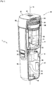
figure 1 représente une vue en perspective en coupe de l'appareil de confection de stockage.Thefigure 1 is a sectional perspective view of the storage building apparatus. -
La
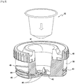
figure 2 représente une vue en perspective en demi-coupe partielle de l'appareil de confection d'infusion en position de remplissage.Thefigure 2 shows a perspective view in partial half-section of the infusion preparation apparatus in the filling position. -
La
figure 3 représente une vue en perspective en demi-coupe d'une partie intérieure de la partie d'infusion ainsi qu'une dose de produit à infuser.Thefigure 3 shows a perspective view in half-section of an interior part of the infusion part as well as a dose of product to be infused. -
La
figure 4 représente une vue en perspective en demi-coupe d'une partie extérieure de la partie d'infusion.Thefigure 4 shows a perspective view in half-section of an exterior part of the infusion part. -
La
figure 5 représente une vue en coupe de la partie d'infusion fixée au corps de l'appareil.Thefigure 5 shows a sectional view of the infusion part attached to the body of the device.
La
L'appareil 1 est une machine à café permettant de préparer des expressos. La dose de produit à infuser à utiliser dans cet appareil est donc une dosette de café en poudre et le liquide est de l'eau, mais l'invention est applicable à tout autre type de produits à infuser, comme expliqué précédemment.The appliance 1 is a coffee machine for preparing espresso. The dose of product to be infused to be used in this device is therefore a powdered coffee pod and the liquid is water, but the invention is applicable to any other type of product to be infused, as explained above.
L'appareil 1 comporte un corps 10 et une partie d'infusion 40. Sur la
Le corps 10, qui est de forme allongée selon l'axe X, comprend un réservoir chauffant 30, un moyen de pressurisation 20 et un système de commande électronique 15.The
Le réservoir chauffant 30 sert à contenir l'eau nécessaire à la préparation du café, et à chauffer celle-ci à l'aide d'un système de chauffage 11, afin de porter l'eau qu'il contient à la température nécessaire pour la préparation du café (soit 95°C environ).The
Le moyen de pressurisation 20, qui comprend principalement une pompe, sert à mettre sous pression l'eau chauffée et à pomper une certaine quantité d'eau de manière à la faire passer à travers la dose de café, afin de réaliser la quantité de café souhaitée, de manière connue en soi.The pressurization means 20, which mainly comprises a pump, serves to pressurize the heated water and to pump a certain quantity of water so as to make it pass through the dose of coffee, in order to achieve the quantity of coffee. desired, in a manner known per se.
Le système de commande électronique 15 sert à commander les opérations de préparation du café. Dans ce but, il comporte deux boutons de commande, disposés sur la surface extérieure du corps 10 : un bouton de commande de chauffage 12, permettant de déclencher le chauffage de l'eau contenue dans le réservoir, et un bouton de commande d'infusion 21, permettant de déclencher la préparation du café.The
L'appareil 1 comprend également un logement 17 pour un moyen de stockage électrique tel qu'une batterie, ainsi qu'une entrée d'alimentation électrique 19 située en partie inférieure du corps 10 ou sur un côté du corps 10. Cette entrée d'alimentation électrique 19 permet par exemple de connecter l'appareil 1 à des alimentations de basses (entre 50 V et 1000 V en courant alternatif, entre 120 V et 1500 V en courant continu) et très basses tensions (moins de 50 V en courant alternatif, moins de 120 V en courant continu), par exemple une prise secteur à 120, 220V ou 230V, ou une batterie de véhicule de 12 V ou 24 V au moyen d'une prise USB, allume-cigare ou autre. L'appareil 1 peut aussi être réalisé pour ne comporter que l'un parmi le logement 17 pour moyen de stockage et l'entrée d'alimentation électrique 19.The apparatus 1 also comprises a
L'appareil de plus comporte un régulateur de tension 18, connecté au moyen de pressurisation 20 et permettant d'alimenter le moyen de pressurisation 20 avec une tension constante, et ainsi assurer une pression constante lors de la pressurisation du réservoir 30 au cours de la préparation de l'infusion. Le régulateur de tension 18 peut aussi être inclus dans le système de commande électronique 15, comme représenté sur la
La forme oblongue de l'appareil 1 ainsi que son diamètre permettent aisément de l'intégrer dans un porte-gobelet de véhicule. Par exemple, l'appareil 1 a un diamètre maximum de 100 mm sur la totalité de l'appareil 1, ou bien seulement une partie inférieure de l'appareil. Cela permet le stockage de l'appareil par exemple dans une voiture ou un train, et permet de faciliter les opérations de préparation d'infusion en libérant les mains de l'utilisateur.The oblong shape of the device 1 as well as its diameter make it easy to integrate it into a vehicle cup holder. For example, the device 1 has a maximum diameter of 100 mm over the whole of the device 1, or else only a lower part of the device. This allows the device to be stored, for example in a car or a train, and makes it possible to facilitate infusion preparation operations by freeing the hands of the user.
Tout ou partie du réservoir 30 peut être formé d'une ou plusieurs couches isolantes, par exemple en disposant une couche de quasi-vide entre deux couches de matériaux sur le modèle d'un vase Dewar.All or part of the
La
Dans ce mode de réalisation, la partie d'infusion 40 est ainsi placée à distance du réservoir en étant complètement séparée du corps 10. Naturellement, la présente divulgation peut également être mise en œuvre simplement en écartant (en plaçant à distance) la partie d'infusion de l'orifice du réservoir, sans détacher la partie d'infusion 40 du corps 10.In this embodiment, the
Comme on le voit sur la
Cette fixation n'est pas limitée au vissage, et peut être réalisée par tout autre type de fixation équivalent, comme une fixation baïonnette, par emboîtage élastique ou tout autre moyen de fixation réversible adéquat.This fixing is not limited to screwing, and can be achieved by any other equivalent type of fixing, such as a bayonet fixing, by elastic fitting or any other suitable reversible fixing means.
Le réservoir 30 consiste en une cavité de grand volume au sein du corps 10, prévue pour contenir suffisamment de liquide pour réaliser une ou plusieurs tasses de café. La partie d'infusion 40 peut être placée à distance de l'orifice d'emplissage du réservoir 30, et notamment est détachable de la partie supérieure du réservoir 30, dans le but d'offrir un large orifice de remplissage sans goulot d'étranglement, par exemple de section supérieure à 50%, de préférence 75%, de la surface maximale d'une section horizontale du corps 10 perpendiculaire à l'axe X. Cela permet à l'utilisateur de procéder aisément au remplissage du réservoir 30, par exemple en versant de l'eau à partir d'une bouteille ou d'une gourde ne disposant pas de bec de versage précis et donc de limiter le risque de salissure.The
Le système de chauffage 11 comprend principalement un élément chauffant 13 sous forme d'une résistance chauffante, une sonde de température 14 et un système électronique 15. La résistance chauffante 13 permet de chauffer l'eau contenue dans le réservoir 30, et la température est mesurée par la sonde de température 14. La résistance chauffante 13 et la sonde de température 14 sont disposées sur une partie inférieure du réservoir 30 lorsque l'appareil 1 est en position de remplissage afin d'assurer les opérations de mesure de température et de chauffage pour tout niveau de remplissage du réservoir 30.The
Le système électronique 15 permet de recevoir les instructions de pressurisation et de chauffage générées par le bouton de commande de pressurisation 21 et le bouton de commande de chauffage 12, et permet de commander le système de chauffage 11 et les moyens de pressurisation 20. L'instruction de température peut être prédéterminée, par exemple élever la température de l'eau contenue dans le réservoir 30 à une température en mémoire du système électronique 15, ou bien élever la température de l'eau contenue dans le réservoir 30 à une température définie par l'utilisateur, par exemple au moyen d'un affichage digital et d'une molette de sélection. Un tel contrôle permet de déterminer avec précision la température d'infusion, ce qui permet à l'appareil 1 d'être polyvalent en optimisant la qualité d'infusion de boissons diverses, par exemple du café ou du thé; et d'optimiser la consommation électrique d'un système nomade.The
Le réservoir 30 comprend une valve d'entrée d'air 36 permettant de réguler la pression à l'intérieur du réservoir fermé, notamment lors de la mise en fonctionnement du moyen de pressurisation. Cette valve d'entrée d'air 36 comporte en outre un clapet anti-retour permettant le passage de l'air tout en empêchant la sortie du liquide du réservoir 30.The
Le réservoir 30 contient également des indicateurs de niveau de remplissage, par exemple indiquant des niveaux correspondant pour un indicateur de premier niveau de remplissage 31 à un café expresso de 50 mL, et pour un indicateur de deuxième niveau de remplissage 32 à deux expressos de 50 mL ou un café long de 100 mL. Grâce à la large ouverture de remplissage, ces indicateurs de niveau de remplissage sont facilement visibles depuis l'orifice de remplissage par l'utilisateur qui peut ainsi contrôler précisément le niveau de remplissage et assurer une infusion complète et non diluée, ainsi qu'optimiser la consommation énergétique en évitant de chauffer du liquide qui ne sera pas utilisé pour la boisson. Les indicateurs niveaux de remplissage peuvent être détachables afin de faciliter une opération de maintenance ou de nettoyage du réservoir 30. Du fait de la large ouverture de remplissage, les indicateurs de niveau de remplissage peuvent être disposés de sorte de masquer tout ou partie du système de chauffage 11 et ainsi améliorer l'esthétique du produit. Par exemple, un indicateur de premier niveau de remplissage 31 peut masquer une admission du moyen de pressurisation 22, et un indicateur de deuxième niveau de remplissage 32 peut masquer une sonde de température 14.The
La partie d'infusion 40 comprend un couvercle 50, une jupe 53 et un récipient 56.The
Une partie de préhension 48 est formée sur la surface extérieure (ou sur une partie de cette surface) du récipient 56. Cette partie de préhension 48 permet de faciliter l'opération de fixation et de désassemblage de la partie d'infusion 40 au corps 10. Par exemple, la partie de préhension 48 peut n'être formée qu'aux points d'appui des doigts de l'utilisateur. Cette partie de préhension 48 peut être alors réalisée par des rugosités comme des stries ou des cannelures, ou bien par l'utilisation d'un matériau différent de la partie d'infusion 40 ayant des propriétés antidérapantes, par exemple un caoutchouc.A
La
L'intérieur du récipient 56 est creux et constitue la chambre d'infusion 41, qui permet de recevoir une dose 60 de produit. Ce produit peut se trouver sous la forme d'une poudre ou d'une dosette solide de format standardisé et connu de l'homme de métier. Ainsi, cette chambre d'infusion 41 peut être de forme adaptée pour recevoir un ou plusieurs formats de dosette, par exemple de forme sensiblement tronconique, dont l'ouverture est plus large que la base afin de permettre l'insertion et le retrait de la dosette.The interior of the
La partie inférieure du récipient 56 comporte des organes de perçage 42 sous forme de pointes, afin de percer la dosette lorsque celle-ci est intégrée dans la chambre d'infusion 41. Un tel système est également adapté à recevoir une dose sous forme de poudre. Toutefois, pour faciliter le changement de dose et le nettoyage de la chambre d'infusion 41, la chambre d'infusion 41 peut être un élément détachable de la partie d'infusion 40 et plus particulièrement du récipient 56, et plusieurs chambres d'infusion 41 différentes peuvent être utilisées par exemple pour disposer de chambres d'infusion 41 avec et d'autres sans organes de perçage 42, ou bien pour permettre à l'utilisateur de préparer à l'avance plusieurs doses et n'avoir qu'à interchanger les chambres d'infusion 41, limitant ainsi limiter le nombre de manipulations à effectuer pour réaliser plusieurs boissons successives. La partie d'infusion 40 est détachable du corps 10 au niveau du récipient 56, de sorte qu'il est aussi possible d'interchanger des parties d'infusions 40 pour faciliter le changement de dose et le nettoyage de la partie d'infusion 40.The lower part of the
La partie supérieure de la partie d'infusion 40 contient une gouttière sur son contour. Cela permet, en recueillant les éventuelles doses de produit qui peuvent être versées hors de la chambre d'infusion 41, d'éviter les salissures dans le cadre d'une utilisation nomade ou non.The upper part of the
Un contour de la partie d'infusion 40 présente une rainure circulaire dans un plan perpendiculaire à l'axe principal X, et qui forme un conduit annulaire 43 avec une surface antagoniste du corps 10 lorsque la partie d'infusion 40 est montée sur le corps 10, comme dans la
Dans un autre mode de réalisation, le conduit annulaire 43 est formé entre deux surfaces antagonistes de la partie d'infusion 40 et du manchon 33 du corps 10, au moyen d'une rainure formée sur le corps 10, ou sur le corps 10 et la partie d'infusion 40. De plus, ce conduit annulaire 43 peut n'être formé que sur une partie de contour. Ces canaux d'admission 46 sont radiaux, allant du conduit annulaire 43, situé à l'extérieur de la partie d'infusion 40, vers la chambre d'infusion 41, à l'intérieur de la partie d'infusion 40. Une autre forme peut être également envisagée, comme une forme légèrement courbe ou toute autre forme connue de l'homme de métier pouvant limiter les pertes de charge du liquide sous pression prévu pour l'infusion, ainsi que faciliter un procédé de fabrication, par exemple moulage par injection.In another embodiment, the
La conduit annulaire 43 est délimité par deux joints d'étanchéité sur un contour de la partie d'infusion 40. Un joint d'étanchéité à l'air libre 44 permettant d'assurer l'étanchéité entre le liquide pressurisé du canal d'admission 46 et l'air, et un élément d'étanchéité du réservoir 45 permet d'assurer l'étanchéité entre le liquide pressurisé dans le canal d'admission 46 et le réservoir 30. Ces éléments d'étanchéité sont de forme sensiblement torique et constitués chacun d'un caoutchouc disposé sur tout un contour intérieur du corps 10 de l'appareil 1 ou un contour extérieur de la partie d'infusion 40.The
Les éléments d'étanchéité toriques sont de dimensions sensiblement identiques. Dans un tel cas, et avec une surface antagoniste du corps 10 complémentaire à la surface de fixation de la partie d'infusion 40, la course de l'élément d'étanchéité du réservoir 45 dans le corps 10 lors des opérations d'insertion et détachement serait supérieure. De fait, l'usure de l'élément d'étanchéité du réservoir 45 due au contact avec le corps 10 serait plus importante. Dans un tel cas, non seulement la durée de vie serait réduite, mais l'effort de serrage serait inégal, d'où un risque de fuite par la partie inférieure alors que l'état apparent du joint d'étanchéité est bon.The O-ring sealing elements are of substantially identical dimensions. In such a case, and with an opposing surface of the
Pour résoudre ce problème, l'élément d'étanchéité du réservoir 45 est conçu pour être de longueur légèrement inférieure dans une structure d'étanchéité « en escalier », et ainsi s'intégrer sur un contour de la partie d'infusion 40 de plus faible circonférence. Ainsi, et en concevant en conséquence la surface antagoniste du corps 10 de forme sensiblement tronconique, la course du joint inférieur sera inchangée, mais le contact sera réduit voire supprimé tant que la partie d'infusion 40 ne sera pas complètement insérée. En concevant le système d'attache réversible en conséquence, par exemple au moyen d'une fixation baïonnette ou vissage, la partie de fixation est correctement alignée avec le corps 10 tout le long de l'opération de fixation et le contact est assuré en fin de course. De plus, assurer le contact des parties d'étanchéité uniquement en fin de course permet d'éviter de comprimer l'air à l'insertion ou de détendre l'air au retrait, ce qui nécessiterait un effort supplémentaire de la part de l'utilisateur.To solve this problem, the sealing member of the
Dans un autre mode de réalisation, le canal ainsi que les éléments d'étanchéité ne sont pas disposés sur un contour extérieur de la partie d'infusion 40, mais sur une partie inférieure, c'est-à-dire sur un même plan perpendiculaire à l'axe du corps 10. Une telle configuration présente l'avantage d'assurer une meilleure uniformisation des efforts de serrage et donc une meilleure étanchéité.In another embodiment, the channel as well as the sealing elements are not arranged on an outer contour of the
La
La partie intérieure du couvercle 50 comporte un filtre 54 sous forme d'une grille de dimension sensiblement correspondante avec l'ouverture de la chambre d'infusion 41 lorsque l'appareil 1 est assemblé. Cette grille permet de laisser passer le produit infusé, et peut comporter des picots afin de perforer une deuxième extrémité de la dosette 60 par laquelle le produit infuser s'écoule. Le maillage de la grille est conçu pour ne laisser passer que la boisson infusée, et retenir les particules de produit telles que du thé infusé ou du marc de café. La grille peut être détachable afin d'être nettoyée, et éventuellement remplacée par une grille de maillage de finesse différente et adaptée à un autre type de boisson.The inner part of the
Dans le prolongement de la grille, l'extérieur du couvercle 50 comporte un orifice de sortie de la boisson infusée. Cet orifice de sortie 52 peut prendre la forme d'un simple trou communiquant avec la chambre d'infusion 41, ou bien d'une buse de sortie 52 formée ayant une ouverture annulaire communiquant avant la chambre d'infusion 41. Une ouverture de forme annulaire permet d'améliorer le brassage de l'infusion afin de réaliser une mousse recherchée des amateurs de café, et limiter les projections lors de l'infusion.In the extension of the grid, the outside of the
Le couvercle 50 présente une gouttière 51 sous forme d'un creux afin de récolter un liquide infusé résiduel. Par exemple, ce creux peut avoir une forme sensiblement conique autour de l'orifice de sortie 52. En plus, ou en remplacement de ce creux, une gouttière 51 de forme annulaire peut être formée sur un contour de l'orifice de sortie 52.The
La gouttière 51 permet de limiter l'écoulement latéral de la boisson infusée lorsque l'appareil 1 est reposé avec la partie d'infusion 40 vers le haut. Cela est particulièrement avantageux lors d'une utilisation nomade dans lequel l'utilisateur cherche absolument à éviter un écoulement de boisson éventuellement brûlante et salissante sur lui-même ou son environnement, par exemple dans un habitacle de voiture ou dans une tente. De plus, une gouttière 51 annulaire forme un creux permettant à l'utilisateur de reposer et stabiliser l'appareil 1 sur un verre ou une tasse, et ainsi procéder à l'infusion tout en limitant une projection de gouttelettes brûlantes et salissantes dues à l'écoulement de boisson sous pression.The
Le couvercle 50 et la fermeture 53 comportent une partie supérieure sensiblement circulaire, puis qui comprend une jupe s'étendant le long de l'axe X sur un contour extérieur de la partie d'infusion 40. Cette jupe comprend les parties extérieure et intérieure du couvercle 50 : la partie extérieure comprend une forme permettant d'épouser la forme du corps 10 pour améliorer l'aspect de l'appareil d'infusion, tandis que la partie intérieure comprend l'organe d'accrochage 55.The
La
Le manchon 33 du corps 10 est fixé à la partie d'infusion 40 au niveau des organes d'accrochage 49 et 34, et la jupe 53 est fixée via le manchon 33 au corps 10 de sorte que le manchon 33 est enserré entre un contour extérieur de la partie d'infusion 40 et un contour intérieur de la jupe 53.The
La liaison entre la jupe 53 et le manchon 33 s'effectue donc au niveau des organes d'accrochage 49 et 34 et entre le manchon 33 et la jupe 53 au niveau des organes d'accrochage 35 et 55.The connection between the
La partie de préhension 48 de la partie d'infusion 40 formée sur une surépaisseur permet de former une butée afin d'assurer un assemblage correct. Le liquide issu du moyen de pressurisation 20 arrive verticalement par l'échappement du moyen de pressurisation 23 située sur un contour à l'extérieur du réservoir 30. Arrivée au niveau de la partie d'infusion 40, l'échappement 23 est connecté à un coude d'admission 24 débouchant sur le canal d'admission 46 formé entre le corps 10 et la partie d'infusion 40, permettant de rediriger radialement vers la partie d'infusion 40 le liquide issu verticalement de l'échappement du moyen de pressurisation 23. La butée de la partie de préhension 48 permet d'assurer un alignement correct entre le coude d'admission 24 et le canal d'admission 46 afin d'assurer la liaison hydraulique entre les deux pièces.The
Le fonctionnement de l'appareil va maintenant être présenté.The operation of the apparatus will now be presented.
La première opération à réaliser consiste à remplir le réservoir 30. Pour ce faire, en position de remplissage, l'appareil 1 est disposé verticalement avec l'orifice de remplissage du réservoir 30 situé vers le haut. Dans une telle situation, l'orifice de remplissage est libéré en dégageant la partie d'infusion 40, et est accessible à l'utilisateur. Une ouverture de section comparable à la section de l'appareil 1 est dégagée, et permet à l'utilisateur un remplissage notablement facilité. Une telle position permet ensuite en fixant la partie d'infusion 40 au corps 10 de procéder au remplissage de la chambre d'infusion 41 par une dosette 60 ou en remplissant directement du produit à infuser. Le couvercle 50 peut ensuite être fixé sur la partie d'infusion 40. L'utilisateur peut ainsi déclencher la commande de chauffe lorsqu'il souhaite préparer son infusion.The first operation to be carried out consists in filling the
On peut alors lancer la préparation d'une tasse de café. Dans ce but, l'utilisateur commande d'abord le chauffage de l'eau en appuyant sur le bouton 89. Il place ensuite l'appareil en position d'infusion : l'appareil 1 est retourné par rapport à la position de remplissage : l'alignement des pièces est le même et la partie d'infusion 40 fixée au corps 10 est vers le bas. Dans cette position, un contenant peut être positionné sous l'appareil 1 en regard de la l'orifice de sortie 52 afin de recueillir la boisson infusée.You can then start the preparation of a cup of coffee. For this purpose, the user first controls the heating of the water by pressing button 89. He then places the appliance in the infusion position: the appliance 1 is turned over in relation to the filling position: the alignment of the parts is the same and the
Lorsque le chauffage est terminé, l'utilisateur peut alors déclencher la commande de pressurisation 21 permettant de faire circuler l'eau chaude contenue dans le réservoir 30 vers la chambre d'infusion 41.When the heating is finished, the user can then trigger the
Un mode d'utilisation de l'appareil 1 est prévu pour faciliter les opérations à deux mains en minimisant l'utilisation d'outils ou supports extérieurs, afin d'être adapté à une utilisation nomade. L'utilisateur peut dévisser la partie d'infusion 40 afin de libérer l'ouverture du réservoir 30. Le large orifice du réservoir 30 facilite un remplissage du réservoir 30 par le moyen d'une bouteille d'eau ou d'une gourde contenant de l'eau tempérée ou chaude. Les indicateurs de niveau présents dans le réservoir 30 sont aisément visibles par la large ouverture et permettent à l'utilisateur de verser précisément une quantité adaptée d'eau. La partie d'infusion 40 peut être ensuite vissée sur le corps 10. Du simple fait de la mise en place et de la fixation de la partie d'infusion sur le corps par vissage, le conduit annulaire 43 est constitué, et est dès lors mécaniquement raccordé au conduit hydraulique issu du moyen de pressurisation 20. De plus, grâce au serrage des éléments d'étanchéité 44 et 45 contre le manchon 33, l'étanchéité est assurée entre la jupe 53 et le manchon 33.A mode of use of the device 1 is provided to facilitate two-handed operations by minimizing the use of external tools or supports, in order to be suitable for mobile use. User can unscrew the
La commande de chauffage 12 peut alors être enclenchée si l'appareil 1 fonctionne sur batterie, ou après avoir préalablement branché l'appareil 1 sur une alimentation. Ensuite, le couvercle 50 de la partie d'infusion 40 peut être retiré afin de dégager la chambre d'infusion 41, dans laquelle est introduite la dose de produit 60. Cette opération peut être réalisée avant l'opération de remplissage de la chambre d'infusion 41, afin de limiter le temps d'attente dû à la commande de chauffage 12. Une fois le couvercle 50 de la partie d'infusion 40 vissé et le chauffage terminé, l'utilisateur peut retourner l'appareil 1 en deuxième position d'utilisation, et procéder à l'infusion au-dessus d'une tasse ou d'une gourde.The
Comme représenté dans la
Une liaison hydraulique 22 d'admission du moyen de pressurisation connecte le réservoir à l'admission du moyen de pressurisation 20 (non représenté ici) et est situé en un point de cette extrémité inférieure du réservoir 30 afin de limiter l'eau résiduelle dans le réservoir 30 ne pouvant pas être pompée vers la chambre d'infusion 41. La liaison hydraulique 22 entre le réservoir et le moyen de pressurisation 20 verticale traverse le corps 10 le long du réservoir 30 pour entrer dans le moyen de pressurisation 20 situé sous le réservoir 30. Un échappement 23 du moyen de pressurisation 20 est vertical et situé à proximité de la liaison hydraulique d'admission du moyen de pressurisation 22, et rejoint l'admission de la chambre d'infusion 41 au moyen d'un coude d'admission 24.An inlet
Le fond du réservoir 30, correspondant à une surface de la partie d'infusion 40, n'est pas limité à un dévers allant du centre vers une extrémité extérieure. Le fond du réservoir 30 peut avoir toute forme permettant le ruissellement du liquide vers un même point, ou toute autre surface ne présentant pas de cols et permettant d'assurer l'écoulement de tout point du réservoir 30 vers ce point où sera positionné. Par exemple, dans le cas d'une fixation à baïonnette, le positionnement des encoches détermine l'orientation de la partie d'infusion 40 lorsqu'elle est fixée aux corps 10, et le fond du réservoir 30 peut avoir une forme sans propriétés de symétrie comme une symétrie de révolution.The bottom of the
Le canal d'admission de la chambre d'infusion 46 formé entre le corps 10 et la partie d'infusion 40 relie le coude d'admission 24 et une extrémité de la chambre d'infusion 41. Le canal d'admission 46 peut présenter une inclinaison selon l'axe X. Par exemple, le canal d'admission 46 peut être incliné de l'extérieur vers l'intérieur en direction de l'orifice de sortie 52. Cette configuration permet de réduire l'angle du coude d'admission 24, et ainsi réduire la perte de charge au niveau du coude d'admission 24. Au contraire, le canal d'admission 46 peut présenter une inclinaison de l'extérieur vers l'intérieur en direction opposée à l'orifice de sortie 52. De cette façon et une fois l'infusion terminée et l'appareil 1 en position de repos, l'inclinaison empêche des résidus de boisson infusée de refluer et polluer le circuit hydraulique.The inlet channel of the
Un filtre 54 est disposé sur une extrémité de la chambre d'infusion 41 par laquelle la boisson infusée s'écoule, entre la chambre d'infusion 41 et l'orifice de sortie 52, afin de permettre le passage de la boisson infusée en filtrant le produit à infuser.A
Une extrémité inférieure de l'appareil 1 en position de repos comporte un tampon 16 permettant notamment de stabiliser l'appareil dans cette position.A lower end of the device 1 in the rest position comprises a
Claims (12)
Applications Claiming Priority (1)
| Application Number | Priority Date | Filing Date | Title |
|---|---|---|---|
| FR1913752A FR3104017B1 (en) | 2019-12-04 | 2019-12-04 | Infusion making device |
Publications (2)
| Publication Number | Publication Date |
|---|---|
| EP3831255A1 true EP3831255A1 (en) | 2021-06-09 |
| EP3831255B1 EP3831255B1 (en) | 2022-10-26 |
Family
ID=69572245
Family Applications (1)
| Application Number | Title | Priority Date | Filing Date |
|---|---|---|---|
| EP20211798.2A Active EP3831255B1 (en) | 2019-12-04 | 2020-12-04 | Apparatus for brewing infusions |
Country Status (2)
| Country | Link |
|---|---|
| EP (1) | EP3831255B1 (en) |
| FR (1) | FR3104017B1 (en) |
Cited By (1)
| Publication number | Priority date | Publication date | Assignee | Title |
|---|---|---|---|---|
| CN113827650A (en) * | 2021-09-15 | 2021-12-24 | 荔波荔泉民族医药有限公司 | Formula of anti-alcoholism medicine |
Citations (6)
| Publication number | Priority date | Publication date | Assignee | Title |
|---|---|---|---|---|
| FR2896676A1 (en) | 2006-02-01 | 2007-08-03 | Nielsen Innovation Sarl | APPARATUS FOR MAKING A BREW OF TEA OR COFFEE |
| CN105852646A (en) * | 2016-06-01 | 2016-08-17 | 苏州科贝尔实业有限公司 | Portable beverage brewing cup |
| EP3078306A1 (en) * | 2015-04-07 | 2016-10-12 | Ognibene S.p.A. | A machine for preparing hot beverages |
| EP3298932A1 (en) * | 2016-09-22 | 2018-03-28 | Foshan Imons Intelligence Technology Company Limited | A portable household beverage machine |
| US20190343320A1 (en) * | 2018-05-10 | 2019-11-14 | Shukuo Liu | In-car coffee maker |
| EP3569113A1 (en) * | 2018-05-14 | 2019-11-20 | Ningbo Jinyu Electric Appliance Co., Ltd. | Vehicle-mounted coffee maker with heating function and high-voltage extraction function |
-
2019
- 2019-12-04 FR FR1913752A patent/FR3104017B1/en not_active Expired - Fee Related
-
2020
- 2020-12-04 EP EP20211798.2A patent/EP3831255B1/en active Active
Patent Citations (6)
| Publication number | Priority date | Publication date | Assignee | Title |
|---|---|---|---|---|
| FR2896676A1 (en) | 2006-02-01 | 2007-08-03 | Nielsen Innovation Sarl | APPARATUS FOR MAKING A BREW OF TEA OR COFFEE |
| EP3078306A1 (en) * | 2015-04-07 | 2016-10-12 | Ognibene S.p.A. | A machine for preparing hot beverages |
| CN105852646A (en) * | 2016-06-01 | 2016-08-17 | 苏州科贝尔实业有限公司 | Portable beverage brewing cup |
| EP3298932A1 (en) * | 2016-09-22 | 2018-03-28 | Foshan Imons Intelligence Technology Company Limited | A portable household beverage machine |
| US20190343320A1 (en) * | 2018-05-10 | 2019-11-14 | Shukuo Liu | In-car coffee maker |
| EP3569113A1 (en) * | 2018-05-14 | 2019-11-20 | Ningbo Jinyu Electric Appliance Co., Ltd. | Vehicle-mounted coffee maker with heating function and high-voltage extraction function |
Cited By (1)
| Publication number | Priority date | Publication date | Assignee | Title |
|---|---|---|---|---|
| CN113827650A (en) * | 2021-09-15 | 2021-12-24 | 荔波荔泉民族医药有限公司 | Formula of anti-alcoholism medicine |
Also Published As
| Publication number | Publication date |
|---|---|
| FR3104017B1 (en) | 2023-01-13 |
| EP3831255B1 (en) | 2022-10-26 |
| FR3104017A1 (en) | 2021-06-11 |
Similar Documents
| Publication | Publication Date | Title |
|---|---|---|
| US20190069710A1 (en) | Beverage brewing device | |
| EP2785223B1 (en) | Machine for preparing beverages by extraction from capsules | |
| US20120285330A1 (en) | Beverage brewing device | |
| EP1791625B1 (en) | Device for heating milk and coffee machine comprising same | |
| EP1353591A1 (en) | Device for injecting water into an apparatus for preparing a beverage from a capsule | |
| EP2120654B1 (en) | Apparatus for preparing an infusion | |
| FR2774928A1 (en) | Component for supplying liquid to projection pistol | |
| EP3831255B1 (en) | Apparatus for brewing infusions | |
| EP3013192B1 (en) | Device for preparing infused drinks, comprising an injection tube leading into the infusion chamber | |
| EP0880330B1 (en) | Filter-holder for coffee machine of the espresso type | |
| EP0399034B1 (en) | Device for the presentation in superimposed layers of different density liquids, in particular, liquid foods | |
| EP3972929B1 (en) | Beverage dispensing device | |
| EP1893123A1 (en) | Method for packing a predetermined liquid substance dose in a straw and device for carrying out said method | |
| CA2916090A1 (en) | Device for preparing infused drinks, comprising a pivoting capsule support | |
| EP0509888B1 (en) | Closed cup including a mouth piece | |
| EP2506743B1 (en) | Appliance for preparing infused beverages having a removable store | |
| EP3517000B1 (en) | Beverage preparation machine with a dispensing head | |
| EP0449792B1 (en) | Improved filter holder for a percolator | |
| EP1259145A1 (en) | Filter-holder for espresso-coffee maker | |
| EP2378930B1 (en) | Infusion filtering device and appliance for brewing infusions fitted with such a device | |
| WO2024062176A1 (en) | Beverage-dispensing device | |
| JPH0728826B2 (en) | Coffee extractor | |
| CH86364A (en) | Device for the rapid preparation of coffee infusion. | |
| BE557871A (en) | ||
| BE498041A (en) |
Legal Events
| Date | Code | Title | Description |
|---|---|---|---|
| PUAI | Public reference made under article 153(3) epc to a published international application that has entered the european phase |
Free format text: ORIGINAL CODE: 0009012 |
|
| STAA | Information on the status of an ep patent application or granted ep patent |
Free format text: STATUS: THE APPLICATION HAS BEEN PUBLISHED |
|
| AK | Designated contracting states |
Kind code of ref document: A1 Designated state(s): AL AT BE BG CH CY CZ DE DK EE ES FI FR GB GR HR HU IE IS IT LI LT LU LV MC MK MT NL NO PL PT RO RS SE SI SK SM TR |
|
| STAA | Information on the status of an ep patent application or granted ep patent |
Free format text: STATUS: REQUEST FOR EXAMINATION WAS MADE |
|
| 17P | Request for examination filed |
Effective date: 20211130 |
|
| RBV | Designated contracting states (corrected) |
Designated state(s): AL AT BE BG CH CY CZ DE DK EE ES FI FR GB GR HR HU IE IS IT LI LT LU LV MC MK MT NL NO PL PT RO RS SE SI SK SM TR |
|
| GRAP | Despatch of communication of intention to grant a patent |
Free format text: ORIGINAL CODE: EPIDOSNIGR1 |
|
| STAA | Information on the status of an ep patent application or granted ep patent |
Free format text: STATUS: GRANT OF PATENT IS INTENDED |
|
| INTG | Intention to grant announced |
Effective date: 20220513 |
|
| GRAS | Grant fee paid |
Free format text: ORIGINAL CODE: EPIDOSNIGR3 |
|
| GRAA | (expected) grant |
Free format text: ORIGINAL CODE: 0009210 |
|
| STAA | Information on the status of an ep patent application or granted ep patent |
Free format text: STATUS: THE PATENT HAS BEEN GRANTED |
|
| AK | Designated contracting states |
Kind code of ref document: B1 Designated state(s): AL AT BE BG CH CY CZ DE DK EE ES FI FR GB GR HR HU IE IS IT LI LT LU LV MC MK MT NL NO PL PT RO RS SE SI SK SM TR |
|
| REG | Reference to a national code |
Ref country code: GB Ref legal event code: FG4D Free format text: NOT ENGLISH |
|
| REG | Reference to a national code |
Ref country code: CH Ref legal event code: EP |
|
| REG | Reference to a national code |
Ref country code: AT Ref legal event code: REF Ref document number: 1526431 Country of ref document: AT Kind code of ref document: T Effective date: 20221115 |
|
| REG | Reference to a national code |
Ref country code: DE Ref legal event code: R096 Ref document number: 602020005883 Country of ref document: DE |
|
| REG | Reference to a national code |
Ref country code: IE Ref legal event code: FG4D Free format text: LANGUAGE OF EP DOCUMENT: FRENCH |
|
| REG | Reference to a national code |
Ref country code: LT Ref legal event code: MG9D |
|
| REG | Reference to a national code |
Ref country code: NL Ref legal event code: MP Effective date: 20221026 |
|
| REG | Reference to a national code |
Ref country code: DE Ref legal event code: R082 Ref document number: 602020005883 Country of ref document: DE Representative=s name: CBDL PATENTANWAELTE GBR, DE |
|
| REG | Reference to a national code |
Ref country code: AT Ref legal event code: MK05 Ref document number: 1526431 Country of ref document: AT Kind code of ref document: T Effective date: 20221026 |
|
| PG25 | Lapsed in a contracting state [announced via postgrant information from national office to epo] |
Ref country code: NL Free format text: LAPSE BECAUSE OF FAILURE TO SUBMIT A TRANSLATION OF THE DESCRIPTION OR TO PAY THE FEE WITHIN THE PRESCRIBED TIME-LIMIT Effective date: 20221026 |
|
| PG25 | Lapsed in a contracting state [announced via postgrant information from national office to epo] |
Ref country code: SE Free format text: LAPSE BECAUSE OF FAILURE TO SUBMIT A TRANSLATION OF THE DESCRIPTION OR TO PAY THE FEE WITHIN THE PRESCRIBED TIME-LIMIT Effective date: 20221026 Ref country code: PT Free format text: LAPSE BECAUSE OF FAILURE TO SUBMIT A TRANSLATION OF THE DESCRIPTION OR TO PAY THE FEE WITHIN THE PRESCRIBED TIME-LIMIT Effective date: 20230227 Ref country code: NO Free format text: LAPSE BECAUSE OF FAILURE TO SUBMIT A TRANSLATION OF THE DESCRIPTION OR TO PAY THE FEE WITHIN THE PRESCRIBED TIME-LIMIT Effective date: 20230126 Ref country code: LT Free format text: LAPSE BECAUSE OF FAILURE TO SUBMIT A TRANSLATION OF THE DESCRIPTION OR TO PAY THE FEE WITHIN THE PRESCRIBED TIME-LIMIT Effective date: 20221026 Ref country code: FI Free format text: LAPSE BECAUSE OF FAILURE TO SUBMIT A TRANSLATION OF THE DESCRIPTION OR TO PAY THE FEE WITHIN THE PRESCRIBED TIME-LIMIT Effective date: 20221026 Ref country code: ES Free format text: LAPSE BECAUSE OF FAILURE TO SUBMIT A TRANSLATION OF THE DESCRIPTION OR TO PAY THE FEE WITHIN THE PRESCRIBED TIME-LIMIT Effective date: 20221026 Ref country code: AT Free format text: LAPSE BECAUSE OF FAILURE TO SUBMIT A TRANSLATION OF THE DESCRIPTION OR TO PAY THE FEE WITHIN THE PRESCRIBED TIME-LIMIT Effective date: 20221026 |
|
| PG25 | Lapsed in a contracting state [announced via postgrant information from national office to epo] |
Ref country code: RS Free format text: LAPSE BECAUSE OF FAILURE TO SUBMIT A TRANSLATION OF THE DESCRIPTION OR TO PAY THE FEE WITHIN THE PRESCRIBED TIME-LIMIT Effective date: 20221026 Ref country code: PL Free format text: LAPSE BECAUSE OF FAILURE TO SUBMIT A TRANSLATION OF THE DESCRIPTION OR TO PAY THE FEE WITHIN THE PRESCRIBED TIME-LIMIT Effective date: 20221026 Ref country code: LV Free format text: LAPSE BECAUSE OF FAILURE TO SUBMIT A TRANSLATION OF THE DESCRIPTION OR TO PAY THE FEE WITHIN THE PRESCRIBED TIME-LIMIT Effective date: 20221026 Ref country code: IS Free format text: LAPSE BECAUSE OF FAILURE TO SUBMIT A TRANSLATION OF THE DESCRIPTION OR TO PAY THE FEE WITHIN THE PRESCRIBED TIME-LIMIT Effective date: 20230226 Ref country code: HR Free format text: LAPSE BECAUSE OF FAILURE TO SUBMIT A TRANSLATION OF THE DESCRIPTION OR TO PAY THE FEE WITHIN THE PRESCRIBED TIME-LIMIT Effective date: 20221026 Ref country code: GR Free format text: LAPSE BECAUSE OF FAILURE TO SUBMIT A TRANSLATION OF THE DESCRIPTION OR TO PAY THE FEE WITHIN THE PRESCRIBED TIME-LIMIT Effective date: 20230127 |
|
| REG | Reference to a national code |
Ref country code: DE Ref legal event code: R097 Ref document number: 602020005883 Country of ref document: DE |
|
| PG25 | Lapsed in a contracting state [announced via postgrant information from national office to epo] |
Ref country code: SM Free format text: LAPSE BECAUSE OF FAILURE TO SUBMIT A TRANSLATION OF THE DESCRIPTION OR TO PAY THE FEE WITHIN THE PRESCRIBED TIME-LIMIT Effective date: 20221026 Ref country code: RO Free format text: LAPSE BECAUSE OF FAILURE TO SUBMIT A TRANSLATION OF THE DESCRIPTION OR TO PAY THE FEE WITHIN THE PRESCRIBED TIME-LIMIT Effective date: 20221026 Ref country code: EE Free format text: LAPSE BECAUSE OF FAILURE TO SUBMIT A TRANSLATION OF THE DESCRIPTION OR TO PAY THE FEE WITHIN THE PRESCRIBED TIME-LIMIT Effective date: 20221026 Ref country code: DK Free format text: LAPSE BECAUSE OF FAILURE TO SUBMIT A TRANSLATION OF THE DESCRIPTION OR TO PAY THE FEE WITHIN THE PRESCRIBED TIME-LIMIT Effective date: 20221026 Ref country code: CZ Free format text: LAPSE BECAUSE OF FAILURE TO SUBMIT A TRANSLATION OF THE DESCRIPTION OR TO PAY THE FEE WITHIN THE PRESCRIBED TIME-LIMIT Effective date: 20221026 |
|
| REG | Reference to a national code |
Ref country code: BE Ref legal event code: MM Effective date: 20221231 |
|
| PG25 | Lapsed in a contracting state [announced via postgrant information from national office to epo] |
Ref country code: SK Free format text: LAPSE BECAUSE OF FAILURE TO SUBMIT A TRANSLATION OF THE DESCRIPTION OR TO PAY THE FEE WITHIN THE PRESCRIBED TIME-LIMIT Effective date: 20221026 Ref country code: LU Free format text: LAPSE BECAUSE OF NON-PAYMENT OF DUE FEES Effective date: 20221204 Ref country code: AL Free format text: LAPSE BECAUSE OF FAILURE TO SUBMIT A TRANSLATION OF THE DESCRIPTION OR TO PAY THE FEE WITHIN THE PRESCRIBED TIME-LIMIT Effective date: 20221026 |
|
| PLBE | No opposition filed within time limit |
Free format text: ORIGINAL CODE: 0009261 |
|
| STAA | Information on the status of an ep patent application or granted ep patent |
Free format text: STATUS: NO OPPOSITION FILED WITHIN TIME LIMIT |
|
| 26N | No opposition filed |
Effective date: 20230727 |
|
| PG25 | Lapsed in a contracting state [announced via postgrant information from national office to epo] |
Ref country code: IE Free format text: LAPSE BECAUSE OF NON-PAYMENT OF DUE FEES Effective date: 20221204 |
|
| PG25 | Lapsed in a contracting state [announced via postgrant information from national office to epo] |
Ref country code: SI Free format text: LAPSE BECAUSE OF FAILURE TO SUBMIT A TRANSLATION OF THE DESCRIPTION OR TO PAY THE FEE WITHIN THE PRESCRIBED TIME-LIMIT Effective date: 20221026 Ref country code: BE Free format text: LAPSE BECAUSE OF NON-PAYMENT OF DUE FEES Effective date: 20221231 |
|
| PGFP | Annual fee paid to national office [announced via postgrant information from national office to epo] |
Ref country code: FR Payment date: 20231221 Year of fee payment: 4 |
|
| PG25 | Lapsed in a contracting state [announced via postgrant information from national office to epo] |
Ref country code: CY Free format text: LAPSE BECAUSE OF FAILURE TO SUBMIT A TRANSLATION OF THE DESCRIPTION OR TO PAY THE FEE WITHIN THE PRESCRIBED TIME-LIMIT Effective date: 20221026 |
|
| PGFP | Annual fee paid to national office [announced via postgrant information from national office to epo] |
Ref country code: DE Payment date: 20240115 Year of fee payment: 4 |
|
| PG25 | Lapsed in a contracting state [announced via postgrant information from national office to epo] |
Ref country code: MK Free format text: LAPSE BECAUSE OF FAILURE TO SUBMIT A TRANSLATION OF THE DESCRIPTION OR TO PAY THE FEE WITHIN THE PRESCRIBED TIME-LIMIT Effective date: 20221026 Ref country code: IT Free format text: LAPSE BECAUSE OF FAILURE TO SUBMIT A TRANSLATION OF THE DESCRIPTION OR TO PAY THE FEE WITHIN THE PRESCRIBED TIME-LIMIT Effective date: 20221026 |
|
| PG25 | Lapsed in a contracting state [announced via postgrant information from national office to epo] |
Ref country code: MC Free format text: LAPSE BECAUSE OF FAILURE TO SUBMIT A TRANSLATION OF THE DESCRIPTION OR TO PAY THE FEE WITHIN THE PRESCRIBED TIME-LIMIT Effective date: 20221026 |
|
| PG25 | Lapsed in a contracting state [announced via postgrant information from national office to epo] |
Ref country code: MC Free format text: LAPSE BECAUSE OF FAILURE TO SUBMIT A TRANSLATION OF THE DESCRIPTION OR TO PAY THE FEE WITHIN THE PRESCRIBED TIME-LIMIT Effective date: 20221026 |
|
| PG25 | Lapsed in a contracting state [announced via postgrant information from national office to epo] |
Ref country code: BG Free format text: LAPSE BECAUSE OF FAILURE TO SUBMIT A TRANSLATION OF THE DESCRIPTION OR TO PAY THE FEE WITHIN THE PRESCRIBED TIME-LIMIT Effective date: 20221026 |
|
| REG | Reference to a national code |
Ref country code: CH Ref legal event code: PL |