EP3829807B1 - Verbindungsteile für einen bearbeitungskopf zur thermischen materialbearbeitung, insbesondere für einen plasmabrennerkopf - Google Patents
Verbindungsteile für einen bearbeitungskopf zur thermischen materialbearbeitung, insbesondere für einen plasmabrennerkopf Download PDFInfo
- Publication number
- EP3829807B1 EP3829807B1 EP19752085.1A EP19752085A EP3829807B1 EP 3829807 B1 EP3829807 B1 EP 3829807B1 EP 19752085 A EP19752085 A EP 19752085A EP 3829807 B1 EP3829807 B1 EP 3829807B1
- Authority
- EP
- European Patent Office
- Prior art keywords
- longitudinal axis
- connecting part
- distance
- ring
- max
- Prior art date
- Legal status (The legal status is an assumption and is not a legal conclusion. Google has not performed a legal analysis and makes no representation as to the accuracy of the status listed.)
- Active
Links
Images














Classifications
-
- B—PERFORMING OPERATIONS; TRANSPORTING
- B23—MACHINE TOOLS; METAL-WORKING NOT OTHERWISE PROVIDED FOR
- B23K—SOLDERING OR UNSOLDERING; WELDING; CLADDING OR PLATING BY SOLDERING OR WELDING; CUTTING BY APPLYING HEAT LOCALLY, e.g. FLAME CUTTING; WORKING BY LASER BEAM
- B23K37/00—Auxiliary devices or processes, not specially adapted for a procedure covered by only one of the other main groups of this subclass
-
- B—PERFORMING OPERATIONS; TRANSPORTING
- B23—MACHINE TOOLS; METAL-WORKING NOT OTHERWISE PROVIDED FOR
- B23K—SOLDERING OR UNSOLDERING; WELDING; CLADDING OR PLATING BY SOLDERING OR WELDING; CUTTING BY APPLYING HEAT LOCALLY, e.g. FLAME CUTTING; WORKING BY LASER BEAM
- B23K9/00—Arc welding or cutting
- B23K9/16—Arc welding or cutting making use of shielding gas
-
- B—PERFORMING OPERATIONS; TRANSPORTING
- B23—MACHINE TOOLS; METAL-WORKING NOT OTHERWISE PROVIDED FOR
- B23K—SOLDERING OR UNSOLDERING; WELDING; CLADDING OR PLATING BY SOLDERING OR WELDING; CUTTING BY APPLYING HEAT LOCALLY, e.g. FLAME CUTTING; WORKING BY LASER BEAM
- B23K10/00—Welding or cutting by means of a plasma
- B23K10/02—Plasma welding
-
- B—PERFORMING OPERATIONS; TRANSPORTING
- B23—MACHINE TOOLS; METAL-WORKING NOT OTHERWISE PROVIDED FOR
- B23K—SOLDERING OR UNSOLDERING; WELDING; CLADDING OR PLATING BY SOLDERING OR WELDING; CUTTING BY APPLYING HEAT LOCALLY, e.g. FLAME CUTTING; WORKING BY LASER BEAM
- B23K26/00—Working by laser beam, e.g. welding, cutting or boring
- B23K26/14—Working by laser beam, e.g. welding, cutting or boring using a fluid stream, e.g. a jet of gas, in conjunction with the laser beam; Nozzles therefor
-
- B—PERFORMING OPERATIONS; TRANSPORTING
- B23—MACHINE TOOLS; METAL-WORKING NOT OTHERWISE PROVIDED FOR
- B23K—SOLDERING OR UNSOLDERING; WELDING; CLADDING OR PLATING BY SOLDERING OR WELDING; CUTTING BY APPLYING HEAT LOCALLY, e.g. FLAME CUTTING; WORKING BY LASER BEAM
- B23K26/00—Working by laser beam, e.g. welding, cutting or boring
- B23K26/14—Working by laser beam, e.g. welding, cutting or boring using a fluid stream, e.g. a jet of gas, in conjunction with the laser beam; Nozzles therefor
- B23K26/1462—Nozzles; Features related to nozzles
- B23K26/1482—Detachable nozzles, e.g. exchangeable or provided with breakaway lines
-
- B—PERFORMING OPERATIONS; TRANSPORTING
- B23—MACHINE TOOLS; METAL-WORKING NOT OTHERWISE PROVIDED FOR
- B23K—SOLDERING OR UNSOLDERING; WELDING; CLADDING OR PLATING BY SOLDERING OR WELDING; CUTTING BY APPLYING HEAT LOCALLY, e.g. FLAME CUTTING; WORKING BY LASER BEAM
- B23K26/00—Working by laser beam, e.g. welding, cutting or boring
- B23K26/20—Bonding
- B23K26/32—Bonding taking account of the properties of the material involved
-
- B—PERFORMING OPERATIONS; TRANSPORTING
- B23—MACHINE TOOLS; METAL-WORKING NOT OTHERWISE PROVIDED FOR
- B23K—SOLDERING OR UNSOLDERING; WELDING; CLADDING OR PLATING BY SOLDERING OR WELDING; CUTTING BY APPLYING HEAT LOCALLY, e.g. FLAME CUTTING; WORKING BY LASER BEAM
- B23K26/00—Working by laser beam, e.g. welding, cutting or boring
- B23K26/70—Auxiliary operations or equipment
-
- B—PERFORMING OPERATIONS; TRANSPORTING
- B23—MACHINE TOOLS; METAL-WORKING NOT OTHERWISE PROVIDED FOR
- B23K—SOLDERING OR UNSOLDERING; WELDING; CLADDING OR PLATING BY SOLDERING OR WELDING; CUTTING BY APPLYING HEAT LOCALLY, e.g. FLAME CUTTING; WORKING BY LASER BEAM
- B23K26/00—Working by laser beam, e.g. welding, cutting or boring
- B23K26/70—Auxiliary operations or equipment
- B23K26/702—Auxiliary equipment
-
- B—PERFORMING OPERATIONS; TRANSPORTING
- B23—MACHINE TOOLS; METAL-WORKING NOT OTHERWISE PROVIDED FOR
- B23K—SOLDERING OR UNSOLDERING; WELDING; CLADDING OR PLATING BY SOLDERING OR WELDING; CUTTING BY APPLYING HEAT LOCALLY, e.g. FLAME CUTTING; WORKING BY LASER BEAM
- B23K9/00—Arc welding or cutting
- B23K9/24—Features related to electrodes
- B23K9/28—Supporting devices for electrodes
- B23K9/29—Supporting devices adapted for making use of shielding means
- B23K9/291—Supporting devices adapted for making use of shielding means the shielding means being a gas
-
- B—PERFORMING OPERATIONS; TRANSPORTING
- B23—MACHINE TOOLS; METAL-WORKING NOT OTHERWISE PROVIDED FOR
- B23K—SOLDERING OR UNSOLDERING; WELDING; CLADDING OR PLATING BY SOLDERING OR WELDING; CUTTING BY APPLYING HEAT LOCALLY, e.g. FLAME CUTTING; WORKING BY LASER BEAM
- B23K9/00—Arc welding or cutting
- B23K9/32—Accessories
- B23K9/321—Protecting means
-
- F—MECHANICAL ENGINEERING; LIGHTING; HEATING; WEAPONS; BLASTING
- F16—ENGINEERING ELEMENTS AND UNITS; GENERAL MEASURES FOR PRODUCING AND MAINTAINING EFFECTIVE FUNCTIONING OF MACHINES OR INSTALLATIONS; THERMAL INSULATION IN GENERAL
- F16J—PISTONS; CYLINDERS; SEALINGS
- F16J15/00—Sealings
- F16J15/02—Sealings between relatively-stationary surfaces
- F16J15/06—Sealings between relatively-stationary surfaces with solid packing compressed between sealing surfaces
-
- F—MECHANICAL ENGINEERING; LIGHTING; HEATING; WEAPONS; BLASTING
- F16—ENGINEERING ELEMENTS AND UNITS; GENERAL MEASURES FOR PRODUCING AND MAINTAINING EFFECTIVE FUNCTIONING OF MACHINES OR INSTALLATIONS; THERMAL INSULATION IN GENERAL
- F16J—PISTONS; CYLINDERS; SEALINGS
- F16J15/00—Sealings
- F16J15/02—Sealings between relatively-stationary surfaces
- F16J15/06—Sealings between relatively-stationary surfaces with solid packing compressed between sealing surfaces
- F16J15/062—Sealings between relatively-stationary surfaces with solid packing compressed between sealing surfaces characterised by the geometry of the seat
-
- F—MECHANICAL ENGINEERING; LIGHTING; HEATING; WEAPONS; BLASTING
- F16—ENGINEERING ELEMENTS AND UNITS; GENERAL MEASURES FOR PRODUCING AND MAINTAINING EFFECTIVE FUNCTIONING OF MACHINES OR INSTALLATIONS; THERMAL INSULATION IN GENERAL
- F16J—PISTONS; CYLINDERS; SEALINGS
- F16J9/00—Piston-rings, e.g. non-metallic piston-rings, seats therefor; Ring sealings of similar construction
-
- H—ELECTRICITY
- H05—ELECTRIC TECHNIQUES NOT OTHERWISE PROVIDED FOR
- H05H—PLASMA TECHNIQUE; PRODUCTION OF ACCELERATED ELECTRICALLY-CHARGED PARTICLES OR OF NEUTRONS; PRODUCTION OR ACCELERATION OF NEUTRAL MOLECULAR OR ATOMIC BEAMS
- H05H1/00—Generating plasma; Handling plasma
- H05H1/24—Generating plasma
- H05H1/26—Plasma torches
- H05H1/32—Plasma torches using an arc
- H05H1/34—Details, e.g. electrodes, nozzles
- H05H1/3423—Connecting means, e.g. electrical connecting means or fluid connections
-
- B—PERFORMING OPERATIONS; TRANSPORTING
- B23—MACHINE TOOLS; METAL-WORKING NOT OTHERWISE PROVIDED FOR
- B23K—SOLDERING OR UNSOLDERING; WELDING; CLADDING OR PLATING BY SOLDERING OR WELDING; CUTTING BY APPLYING HEAT LOCALLY, e.g. FLAME CUTTING; WORKING BY LASER BEAM
- B23K10/00—Welding or cutting by means of a plasma
-
- B—PERFORMING OPERATIONS; TRANSPORTING
- B23—MACHINE TOOLS; METAL-WORKING NOT OTHERWISE PROVIDED FOR
- B23K—SOLDERING OR UNSOLDERING; WELDING; CLADDING OR PLATING BY SOLDERING OR WELDING; CUTTING BY APPLYING HEAT LOCALLY, e.g. FLAME CUTTING; WORKING BY LASER BEAM
- B23K37/00—Auxiliary devices or processes, not specially adapted for a procedure covered by only one of the other main groups of this subclass
- B23K37/003—Cooling means for welding or cutting
-
- F—MECHANICAL ENGINEERING; LIGHTING; HEATING; WEAPONS; BLASTING
- F16—ENGINEERING ELEMENTS AND UNITS; GENERAL MEASURES FOR PRODUCING AND MAINTAINING EFFECTIVE FUNCTIONING OF MACHINES OR INSTALLATIONS; THERMAL INSULATION IN GENERAL
- F16L—PIPES; JOINTS OR FITTINGS FOR PIPES; SUPPORTS FOR PIPES, CABLES OR PROTECTIVE TUBING; MEANS FOR THERMAL INSULATION IN GENERAL
- F16L21/00—Joints with sleeve or socket
- F16L21/02—Joints with sleeve or socket with elastic sealing rings between pipe and sleeve or between pipe and socket, e.g. with rolling or other prefabricated profiled rings
- F16L21/03—Joints with sleeve or socket with elastic sealing rings between pipe and sleeve or between pipe and socket, e.g. with rolling or other prefabricated profiled rings placed in the socket before connection
-
- F—MECHANICAL ENGINEERING; LIGHTING; HEATING; WEAPONS; BLASTING
- F16—ENGINEERING ELEMENTS AND UNITS; GENERAL MEASURES FOR PRODUCING AND MAINTAINING EFFECTIVE FUNCTIONING OF MACHINES OR INSTALLATIONS; THERMAL INSULATION IN GENERAL
- F16L—PIPES; JOINTS OR FITTINGS FOR PIPES; SUPPORTS FOR PIPES, CABLES OR PROTECTIVE TUBING; MEANS FOR THERMAL INSULATION IN GENERAL
- F16L21/00—Joints with sleeve or socket
- F16L21/02—Joints with sleeve or socket with elastic sealing rings between pipe and sleeve or between pipe and socket, e.g. with rolling or other prefabricated profiled rings
- F16L21/035—Joints with sleeve or socket with elastic sealing rings between pipe and sleeve or between pipe and socket, e.g. with rolling or other prefabricated profiled rings placed around the spigot end before connection
Definitions
- Processing heads for thermal material processing such as plasma torch heads, laser heads and plasma laser heads, are generally used for the thermal processing of a wide variety of materials, such as metallic and non-metallic materials, for example for cutting, welding, marking or, more generally, for heating.
- Plasma torches typically consist of a torch body, an electrode, a nozzle, and a nozzle holder. Modern plasma torches also feature a nozzle protection cap mounted over the nozzle. A nozzle is often secured with a nozzle cap.
- the components subject to wear during operation of the plasma torch due to the high thermal stress caused by the arc include, in particular, the electrode, the nozzle, the nozzle cap, the nozzle protection cap, the nozzle protection cap holder, and the plasma gas guide and secondary gas guide components. These components can be easily replaced by an operator and are therefore considered wear parts.
- the plasma torches are connected via cables to a power source and a gas supply that feeds the plasma torch. Furthermore, the plasma torch can be connected to a cooling device for a cooling medium, such as a cooling liquid.
- Plasma cutting torches are particularly susceptible to high thermal stress. This is due to the severe constriction of the plasma jet by the nozzle bore. Small bores are used here to generate high current densities of 50 to 150 A/ mm2 in the nozzle bore, high energy densities of approximately 2 ⁇ 103 W/ cm2 , and high temperatures of up to 30,000 K. Furthermore, higher gas pressures, typically up to 12 bar, are used in plasma cutting torches. The combination of high temperature and high kinetic energy of the plasma gas flowing through the nozzle bore melts the workpiece and expels the molten metal. A kerf is created, and the workpiece is severed. Plasma cutting often uses oxidizing gases to cut unalloyed or low-alloy steels, and non-oxidizing gases to cut high-alloy steels or non-ferrous metals.
- the pilot arc exits through the nozzle bore and strikes the workpiece, ionizing the path to the workpiece. This allows the arc to form between the electrode and the workpiece. This arc is also called the main arc.
- the pilot arc can be switched off during the main arc. However, it can also continue to operate. In plasma cutting, this arc is often switched off to avoid placing additional strain on the nozzle.
- the electrode and nozzle are subject to high thermal stress and require cooling. At the same time, they must also conduct the electrical current required to form the arc. Therefore, materials with good thermal and electrical conductivity are used, usually metals such as copper, silver, aluminum, tin, zinc, iron, or alloys containing at least one of these metals.
- the electrode often consists of an electrode holder and an emission insert made of a material with a high melting temperature ( ⁇ 2000°C) and a lower electron work function than the electrode holder.
- Materials used for the emission insert include non-oxidizing plasma gases such as argon, hydrogen, nitrogen, helium, and mixtures thereof, or tungsten.
- oxidizing gases such as oxygen, air, and mixtures thereof, nitrogen-oxygen mixtures and mixtures with other gases, hafnium, or zirconium.
- the high-temperature material can be pressed into an electrode holder made of a material with good thermal and electrical conductivity, for example, using a positive and/or friction fit.
- the cooling of the electrode and nozzle can be achieved by gas, for example, the plasma gas or a secondary gas flowing along the outside of the nozzle.
- gas for example, the plasma gas or a secondary gas flowing along the outside of the nozzle.
- a liquid for example, water
- the electrode and/or nozzle are often cooled directly with the liquid, i.e., the liquid is in direct contact with the electrode and/or nozzle.
- a Nozzle cap To guide the cooling liquid around the nozzle, a Nozzle cap, the inner surface of which forms a coolant chamber with the outer surface of the nozzle in which the coolant flows.
- Modern plasma cutting torches also have a nozzle protection cap outside the nozzle and/or nozzle cap.
- the inner surface of the nozzle protection cap and the outer surface of the nozzle or nozzle cap form a space through which a secondary or shielding gas flows.
- the secondary or shielding gas exits the bore of the nozzle protection cap and envelops the plasma jet, creating a defined atmosphere around it.
- the secondary gas also protects the nozzle and nozzle protection cap from arcs that can form between the nozzle and the workpiece. These are known as double arcs and can damage the nozzle.
- the nozzle and nozzle protection cap are subject to significant stress from hot material spraying up.
- the secondary gas whose volume flow can be higher during piercing than during cutting, keeps the spraying material away from the nozzle and nozzle protection cap, thus protecting them from damage.
- the nozzle protection cap is also subject to high thermal stress and requires cooling. Therefore, materials with good thermal and electrical conductivity are used, usually metals such as copper, silver, aluminum, tin, zinc, iron, or alloys containing at least one of these metals.
- the electrode and nozzle can also be cooled indirectly.
- they are in contact with a component made of a material that conducts heat and electricity well, usually a metal such as copper, silver, aluminum, tin, zinc, iron, or alloys containing at least one of these metals.
- This component is in turn cooled directly, meaning it is in direct contact with the usually flowing coolant.
- These components can simultaneously serve as holders or supports for the electrode, nozzle, nozzle cap, or nozzle protection cap, dissipating heat and supplying current.
- the nozzle protection cap is usually cooled solely by the secondary gas. Arrangements are also known in which the secondary gas cap is cooled directly or indirectly by a cooling liquid.
- Laser heads essentially consist of a body, an optical system within the body for focusing the laser beam, connections for the laser light supply or fiber optic cable, gas (cutting gas and secondary gas), and a cooling medium, as well as a nozzle with an opening that shapes the gas jet and through which the laser beam exits the laser head.
- the laser beam strikes a workpiece and is absorbed.
- the heated workpiece is melted and expelled (laser fusion cutting) or oxidized (laser flame cutting) in combination with the cutting gas.
- the laser cutting head may also be fitted with a nozzle protection cap outside the nozzle.
- the inner surface of the nozzle protection cap and the outer surface of the nozzle or nozzle cap form a chamber through which a secondary or shielding gas flows.
- the secondary or shielding gas exits the bore of the nozzle protection cap and envelops the laser beam, creating a defined atmosphere around it.
- the secondary gas also protects the nozzle. Particularly when piercing the workpiece, the nozzle is subjected to significant stress from hot material spraying up.
- the secondary gas whose flow rate may be higher during piercing than during cutting, keeps the spraying material away from the nozzle and thus protects it from damage.
- Processing heads in which both the plasma and laser processes are used simultaneously so-called plasma laser cutting heads, have features of the Plasma torch head and laser head. Here, the features and thus the advantages of both processes are combined.
- material can basically be cut, welded, labeled, ablated or generally heated.
- Plasma torches or processing heads for thermal processes such as cutting or welding, often involve joining parts that come into contact with fluids (gases, liquids). These fluids flow along the surfaces of the torch parts or through openings (bores, channels). These may be individual parts, such as wear parts, that wear out during operation and require frequent replacement by the operator.
- Tight means that no fluid, i.e., no gas and/or liquid, up to a pressure of 20 bar, can penetrate the sealing point from the inside to the outside or from the outside to the inside.
- the arrangements known so far consist of a groove extending on the cylindrical outer or inner surface on a circular circumference, in which an O-ring is located and an opposite, likewise cylindrical inner or outer surface of the wear part holder or another wear part, which also extends along a circular circumference.
- the O-ring protrudes from the groove on its circumference and, when joined, is pressed into the groove by contact with the opposite surface, thereby deforming it.
- the O-ring is made of an elastically deformable material, e.g., an elastomer.
- the cross-section of the groove should be at least the size of the cross-section of the O-ring's cord.
- the opposing surface of the wear part holder or the wear part is usually made of a material that is not elastically deformable or only slightly deformable, such as metal, ceramic, or a hard plastic.
- a material that is not elastically deformable or only slightly deformable such as metal, ceramic, or a hard plastic.
- the aim of the present invention is to reduce the force required for joining and/or, if possible, to ensure a clear axial, radial and rotational positioning to a longitudinal axis between the connecting parts, e.g. wearing parts.
- a connecting part 100, 200 for a machining head for thermal material processing comprising a body 106, 206 which extends along a longitudinal axis L, with an outer surface 110, 112, 120, 212 and/or inner surface 140, 240, 244 with a front end 102, 202 and a rear end 104, 204, wherein the outer surface 110 and/or the inner surface 240 has at least one circumferentially extending groove 130, 230 with a groove depth T130, T112, T120, T230, wherein the groove bottom 116, 216 of the groove 130, 230 has different distances D116 extending along the circumference through the longitudinal axis L and perpendicular to the longitudinal axis L between the opposite sections of the groove bottom 116, 216 of the groove 130, 230 and/or wherein at least one outer surface 112 and/or 120 has different distances D112, D120 along the circumference extending through the longitudinal axis L and perpendicular to the
- a connecting part 100, 200 for a Processing head for thermal material processing comprising a body 106, 206 which extends along a longitudinal axis L, with an outer surface 110, 112, 120, 212 and/or inner surface 140, 240, 244 with a front end 102, 202 and a rear end 104, 204, wherein the outer surface 110 and/or the inner surface 240 has at least one circumferentially extending groove 130, 230 with a groove width B130, B230 and a groove depth T130, T112, T120, T230 with an O-ring 132, 232 or profile ring with a cord thickness Sa, wherein the innermost to the longitudinal axis L directed surface 132i of the O-ring 132, 232 has different distances D132i along the circumference extending through the longitudinal axis L and perpendicular to the longitudinal axis L between the opposite sections of the innermost surface 132i of the O-ring and/or wherein the outer
- the advantages of the invention are achieved even with a relatively small change in size in order to realize space-saving arrangements, in particular for wearing parts.
- Figure 1 shows a first connecting part 100 comprising a body 106 extending along a longitudinal axis L, with a front end 102 and a rear end 104, with an inner surface 140 and with an outer surface 110 comprising a plurality of surfaces 108, 112, 114, 116, 118, 120, 122, 124, 126 and 128.
- the rear end 104 has a surface (outer surface) 108.
- the first lateral boundary of the groove 130, the surface 114, has different distances L112 parallel to the longitudinal axis L from the rear end 104 of the connecting part 100.
- the minimum distance is designated L112 min and the maximum distance is designated L112 max .
- the second lateral boundary of the groove 130, the surface 118 has different distances L128 parallel to the longitudinal axis L to the front end 102 of the connecting part 100, different distances L120 to the surface 122 of the flange 125 and different distances L124 to the surface 126 of the flange 125.
- the Figure 1 shown The minimum distances of L128, L124 and L120 are designated L128 min , L124 min and L120 min and the maximum distances are designated L128 max , L124 max and L120 max .
- the surface 122 of the flange 125 can be used as an axial stop or for positioning axially to the longitudinal axis L in another connecting part, for example a Figure 2 shown connecting part 200.
- the Figures 1a to 1c show examples of different groove shapes of the groove 130, Figure 1a a rectangular groove, the Figure 1b a so-called trapezoidal groove and the Figure 1c a circular groove.
- a virtual center line M130 of the groove 130 runs circumferentially in the center of the groove base 116. This virtual center line also has different distances from the fixed point F around the circumference.
- Figure 1d shows the connecting part 100 from Figure 1 with an O-ring 132 in the groove 130.
- the O-ring 132 has a cord thickness Sa of 1.5 mm.
- a virtual center line M132 In the middle of the cord is a virtual center line M132.
- the O-ring 132 extends over the circumference in the groove 130.
- a virtual center line M132 has different distances L116a parallel to the longitudinal axis L from a fixed point F on the longitudinal axis L.
- the maximum distance L116a max in this example is 2/3 of the cord thickness Sa.
- the cord thickness Sa is 1.5 mm, so the maximum distance L116a max is 1 mm.
- the outer surface of the O-ring 132 facing toward the rear end 104 has different distances L112a from the rear end 104 parallel to the longitudinal axis L.
- the minimum distance is designated L112a min and the maximum distance is designated L112a max .
- the outer surface of the O-ring 132 facing towards the front end 102 has different distances L128a parallel to the longitudinal axis L from the front end 102, different distances L120a from the surface 122 of the flange 125 and different distances L124a from the surface 126 of the flange 125.
- the Figure 1d The minimum distances of L128a, L124a and L120a shown are designated L128a min , L124a min and L120a min and the maximum distances are designated L128a max , L124a max and L120a max .
- the respective outer surfaces of the O-ring 132 facing the nearer end thus have different axial distances parallel to the longitudinal axis L from the rear end 104 and the front end 102 as well as from the surfaces 122 and 126 of the flange 125.
- end 102 or a surface 122 or 126 of the flange corresponds to 2/3 of the cord thickness Sa, here 1 mm.
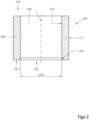
- Figure 2 shows an example of a second connecting part 200, into which the connecting part 100 from Figure 1d and Figure 4a It comprises a body 206 extending along a longitudinal axis L, having a front end 202 and a rear end 204, with an outer surface 212 and an inner surface 240.
- An opening 238 extends between the front end 202 and the rear end 204.
- a surface 222 which serves as a stop surface for the surface 122 of the connecting part 100 made of Figure 1 and a chamfer 242 which facilitates the insertion of the connecting part 100 into the opening 238 of the connecting part 200.
- the Figures 3a and 3b show an example of the connection from the first connecting part 100 of Figure 1d and the second connecting part 200 Figure 2 in different states.
- the O-ring 132 doesn't have to be deformed along its entire circumference at the beginning of the joining process; instead, it starts at one point and then "wanders" along the circumference. This reduces the required force and facilitates mating.
- Figure 3b shows, by way of example, the fully joined or nested connecting parts 100 and 200.
- the connection point or line is sealed by nesting the first connecting part 100 into the second connecting part 200 and the O-ring 132 in combination with the inner surface 240 for a fluid that can flow through the inner openings 138 and 238.
- the connecting parts 100 and 200 are radially aligned to the longitudinal axis L via a close tolerance, for example a fit H7/h6 or H7/h7 according to DIN ISO 286, the inner surface 240 with a diameter D240 to the outer surface 120 with an outer diameter D120.
- the axial alignment of the connecting parts relative to the longitudinal axis L is achieved by contact between surface 122 of the first connecting part 100 and surface 222 of the second connecting part 200.
- Figure 4 shows again an example of a connecting part 100, similar to that in Figure 1
- the groove 130 has not only a maximum distance and a minimum distance running parallel to the longitudinal axis L, but several maximum and minimum distances. Specifically, in this example, this means:
- the groove 130 extends around the circumference.
- a virtual center line M130 on the groove base 116 has, in turn, different distances L116 parallel to the longitudinal axis L from a virtual fixed point F on the longitudinal axis L.
- a maximum distance L116 max which occurs twice in the example shown here, and equidistantly in this example, on the circumference, is half the groove width B130.
- the groove width is 2 mm, so L116 max is 1 mm.
- a first lateral boundary of the groove 130, the surface 114, has different distances L112 parallel to the longitudinal axis L from the rear end 104.
- a minimum distance is designated L112 min and a maximum distance is designated L112 max .
- the minimum and maximum distances are each present twice here.
- a second lateral boundary of the groove 130, the surface 118 has different distances L128 parallel to the longitudinal axis L to the front end 102, different distances L120 to the surface 122 of the flange 125 and different distances L124 to the surface 126 of the flange 125.
- the Figure 4 The minimum distances between L128, L124, and L120 shown are labeled L128 min , L124 min , and L120 min , and the maximum distances are labeled L128 max , L124 max , and L120 max . The minimum and maximum distances are each shown twice.
- the lateral boundaries - the surfaces 114 and 118 - of the groove 130 also have different distances parallel to the longitudinal axis L from the rear end 104 and the front end 102 as well as from the surfaces 122 and 126 of the flange 125. Of course, more than two minimum and maximum distances can be realized.
- the difference between the largest and the smallest distance between one and the same boundary of the groove, the side surface 114, 118 and the rear end 104 or the front end 102 or a surface 122 or 126 of the flange corresponds in this example to half the groove width of 2 mm and is here 1 mm.
- the surface 122 of the flange 125 can be used as an axial stop or for positioning axially to the longitudinal axis L in another connecting part, such as the connecting part 200 of Figure 2 serve.
- the surfaces 112, 120 and 124 are outer surfaces and can serve for centering radially to the longitudinal axis L when the connecting part 100 is, for example, in the Figure 2 shown connecting part 200 is used.
- the connecting part 100 has a continuous opening 138 with an inner surface 140 along the longitudinal axis L. A fluid can flow through this opening 138 when installed.
- Figure 4a shows an example of the connecting part from Figure 4 with an O-ring 132 in the groove 130.
- the O-ring has a cord thickness Sa of 1.5 mm.
- the virtual centerline M132 is located in the middle of the cord.
- the O-ring 132 extends around the circumference in the groove 130.
- a virtual centerline M132 has different distances L116a parallel to the longitudinal axis L from a fixed point F on the longitudinal axis L.
- the maximum distance L116a max in this example is 2/3 the cord thickness Sa.
- the cord thickness Sa is 1.5 mm, so the maximum distance L116a max is 1 mm.
- the outer surface of the O-ring 132 facing towards the rear end 104 has different distances L112a parallel to the longitudinal axis L from the rear end 104.
- the minimum distance is designated L112a min and the maximum distance L112a max .
- the outer surface of the O-ring 132 facing towards the front end 102 has different distances L128a parallel to the longitudinal axis L from the front end 102, different distances L120a from the surface 122 of the flange 125 and different distances L124a from the surface 126 of the flange 125.
- the difference between the largest and the smallest distance between the outer surface of the O-ring 132 facing the rear end 104 and the rear end 104 and the difference between the largest and the smallest distance between the outer surface of the O-ring 132 facing the front end 102 and the front end 102 or a surface 122 or 126 of the flange corresponds in this example to 2/3 of the cord thickness Sa, here 1 mm.
- the O-ring 132 does not have to be deformed over its entire circumference at the beginning of the joining process; instead, it begins at two points located opposite each other on the circumference, and depending on the joining condition, the deformation occurs gradually over the entire circumference. This reduces the required force and facilitates insertion.
- Advantage over the Figure 3 is that the risk of jamming is reduced by the O-ring hitting the chamfer 242 at two points at the same time.
- the disadvantage is that with an increasing number of contact points at the beginning of the joining process, more force is required for the joining.
- Figure 5b shows, by way of example, the fully joined or nested connecting parts 100 and 200.
- the connection point or line is sealed by the nesting of the first connecting part 100 into the second connecting part 200 and the O-ring 132 in combination with the inner surface 240 for a fluid that can flow through the inner openings 138 and 238.
- the connecting parts 100 and 200 are radially aligned to the longitudinal axis L via a close tolerance, for example a fit H7/h6 or H7/h7 according to DIN ISO 286, of the inner surface 240 with the diameter D240 to the outer surface 120 with the outer diameter D120.
- the axial alignment of the connecting parts to the longitudinal axis L is achieved by the contact of the surface 122 of the first connecting part 100 and the surface 222 of the second connecting part 200.
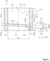
- Figure 6 shows a second connecting part 200 comprising a body 206 extending along a longitudinal axis L, with a front end 202 and a rear end 204, an outer surface 212 and an inner surface 240 comprising a plurality of surfaces 214, 216, 218, 244 and 246.
- the inner surface 240 has a circumferential groove 230.
- the groove 230 is delimited by lateral surfaces 214 and 218 and a groove base 216.
- the groove 230 has a groove width B230 and a groove depth T230 and is suitable for receiving an O-ring or a profile ring.
- the groove 230 extends over the circumference.
- a virtual center line M230 on the groove base 216 has different distances L216 from a fixed point F on the longitudinal axis L, parallel to the longitudinal axis L.
- a maximum distance L216 max in this example is half the groove width B230. In the example, the groove width is 2 mm, so L216 max is 1 mm.
- the first lateral boundary of the groove 230, the surface 214, has different distances L212 parallel to the longitudinal axis L from the rear end 204 of the connecting part 200.
- the minimum distance is designated L212 min and the maximum distance is designated L212 max .
- the second lateral boundary of the groove 230, the surface 218, has different distances L228 parallel to the longitudinal axis L from the front end 202 of the connecting part 200.
- the minimum distance is designated L228 min and the maximum distance is designated L228 max .
- the lateral boundaries - the surfaces 214 and 218 - of the groove 230 therefore have different distances from the rear end 204 and the front end 202, running parallel to the longitudinal axis L.
- the difference between the largest and the smallest distance between one and the same boundary of the groove, the lateral surface 214 or 218 and the rear end 204 or the front end 202 corresponds in this example to half the groove width of 2 mm and is 1 mm here.
- Figure 6a shows as an example the connecting part 200 from Figure 6 with an O-ring 232 in the groove 230.
- the O-ring 232 has a cord thickness Sa of 1.5 mm.
- a virtual center line M232 In the middle of the cord is a virtual center line M232.
- the O-ring 232 extends over the circumference in the groove 230.
- a virtual center line M232 has different distances L216a parallel to the longitudinal axis L from a fixed point F on the longitudinal axis L.
- the maximum distance L216a max in this example is 2/3 of the cord thickness Sa.
- the cord thickness Sa is 1.5 mm, so the maximum distance L216a max is 1 mm.
- the outer surface of the O-ring 232 facing toward the rear end 204 has different distances L212a parallel to the longitudinal axis L from the rear end 204.
- the minimum distance is designated L212a min and the maximum distance is designated L212a max .
- the outer surface of the O-ring 232 facing toward the front end 202 has different distances L228a from the front end 202 parallel to the longitudinal axis L.
- the minimum distance is designated L228a min and the maximum distance is designated L228a max .
- the respective outer surfaces of the O-ring 232 facing the nearer end thus have different axial distances from the rear end 204 and the front end 202 parallel to the longitudinal axis L.
- the difference between the largest and the smallest distance between the outer surface of the O-ring 232 facing the rear end 204 and the rear end 204 and the difference between the largest and the smallest distance between the outer surface of the O-ring 232 facing the front end 202 and the front end 202 corresponds in this example to 2/3 of the cord thickness Sa, here 1 mm.
- Figure 7 shows an example of a first connecting part 100 which is inserted into the connecting part 200 of Figure 6a can be inserted or joined. It comprises a body 106 extending along a longitudinal axis L, with a front end 102 and a rear end 104, with an outer surface 110 comprising a plurality of surfaces 112, 122, 124, 126 and 128, and an inner surface 140.
- An opening 138 extends between the front end 102 and the rear end 104.
- At the rear end 104 there is a chamfer 142 which facilitates the insertion of the connecting part 100 into the opening 238 of the connecting part 200.
- flange 125 which is bounded by the surfaces (outer surfaces) 122, 124 and 126.
- the rear end 104 has an outer surface 108.
- the outer surface 122 of the flange 125 can be used as an axial stop or for positioning axially to the longitudinal axis L, for example in the Figure 6a shown connecting part 200.
- the outer surface 112 can serve for centering radially to the longitudinal axis L, for example, when the connecting part is in the Figure 6 shown connecting part 200 is used.
- the connecting part 100 has a continuous opening 138 with an inner surface 140 along the longitudinal axis L. A fluid can flow through this opening 138 when installed.
- the Figures 8a and 8b show an example of the connection from the first connecting part 100 of Figure 7 and the second connecting part 200 Figure 6a in different states.
- the O-ring 132 doesn't have to be deformed along its entire circumference at the beginning of the joining process; instead, it starts at one point and then "wanders" along the circumference. This reduces the required force and facilitates mating.
- Figure 8b shows, by way of example, the fully joined or nested connecting parts 100 and 200.
- the connection point or line is sealed by nesting the first connecting part 100 into the second connecting part 200 and the O-ring 132 in combination with the surface 112, which is an outer surface, for a fluid that can flow through the inner openings 138 and 238.
- the connecting parts 100 and 200 are aligned radially to the longitudinal axis L via a close tolerance, for example a fit H7/h6 or H7/h7 according to DIN ISO 286, the inner surface 246, which is an inner surface, with the diameter D246 to the surface 112, which is an outer surface, with the diameter D112.
- the axial alignment of the connecting parts relative to the longitudinal axis L is achieved by contact between the surface 122 of the first connecting part 100 and the surface 222 of the second connecting part 200.
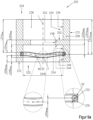
- Figure 9 shows, by way of example, a second connecting part 200 comprising a body 206 extending along a longitudinal axis L, with a front end 202 and a rear end 204, with an outer surface 212 and an inner surface 240 comprising a plurality of surfaces 214, 216, 218, 244, 246, 250, 252, 254 and 256.
- the inner surface 240 has a circumferential groove 230.
- the groove 230 is defined by lateral surfaces 214 and 218 as well as the groove base 216.
- the groove 230 has a groove width B230 and a groove depth T230 and is suitable for receiving an O-ring or a profile ring.
- the groove 230 extends over the circumference.
- the center line M230 has different distances L216 around the perimeter of a fixed point F on the longitudinal axis L.
- the maximum distance L216 max is half the groove width B230.
- the groove width is 2 mm, so L216 max is 1 mm.
- the second lateral boundary of the groove 230, the surface 218, has different distances L228 parallel to the longitudinal axis L from the front end 202 of the connecting part 200.
- the minimum distance is designated L228 min and the maximum distance is designated L228 max .
- the minimum and maximum distances are each present twice here.
- the first lateral boundary of the groove 230, the surface 214 has different distances L212 parallel to the longitudinal axis L to the rear end 204, different distances L220 to the surface 254 of the flange 248 and different distances L224 to the surface 250 of the flange 248.
- the Figure 9 The minimum distances between L212, L224, and L220 shown are labeled L212 min , L224 min , and L220 min , and the maximum distances are labeled L212 max , L224 max , and L220 max . The minimum and maximum distances are each shown twice.
- the lateral boundaries - the surfaces 214 and 218 - of the groove 230 therefore have different distances from the rear end 204 and the front end 202, running parallel to the longitudinal axis L.
- the difference between the largest and the smallest distance between one and the same boundary of the groove, the lateral surface 214, 218 and the rear end 204 or the front end 202 or a surface 250 or 254 of the flange 248 corresponds, for example, to half the groove width of, for example, 2 mm and is 1 mm here.
- the surface 254 of the flange 248 can be used as an axial stop or for positioning axially to the longitudinal axis L, for example in the Figure 10 shown connecting part 100.
- the inner surfaces 244 and 246 can serve for centering radially to the longitudinal axis L, if the connecting part 200 is inserted, for example, into the Figure 10 shown connecting part (100) is inserted.
- Figure 9a shows as an example the connecting part 200 from Figure 9 with an O-ring 232 in the groove 230.
- the O-ring 232 has a cord thickness Sa of 1.5 mm.
- a virtual center line M232 In the middle of the cord is a virtual center line M232.
- the O-ring 232 extends over the circumference in the groove 230.
- a virtual center line M232 has different distances L216a parallel to the longitudinal axis L from a fixed point F on the longitudinal axis L.
- the maximum distance L216a max in this example is 2/3 of the cord thickness Sa.
- the cord thickness Sa is 1.5 mm, so the maximum distance L216a max is 1 mm.
- the outer surface of the O-ring 232 facing toward the rear end 204 has different distances L212a from the rear end 204 parallel to the longitudinal axis L.
- the minimum distance is designated L212a min and the maximum distance is designated L212a max .
- the outer surface of the O-ring 232 facing toward the front end 202 has different distances L228a from the front end 202 parallel to the longitudinal axis L.
- the minimum distance is designated L228a min and the maximum distance is designated L228a max .
- the respective outer surfaces of the O-ring 232 facing the nearer end thus have different axial distances from the rear end 204 and the front end 202 parallel to the longitudinal axis L.
- the difference between the largest and the smallest distance between the outer surface of the O-ring 232 facing the rear end 204 and the rear end 204 and the difference between the largest and the smallest distance between the outer surface of the O-ring 232 facing the front end 202 and the front end 202 corresponds in this example to 2/3 of the cord thickness Sa, here 1 mm.
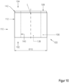
- Figure 10 shows an example of a first connecting part 100 which is inserted into the connecting part 200 of Figure 9a can be inserted or joined. It comprises a body 106 which extends along a longitudinal axis L, with a front end 102 and a rear end 104, with an outer surface 110, with a surface 112 and an inner surface 140. An opening 138 extends between the front end 102 and the rear end 104. At the rear end 104 there is a chamfer 142 which facilitates the insertion of the connecting part 100 into the opening 238 of the connecting part 200.
- the connecting part 100 has a continuous opening 138 with an inner surface 140 along the longitudinal axis L. A fluid can flow through this opening 138 when installed.
- the O-ring 232 is just beginning to make contact with the surface of the chamfer 142 at two points (shown on the left and right).
- the O-ring 232 does not have to be deformed over its entire circumference at the beginning of the joining process; instead, it begins here at two points located opposite each other on the circumference.
- the deformation occurs gradually over the entire circumference, with the points then "migrating" along the circumference. This reduces the required force and facilitates insertion.
- This is an advantage over the Figures 8a and 8b shown figures is that the risk of jamming is reduced by the O-ring hitting the chamfer 142 at two points.
- the disadvantage is that with an increasing number of contact points at the beginning of the joining process, more force is required for the joining.
- Figure 11b shows, by way of example, the fully joined or nested connecting parts 100 and 200.
- the connection point or line is sealed by the nesting of the first connecting part 100 into the second connecting part 200 and the O-ring 232 in combination with the outer surface 112 for a fluid that can flow through the inner openings 138 and 238.
- the connecting parts 100 and 200 are aligned radially to the longitudinal axis L via a close tolerance of the inner surface 246 with a diameter D246 to the outer surface 112 with an outer diameter D112.
- the axial alignment of the connecting parts relative to the longitudinal axis L is achieved by contact between the surface 108 at the rear end 104 of the first connecting part 100 and the surface 254 of the flange 248 of the second connecting part 200.
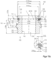
- Figure 12 shows a first connecting part 100 comprising a body 106 extending along a longitudinal axis L, having a front end 102 and a rear end 104, with an outer surface 110 comprising a plurality of surfaces 108, 112, 114, 116, 118, 120, 122, 124, 126 and 128.
- the outer surface 110 has a circumferential groove 130.
- the groove is delimited by lateral surfaces 114 (facing the rear end 104) and 118 (facing the front end) as well as a groove base 116.
- the groove 130 has a groove width B130 and a groove depth T130 and is suitable for receiving an O-ring or a profile ring.
- the groove 130 extends over the circumference. Different groove shapes, as shown for example in the Figures 1a to 1c are shown.
- flange 125 which is bounded by the surfaces 122, 124 and 126.
- the surface 122 of the flange 125 can be used as an axial stop or for positioning axially to the longitudinal axis L, for example in the Figure 13 shown connecting part (200).
- the outer surfaces 112 and 120 can serve for centering radially to the longitudinal axis L when the connecting part 100 is inserted, for example, into the Figure 13 shown connecting part 200 is used.
- the connecting part 100 has a continuous opening 138 with an inner surface 140 along the longitudinal axis L. A fluid can flow through this opening 138 when installed.
- the rear end 104 has an outer surface 108.
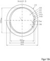
- the Figure 12a shows the view A, i.e. the view from the rear end 104, of the connecting part 100 from Figure 12 .
- the contours of surface 124 of flange 125 and surface 112 of outer surface 110 are shown as examples.
- the contour of inner surface 140 is also shown as an example.
- Surface 122 of flange 125 is also shown as an example.
- the contour of flange 125 and surface 124 is a circle with a diameter D124.
- the contour of inner surface 140 is also a circle with a diameter D140. However, they could also have almost any other shape.
- the contour of surface 112 has a minimum distance D112 min and a maximum distance D112 max extending through the longitudinal axis in the direction perpendicular to the longitudinal axis L.
- the maximum distance D112 max is also in Figure 12 shown.
- the contour is exemplary elliptical.
- the Figure 12b shows the section BB of the connecting part from Figure 12 .
- the contours of the outer surface 110, the surface 124 of the flange 125, the surface 120, and the surface of the groove bottom 116 are shown.
- the contour of the inner surface 140 is also shown.
- the surface 122 of the flange 125 is also shown.
- the contour of the flange 125 or the surface 124 is a circle with a diameter D124.
- the contour of the inner surface 140 is also a circle with a diameter D140. However, they could also have almost any other shape.
- the contour of the surface 120 has a smallest distance D120 min and a largest distance D120 max extending through the longitudinal axis in the direction perpendicular to the longitudinal axis L.
- the contour of the surface of the groove base 116 has a smallest distance D116 min and a largest distance D116 max extending through the longitudinal axis in the direction perpendicular to the longitudinal axis L.
- the distances D120 and D116 extending through the longitudinal axis L and perpendicular to the longitudinal axis L between the opposite contour sections of the surfaces 120 and 116 are therefore not constant along the circumference. The distances vary here on the circumference.
- the maximum distances D116 max and D120 max are also in Figure 12 shown.
- the diameter D124 is 24 mm and the diameter D140 is 12 mm.
- the smallest distances D112 min and D120 min in this example are 20 mm, and the largest distances D112 max and D120 max in this example are 21 mm. The difference between the smallest and largest distance is therefore 1 mm, and the largest distance is 5% larger than the smallest distance.
- the smallest distance D116 min in this example is 18 mm, and the largest distance D116 max in this example is 19 mm. The difference between the smallest and largest distance is therefore 1 mm, and the largest distance is approximately 5.5% larger than the smallest distance.
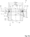
- Figure 12c shows the connecting part Figure 12 with an O-ring 132 in the groove (130).
- the O-ring 132 has a cross section Sa of 1.5 mm.
- a virtual centerline M132 is located in the middle of the cross section.
- the O-ring 132 extends circumferentially in the groove 130.
- the groove depth T130 is 1 mm and the groove width B130 is 2 mm.
- the inner side of the O-ring 132 directed towards the longitudinal axis L is located with its innermost surface 132i at the groove bottom 116.
- the outer side of the O-ring 132 projects with the outermost surface 132a beyond the outer surfaces 112 and 120.
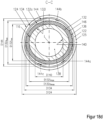
- the Figure 12d shows the section CC of the connecting part from Figure 12c seen from the rear end 104. This view also shows a section through the O-ring 132.
- the contours of surface 124 of flange 125 are shown from the outer surface 110.
- the contour of the inner surface 140 is also shown.
- Surface 122 of flange 125 is also shown.
- the contour of flange 125 or surface 124 is a circle with a diameter D124.
- the contour of the inner surface 140 is also a circle with a diameter D140. However, they could also have almost any other shape.
- the contour of the innermost surface 132i of the O-ring 132 has, in the direction perpendicular to the longitudinal axis L, a smallest distance D132i min and a largest distance D132i max extending through the longitudinal axis.
- the contour of the outermost surface 132a of the O-ring 132 has a smallest distance D132a min and a largest distance D132a max extending through the longitudinal axis in the direction perpendicular to the longitudinal axis L.
- the distances D132i and D132a extending through the longitudinal axis L and perpendicular to the longitudinal axis L between the opposite contour sections of the surfaces 132i and 132a of the O-ring 132 are therefore not constant along the circumference.
- the distances vary here on the circumference.
- the largest distances D132i max and D132a max are also in Figure 12c shown.
- the smallest distance D132i min in this example is 18 mm and the largest distance D132i max in this example is 19 mm, so the difference between the smallest and the largest distance is 1 mm and the largest distance is approx. 5.5% larger than the smallest distance. Since the O-ring's cross section Sa in this example is 1.5 mm, the difference of 1 mm is equal to 2/3 of the cross section Sa.
- the smallest distance D132a min is 21 mm
- the largest distance D132a max is 22 mm.
- the difference between the smallest and largest distances is therefore 1 mm, and the largest distance is approximately 4.7% larger than the smallest distance. Since the O-ring's cross section Sa is 1.5 mm in this example, the difference of 1 mm is equal to 2/3 of the cross section Sa.
- the contours of the outer surfaces 112 and 120 can also have a circular shape with a constant diameter D112 and D120 along the circumference; thus, there need not be a maximum and a minimum distance. However, it is then a condition that the smallest distance D132a min extending through the longitudinal axis L and perpendicular to the longitudinal axis L between the opposite contour sections of the surfaces 132a of the O-ring is greater than the two diameters D112 and D120.
- Figure 13 shows a sectional view of an exemplary second connecting part 200, into which, for example, the connecting part 100 from Figure 12c It comprises a body 206 extending along a longitudinal axis L, having a front end 202 and a rear end 204, with an outer surface 212 and inner surfaces 242 and 244.
- An opening 238 extends between the front end 202 and the rear end 204.
- a surface 222 which serves as a stop surface for the stop surface 122 of the connecting part 100 made of Figure 12c serves.
- the opening 238 has, as seen from the front end 202, a second section with the inner surface 242 and a third section with the inner surface 244.
- a body edge 242a is formed in the transition from the outer surface 222 to the inner surface 242.
- a body edge 242b is formed at least over a partial circumference in the transition from the inner surface 242 to the inner surface 244.
- the body edges 242a and 242b can, for example, be rounded, e.g., provided with a radius. At least In this example, it is designed as a chamfer over a partial circumference, i.e., oblique to the longitudinal axis and here, for example, with an angle ⁇ of 20° to the longitudinal axis included between the longitudinal axis L and the surface 242.
- the body edge 242b has different distances L242b to the front end 202 parallel to the longitudinal axis L.
- the greatest distance is designated L242b max and the smallest distance L242b min .
- the inner surface 242 of the chamfer thus has different distances along the circumference between the body edges 242a and 242b, both parallel to the longitudinal axis L and parallel to the surface 242.
- the inner contour of the first section with the inner surface 246, which consists only of the body edge 242a, is a circle with a diameter D246.
- the inner contour of the third section with the inner surface 244 has a smallest distance D244 min extending through the longitudinal axis L in the direction perpendicular to the longitudinal axis L, which in Figure 13 and 13b shown, and a maximum distance D244 max , which is Figure 13a and 13b
- the second section, which forms the transition between the first and the third section, has a chamfer with the inner surface 242 over at least a partial area of the circumference, as shown in Figure 13 and 13b
- the smallest distance D244 min is smaller than the diameter D246.
- the largest Distance D244 max is here equal to diameter D246, as in Figure 13a and 13b shown, but could also be smaller than D246.
- an outer surface 134 is located on the outer surface 110.
- the section with the outer surface 134 has a diameter D134 that is larger than the diameter D120 of the section with the outer surface 120.
- the outer surface 134 serves for centering radially to the longitudinal axis L, when the connecting part is inserted, for example, into the Figure 16a shown connecting part 200 is used.
- the greatest distance extending perpendicular to the longitudinal axis between the longitudinal axis L and one or more points or sections of the contour of surface 134 is greater than the greatest distance extending perpendicular to the longitudinal axis between the longitudinal axis L and one or more points or sections of the contour of surface 120.
- the O-ring 132 has a cord thickness Sa of, for example, 1.5 mm.
- a virtual centerline M132 is located in the middle of the cord.
- the O-ring 132 extends circumferentially in the groove 130.
- the Figure 15d shows the section CC of the connecting part from Figure 15c seen from the rear end 104. This view also shows a section through the O-ring 132.
- the contours of surface 124 of flange 125 and surface 134 of outer surface 110 are shown.
- the contour of inner surface 140 is also shown.
- Surface 122 of flange 125 and surface 136 are also shown.
- the contour The contour of surface 124 is a circle with a diameter of D124
- the contour of surface 134 is a circle with a diameter of D134.
- the contour of inner surface 140 is also a circle with a diameter of D140. However, they can also have almost any other shape.
- the contour of the innermost surface 132i of the O-ring 132 has a smallest distance D132i min and a largest distance D132i max extending through the longitudinal axis L in the direction perpendicular to the longitudinal axis L.
- the contour of the outermost surface 132a of the O-ring 132 has, in the direction perpendicular to the longitudinal axis L, a smallest distance D132a min and a largest distance D132a max extending through the longitudinal axis L.
- the smallest distance D132i min of the innermost surface 132i is 18 mm
- the largest distance D132i max of the innermost surface 132i is 19 mm.
- the difference between the smallest and largest distances is therefore 1 mm, and the largest distance is approximately 5.5% larger than the smallest distance.
- the cross-sectional area Sa of the O-ring is 1.5 mm in this example, the difference of 1 mm is 2/3 of the cross-sectional area Sa.
- the smallest distance D132a min of the outermost surface 132a is 21 mm
- the largest distance D132a max of the outermost surface 132a is 22 mm.
- the difference between the smallest and largest distances is therefore 1 mm, and the largest distance is approximately 4.7% larger than the smallest distance. Since the O-ring's cross section Sa is 1.5 mm in this example, the difference of 1 mm is 2/3 of the cross section Sa.
- the smallest distance D132a min extending through the longitudinal axis and perpendicular to the longitudinal axis L between the opposite contour sections of the surfaces 132a of the O-ring must be greater than the diameter D120.
- the greatest distance D132a max extending through the longitudinal axis and perpendicular to the longitudinal axis L between the opposite contour sections of the surfaces 132a of the O-ring must be greater than the greatest distance D112 max .
- Figure 16 shows, by way of example, a sectional view of a second connecting part 200, into which, for example, the connecting part 100 from Figure 15c It comprises a body 206 extending along a longitudinal axis L, having a front end 202 and a rear end 204, with an outer surface 212 and inner surfaces 242, 244 and 246.
- An opening 238 extends between the front end 202 and the rear end 204.
- a surface 222 which serves as a stop surface for the stop surface 122 of the connecting part 100 made of Figure 15 serves.
- the opening 238 has, as viewed from the front end 202, a first section with the inner surface 246, a second section with the inner surface 242, and a third section with the inner surface 244.
- a body edge 242a is formed at the transition from the inner surface 246 to the inner surface 242.
- a body edge 242b is formed over the entire circumference at the transition from the inner surface 242 to the inner surface 244.
- the body edges 242a and 242b can be rounded, for example, provided with a radius.
- the inner surface 242 is therefore located between the inner surfaces 246 and 244.
- a chamfer is formed along the entire circumference, for example, obliquely to the longitudinal axis L and here, for example, with an angle ⁇ of 20° to the longitudinal axis included between the longitudinal axis L and the surface 242, and realizes the transition between the first section with the inner surface 246 and the third section with the inner surface 244.
- the body edge 242b has different distances L242b from the front end 202 parallel to the longitudinal axis L. The greatest distance is designated L242b max and the smallest distance L242b min .
- the inner surface 242 of the chamfer thus has different distances along the circumference between the body edges 242a and 242b, both parallel to the longitudinal axis L and parallel to the surface 242.
- the distances of the body edges 242b to the front end 202 parallel to the longitudinal axis are greater than the distance of the body edge 242a to the front end 202.
- the Figure 16a shows the sectioned view CC of the same connecting part 200, which is for viewing in Figure 16 is rotated by 90° around the longitudinal axis L. It should once again clarify the formation of the surface 242, otherwise the description of Figure 16 .
- the Figure 16b shows the view B of the second connecting part 200 from Figure 16 , i.e., viewed from the front end 202.
- the outer contour of the outer surface 212 and the inner contours of the inner surfaces 242, 244, and 246, as well as the body edges 242a and 242b, are visible.
- the outer contour 212 is a circle with a diameter D212, but could also have a different shape. It can be seen that the inner surface 242 of the chamfer extends over the entire circumference in this exemplary embodiment.
- the inner contour of the first section with the inner surface 246 is a circle with a diameter D246.
- the inner contour of the third section with the inner surface 244 has a smallest distance D244 min extending through the longitudinal axis in the direction perpendicular to the longitudinal axis L, which in Figure 16a and 16b shown and largest distance D244 max , which is in Figure 16 and 16b
- the second section, which forms the transition between the first and third sections, has a chamfer with the inner surface 242 over the entire circumference, as shown in the Figures 16 , 16a and 16b
- the largest distance D244 max is smaller than the diameter D246, as shown in Figure 16 and 16b shown.
- the diameter D246 23 mm
- the largest distance D244 max 21.2 mm
- the smallest distance D244 min 20.2 mm.
- the difference between the largest distance D244 max and the smallest distance D244 min is therefore 1 mm, or just under 5% of the largest distance.
- the difference between the maximum distance L242b max and the minimum distance L242b min in this example is 1.1 mm.
- the diameter D246 has a particularly tight tolerance, for example with a fit H 7 (0 to +21 ⁇ m) according to DIN ISO 286. This ensures radial alignment or centering to the longitudinal axis L between the first connecting part 100 and the second connecting part 200.
- the outer surface 134 of the first connecting part 100 and the inner surface 246 of the second connecting part 200 are arranged at a closely tolerated distance from one another and at least partially touch one another.
- the Figures 17a and 17b show an example of the connection from the first connecting part 100 from Figure 15 or 15c and the second connecting part 200 made of Figure 16 in different states.
- the O-ring 132 initially only comes into contact with the inner surface 242 of the chamfer 242 and with the body edge 242b at two points 300.
- the O-ring 132 does not have to be deformed over its entire circumference right at the beginning of the joining process; instead, it begins initially in two places, i.e., on a partial circumference, and depending on the joining state, the deformation gradually occurs over the entire circumference. This reduces the required force and facilitates insertion.
- Figure 17b shows the fully joined or nested connecting parts 100 and 200.
- the connection point or line is sealed by the nesting of the first connecting part 100 into the second connecting part 200 and the O-ring 132 in combination with the inner surface 240 for a fluid that can flow through the inner openings 138 and 238.
- the connecting parts 100 and 200 are radially aligned to the longitudinal axis L via a close tolerance, e.g. a fit h6/H7, according to DIN ISO 286, of the inner surface 246 with the diameter D246 (H7, from 0 to +21 ⁇ m) to the outer surface 134 with the diameter D134 (h6, from -13 to 0 ⁇ m).
- a fit h7/H7 according to DIN ISO 286, of the inner surface 246 with The diameter D246 (H7, from 0 to +21 ⁇ m) to the outer surface 134 with the diameter D134 (h7, from -21 to 0 ⁇ m) is possible.
- the axial alignment of the connecting parts 100 and 200 relative to the longitudinal axis L is achieved by the contact of the surface 122 of the first connecting part 100 and the surface 222 of the second connecting part 200.
- Figure 18 shows a first connecting part 100 comprising a body 106 extending along a longitudinal axis L, having a front end 102 and a rear end 104, with an outer surface 110 comprising a plurality of surfaces 112, 114, 116, 118, 120, 122, 124, 126, 128, 134, 136, 144 and 146.
- the outer surface 110 has a circumferential groove 130.
- the groove is defined by lateral surfaces 114 and 118 and a groove base 116.
- the groove 130 has a groove width B130 and a groove depth suitable for receiving an O-ring or a profile ring.
- the groove 130 extends over the circumference. Different groove shapes, as shown for example in the Figures 1a to 1c are shown.
- flange 125 which is bounded by the surfaces 122, 124 and 126.
- the section with the surface 144 has a diameter D144 that is greater than the greatest distance D120 max of the surface 120 extending through the longitudinal axis L in the direction perpendicular to the longitudinal axis L.
- the outer surface 144 there are three grooves or recesses 144a, 144b and 144c, whereby only two grooves are visible in this view.
- the grooves extend parallel to the longitudinal axis L. These ensure, for example, in interaction with the lugs of the connecting part 200 made of Figure 19 the positioning rotationally to the longitudinal axis L along the circumference of the connecting parts to each other.
- a surface 134 which acts as a centering surface, and a surface 136.
- the section with the surface 134 has a diameter D134 that is greater than the largest distance D120 max of the surface 120 and greater than the diameter D144 of the section of the surface 144.
- the surface 134 serves for centering radially to the longitudinal axis L when the connecting part 100 is inserted, for example, into the Figure 19a shown connecting part 200 is used.
- the stop surface 122 serves as an axial stop or for positioning axially to the longitudinal axis L, for example in the Figure 19a shown connecting part 200.
- the connecting part 100 has a continuous opening 138 with an inner surface 140 along the longitudinal axis L. A fluid can flow through this opening 138 when installed.
- the Figure 18a shows view A, i.e. the view from the rear end 104, of the connecting part Figure 18 .
- the contours of surface 124 of the flange 125, surface 120, surface 112, surface 144 and surface 134, which functions as a centering surface are shown.
- the contour of the inner surface 140 is also shown.
- surface 122 of the flange 125, surface 146 and surface 136 are also shown.
- the contour of surface 124 is a circle with a diameter D124.
- the contour of surface 112 is also a circle with a diameter D112.
- the contour of the outer surface 144 is also a circle and here, for example, has three grooves 144a, 144b and 144c.
- the contour of surface 134 is a circle with a diameter D134.
- the contour of the inner surface 140 is also a circle with a diameter D140.
- the contours can also have almost any other shape.
- the contour of the surface 120 has a smallest distance D120 min and a largest distance D120 max extending through the longitudinal axis in the direction perpendicular to the longitudinal axis L.
- the Figure 18b shows the section BB of the connecting part from Figure 18 .
- the contours of surface 124 of the flange 125, surface 120, surface 144, surface 134 and the surface of the groove bottom 116 are shown.
- the contour of the inner surface 140 is also shown.
- surface 122 of the flange 125 is shown.
- Surfaces 136 and 146 are also shown.
- the contour of surface 124 is a circle with a diameter D124
- the contour of surface 134 is a circle with a diameter D134.
- the contour of the outer surface 144 is also a circle and here, for example, has three grooves 144a, 144b and 144c.
- the contour of the inner surface 140 is also a circle with a diameter D140. However, they can also have almost any other shape.
- the largest distance extending perpendicular to the longitudinal axis between the longitudinal axis L and one or more points or sections of the contour of the surface 134 is greater than the largest distance extending perpendicular to the longitudinal axis extending distance between the longitudinal axis L and one or more points or sections of the contour of the surfaces 112, 120 and 144.
- the contour of the surface 120 has a smallest distance D120 min and a largest distance D120 max extending through the longitudinal axis in the direction perpendicular to the longitudinal axis L.
- the contour of the surface of the groove base 116 has a smallest distance D116 min and a largest distance D116 max extending through the longitudinal axis in the direction perpendicular to the longitudinal axis L.
- the diameter D112 20 mm
- the diameter D124 24 mm
- the diameter D140 12 mm
- the diameter D144 23 mm
- the diameter D 134 23.5 mm.
- the diameter D134 has particularly close tolerances, for example with a fit h6 (-13 to 0 ⁇ m) or h7 (-21 to 0 ⁇ m) according to DIN ISO 286.
- the smallest distance D116 min in this example is 18 mm and the largest distance D116 max in this example is 19 mm, so the difference between the smallest and the largest distance is 1 mm and the largest distance is approx. 5.5% larger than the smallest distance.
- the groove 130 On one side of the groove, here on the side of the surface 114, the groove 130 has different distances T112 extending axially to the longitudinal axis L between the groove bottom 116 and the surface 112 along the circumference.
- the maximum distance D120 max must be greater than the maximum distance D116 max and the diameter D112, which must be greater than the maximum distance D116 max . [D120 max > D112 > D116 max ].
- Figure 18c shows as an example the connecting part 100 from Figure 18 with an O-ring 132 in the groove 130.
- the O-ring 132 has a cord thickness Sa of 1.5 mm.
- a virtual center line M132 is located in the middle of the cord.
- the O-ring 132 extends over the circumference in the groove 130.
- the inner side of the O-ring, directed towards the longitudinal axis L, is located with its innermost surface 132i at the groove bottom 116.
- the outer side of the O-ring 132 protrudes beyond the outer surfaces 112 and 120 with the outermost surface 132a.
- the outer side of the O-ring 132 does not protrude beyond the outer surfaces 144 and 134 with its outermost surface 132a. It is advantageous if it also does not protrude beyond the bottoms of the grooves 144a, 144b and 144c.
- the Figure 18d shows the section CC of the connecting part 100 from Figure 18c seen from the rear end 104. This view also shows a section through the O-ring 132.
- the contours of surface 124 of flange 125, surface 134, and surface 144 of outer surface 110 are shown.
- the contour of inner surface 140 is also shown.
- Surface 122 of flange 125 and surface 136 are also shown.
- the contour of surface 124 is a circle with a diameter D124
- the contour of surface 134 is a circle with a diameter D134.
- the contour of outer surface 144 is also a circle and, in this example, has three grooves 144a, 144b, and 144c.
- the contour of inner surface 140 is also a circle with a diameter D140. However, they can also have almost any other shape.
- the contour of the innermost surface 132i of the O-ring 132 has, in the direction perpendicular to the longitudinal axis L, a smallest distance D132i min and a largest distance D132i max extending through the longitudinal axis.
- the contour of the outermost surface 132a of the circular ring 132 has, in the direction perpendicular to the longitudinal axis L, a smallest distance D132a min and a largest distance D132a max extending through the longitudinal axis.
- the smallest distance D132i min is 18 mm
- the largest distance D132i max is 19 mm.
- the difference between the smallest and largest distance is therefore 1 mm, and the largest distance is approximately 5.5% larger than the smallest distance. Since the O-ring's cross section Sa is 1.5 mm, the difference of 1 mm is 2/3 of the cross section Sa.
- the smallest distance D132a min is 21 mm
- the largest distance D132a max is 22 mm.
- the difference between the smallest and largest distances is therefore 1 mm, and the largest distance is approximately 4.7% larger than the smallest distance. Since the O-ring's cross section Sa is 1.5 mm in this example, the difference of 1 mm is 2/3 of the cross section Sa.
- Figure 19 shows a sectional view of a second connecting part 200, into which, for example, the connecting part 100 from Figure 18c It comprises a body 206 extending along a longitudinal axis L, having a front end 202 and a rear end 204, having an outer surface 212 and the inner surfaces 242, 244, 246 and 258.
- An opening 238 extends between the front end 202 and the rear end 204.
- a surface 222 which serves as a stop surface for the stop surface 122 of the connecting part 100 made of Figure 18 serves.
- the opening 238 has, as viewed from the front end 202, a first section with the inner surface 246, a fourth section with the inner surface 258, a second section with the inner surface 242, and a third section with the inner surface 244.
- a body edge 242a is formed at the transition from the inner surface 258 to the inner surface 242.
- a body edge 242b is formed over the entire circumference at the transition from the inner surface 242 to the inner surface 244.
- the body edges 242a and 242b can, for example, be rounded, e.g., provided with a radius.
- the inner surface 242 is therefore located between the inner surfaces 258 and 244.
- a chamfer is formed along the entire circumference, for example, obliquely to the longitudinal axis L and here, for example, with an angle ⁇ of 20° to the longitudinal axis included between the longitudinal axis L and the surface 242, and realizes the transition between the fourth section with the inner surface 258 and the third section with the inner surface 244.
- the body edge 242b has different distances L242b from the front end 202 parallel to the longitudinal axis L, the greatest distance being designated L242b max and the smallest distance L242b min .
- the inner surface 242 of the chamfer thus has different distances along the circumference between the body edges 242a and 242b, both parallel to the longitudinal axis L and parallel to the surface 242.
- the distances of the body edges 242b to the front end 202 parallel to the longitudinal axis L are greater than the distance of the body edge 242a to the front end 202.
- the Figure 19a shows the sectioned view CC of the same connecting part 200, which is for viewing in Figure 19 is rotated by 90° around the longitudinal axis L. It should once again clarify the formation of the surface 242, otherwise the description of Figure 19 .
- the projections 258a and 258c can also be seen on the inner surface 258.
- the Figure 19b shows view B of the second connecting part from Figure 19a , i.e., viewed from the front end 202.
- the outer contour of the outer surface 212 and the inner contours of the inner surfaces 242, 244, 246, and 258 with the projections 258a, 258b, and 258c, as well as the body edges 242a and 242b, can be seen.
- the outer contour 212 is a circle with a diameter D212, but could also have a different shape. It can be seen that the inner surface 242 of the chamfer extends over the entire circumference in this exemplary embodiment.
- the inner contour of the first section with the inner surface 246 is a circle with a diameter D246.
- the inner contour of the fourth section with the inner surface 258 is a circle with a diameter D258 with the projections or noses 258a, 258b and 258c, which are distributed and designed along the circumference of the inner surface in such a way that they engage with the grooves or depressions 144a, 144b and 144c when plugged together and in the plugged-together state with the connecting part 100.
- the inner contour of the third section with the inner surface 244 has a smallest distance D244 min extending through the longitudinal axis in the direction perpendicular to the longitudinal axis L, which in Figure 19 and 19b shown, and largest distance D244 max , which is in Figure 19a and 19b
- the second section, which forms the transition between the fourth and the third section, shows a chamfer with the inner surface 242 over the entire circumference, as shown in the Figures 19 , 19a and 19b
- the largest distance D244 max is smaller than the diameter D246, as shown in Figure 19a and 19b shown.
- the diameter D246 23 mm
- the largest distance D244 max 21.2 mm
- the smallest distance D244 min 20.2 mm.
- the difference between the largest distance D244 max and the smallest distance D244 min is therefore 1 mm, or just under 5% of the largest distance.
- the difference L243 between the maximum distance L242b max and the minimum distance L242b min is 1.1 mm.
- the diameter D246 has a particularly tight tolerance, for example with a fit H 7 (0 to +21 ⁇ m) according to DIN ISO 286. This ensures radial alignment or centering to the longitudinal axis L between the first connecting part (100) and the second connecting part 200.
- the outer surface 134 of the first connecting part 100 and the inner surface 246 of the second connecting part 200 are arranged at a closely tolerated distance from one another and at least partially touch one another.
- the Figures 20a and 20b show an example of the connection from the first connecting part 100 from Figure 18c and the second connecting part 200 Figure 19 in different joined states.
- the connecting parts are inserted into one another such that the grooves or depressions 144a, 144b and 144c correspond to the lugs or projections 258a, 258b and 258c and are in engagement with one another.
- the first and second connecting parts 100 and 200 can only be inserted or joined into one another in a rotational position relative to the longitudinal axis L, namely when the grooves or depressions correspond to the lugs or projections and are in engagement with one another.
- three projections and depressions are shown. It is particularly advantageous to have an arrangement such as DE 20 2007 005 316 A1 described.
- a recess 258b and a projection 144b are shown which are in engagement with one another, i.e. are arranged opposite one another.
- the O-ring (132) is just beginning to make contact with the inner surface 242 of the chamfer 242 and with the body edge 242b, initially only at two points 300.
- the O-ring 132 does not have to be deformed over its entire circumference right at the beginning of the joining process; instead, it begins initially at two points, i.e., on a partial circumference. Depending on the joining state, the deformation gradually occurs over the entire circumference. This reduces the required force and facilitates insertion.
- Figure 21 shows an example of a nozzle 2 for a plasma torch, which has the features of the connecting part 100 from the Figure 18
- the nozzle has a nozzle bore or nozzle channel 46 at the front end, which constricts a plasma jet.
- the plasma gas that is ionized to generate the plasma jet is the fluid that flows through the interior space 138.
- the plasma jet itself flows through at least a portion of this interior space 138 before exiting through the nozzle channel 46.
- the nozzle has the features of the connecting part 100.
- Figure 18 Of course, all other embodiments shown in the previous figures are also possible.
- a feature is shown here to keep the nozzle size as small as possible.
- the length L112 between the boundary 114 of the groove 130 directed toward the rear end 104 and the rear end 104 with the surface 108 is smaller than the groove width B130. In this case, it amounts to only 40% of the groove width B130.
- Figure 21a shows, by way of example, the same nozzle 2 with an O-ring 132 in the groove 130.
- the nozzle 2 has the features of the connecting part 100 figure 18c
- all other embodiments shown in the previous figures are also possible.
- the length L112a between the surface of O-ring 130 facing the rear end 104 and the rear end 104 with surface 108 is smaller than the groove width B130. In this example, it is only half the groove width B130.
- Such a nozzle 2 with the features according to the invention defined in the claims can also be used, for example, in a laser processing head.
- Figure 22 shows essential components of a plasma torch head. These are at least one electrode 1, a nozzle 2, a nozzle holder 7, and a gas guide 4.
- the electrode is arranged in the inner cavity of the nozzle 2.
- a gas guide 4 for the plasma gas PG which flows through the gas guide 4, then the space between the electrode 1 and the nozzle 2, and finally out of the nozzle opening.
- the nozzle 2 is inserted into the nozzle holder 7.
- the nozzle 2 can have the features of the connecting part 100; all variants shown in the previous figures are possible.
- the nozzle holder 7 can have the features of the connecting part 200.
- all variants shown in the previous figures are possible.
- the nozzle 2 it is also possible for the nozzle 2 to have the features of the second connecting part 200 and the nozzle receptacle 7 of the first connecting part 100.
- the advantages of the invention namely the reduction of the force required during joining, the good alignment parallel and radial to the longitudinal axis L of the connecting parts, and, depending on the design, the rotational positioning to the longitudinal axis L along the circumference of the connecting parts, individually or in any combination, facilitate nozzle replacement.
- the plasma torch head shown here also has a nozzle cap 3 that secures the nozzle 2, a protective cap 5, a gas guide 6 that is located between the protective cap 5 and the nozzle cap 3 and insulates them from each other, and the protective cap holder 8 that holds the protective cap.
- the secondary gas SG flows through openings (not shown) in the gas guide 6, then through the space between the nozzle cap 3 and the nozzle protective cap 5, and finally out of the front opening of the nozzle protective cap 5.
- the nozzle 2 and nozzle cap 3 to consist of one part.
- plasma arc torch heads that are operated without secondary gas. These then generally have no nozzle protective cap or nozzle protective cap holder.
- the example shown is a water-cooled plasma torch head.
- the coolant flows via the coolant supply line WV through the nozzle holder 7, flows through the space 10 between the nozzle holder 7 and the nozzle 2, into the space between the nozzle 2 and the nozzle cap 3, before flowing back through the coolant return line WR.
- the preceding description focused on connecting parts and wear parts for a plasma torch head.
- the plasma torch head can be a plasma cutting head or a plasma welding torch head.
Landscapes
- Engineering & Computer Science (AREA)
- Physics & Mathematics (AREA)
- Mechanical Engineering (AREA)
- Plasma & Fusion (AREA)
- Optics & Photonics (AREA)
- General Engineering & Computer Science (AREA)
- Spectroscopy & Molecular Physics (AREA)
- Geometry (AREA)
- Gasket Seals (AREA)
- Arc Welding In General (AREA)
- Plasma Technology (AREA)
Priority Applications (1)
| Application Number | Priority Date | Filing Date | Title |
|---|---|---|---|
| HRP20250613TT HRP20250613T1 (hr) | 2018-07-27 | 2019-07-24 | Spojni dijelovi za glavu za obradu, namijenjenu toplinskoj obradi materijala, osobito za glavu plazmatskog plamenika |
Applications Claiming Priority (3)
| Application Number | Priority Date | Filing Date | Title |
|---|---|---|---|
| DE102018005914 | 2018-07-27 | ||
| DE102018125772.4A DE102018125772A1 (de) | 2018-07-27 | 2018-10-17 | Verbindungsteil für einen Bearbeitungskopf zur thermischen Materialbearbeitung, insbesondere für einen Plasmabrennerkopf, Laserkopf, Plasma-Laser-Kopf sowie ein Verschleißteil und eine Verschleißteilhalterung und ein Verfahren zum Fügen dieser |
| PCT/DE2019/100680 WO2020020415A1 (de) | 2018-07-27 | 2019-07-24 | VERBINDUNGSTEIL FÜR EINEN BEARBEITUNGSKOPF ZUR THERMISCHEN MATERIALBEARBEITUNG, INSBESONDERE FÜR EINEN PLASMABRENNERKOPF, LASERKOPF, PLASMA-LASER-KOPF SOWIE EIN VERSCHLEIßTEIL UND EINE VERSCHLEIßTEILHALTERUNG UND EIN VERFAHREN ZUM FÜGEN DIESER |
Publications (3)
| Publication Number | Publication Date |
|---|---|
| EP3829807A1 EP3829807A1 (de) | 2021-06-09 |
| EP3829807C0 EP3829807C0 (de) | 2025-03-19 |
| EP3829807B1 true EP3829807B1 (de) | 2025-03-19 |
Family
ID=69148908
Family Applications (1)
| Application Number | Title | Priority Date | Filing Date |
|---|---|---|---|
| EP19752085.1A Active EP3829807B1 (de) | 2018-07-27 | 2019-07-24 | Verbindungsteile für einen bearbeitungskopf zur thermischen materialbearbeitung, insbesondere für einen plasmabrennerkopf |
Country Status (14)
| Country | Link |
|---|---|
| US (2) | US20210316407A1 (https=) |
| EP (1) | EP3829807B1 (https=) |
| JP (1) | JP7295218B2 (https=) |
| KR (1) | KR102836721B1 (https=) |
| CN (1) | CN112789133B (https=) |
| CA (1) | CA3107146A1 (https=) |
| DE (1) | DE102018125772A1 (https=) |
| ES (1) | ES3030702T3 (https=) |
| HR (1) | HRP20250613T1 (https=) |
| HU (1) | HUE071678T2 (https=) |
| MX (1) | MX2021000985A (https=) |
| PL (1) | PL3829807T3 (https=) |
| RU (1) | RU2770169C1 (https=) |
| WO (1) | WO2020020415A1 (https=) |
Families Citing this family (3)
| Publication number | Priority date | Publication date | Assignee | Title |
|---|---|---|---|---|
| FR3100003B1 (fr) * | 2019-08-22 | 2021-09-03 | Safran Aircraft Engines | Système de dépôt laser de métal |
| DE202021000543U1 (de) | 2021-02-15 | 2022-05-18 | VOSS Automotive GmbH | Steckerteil sowie Fluidverbinder mit zumindest einem solchen Steckerteil und zumindest einem Kupplungsteil |
| FR3127798B1 (fr) * | 2021-10-01 | 2023-09-29 | Akwel Sweden Ab | Joint d’étanchéité torique et raccord fluidique pour circuit de transfert de fluide comprenant un tel joint. |
Citations (1)
| Publication number | Priority date | Publication date | Assignee | Title |
|---|---|---|---|---|
| US4649257A (en) * | 1986-05-06 | 1987-03-10 | The Perkin-Elmer Corporation | Gas distribution ring for plasma gun |
Family Cites Families (20)
| Publication number | Priority date | Publication date | Assignee | Title |
|---|---|---|---|---|
| US5893985A (en) * | 1997-03-14 | 1999-04-13 | The Lincoln Electric Company | Plasma arc torch |
| IT1293434B1 (it) * | 1997-07-11 | 1999-03-01 | Elasis Sistema Ricerca Fiat | Dispositivo di tenuta tra due vani soggetti a pressioni diverse, ad esempio in un inietttore di combustibile per motori a comustione |
| RU7359U1 (ru) * | 1997-08-13 | 1998-08-16 | Александр Юрьевич Савиных | Плазмотрон |
| US6199871B1 (en) * | 1998-09-02 | 2001-03-13 | General Electric Company | High excursion ring seal |
| JP2005118816A (ja) * | 2003-10-16 | 2005-05-12 | Koike Sanso Kogyo Co Ltd | プラズマトーチ用のノズル |
| AT502419B1 (de) * | 2005-09-09 | 2007-08-15 | Fronius Int Gmbh | Schweissbrenner und verfahren zur prozesssteuerung einer schweissanlage |
| UA82584C2 (en) * | 2006-07-10 | 2008-04-25 | Анатолий Тимофеевич Неклеса | Electric-arc plasmatron |
| US8089025B2 (en) * | 2007-02-16 | 2012-01-03 | Hypertherm, Inc. | Gas-cooled plasma arc cutting torch |
| CN101251192A (zh) * | 2007-02-23 | 2008-08-27 | 卡罗克密封技术公司 | 开口式轴承隔离件以及用于组装密封件的方法 |
| DE102009060849A1 (de) * | 2009-12-30 | 2011-07-07 | Kjellberg Finsterwalde Plasma und Maschinen GmbH, 03238 | Düse für einen flüssigkeitsgekühlten Plasmabrenner sowie Plasmabrennerkopf mit derselben |
| DE102009031857C5 (de) * | 2009-07-03 | 2017-05-11 | Kjellberg Finsterwalde Plasma Und Maschinen Gmbh | Düse für einen flüssigkeitsgekühlten Plasmabrenner sowie Plasmabrennerkopf mit derselben |
| PL2449862T3 (pl) | 2009-07-03 | 2016-01-29 | Kjellberg Finsterwalde Plasma & Maschinen Gmbh | Dysza do chłodzonego cieczą palnika plazmowego oraz głowica palnika plazmowego z taką dyszą |
| JP5500003B2 (ja) * | 2010-08-31 | 2014-05-21 | 株式会社アドヴィックス | 回転式ポンプ装置 |
| JP5605303B2 (ja) | 2011-05-20 | 2014-10-15 | 株式会社デンソー | 斜めoリング溝へのoリング組付方法およびoリング組付装置 |
| KR20130061284A (ko) * | 2011-12-01 | 2013-06-11 | 엘지이노텍 주식회사 | 오-링 삽입용 홈 |
| JP5768288B2 (ja) | 2011-12-21 | 2015-08-26 | 株式会社アドヴィックス | シール装置 |
| EP2942144B1 (de) * | 2014-05-07 | 2024-07-03 | Kjellberg-Stiftung | Plasmaschneidbrenneranordnung sowie die Verwendung von Verschleißteilen bei einer Plasmaschneidbrenneranordnung |
| US9457419B2 (en) * | 2014-09-25 | 2016-10-04 | Lincoln Global, Inc. | Plasma cutting torch, nozzle and shield cap |
| JP2017036743A (ja) | 2015-08-06 | 2017-02-16 | イーグルブルグマンジャパン株式会社 | Oリング切断接着治具 |
| DE102019122866A1 (de) * | 2019-08-26 | 2019-10-24 | Precitec Optronik Gmbh | Optische Messvorrichtung |
-
2018
- 2018-10-17 DE DE102018125772.4A patent/DE102018125772A1/de active Pending
-
2019
- 2019-07-24 HR HRP20250613TT patent/HRP20250613T1/hr unknown
- 2019-07-24 KR KR1020217005064A patent/KR102836721B1/ko active Active
- 2019-07-24 ES ES19752085T patent/ES3030702T3/es active Active
- 2019-07-24 HU HUE19752085A patent/HUE071678T2/hu unknown
- 2019-07-24 CN CN201980063752.3A patent/CN112789133B/zh active Active
- 2019-07-24 US US17/263,870 patent/US20210316407A1/en active Pending
- 2019-07-24 RU RU2021104648A patent/RU2770169C1/ru active
- 2019-07-24 JP JP2021504266A patent/JP7295218B2/ja active Active
- 2019-07-24 CA CA3107146A patent/CA3107146A1/en active Pending
- 2019-07-24 MX MX2021000985A patent/MX2021000985A/es unknown
- 2019-07-24 PL PL19752085.1T patent/PL3829807T3/pl unknown
- 2019-07-24 EP EP19752085.1A patent/EP3829807B1/de active Active
- 2019-07-24 WO PCT/DE2019/100680 patent/WO2020020415A1/de not_active Ceased
-
2024
- 2024-02-01 US US18/430,228 patent/US20240165748A1/en active Pending
Patent Citations (1)
| Publication number | Priority date | Publication date | Assignee | Title |
|---|---|---|---|---|
| US4649257A (en) * | 1986-05-06 | 1987-03-10 | The Perkin-Elmer Corporation | Gas distribution ring for plasma gun |
Also Published As
| Publication number | Publication date |
|---|---|
| EP3829807C0 (de) | 2025-03-19 |
| JP2021532546A (ja) | 2021-11-25 |
| MX2021000985A (es) | 2021-04-12 |
| HUE071678T2 (hu) | 2025-09-28 |
| KR20210032501A (ko) | 2021-03-24 |
| EP3829807A1 (de) | 2021-06-09 |
| US20240165748A1 (en) | 2024-05-23 |
| ES3030702T3 (en) | 2025-07-01 |
| US20210316407A1 (en) | 2021-10-14 |
| DE102018125772A1 (de) | 2020-01-30 |
| PL3829807T3 (pl) | 2025-07-21 |
| CA3107146A1 (en) | 2020-01-30 |
| HRP20250613T1 (hr) | 2025-07-18 |
| BR112021001348A2 (pt) | 2021-07-20 |
| WO2020020415A1 (de) | 2020-01-30 |
| CN112789133A (zh) | 2021-05-11 |
| CN112789133B (zh) | 2023-12-26 |
| RU2770169C1 (ru) | 2022-04-14 |
| JP7295218B2 (ja) | 2023-06-20 |
| KR102836721B1 (ko) | 2025-07-21 |
Similar Documents
| Publication | Publication Date | Title |
|---|---|---|
| EP3829807B1 (de) | Verbindungsteile für einen bearbeitungskopf zur thermischen materialbearbeitung, insbesondere für einen plasmabrennerkopf | |
| EP2449862B1 (de) | Düse für einen flüssigkeitsgekühlten plasmabrenner sowie plasmabrennerkopf mit derselben | |
| EP3820641B1 (de) | Gasdüse zum ausströmen eines schutzgasstromes und brenner mit einer gasdüse | |
| EP2140739A1 (de) | Düse für einen flüssigkeitsgekühlten plasmabrenner, anordnung aus derselben und einer düsenkappe sowie flüssigkeitsgekühlter plasmabrenner mit einer derartigen anordnung | |
| EP3684544B1 (de) | Düse für einen plasmabrennerkopf, laserschneidkopf und plasma-laser-schneidkopf | |
| EP2804450A2 (de) | Ein- oder mehrteiliges Isolierteil für einen Plasmabrenner, insbesondere einen Plasmaschneidbrenner, sowie Anordnungen und Plasmabrenner mit demselben | |
| EP2563100A1 (de) | Düse für einen flüssigkeitsgekühlten plasmabrenner sowie plasmabrennerkopf mit derselben | |
| EP2849542B1 (de) | Elektrodenaufbau für Plasmaschneidbrenner | |
| WO2018229308A2 (de) | Elektroden für gas- und flüssigkeitsgekühlte plasmabrenner, anordnung aus einer elektrode und einem kühlrohr, gasführung, plasmabrenner, verfahren zur gasführung in einem plasmabrenner und verfahren zum betreiben eines plasmabrenners | |
| EP2457681B1 (de) | Brenner für das Wolfram-Inertgas-Schweißen sowie Elektrode zur Verwendung bei einem solchen Brenner | |
| DE202016102971U1 (de) | Schweißbrennerkopf mit Kühlstromleiteinrichtung | |
| DE60118733T2 (de) | Vorrichtung zum bearbeiten bei hohen temperaturen | |
| DE102017121722B4 (de) | Brennerkörper zum thermischen Fügen, Brenner mit Brennerkörper und Fügevorrichtung | |
| DE102009031857B4 (de) | Düse für einen flüssigkeitsgekühlten Plasmabrenner sowie Plasmabrennerkopf mit derselben | |
| EP4029356A2 (de) | VERSCHLEIßTEIL FÜR EINEN LICHTBOGENBRENNER UND PLASMABRENNER SOWIE LICHTBOGENBRENNER UND PLASMABRENNER MIT DEMSELBEN UND VERFAHREN ZUM PLASMASCHNEIDEN SOWIE VERFAHREN ZUR HERSTELLUNG EINER ELEKTRODE FÜR EINEN LICHTBOGENBRENNER UND PLASMABRENNER | |
| DE202019100124U1 (de) | Gasdüse zum Ausströmen eines Schutzgasstromes und Brennerhals mit einer Gasdüse | |
| EP4193811B1 (de) | Elektrode für einen plasmaschneidbrenner, plasmaschneidbrenner und verfahren mit derselben | |
| EP4595709A1 (de) | Bestandteil, wie z. b. verschleissteil, für einen lichtbogenbrenner, insbesondere einen plasmabrenner oder plasmaschneidbrenner, lichtbogenbrenner mit demselben sowie verfahren zum plasmaschneiden | |
| DE102009060849A1 (de) | Düse für einen flüssigkeitsgekühlten Plasmabrenner sowie Plasmabrennerkopf mit derselben |
Legal Events
| Date | Code | Title | Description |
|---|---|---|---|
| REG | Reference to a national code |
Ref country code: HR Ref legal event code: TUEP Ref document number: P20250613T Country of ref document: HR |
|
| STAA | Information on the status of an ep patent application or granted ep patent |
Free format text: STATUS: UNKNOWN |
|
| STAA | Information on the status of an ep patent application or granted ep patent |
Free format text: STATUS: THE INTERNATIONAL PUBLICATION HAS BEEN MADE |
|
| PUAI | Public reference made under article 153(3) epc to a published international application that has entered the european phase |
Free format text: ORIGINAL CODE: 0009012 |
|
| STAA | Information on the status of an ep patent application or granted ep patent |
Free format text: STATUS: REQUEST FOR EXAMINATION WAS MADE |
|
| 17P | Request for examination filed |
Effective date: 20210113 |
|
| AK | Designated contracting states |
Kind code of ref document: A1 Designated state(s): AL AT BE BG CH CY CZ DE DK EE ES FI FR GB GR HR HU IE IS IT LI LT LU LV MC MK MT NL NO PL PT RO RS SE SI SK SM TR |
|
| RAP3 | Party data changed (applicant data changed or rights of an application transferred) |
Owner name: KJELLBERG-STIFTUNG |
|
| DAV | Request for validation of the european patent (deleted) | ||
| DAX | Request for extension of the european patent (deleted) | ||
| P01 | Opt-out of the competence of the unified patent court (upc) registered |
Effective date: 20230411 |
|
| STAA | Information on the status of an ep patent application or granted ep patent |
Free format text: STATUS: EXAMINATION IS IN PROGRESS |
|
| 17Q | First examination report despatched |
Effective date: 20231102 |
|
| GRAP | Despatch of communication of intention to grant a patent |
Free format text: ORIGINAL CODE: EPIDOSNIGR1 |
|
| STAA | Information on the status of an ep patent application or granted ep patent |
Free format text: STATUS: GRANT OF PATENT IS INTENDED |
|
| INTG | Intention to grant announced |
Effective date: 20240814 |
|
| GRAJ | Information related to disapproval of communication of intention to grant by the applicant or resumption of examination proceedings by the epo deleted |
Free format text: ORIGINAL CODE: EPIDOSDIGR1 |
|
| STAA | Information on the status of an ep patent application or granted ep patent |
Free format text: STATUS: EXAMINATION IS IN PROGRESS |
|
| GRAP | Despatch of communication of intention to grant a patent |
Free format text: ORIGINAL CODE: EPIDOSNIGR1 |
|
| STAA | Information on the status of an ep patent application or granted ep patent |
Free format text: STATUS: GRANT OF PATENT IS INTENDED |
|
| INTC | Intention to grant announced (deleted) | ||
| INTG | Intention to grant announced |
Effective date: 20241018 |
|
| GRAS | Grant fee paid |
Free format text: ORIGINAL CODE: EPIDOSNIGR3 |
|
| GRAA | (expected) grant |
Free format text: ORIGINAL CODE: 0009210 |
|
| STAA | Information on the status of an ep patent application or granted ep patent |
Free format text: STATUS: THE PATENT HAS BEEN GRANTED |
|
| AK | Designated contracting states |
Kind code of ref document: B1 Designated state(s): AL AT BE BG CH CY CZ DE DK EE ES FI FR GB GR HR HU IE IS IT LI LT LU LV MC MK MT NL NO PL PT RO RS SE SI SK SM TR |
|
| REG | Reference to a national code |
Ref country code: GB Ref legal event code: FG4D Free format text: NOT ENGLISH |
|
| REG | Reference to a national code |
Ref country code: CH Ref legal event code: EP |
|
| REG | Reference to a national code |
Ref country code: DE Ref legal event code: R096 Ref document number: 502019013083 Country of ref document: DE |
|
| REG | Reference to a national code |
Ref country code: IE Ref legal event code: FG4D Free format text: LANGUAGE OF EP DOCUMENT: GERMAN |
|
| U01 | Request for unitary effect filed |
Effective date: 20250402 |
|
| P04 | Withdrawal of opt-out of the competence of the unified patent court (upc) registered |
Free format text: CASE NUMBER: APP_16634/2025 Effective date: 20250405 |
|
| U07 | Unitary effect registered |
Designated state(s): AT BE BG DE DK EE FI FR IT LT LU LV MT NL PT RO SE SI Effective date: 20250409 |
|
| REG | Reference to a national code |
Ref country code: ES Ref legal event code: FG2A Ref document number: 3030702 Country of ref document: ES Kind code of ref document: T3 Effective date: 20250701 |
|
| PG25 | Lapsed in a contracting state [announced via postgrant information from national office to epo] |
Ref country code: RS Free format text: LAPSE BECAUSE OF FAILURE TO SUBMIT A TRANSLATION OF THE DESCRIPTION OR TO PAY THE FEE WITHIN THE PRESCRIBED TIME-LIMIT Effective date: 20250619 |
|
| REG | Reference to a national code |
Ref country code: SK Ref legal event code: T3 Ref document number: E 46472 Country of ref document: SK |
|
| REG | Reference to a national code |
Ref country code: HR Ref legal event code: T1PR Ref document number: P20250613 Country of ref document: HR |
|
| PG25 | Lapsed in a contracting state [announced via postgrant information from national office to epo] |
Ref country code: GR Free format text: LAPSE BECAUSE OF FAILURE TO SUBMIT A TRANSLATION OF THE DESCRIPTION OR TO PAY THE FEE WITHIN THE PRESCRIBED TIME-LIMIT Effective date: 20250620 |
|
| PGFP | Annual fee paid to national office [announced via postgrant information from national office to epo] |
Ref country code: SK Payment date: 20250630 Year of fee payment: 7 |
|
| PGFP | Annual fee paid to national office [announced via postgrant information from national office to epo] |
Ref country code: HU Payment date: 20250722 Year of fee payment: 7 |
|
| REG | Reference to a national code |
Ref country code: HR Ref legal event code: ODRP Ref document number: P20250613 Country of ref document: HR Payment date: 20250703 Year of fee payment: 7 |
|
| U20 | Renewal fee for the european patent with unitary effect paid |
Year of fee payment: 7 Effective date: 20250725 |
|
| REG | Reference to a national code |
Ref country code: HU Ref legal event code: AG4A Ref document number: E071678 Country of ref document: HU |
|
| PG25 | Lapsed in a contracting state [announced via postgrant information from national office to epo] |
Ref country code: SM Free format text: LAPSE BECAUSE OF FAILURE TO SUBMIT A TRANSLATION OF THE DESCRIPTION OR TO PAY THE FEE WITHIN THE PRESCRIBED TIME-LIMIT Effective date: 20250319 |
|
| PGFP | Annual fee paid to national office [announced via postgrant information from national office to epo] |
Ref country code: ES Payment date: 20250812 Year of fee payment: 7 |
|
| PGFP | Annual fee paid to national office [announced via postgrant information from national office to epo] |
Ref country code: NO Payment date: 20250718 Year of fee payment: 7 |
|
| PGFP | Annual fee paid to national office [announced via postgrant information from national office to epo] |
Ref country code: PL Payment date: 20250711 Year of fee payment: 7 Ref country code: TR Payment date: 20250707 Year of fee payment: 7 |
|
| PGFP | Annual fee paid to national office [announced via postgrant information from national office to epo] |
Ref country code: GB Payment date: 20250722 Year of fee payment: 7 |
|
| PGFP | Annual fee paid to national office [announced via postgrant information from national office to epo] |
Ref country code: HR Payment date: 20250703 Year of fee payment: 7 |
|
| PGFP | Annual fee paid to national office [announced via postgrant information from national office to epo] |
Ref country code: CH Payment date: 20250801 Year of fee payment: 7 |
|
| PGFP | Annual fee paid to national office [announced via postgrant information from national office to epo] |
Ref country code: CZ Payment date: 20250714 Year of fee payment: 7 |
|
| PG25 | Lapsed in a contracting state [announced via postgrant information from national office to epo] |
Ref country code: IS Free format text: LAPSE BECAUSE OF FAILURE TO SUBMIT A TRANSLATION OF THE DESCRIPTION OR TO PAY THE FEE WITHIN THE PRESCRIBED TIME-LIMIT Effective date: 20250719 |
|
| PLBE | No opposition filed within time limit |
Free format text: ORIGINAL CODE: 0009261 |
|
| STAA | Information on the status of an ep patent application or granted ep patent |
Free format text: STATUS: NO OPPOSITION FILED WITHIN TIME LIMIT |
|
| REG | Reference to a national code |
Ref country code: CH Ref legal event code: L10 Free format text: ST27 STATUS EVENT CODE: U-0-0-L10-L00 (AS PROVIDED BY THE NATIONAL OFFICE) Effective date: 20260128 |
|
| 26N | No opposition filed |
Effective date: 20251222 |