EP3826284B1 - Camera apparatus and mobile terminal - Google Patents
Camera apparatus and mobile terminal Download PDFInfo
- Publication number
- EP3826284B1 EP3826284B1 EP19837236.9A EP19837236A EP3826284B1 EP 3826284 B1 EP3826284 B1 EP 3826284B1 EP 19837236 A EP19837236 A EP 19837236A EP 3826284 B1 EP3826284 B1 EP 3826284B1
- Authority
- EP
- European Patent Office
- Prior art keywords
- screw rod
- limiting
- camera
- camera apparatus
- gear
- Prior art date
- Legal status (The legal status is an assumption and is not a legal conclusion. Google has not performed a legal analysis and makes no representation as to the accuracy of the status listed.)
- Active
Links
Images



Classifications
-
- F—MECHANICAL ENGINEERING; LIGHTING; HEATING; WEAPONS; BLASTING
- F16—ENGINEERING ELEMENTS AND UNITS; GENERAL MEASURES FOR PRODUCING AND MAINTAINING EFFECTIVE FUNCTIONING OF MACHINES OR INSTALLATIONS; THERMAL INSULATION IN GENERAL
- F16M—FRAMES, CASINGS OR BEDS OF ENGINES, MACHINES OR APPARATUS, NOT SPECIFIC TO ENGINES, MACHINES OR APPARATUS PROVIDED FOR ELSEWHERE; STANDS; SUPPORTS
- F16M11/00—Stands or trestles as supports for apparatus or articles placed thereon ; Stands for scientific apparatus such as gravitational force meters
- F16M11/02—Heads
- F16M11/04—Means for attachment of apparatus; Means allowing adjustment of the apparatus relatively to the stand
- F16M11/043—Allowing translations
- F16M11/046—Allowing translations adapted to upward-downward translation movement
-
- F—MECHANICAL ENGINEERING; LIGHTING; HEATING; WEAPONS; BLASTING
- F16—ENGINEERING ELEMENTS AND UNITS; GENERAL MEASURES FOR PRODUCING AND MAINTAINING EFFECTIVE FUNCTIONING OF MACHINES OR INSTALLATIONS; THERMAL INSULATION IN GENERAL
- F16M—FRAMES, CASINGS OR BEDS OF ENGINES, MACHINES OR APPARATUS, NOT SPECIFIC TO ENGINES, MACHINES OR APPARATUS PROVIDED FOR ELSEWHERE; STANDS; SUPPORTS
- F16M11/00—Stands or trestles as supports for apparatus or articles placed thereon ; Stands for scientific apparatus such as gravitational force meters
- F16M11/02—Heads
- F16M11/04—Means for attachment of apparatus; Means allowing adjustment of the apparatus relatively to the stand
- F16M11/06—Means for attachment of apparatus; Means allowing adjustment of the apparatus relatively to the stand allowing pivoting
- F16M11/08—Means for attachment of apparatus; Means allowing adjustment of the apparatus relatively to the stand allowing pivoting around a vertical axis, e.g. panoramic heads
-
- F—MECHANICAL ENGINEERING; LIGHTING; HEATING; WEAPONS; BLASTING
- F16—ENGINEERING ELEMENTS AND UNITS; GENERAL MEASURES FOR PRODUCING AND MAINTAINING EFFECTIVE FUNCTIONING OF MACHINES OR INSTALLATIONS; THERMAL INSULATION IN GENERAL
- F16M—FRAMES, CASINGS OR BEDS OF ENGINES, MACHINES OR APPARATUS, NOT SPECIFIC TO ENGINES, MACHINES OR APPARATUS PROVIDED FOR ELSEWHERE; STANDS; SUPPORTS
- F16M11/00—Stands or trestles as supports for apparatus or articles placed thereon ; Stands for scientific apparatus such as gravitational force meters
- F16M11/02—Heads
- F16M11/18—Heads with mechanism for moving the apparatus relatively to the stand
-
- G—PHYSICS
- G03—PHOTOGRAPHY; CINEMATOGRAPHY; ANALOGOUS TECHNIQUES USING WAVES OTHER THAN OPTICAL WAVES; ELECTROGRAPHY; HOLOGRAPHY
- G03B—APPARATUS OR ARRANGEMENTS FOR TAKING PHOTOGRAPHS OR FOR PROJECTING OR VIEWING THEM; APPARATUS OR ARRANGEMENTS EMPLOYING ANALOGOUS TECHNIQUES USING WAVES OTHER THAN OPTICAL WAVES; ACCESSORIES THEREFOR
- G03B17/00—Details of cameras or camera bodies; Accessories therefor
- G03B17/02—Bodies
- G03B17/04—Bodies collapsible, foldable or extensible, e.g. book type
-
- H—ELECTRICITY
- H04—ELECTRIC COMMUNICATION TECHNIQUE
- H04M—TELEPHONIC COMMUNICATION
- H04M1/00—Substation equipment, e.g. for use by subscribers
- H04M1/02—Constructional features of telephone sets
- H04M1/0202—Portable telephone sets, e.g. cordless phones, mobile phones or bar type handsets
- H04M1/026—Details of the structure or mounting of specific components
- H04M1/0264—Details of the structure or mounting of specific components for a camera module assembly
-
- H—ELECTRICITY
- H04—ELECTRIC COMMUNICATION TECHNIQUE
- H04N—PICTORIAL COMMUNICATION, e.g. TELEVISION
- H04N23/00—Cameras or camera modules comprising electronic image sensors; Control thereof
- H04N23/50—Constructional details
-
- H—ELECTRICITY
- H04—ELECTRIC COMMUNICATION TECHNIQUE
- H04N—PICTORIAL COMMUNICATION, e.g. TELEVISION
- H04N23/00—Cameras or camera modules comprising electronic image sensors; Control thereof
- H04N23/50—Constructional details
- H04N23/51—Housings
-
- H—ELECTRICITY
- H04—ELECTRIC COMMUNICATION TECHNIQUE
- H04N—PICTORIAL COMMUNICATION, e.g. TELEVISION
- H04N23/00—Cameras or camera modules comprising electronic image sensors; Control thereof
- H04N23/57—Mechanical or electrical details of cameras or camera modules specially adapted for being embedded in other devices
-
- G—PHYSICS
- G03—PHOTOGRAPHY; CINEMATOGRAPHY; ANALOGOUS TECHNIQUES USING WAVES OTHER THAN OPTICAL WAVES; ELECTROGRAPHY; HOLOGRAPHY
- G03B—APPARATUS OR ARRANGEMENTS FOR TAKING PHOTOGRAPHS OR FOR PROJECTING OR VIEWING THEM; APPARATUS OR ARRANGEMENTS EMPLOYING ANALOGOUS TECHNIQUES USING WAVES OTHER THAN OPTICAL WAVES; ACCESSORIES THEREFOR
- G03B30/00—Camera modules comprising integrated lens units and imaging units, specially adapted for being embedded in other devices, e.g. mobile phones or vehicles
-
- H—ELECTRICITY
- H04—ELECTRIC COMMUNICATION TECHNIQUE
- H04M—TELEPHONIC COMMUNICATION
- H04M1/00—Substation equipment, e.g. for use by subscribers
- H04M1/02—Constructional features of telephone sets
- H04M1/0202—Portable telephone sets, e.g. cordless phones, mobile phones or bar type handsets
- H04M1/0206—Portable telephones comprising a plurality of mechanically joined movable body parts, e.g. hinged housings
- H04M1/0208—Portable telephones comprising a plurality of mechanically joined movable body parts, e.g. hinged housings characterized by the relative motions of the body parts
- H04M1/0235—Slidable or telescopic telephones, i.e. with a relative translation movement of the body parts; Telephones using a combination of translation and other relative motions of the body parts
-
- H—ELECTRICITY
- H04—ELECTRIC COMMUNICATION TECHNIQUE
- H04M—TELEPHONIC COMMUNICATION
- H04M2250/00—Details of telephonic subscriber devices
- H04M2250/20—Details of telephonic subscriber devices including a rotatable camera
-
- H—ELECTRICITY
- H04—ELECTRIC COMMUNICATION TECHNIQUE
- H04N—PICTORIAL COMMUNICATION, e.g. TELEVISION
- H04N23/00—Cameras or camera modules comprising electronic image sensors; Control thereof
- H04N23/60—Control of cameras or camera modules
- H04N23/695—Control of camera direction for changing a field of view, e.g. pan, tilt or based on tracking of objects
Definitions
- This disclosure relates to the field of camera technologies, and in particular, to a camera apparatus and a mobile terminal.
- a camera solution of a mobile phone in the related art includes a front camera and a rear camera, and they are both placed above (occasionally placed below) a display area of a screen.
- various mobile phone manufacturers continuously improve a quantity of camera pixels in one aspect, and continuously increase a quantity of cameras in another aspect, and even a three-camera or four-camera solution has emerged.
- CN 103 533 222 A discloses a full-automatic telescopic rotatable camera.
- the full-automatic telescopic rotatable camera comprises a connecting assembly, a transmission mechanism and a power motor which are connected in sequence.
- the connecting assembly is connected to the camera.
- the power motor has a first running direction and a second running direction which are opposite. In the first running direction, the camera is driven by the power motor through the transmission mechanism to extend out of an accommodating space in which the camera is located, and the rotation angle of the camera is controlled. In the second running direction, the camera is driven by the power motor through the transmission mechanism to retract to the accommodating space.
- CN 206 918 572 U discloses a monitoring camera device that can be conveniently adjusted.
- the camera includes a supporting plate, the top of which is fixedly connected with a drive case.
- the top of the inner wall of drive case is connected with a first bearing.
- the inner wall of the first bearing is fixedly connected with one end of a rotational shaft.
- the outer surface of the rotational shaft is fixedly coupled with a first gear.
- the objective of this disclosure is to provide a camera apparatus and a mobile terminal, so as to solve the problem in the related art that a telescopic camera cannot automatically rotate after being ejected from a terminal.
- the invention is set out in the appended set of claims.
- an embodiment of this disclosure provides a camera apparatus, including:
- an embodiment of this disclosure provides a terminal, where a housing of the terminal is provided with an accommodating space, the terminal further includes the camera apparatus as describe above, and the camera apparatus is arranged in the accommodating space.
- the control mechanism drives the screw rod to rotate, and when the screw rod rotates, the transmission component is driven to move in the central axis direction of the screw rod, so that the camera module can protrude from the terminal.
- the screw rod rotates to drive the transmission component to move in the central axis direction of the rotating shaft, and when the transmission component moves to the predetermined position, the first gear meshes with the second gear to drive the camera module to rotate, so that the camera module can automatically rotate after protruding from the terminal.
- An embodiment of this disclosure provides a camera apparatus, applied to a terminal.
- the terminal may be specifically a smartphone, a tablet computer (PAD), a personal computer, or the like.
- the camera apparatus includes:
- the first gear 3 is located below the second gear 6, and a distance between the rotating shaft 2 and the screw rod 5 is smaller than a sum of radii of the first gear 3 and the second gear 6, so that the first gear 3 and the second gear 6 are on a same plane, and they can be meshed with each other, to drive the first gear by the second gear to rotate and further to drive the camera module 1 to rotate.
- the control mechanism 7 controls the transmission component 4 through the screw rod 5 to move in a first direction, and when the transmission component 4 moves in the first direction, the camera module 1 and the rotating shaft 2 are driven to move in the first direction.
- the first gear 3 meshes with the second gear 6 to drive the rotating shaft 2 to rotate.
- the camera module 1 is driven to rotate.
- the first direction is parallel to the central axis direction of the screw rod 5.
- moving in the first direction may be specifically moving upward in the central axis direction of the screw rod.
- the control mechanism 7 may also control the transmission component 4 through the screw rod 5 to move in a second direction opposite to the first direction.
- the transmission component 4 moves in the second direction
- the camera module 1 and the rotating shaft 2 are driven to move in the second direction
- the first gear 3 is separated from the second gear 6,
- the rotating shaft 2 stops rotating.
- the camera module 1 stops rotating.
- a maximum rotation angle of the foregoing camera module is 360 degrees, that is, the first gear 3 rotates once.
- the control mechanism drives the screw rod to rotate, and when the screw rod rotates, the transmission component is driven to move in the central axis direction of the screw rod, so that the camera module can protrude from the terminal.
- the screw rod rotates to drive the transmission component to move in the central axis direction of the rotating shaft, and when the transmission component moves to the predetermined position, the first gear meshes with the second gear to drive the camera module to rotate, so that the camera module can automatically rotate after protruding from the terminal.
- the camera module is telescopic and compatible with design of a full-screen mobile phone.
- the camera module can implement functions of front and rear cameras, saving a quantity of devices, further reducing device costs, and also saving stacking space of a whole machine.
- a panoramic shooting function can be implemented through control of an angular velocity of the rotating shaft.
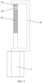
- the screw rod 5 includes: a first part 51, a second part 52, and a limiting part 53 located between the first part 51 and the second part 52.
- the first part 51 and the second part 52 each are a rod-shaped structure with threads on its surface
- the limiting part 53 is a rod-shaped structure without threads on its surface.
- a diameter of the limiting part 53 is smaller than a diameter of the first part 51 and a diameter the second part 52, and the foregoing predetermined area is an area to which the limiting part 53 corresponds in the screw rod 5.
- the camera apparatus in the embodiment of this disclosure further includes: a frame 8 fixedly connected to the screw rod 5, where a limiting component 9 is arranged on the frame 8, and the limiting component 9 is clamped on the limiting part 53.
- the frame 8 is formed by connecting two horizontal plates and a vertical plate.
- the two horizontal plates are located at both ends of the vertical plate, one horizontal plate is connected to a first end of the screw rod, and the other horizontal plate is connected to a second end of the screw rod.
- the limiting component 9 includes a limiting block 91 and a limiting plate 92.
- the limiting block 91 is fixedly connected to the frame 8. Specifically, the limiting block 91 is fastened to the vertical plate, and a sliding groove 911 is provided on the limiting block 91 in the central axis direction of the screw rod 5. A first end of the limiting plate 92 is located in the sliding groove 911, and a second end of the limiting plate 92 is provided with a first through hole 921.
- the first through hole 921 has internal threads, through which the first through hole 921 is engaged with the screw rod 5, and the second end of the limiting plate 92 is clamped on the limiting part 53 through the first through hole. Specifically, the second end of the limiting plate 92 is sleeved on the limiting part 53 through the first through hole.
- the transmission component 4 includes:
- the first fixing plate 41 and the second fixing plate 42 are arranged in parallel and located on different planes, and the first fixing plate 41 and the second fixing plate 42 are connected through a connecting plate.
- the third through hole 421 has internal threads, through which the third through hole 421 is engaged with the screw rod 5.
- the first fixing plate 41 includes: a first fixing part and a second fixing part (only a part is shown in FIG. 5 ) that have a same structure, where the first fixing part and the second fixing part each include a semicircular through hole, the semicircular through hole is clamped on the rotating shaft, and the first fixing part and the second fixing part are connected to form the second through hole.
- the first fixing part and the second fixing part are connected through a bolt.
- the first fixing plate 41 is formed by buckling two parts and is secured by a bolt, which can restrict movement of the camera module 1, the rotating shaft 2 and the first gear 3 in a direction parallel to the central axis direction of the screw rod.
- the camera module in the embodiment of this disclosure may be arranged in an accommodating space of a housing of the terminal.
- the camera module When the camera module is in a non-shooting state, the camera module is located in the accommodating space, and the motor does not operate. After a shooting function is started, the motor drives the screw rod 5 to start rotating.
- the second fixing plate 42 of the transmission component 4 is driven by the screw rod 5 to move upward, that is, the camera module 1 starts to be ejected from the housing 10 of the terminal.
- the limiting plate 92 of the limiting component 9 is located at a position of the limiting part 53 of the screw rod, and because this position has no threads, the limiting plate 92 stays at this position and does not move up or down.
- the second fixing plate 42 of the transmission component 4 reaches the limiting part 53 of the screw rod 5.
- the camera module 1 is ejected.
- the second fixing plate 422 pushes the limiting plate 92 into an upper screw rod (a first part) during a process in which the second fixing plate 422 enters the limiting part 53.
- the first gear 3 and the second gear 6 are meshed with each other, and a camera module rotation function is started.
- the motor drives the screw rod 5 and the second gear 6 to rotate, and the second gear 6 drives the first gear 3 to rotate, thereby implementing rotation of the camera module 1.
- the second fixing plate 42 is located in the limiting part 53 of the screw rod 5 and does not drive the camera module to move up or down, and the limiting plate 92 is driven by the screw rod 5 to move upward.
- the motor rotates reversely to drive the limiting plate 92 to move downward, the limiting plate 92 enters the limiting part 53 of the screw rod, and the limiting plate 92 no longer moves up or down.
- the limiting plate 92 pushes the second fixing plate 42 into a lower screw rod (a second part), and movement of the second fixing plate 42 drives the camera module to move downward, which is a retraction process of the camera module 1.
- the camera module 1 is moved down to a set value to complete the retraction of the camera module 1.
- the rotation of the rotating shaft may alternatively be not implemented by using the first gear and the second gear.
- the first gear and the second gear are not disposed, and the rotation of the rotating shaft is controlled by using a separate motor.
- the control mechanism drives the screw rod to rotate, and when the screw rod rotates, the transmission component is driven to move in the central axis direction of the screw rod, so that the camera module can protrude from the terminal.
- the screw rod rotates to drive the transmission component to move in the central axis direction, and when the transmission component moves to the predetermined position, the first gear meshes with the second gear to drive the camera module to rotate, so that the camera module can automatically rotate after protruding from the terminal.
- An embodiment of this disclosure provides a terminal, where a housing of the terminal is provided with an accommodating space, the terminal further includes the camera apparatus as describe above, and the camera apparatus is arranged in the accommodating space. All implementations of the foregoing camera apparatus are applicable to the terminal and a same technical effect can be achieved.
- the terminal in the embodiment of this disclosure includes a terminal formed by components such as a radio frequency unit, a network module, an audio output unit, an input unit, a sensor, a display unit, a user input unit, an interface unit, a memory, a processor, and a power supply.
- a radio frequency unit such as a radio frequency unit, a network module, an audio output unit, an input unit, a sensor, a display unit, a user input unit, an interface unit, a memory, a processor, and a power supply.
- the terminal in the embodiment of this disclosure may be a mobile phone, a tablet computer, a personal digital assistant, an in-vehicle computer, a music player, a laptop computer, or a navigator.
Landscapes
- Engineering & Computer Science (AREA)
- Signal Processing (AREA)
- General Engineering & Computer Science (AREA)
- Multimedia (AREA)
- Mechanical Engineering (AREA)
- Physics & Mathematics (AREA)
- General Physics & Mathematics (AREA)
- Studio Devices (AREA)
Description
- This disclosure relates to the field of camera technologies, and in particular, to a camera apparatus and a mobile terminal.
- Artificial intelligence (AI) is about to become a forefront field of the next wave of technologies, and implementation of artificial intelligence technologies strongly relies on implementation of a higher level of human-computer interaction. Image and video interaction represented by cameras has occupied a main position. A camera solution of a mobile phone in the related art includes a front camera and a rear camera, and they are both placed above (occasionally placed below) a display area of a screen. In order to better implement image and video human-computer interaction, various mobile phone manufacturers continuously improve a quantity of camera pixels in one aspect, and continuously increase a quantity of cameras in another aspect, and even a three-camera or four-camera solution has emerged. With the development of full-screen mobile phones, sizes of upper and lower black borders have been further compressed, and the front camera has become a bottleneck in design of a whole machine while a size of the whole machine remains unchanged. In the related art, although there is a camera that can be ejected from a terminal and used under an operation of a user to rotate a shooting direction, manual rotation of the camera is required, which increases the operation of the user.
-
CN 103 533 222 A discloses a full-automatic telescopic rotatable camera. The full-automatic telescopic rotatable camera comprises a connecting assembly, a transmission mechanism and a power motor which are connected in sequence. The connecting assembly is connected to the camera. The power motor has a first running direction and a second running direction which are opposite. In the first running direction, the camera is driven by the power motor through the transmission mechanism to extend out of an accommodating space in which the camera is located, and the rotation angle of the camera is controlled. In the second running direction, the camera is driven by the power motor through the transmission mechanism to retract to the accommodating space. -
CN 206 918 572 U discloses a monitoring camera device that can be conveniently adjusted. The camera includes a supporting plate, the top of which is fixedly connected with a drive case. The top of the inner wall of drive case is connected with a first bearing. The inner wall of the first bearing is fixedly connected with one end of a rotational shaft. The outer surface of the rotational shaft is fixedly coupled with a first gear. With the arrangement of the drive case, the first bearing, the rotational shaft, the first gear, the second gear, the motor and a supporting seat, the second gear is driven to rotate by the motor. The second gear, which engages with the first gear, can then drive the rotational shaft to rotate. Thereafter, the supporting seat at the bottom end of the rotational shaft drives the camera to rotate. Thus, the angle of the camera can be adjusted. This solves the problem of the existing camera device, in which the angle of the camera device cannot be conveniently adjusted. - The objective of this disclosure is to provide a camera apparatus and a mobile terminal, so as to solve the problem in the related art that a telescopic camera cannot automatically rotate after being ejected from a terminal. The invention is set out in the appended set of claims.
- To solve the foregoing technical problem, embodiments of this disclosure are implemented as follows:
- According to a first aspect, an embodiment of this disclosure provides a camera apparatus, including:
- a camera module;
- a rotating shaft fixedly connected to the camera module, where a first gear is fixed at one end, away from the camera module, of the rotating shaft;
- a transmission component fixed on the rotating shaft and abutting against the camera module;
- a screw rod rotatably connected to the transmission component, where a second gear is fixed on the screw rod, and the screw rod is arranged in parallel with the rotating shaft; and
- a control mechanism connected to the screw rod, where the control mechanism drives the screw rod to rotate, the screw rod rotates to drive the transmission component to move in a central axis direction of the rotating shaft, and when the transmission component moves to a predetermined position, the first gear meshes with the second gear to drive the camera module to rotate.
- According to a second aspect, an embodiment of this disclosure provides a terminal, where a housing of the terminal is provided with an accommodating space, the terminal further includes the camera apparatus as describe above, and the camera apparatus is arranged in the accommodating space.
- The embodiments of this disclosure have the following beneficial effects:
- According to the camera apparatus in the embodiments of this disclosure, the control mechanism drives the screw rod to rotate, and when the screw rod rotates, the transmission component is driven to move in the central axis direction of the screw rod, so that the camera module can protrude from the terminal. In addition, the screw rod rotates to drive the transmission component to move in the central axis direction of the rotating shaft, and when the transmission component moves to the predetermined position, the first gear meshes with the second gear to drive the camera module to rotate, so that the camera module can automatically rotate after protruding from the terminal.
- To describe the technical solutions in the embodiments of this disclosure more clearly, the following briefly describes the accompanying drawings for describing the embodiments of this disclosure. Apparently, the accompanying drawings in the following description show merely some embodiments of this disclosure, and persons of ordinary skill in the art may derive other drawings from these accompanying drawings without creative efforts.
-
FIG. 1 is a first schematic structural diagram of a camera apparatus according to an embodiment of this disclosure; -
FIG. 2 is a second schematic structural diagram of a camera apparatus according to an embodiment of this disclosure; -
FIG. 3 is a schematic structural diagram of a screw rod in a camera apparatus according to an embodiment of this disclosure; -
FIG. 4 is a schematic structural diagram of a limiting component in a camera apparatus according to an embodiment of this disclosure; -
FIG. 5 is a schematic structural diagram of a transmission component in a camera apparatus according to an embodiment of this disclosure; and -
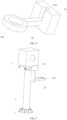
FIG. 6 is a schematic diagram of a camera apparatus ejected from a housing of a terminal according to an embodiment of this disclosure. - The following clearly and completely describes the technical solutions in the embodiments of this disclosure with reference to the accompanying drawings in the embodiments of this disclosure. Apparently, the described embodiments are merely some but not all of the embodiments of this disclosure. All other embodiments obtained by a person of ordinary skill in the art based on the embodiments of this disclosure without creative efforts shall fall within the protection scope of this disclosure.
- An embodiment of this disclosure provides a camera apparatus, applied to a terminal. The terminal may be specifically a smartphone, a tablet computer (PAD), a personal computer, or the like. As shown in
FIG. 1 andFIG. 2 , the camera apparatus includes: - a
camera module 1; - a rotating
shaft 2 fixedly connected to thecamera module 1, where afirst gear 3 is fixed at one end, away from thecamera module 1, of the rotatingshaft 2; - a
transmission component 4 fixed on the rotatingshaft 2 and abutting against thecamera module 1; - a
screw rod 5 rotatably connected to thetransmission component 4, where asecond gear 6 is fixed on thescrew rod 5, and thescrew rod 5 is arranged in parallel with the rotatingshaft 2; and - a
control mechanism 7 connected to thescrew rod 5, where thecontrol mechanism 7 drives thescrew rod 5 to rotate, thecontrol mechanism 7 includes a motor and a decelerator, thescrew rod 5 rotates to drive thetransmission component 4 to move in a central axis direction of the rotatingshaft 2, and when thetransmission component 4 moves to a predetermined position, thefirst gear 3 meshes with thesecond gear 6 to drive thecamera module 1 to rotate. - Specifically, the
first gear 3 is located below thesecond gear 6, and a distance between therotating shaft 2 and thescrew rod 5 is smaller than a sum of radii of thefirst gear 3 and thesecond gear 6, so that thefirst gear 3 and thesecond gear 6 are on a same plane, and they can be meshed with each other, to drive the first gear by the second gear to rotate and further to drive thecamera module 1 to rotate. - In a specific embodiment of this disclosure, the
control mechanism 7 controls thetransmission component 4 through thescrew rod 5 to move in a first direction, and when thetransmission component 4 moves in the first direction, thecamera module 1 and therotating shaft 2 are driven to move in the first direction. When one end of thetransmission component 4 moves to a predetermined area of thescrew rod 5, thefirst gear 3 meshes with thesecond gear 6 to drive the rotatingshaft 2 to rotate. When the rotatingshaft 2 rotates, thecamera module 1 is driven to rotate. The first direction is parallel to the central axis direction of thescrew rod 5. For example, moving in the first direction may be specifically moving upward in the central axis direction of the screw rod. - The
control mechanism 7 may also control thetransmission component 4 through thescrew rod 5 to move in a second direction opposite to the first direction. When thetransmission component 4 moves in the second direction, thecamera module 1 and therotating shaft 2 are driven to move in the second direction, thefirst gear 3 is separated from thesecond gear 6, therotating shaft 2 stops rotating. When therotating shaft 2 stops rotating, thecamera module 1 stops rotating. - In addition, a maximum rotation angle of the foregoing camera module is 360 degrees, that is, the
first gear 3 rotates once. - According to the camera apparatus in the embodiment of this disclosure, the control mechanism drives the screw rod to rotate, and when the screw rod rotates, the transmission component is driven to move in the central axis direction of the screw rod, so that the camera module can protrude from the terminal. In addition, the screw rod rotates to drive the transmission component to move in the central axis direction of the rotating shaft, and when the transmission component moves to the predetermined position, the first gear meshes with the second gear to drive the camera module to rotate, so that the camera module can automatically rotate after protruding from the terminal.
- In addition, in the camera apparatus in the embodiment of this disclosure, the camera module is telescopic and compatible with design of a full-screen mobile phone. Through rotation, the camera module can implement functions of front and rear cameras, saving a quantity of devices, further reducing device costs, and also saving stacking space of a whole machine. In addition, a panoramic shooting function can be implemented through control of an angular velocity of the rotating shaft.
- Further, as shown in
FIG. 3 , thescrew rod 5 includes:
afirst part 51, asecond part 52, and a limitingpart 53 located between thefirst part 51 and thesecond part 52. - The
first part 51 and thesecond part 52 each are a rod-shaped structure with threads on its surface, and the limitingpart 53 is a rod-shaped structure without threads on its surface. In addition, a diameter of the limitingpart 53 is smaller than a diameter of thefirst part 51 and a diameter thesecond part 52, and the foregoing predetermined area is an area to which the limitingpart 53 corresponds in thescrew rod 5. - Because an outer surface of the limiting
part 53 does not have threads, when one end of thetransmission component 4 moves to the limitingpart 53, this end of the transmission component stays at this position and does not move up or down. That thetransmission component 4 moves to the predetermined position means that one end of the transmission component moves to the limiting part. - Based on this, the camera apparatus in the embodiment of this disclosure further includes:
aframe 8 fixedly connected to thescrew rod 5, where a limitingcomponent 9 is arranged on theframe 8, and the limitingcomponent 9 is clamped on the limitingpart 53. - As shown in
FIG 1 andFIG. 2 , theframe 8 is formed by connecting two horizontal plates and a vertical plate. The two horizontal plates are located at both ends of the vertical plate, one horizontal plate is connected to a first end of the screw rod, and the other horizontal plate is connected to a second end of the screw rod. - As shown in
FIG. 4 , the limitingcomponent 9 includes a limitingblock 91 and a limitingplate 92. - The limiting
block 91 is fixedly connected to theframe 8. Specifically, the limitingblock 91 is fastened to the vertical plate, and a slidinggroove 911 is provided on the limitingblock 91 in the central axis direction of thescrew rod 5. A first end of the limitingplate 92 is located in the slidinggroove 911, and a second end of the limitingplate 92 is provided with a first throughhole 921. The first throughhole 921 has internal threads, through which the first throughhole 921 is engaged with thescrew rod 5, and the second end of the limitingplate 92 is clamped on the limitingpart 53 through the first through hole. Specifically, the second end of the limitingplate 92 is sleeved on the limitingpart 53 through the first through hole. - When one end of the
transmission component 4 moves to the limitingpart 53 of thescrew rod 5, the second end of the limitingplate 92 is pushed out of the limitingpart 53, and the limitingplate 92 is driven by thescrew rod 5 to move in the first direction. When thecontrol mechanism 7 controls thetransmission component 4 through thescrew rod 5 to move in the second direction opposite to the first direction, the limitingplate 92 is driven to move in the second direction. When the limitingplate 92 is moved to the limitingpart 53, one end of thetransmission component 4 is pushed out of the limitingpart 53, and thetransmission component 4 is driven by thescrew rod 5 to move in the second direction, so that thecamera module 1 extending protruding from the terminal can be retracted into the terminal. - Further, as shown in
FIG. 5 , thetransmission component 4 includes: - a
first fixing plate 41 provided with a second through hole, where thefirst fixing plate 41 is sleeved on therotating shaft 2 through the second through hole; and - a
second fixing plate 42 connected to thefirst fixing plate 41 and provided with a third throughhole 421, where thesecond fixing plate 42 is sleeved on thescrew rod 5 through the third throughhole 421 and is rotatably connected to thescrew rod 5. - The
first fixing plate 41 and thesecond fixing plate 42 are arranged in parallel and located on different planes, and thefirst fixing plate 41 and thesecond fixing plate 42 are connected through a connecting plate. - The third through
hole 421 has internal threads, through which the third throughhole 421 is engaged with thescrew rod 5. - Specifically, the
first fixing plate 41 includes:
a first fixing part and a second fixing part (only a part is shown inFIG. 5 ) that have a same structure, where the first fixing part and the second fixing part each include a semicircular through hole, the semicircular through hole is clamped on the rotating shaft, and the first fixing part and the second fixing part are connected to form the second through hole. The first fixing part and the second fixing part are connected through a bolt. - The
first fixing plate 41 is formed by buckling two parts and is secured by a bolt, which can restrict movement of thecamera module 1, therotating shaft 2 and thefirst gear 3 in a direction parallel to the central axis direction of the screw rod. - The camera module in the embodiment of this disclosure may be arranged in an accommodating space of a housing of the terminal. When the camera module is in a non-shooting state, the camera module is located in the accommodating space, and the motor does not operate. After a shooting function is started, the motor drives the
screw rod 5 to start rotating. In this state, thesecond fixing plate 42 of thetransmission component 4 is driven by thescrew rod 5 to move upward, that is, thecamera module 1 starts to be ejected from thehousing 10 of the terminal. At this moment, the limitingplate 92 of the limitingcomponent 9 is located at a position of the limitingpart 53 of the screw rod, and because this position has no threads, the limitingplate 92 stays at this position and does not move up or down. Thesecond fixing plate 42 of thetransmission component 4 reaches the limitingpart 53 of thescrew rod 5. In this case, as shown inFIG. 6 , thecamera module 1 is ejected. The second fixing plate 422 pushes the limitingplate 92 into an upper screw rod (a first part) during a process in which the second fixing plate 422 enters the limitingpart 53. Thefirst gear 3 and thesecond gear 6 are meshed with each other, and a camera module rotation function is started. The motor drives thescrew rod 5 and thesecond gear 6 to rotate, and thesecond gear 6 drives thefirst gear 3 to rotate, thereby implementing rotation of thecamera module 1. During this process, thesecond fixing plate 42 is located in the limitingpart 53 of thescrew rod 5 and does not drive the camera module to move up or down, and the limitingplate 92 is driven by thescrew rod 5 to move upward. - When the camera rotation function is disabled, the motor rotates reversely to drive the limiting
plate 92 to move downward, the limitingplate 92 enters the limitingpart 53 of the screw rod, and the limitingplate 92 no longer moves up or down. The limitingplate 92 pushes thesecond fixing plate 42 into a lower screw rod (a second part), and movement of thesecond fixing plate 42 drives the camera module to move downward, which is a retraction process of thecamera module 1. Thecamera module 1 is moved down to a set value to complete the retraction of thecamera module 1. - It should be noted that the rotation of the rotating shaft may alternatively be not implemented by using the first gear and the second gear. To be specific, the first gear and the second gear are not disposed, and the rotation of the rotating shaft is controlled by using a separate motor.
- According to the camera apparatus in the embodiment of this disclosure, the control mechanism drives the screw rod to rotate, and when the screw rod rotates, the transmission component is driven to move in the central axis direction of the screw rod, so that the camera module can protrude from the terminal. In addition, the screw rod rotates to drive the transmission component to move in the central axis direction, and when the transmission component moves to the predetermined position, the first gear meshes with the second gear to drive the camera module to rotate, so that the camera module can automatically rotate after protruding from the terminal.
- An embodiment of this disclosure provides a terminal, where a housing of the terminal is provided with an accommodating space, the terminal further includes the camera apparatus as describe above, and the camera apparatus is arranged in the accommodating space. All implementations of the foregoing camera apparatus are applicable to the terminal and a same technical effect can be achieved.
- The terminal in the embodiment of this disclosure includes a terminal formed by components such as a radio frequency unit, a network module, an audio output unit, an input unit, a sensor, a display unit, a user input unit, an interface unit, a memory, a processor, and a power supply.
- The terminal in the embodiment of this disclosure may be a mobile phone, a tablet computer, a personal digital assistant, an in-vehicle computer, a music player, a laptop computer, or a navigator.
- All embodiments in this specification are described in a progressive manner. Each embodiment focuses on what is different from other embodiments. For same or similar parts in the embodiments, mutual reference may be made.
- The invention is defined by the appended claims.
Claims (10)
- A camera apparatus, comprising:a camera module (1);a rotating shaft (2) fixedly connected to the camera module (1), wherein a first gear (3) is fixed at one end, away from the camera module (1), of the rotating shaft (2);a transmission component (4) fixed on the rotating shaft (2) and abutting against the camera module (1);a screw rod (5) rotatably connected to the transmission component (4), wherein a second gear (6) is fixed on the screw rod (5), and the screw rod (5) is arranged in parallel with the rotating shaft (2); anda control mechanism (7) connected to the screw rod (5), wherein the control mechanism (7) is configured to drive the screw rod (5) to rotate, the screw rod (5) is configured to rotate to drive the transmission component (4) to move in a central axis direction of the rotating shaft (2), and when the transmission component (4) moves to a predetermined position, the first gear (3) meshes with the second gear (6) to drive the camera module (1) to rotate.
- The camera apparatus according to claim 1, wherein the screw rod (5) comprises:a first part (51), a second part (52), and a limiting part (53) located between the first part (51) and the second part (52), whereinthe first part (51) and the second part (52) each are a rod-shaped structure with threads on its surface, and the limiting part (53) is a rod-shaped structure without threads on its surface.
- The camera apparatus according to claim 2, wherein a diameter of the limiting part (53) is smaller than a diameter of the first part (51) and a diameter the second part (52).
- The camera apparatus according to claim 2, further comprising:
a frame (8) fixedly connected to the screw rod (5), wherein a limiting component (9) is arranged on the frame (8), and the limiting component (9) is clamped on the limiting part (53). - The camera apparatus according to claim 4, wherein the limiting component (9) comprises a limiting block (91) and a limiting plate (92), wherein
the limiting block (91) is fixedly connected to the frame (8), and a sliding groove is provided on the limiting block (91) in the central axis direction of the screw rod (5), and a first end of the limiting plate (92) is located in the sliding groove, a second end of the limiting plate (92) is provided with a first through hole, and the second end of the limiting plate (92) is clamped on the limiting part (53) through the first through hole. - The camera apparatus according to claim 1, wherein the transmission component (4) comprises:a first fixing plate (41) provided with a second through hole, wherein the first fixing plate (41) is sleeved on the rotating shaft (2) through the second through hole; anda second fixing plate (42) connected to the first fixing plate (41) and provided with a third through hole, wherein the second fixing plate (42) is sleeved on the screw rod (5) through the third through hole; andthe first fixing plate (41) and the second fixing plate (42) are arranged in parallel and located on different planes.
- The camera apparatus according to claim 6, wherein the first fixing plate (41) comprises:
a first fixing part and a second fixing part that have a same structure, wherein the first fixing part and the second fixing part each comprise a semicircular through hole, and the first fixing part and the second fixing part are connected to form the second through hole. - The camera apparatus according to claim 7, wherein the first fixing part and the second fixing part are connected through a bolt.
- The camera apparatus according to claim 1, wherein the control mechanism (7) comprises a motor and a decelerator.
- A terminal, wherein a housing of the terminal is provided with an accommodating space, the terminal further comprises the camera apparatus according to any one of claims 1 to 9, and the camera apparatus is arranged in the accommodating space.
Applications Claiming Priority (2)
| Application Number | Priority Date | Filing Date | Title |
|---|---|---|---|
| CN201810776014.0A CN108600596B (en) | 2018-07-16 | 2018-07-16 | camera device and mobile terminal |
| PCT/CN2019/095363 WO2020015559A1 (en) | 2018-07-16 | 2019-07-10 | Camera apparatus and mobile terminal |
Publications (3)
| Publication Number | Publication Date |
|---|---|
| EP3826284A1 EP3826284A1 (en) | 2021-05-26 |
| EP3826284A4 EP3826284A4 (en) | 2021-08-04 |
| EP3826284B1 true EP3826284B1 (en) | 2024-08-07 |
Family
ID=63617570
Family Applications (1)
| Application Number | Title | Priority Date | Filing Date |
|---|---|---|---|
| EP19837236.9A Active EP3826284B1 (en) | 2018-07-16 | 2019-07-10 | Camera apparatus and mobile terminal |
Country Status (5)
| Country | Link |
|---|---|
| US (1) | US11683590B2 (en) |
| EP (1) | EP3826284B1 (en) |
| CN (1) | CN108600596B (en) |
| ES (1) | ES2992947T3 (en) |
| WO (1) | WO2020015559A1 (en) |
Families Citing this family (58)
| Publication number | Priority date | Publication date | Assignee | Title |
|---|---|---|---|---|
| CN108600596B (en) * | 2018-07-16 | 2020-01-31 | 维沃移动通信有限公司 | camera device and mobile terminal |
| CN109257467A (en) * | 2018-10-22 | 2019-01-22 | 深圳市兆威机电股份有限公司 | A kind of camera telescopic device and mobile phone |
| CN109088967B (en) * | 2018-10-24 | 2023-11-24 | Oppo(重庆)智能科技有限公司 | A camera assembly, electronic device and control method thereof |
| CN109040571B (en) * | 2018-10-31 | 2024-06-11 | 深圳市兆威机电股份有限公司 | Camera telescopic device and terminal |
| KR102471644B1 (en) * | 2018-11-09 | 2022-11-29 | 삼성전자주식회사 | Pop-up and rotation camera and electric device including the same |
| CN109714453B (en) * | 2018-11-29 | 2021-03-30 | Oppo(重庆)智能科技有限公司 | Electronic equipment with lifting camera and driving device and transmission mechanism thereof |
| CN209787206U (en) * | 2018-11-30 | 2019-12-13 | Oppo广东移动通信有限公司 | Transmission mechanism, drive mechanism assembly, installation drive assembly and mobile terminal |
| CN109831552B (en) * | 2018-12-28 | 2020-12-25 | 惠州Tcl移动通信有限公司 | Camera device and mobile terminal |
| CN111435951A (en) * | 2019-01-11 | 2020-07-21 | 北京小米移动软件有限公司 | Camera drive device and mobile terminal |
| CN109788683B (en) * | 2019-01-31 | 2020-09-29 | 维沃移动通信有限公司 | Electronic equipment |
| CN109873938B (en) * | 2019-02-18 | 2021-07-30 | 维沃移动通信(杭州)有限公司 | Terminal Equipment |
| CN109782854A (en) * | 2019-02-18 | 2019-05-21 | 维沃移动通信有限公司 | Terminal device |
| CN112219388B (en) * | 2019-02-21 | 2022-05-10 | 华为技术有限公司 | a wearable device |
| CN109873940A (en) * | 2019-02-26 | 2019-06-11 | 维沃移动通信有限公司 | Terminal device |
| CN109788179A (en) * | 2019-02-26 | 2019-05-21 | 维沃移动通信有限公司 | Terminal device |
| CN109889637B (en) * | 2019-03-29 | 2020-07-21 | 维沃移动通信有限公司 | Terminal Equipment |
| CN109995976A (en) * | 2019-03-31 | 2019-07-09 | 联想(北京)有限公司 | A kind of electronic equipment |
| CN110086904B (en) * | 2019-04-11 | 2020-09-01 | 维沃移动通信(杭州)有限公司 | Terminal Equipment |
| CN111835887B (en) * | 2019-04-16 | 2022-04-08 | 北京小米移动软件有限公司 | Camera structure and electronics |
| CN111835939B (en) * | 2019-04-16 | 2022-06-10 | 北京小米移动软件有限公司 | Camera structure and electronics |
| CN110086906A (en) * | 2019-04-16 | 2019-08-02 | 维沃移动通信(杭州)有限公司 | Terminal device |
| CN209982522U (en) * | 2019-04-22 | 2020-01-21 | Oppo广东移动通信有限公司 | Transmission mechanism, driving mechanism assembly, mounting driving assembly and mobile terminal |
| CN110099200B (en) * | 2019-04-23 | 2020-08-07 | 瑞声光电科技(常州)有限公司 | Imaging device, electronic apparatus, and method for using electronic apparatus |
| CN110213405B (en) * | 2019-04-24 | 2023-06-09 | 深圳市泰衡诺科技有限公司 | Mobile terminal and mobile terminal control method |
| CN111866229B (en) * | 2019-04-28 | 2022-05-03 | 北京小米移动软件有限公司 | an electronic device |
| CN111866227B (en) * | 2019-04-28 | 2021-12-03 | 北京小米移动软件有限公司 | Terminal device |
| CN110035213B (en) * | 2019-05-24 | 2024-04-05 | 深圳市兆威机电股份有限公司 | Camera mechanism and electronic equipment |
| WO2020252696A1 (en) * | 2019-06-19 | 2020-12-24 | 常州市瑞泰光电有限公司 | Camera system and mobile terminal |
| CN111147705B (en) * | 2019-07-02 | 2024-09-27 | 广东小天才科技有限公司 | Intelligent terminal device with multi-directional shooting module and tracking shooting method |
| CN110365826B (en) * | 2019-08-01 | 2021-03-23 | Oppo(重庆)智能科技有限公司 | Drive assembly, camera device and terminal equipment |
| CN112351161B (en) * | 2019-08-08 | 2022-03-04 | 荣耀终端有限公司 | A camera assembly and electronic equipment |
| CN110602275A (en) * | 2019-08-14 | 2019-12-20 | 华为技术有限公司 | Electronic equipment |
| CN112738362B (en) * | 2019-10-14 | 2023-08-08 | 瑞声科技(南京)有限公司 | Image pickup apparatus, electronic device, and method of using electronic device |
| CN112738298A (en) * | 2019-10-14 | 2021-04-30 | 瑞声科技(南京)有限公司 | Imaging device, electronic apparatus, and method for using electronic apparatus |
| CN110798597A (en) * | 2019-10-30 | 2020-02-14 | 深圳传音控股股份有限公司 | Shooting method and shooting device |
| CN112751996B (en) * | 2019-10-31 | 2024-10-18 | 北京小米移动软件有限公司 | Terminal device and shooting method |
| WO2021127917A1 (en) * | 2019-12-23 | 2021-07-01 | 诚瑞光学(常州)股份有限公司 | Photographing device, electronic apparatus, and method of using electronic apparatus |
| CN111147715B (en) * | 2019-12-23 | 2021-03-02 | 瑞声科技(南京)有限公司 | Image pickup device, method for controlling movement of image pickup device, and electronic apparatus |
| WO2021127902A1 (en) * | 2019-12-23 | 2021-07-01 | 诚瑞光学(常州)股份有限公司 | Lens lifting and rotating device and mobile terminal |
| CN111131672B (en) * | 2019-12-23 | 2022-03-08 | 诚瑞光学(常州)股份有限公司 | Imaging device, electronic apparatus, and method for using electronic apparatus |
| WO2021127938A1 (en) * | 2019-12-23 | 2021-07-01 | 诚瑞光学(常州)股份有限公司 | Image capture apparatus, electronic device, and method for using electronic device |
| WO2021127909A1 (en) * | 2019-12-23 | 2021-07-01 | 诚瑞光学(常州)股份有限公司 | Photographing apparatus, electronic device, and control method for electronic device |
| CN111147717B (en) * | 2019-12-24 | 2022-04-15 | 诚瑞光学(常州)股份有限公司 | Camera system and mobile terminal |
| CN111140738B (en) * | 2019-12-31 | 2021-11-16 | 维沃移动通信有限公司 | Driving mechanism and electronic device |
| CN111288263B (en) * | 2020-03-02 | 2021-04-27 | 诚瑞光学(常州)股份有限公司 | Elevating and rotating devices and electronic equipment |
| CN113542540B (en) * | 2020-04-21 | 2022-11-04 | 深圳市万普拉斯科技有限公司 | Camera Modules and Electronic Equipment |
| WO2021251679A1 (en) * | 2020-06-12 | 2021-12-16 | 삼성전자 주식회사 | Electronic device comprising flexible display and camera module |
| CN111667668A (en) * | 2020-06-12 | 2020-09-15 | 安徽新源农业科技有限公司 | A kind of tomato seedling disease monitoring and early warning device and method based on the Internet of Things |
| CN113938541B (en) * | 2020-06-29 | 2023-10-03 | Oppo广东移动通信有限公司 | Electronic equipment and camera components |
| CN114500778B (en) * | 2020-11-11 | 2023-10-24 | 北京小米移动软件有限公司 | Camera module and electronic equipment |
| CN112235499B (en) * | 2020-11-13 | 2025-04-18 | 北京小米移动软件有限公司 | Camera installation structure, camera module and terminal |
| CN112637450B (en) * | 2020-11-17 | 2022-05-13 | 深圳盛泰智能创新技术有限公司 | Camera of mobile terminal and use method thereof |
| CN114554033B (en) * | 2020-11-18 | 2025-07-25 | 北京小米移动软件有限公司 | Camera structure and terminal equipment |
| KR102460763B1 (en) * | 2020-12-04 | 2022-10-31 | 삼성전기주식회사 | camera module |
| CN113719710A (en) * | 2021-08-30 | 2021-11-30 | 彭少仕 | Overspeed monitoring equipment |
| CN114225597B (en) * | 2021-12-09 | 2023-02-28 | 苏州华之洁环境安全科技有限公司 | Dust device for environmental protection |
| CN117469537A (en) * | 2023-11-13 | 2024-01-30 | 江苏海事职业技术学院 | A kind of quick installation equipment for examination room monitoring |
| CN119713071B (en) * | 2025-02-28 | 2025-05-16 | 湖南巨达智慧数据科技有限公司 | Base, interaction terminal and human-job interaction recruitment information matching system |
Family Cites Families (17)
| Publication number | Priority date | Publication date | Assignee | Title |
|---|---|---|---|---|
| KR100678090B1 (en) * | 2004-04-02 | 2007-02-02 | 삼성전자주식회사 | Automatic draw-in / out device of camera lens module of mobile terminal |
| JP4522334B2 (en) * | 2005-07-07 | 2010-08-11 | 富士フイルム株式会社 | Imaging apparatus and portable electronic device |
| TWM283208U (en) * | 2005-08-10 | 2005-12-11 | Genius Electronic Optical Co Ltd | Zooming structure of lens |
| TWM324794U (en) * | 2007-03-12 | 2008-01-01 | Trident Medical Corp | Medical four-axial photography stand structure |
| TWI334057B (en) * | 2007-06-29 | 2010-12-01 | Coretronic Corp | Lens shifting device |
| CN103533222B (en) * | 2013-10-18 | 2016-08-24 | 路宽 | Full-automatic telescopic rotatable camera |
| TWI547665B (en) * | 2014-09-09 | 2016-09-01 | 鴻海精密工業股份有限公司 | Camera and rotating structure |
| CN105611148B (en) * | 2015-10-30 | 2018-12-04 | 上海创功通讯技术有限公司 | Mobile terminal and its camera module |
| CN105872339A (en) * | 2016-05-31 | 2016-08-17 | 广州宝镜智能科技有限公司 | Terminal with camera |
| CN106254581B (en) * | 2016-07-19 | 2019-04-12 | 北京小米移动软件有限公司 | Mobile terminal |
| CN106911883B (en) * | 2017-03-31 | 2020-11-27 | 努比亚技术有限公司 | Camera structure and mobile terminal |
| CN206918572U (en) * | 2017-04-26 | 2018-01-23 | 郑州小蝌蚪文化传播有限公司 | A kind of monitor camera device for being easy to regulation |
| CN207011146U (en) * | 2017-07-27 | 2018-02-13 | 北京小米移动软件有限公司 | Electronic equipment |
| CN107872609A (en) * | 2017-11-07 | 2018-04-03 | 广东欧珀移动通信有限公司 | Camera assembly structure and mobile terminal |
| CN108600596B (en) * | 2018-07-16 | 2020-01-31 | 维沃移动通信有限公司 | camera device and mobile terminal |
| US20220078313A1 (en) * | 2018-12-25 | 2022-03-10 | Huawei Technologies Co. , Ltd. | Camera assembly and terminal device |
| CN110095070B (en) * | 2019-05-13 | 2020-05-19 | 中国水利水电科学研究院 | IoT-based crop growth monitoring device and method |
-
2018
- 2018-07-16 CN CN201810776014.0A patent/CN108600596B/en active Active
-
2019
- 2019-07-10 EP EP19837236.9A patent/EP3826284B1/en active Active
- 2019-07-10 ES ES19837236T patent/ES2992947T3/en active Active
- 2019-07-10 WO PCT/CN2019/095363 patent/WO2020015559A1/en not_active Ceased
-
2021
- 2021-01-14 US US17/148,973 patent/US11683590B2/en active Active
Also Published As
| Publication number | Publication date |
|---|---|
| ES2992947T3 (en) | 2024-12-20 |
| CN108600596B (en) | 2020-01-31 |
| US20230069815A9 (en) | 2023-03-02 |
| WO2020015559A1 (en) | 2020-01-23 |
| CN108600596A (en) | 2018-09-28 |
| EP3826284A1 (en) | 2021-05-26 |
| US11683590B2 (en) | 2023-06-20 |
| EP3826284A4 (en) | 2021-08-04 |
| US20220368834A1 (en) | 2022-11-17 |
Similar Documents
| Publication | Publication Date | Title |
|---|---|---|
| US11683590B2 (en) | Image apparatus and mobile terminal | |
| CN111866227B (en) | Terminal device | |
| CN109788683A (en) | Electronic equipment | |
| CN111866229B (en) | an electronic device | |
| WO2021027123A1 (en) | Electronic device and control method therefor | |
| CN110177194A (en) | Camera system and mobile terminal | |
| CN108512953A (en) | Mobile phone camera lens telescoping device and mobile phone | |
| CN110602291B (en) | Electronic equipment | |
| CN109995915B (en) | Electronic product and camera sharing structure thereof | |
| WO2019128590A1 (en) | Electronic device and camera assembly thereof | |
| KR20210068272A (en) | Display Device with Changable Panel Size | |
| CN105840973A (en) | Hand-held cloud terraces and hand-held cloud terrace system | |
| CN110602277B (en) | Electronic device and control method thereof | |
| CN110602275A (en) | Electronic equipment | |
| CN110445898A (en) | Mobile terminal and its control method | |
| CN109788091B (en) | Electronic equipment | |
| WO2020135704A1 (en) | Terminal device | |
| CN116233288A (en) | Electronic equipment and its control method and control device | |
| WO2021127917A1 (en) | Photographing device, electronic apparatus, and method of using electronic apparatus | |
| WO2020199865A1 (en) | Terminal device | |
| CN207427310U (en) | Terminal device and its CCD camera assembly | |
| CN209897106U (en) | an electronic device | |
| CN210594486U (en) | Coiling mechanism, TV and computer | |
| CN108391100A (en) | A kind of rotary type monitoring device based on computer control | |
| CN211289274U (en) | Wireless display terminal of intelligent network system |
Legal Events
| Date | Code | Title | Description |
|---|---|---|---|
| STAA | Information on the status of an ep patent application or granted ep patent |
Free format text: STATUS: THE INTERNATIONAL PUBLICATION HAS BEEN MADE |
|
| PUAI | Public reference made under article 153(3) epc to a published international application that has entered the european phase |
Free format text: ORIGINAL CODE: 0009012 |
|
| STAA | Information on the status of an ep patent application or granted ep patent |
Free format text: STATUS: REQUEST FOR EXAMINATION WAS MADE |
|
| 17P | Request for examination filed |
Effective date: 20210210 |
|
| AK | Designated contracting states |
Kind code of ref document: A1 Designated state(s): AL AT BE BG CH CY CZ DE DK EE ES FI FR GB GR HR HU IE IS IT LI LT LU LV MC MK MT NL NO PL PT RO RS SE SI SK SM TR |
|
| A4 | Supplementary search report drawn up and despatched |
Effective date: 20210701 |
|
| RIC1 | Information provided on ipc code assigned before grant |
Ipc: H04N 5/225 20060101AFI20210625BHEP Ipc: H04M 1/02 20060101ALI20210625BHEP |
|
| DAV | Request for validation of the european patent (deleted) | ||
| DAX | Request for extension of the european patent (deleted) | ||
| REG | Reference to a national code |
Ref country code: DE Ref country code: DE Ref legal event code: R079 Ref document number: 602019056710 Country of ref document: DE Free format text: PREVIOUS MAIN CLASS: H04N0005225000 Ipc: F16M0011040000 |
|
| GRAP | Despatch of communication of intention to grant a patent |
Free format text: ORIGINAL CODE: EPIDOSNIGR1 |
|
| STAA | Information on the status of an ep patent application or granted ep patent |
Free format text: STATUS: GRANT OF PATENT IS INTENDED |
|
| RIC1 | Information provided on ipc code assigned before grant |
Ipc: H04M 1/02 20060101ALI20240207BHEP Ipc: H04N 23/57 20230101ALI20240207BHEP Ipc: H04N 23/50 20230101ALI20240207BHEP Ipc: G03B 17/04 20210101ALI20240207BHEP Ipc: F16M 11/18 20060101ALI20240207BHEP Ipc: F16M 11/08 20060101ALI20240207BHEP Ipc: F16M 11/04 20060101AFI20240207BHEP |
|
| INTG | Intention to grant announced |
Effective date: 20240301 |
|
| GRAS | Grant fee paid |
Free format text: ORIGINAL CODE: EPIDOSNIGR3 |
|
| GRAA | (expected) grant |
Free format text: ORIGINAL CODE: 0009210 |
|
| STAA | Information on the status of an ep patent application or granted ep patent |
Free format text: STATUS: THE PATENT HAS BEEN GRANTED |
|
| AK | Designated contracting states |
Kind code of ref document: B1 Designated state(s): AL AT BE BG CH CY CZ DE DK EE ES FI FR GB GR HR HU IE IS IT LI LT LU LV MC MK MT NL NO PL PT RO RS SE SI SK SM TR |
|
| REG | Reference to a national code |
Ref country code: GB Ref legal event code: FG4D |
|
| REG | Reference to a national code |
Ref country code: CH Ref legal event code: EP |
|
| REG | Reference to a national code |
Ref country code: IE Ref legal event code: FG4D |
|
| REG | Reference to a national code |
Ref country code: DE Ref legal event code: R096 Ref document number: 602019056710 Country of ref document: DE |
|
| REG | Reference to a national code |
Ref country code: NL Ref legal event code: FP |
|
| REG | Reference to a national code |
Ref country code: LT Ref legal event code: MG9D |
|
| REG | Reference to a national code |
Ref country code: ES Ref legal event code: FG2A Ref document number: 2992947 Country of ref document: ES Kind code of ref document: T3 Effective date: 20241220 |
|
| PG25 | Lapsed in a contracting state [announced via postgrant information from national office to epo] |
Ref country code: NO Free format text: LAPSE BECAUSE OF FAILURE TO SUBMIT A TRANSLATION OF THE DESCRIPTION OR TO PAY THE FEE WITHIN THE PRESCRIBED TIME-LIMIT Effective date: 20241107 |
|
| REG | Reference to a national code |
Ref country code: AT Ref legal event code: MK05 Ref document number: 1711295 Country of ref document: AT Kind code of ref document: T Effective date: 20240807 |
|
| PG25 | Lapsed in a contracting state [announced via postgrant information from national office to epo] |
Ref country code: FI Free format text: LAPSE BECAUSE OF FAILURE TO SUBMIT A TRANSLATION OF THE DESCRIPTION OR TO PAY THE FEE WITHIN THE PRESCRIBED TIME-LIMIT Effective date: 20240807 Ref country code: PL Free format text: LAPSE BECAUSE OF FAILURE TO SUBMIT A TRANSLATION OF THE DESCRIPTION OR TO PAY THE FEE WITHIN THE PRESCRIBED TIME-LIMIT Effective date: 20240807 Ref country code: GR Free format text: LAPSE BECAUSE OF FAILURE TO SUBMIT A TRANSLATION OF THE DESCRIPTION OR TO PAY THE FEE WITHIN THE PRESCRIBED TIME-LIMIT Effective date: 20241108 Ref country code: PT Free format text: LAPSE BECAUSE OF FAILURE TO SUBMIT A TRANSLATION OF THE DESCRIPTION OR TO PAY THE FEE WITHIN THE PRESCRIBED TIME-LIMIT Effective date: 20241209 |
|
| PG25 | Lapsed in a contracting state [announced via postgrant information from national office to epo] |
Ref country code: BG Free format text: LAPSE BECAUSE OF FAILURE TO SUBMIT A TRANSLATION OF THE DESCRIPTION OR TO PAY THE FEE WITHIN THE PRESCRIBED TIME-LIMIT Effective date: 20240807 |
|
| PG25 | Lapsed in a contracting state [announced via postgrant information from national office to epo] |
Ref country code: LV Free format text: LAPSE BECAUSE OF FAILURE TO SUBMIT A TRANSLATION OF THE DESCRIPTION OR TO PAY THE FEE WITHIN THE PRESCRIBED TIME-LIMIT Effective date: 20240807 |
|
| PG25 | Lapsed in a contracting state [announced via postgrant information from national office to epo] |
Ref country code: IS Free format text: LAPSE BECAUSE OF FAILURE TO SUBMIT A TRANSLATION OF THE DESCRIPTION OR TO PAY THE FEE WITHIN THE PRESCRIBED TIME-LIMIT Effective date: 20241207 Ref country code: AT Free format text: LAPSE BECAUSE OF FAILURE TO SUBMIT A TRANSLATION OF THE DESCRIPTION OR TO PAY THE FEE WITHIN THE PRESCRIBED TIME-LIMIT Effective date: 20240807 |
|
| PG25 | Lapsed in a contracting state [announced via postgrant information from national office to epo] |
Ref country code: HR Free format text: LAPSE BECAUSE OF FAILURE TO SUBMIT A TRANSLATION OF THE DESCRIPTION OR TO PAY THE FEE WITHIN THE PRESCRIBED TIME-LIMIT Effective date: 20240807 |
|
| PG25 | Lapsed in a contracting state [announced via postgrant information from national office to epo] |
Ref country code: RS Free format text: LAPSE BECAUSE OF FAILURE TO SUBMIT A TRANSLATION OF THE DESCRIPTION OR TO PAY THE FEE WITHIN THE PRESCRIBED TIME-LIMIT Effective date: 20241107 |
|
| PG25 | Lapsed in a contracting state [announced via postgrant information from national office to epo] |
Ref country code: RS Free format text: LAPSE BECAUSE OF FAILURE TO SUBMIT A TRANSLATION OF THE DESCRIPTION OR TO PAY THE FEE WITHIN THE PRESCRIBED TIME-LIMIT Effective date: 20241107 Ref country code: PT Free format text: LAPSE BECAUSE OF FAILURE TO SUBMIT A TRANSLATION OF THE DESCRIPTION OR TO PAY THE FEE WITHIN THE PRESCRIBED TIME-LIMIT Effective date: 20241209 Ref country code: PL Free format text: LAPSE BECAUSE OF FAILURE TO SUBMIT A TRANSLATION OF THE DESCRIPTION OR TO PAY THE FEE WITHIN THE PRESCRIBED TIME-LIMIT Effective date: 20240807 Ref country code: NO Free format text: LAPSE BECAUSE OF FAILURE TO SUBMIT A TRANSLATION OF THE DESCRIPTION OR TO PAY THE FEE WITHIN THE PRESCRIBED TIME-LIMIT Effective date: 20241107 Ref country code: LV Free format text: LAPSE BECAUSE OF FAILURE TO SUBMIT A TRANSLATION OF THE DESCRIPTION OR TO PAY THE FEE WITHIN THE PRESCRIBED TIME-LIMIT Effective date: 20240807 Ref country code: IS Free format text: LAPSE BECAUSE OF FAILURE TO SUBMIT A TRANSLATION OF THE DESCRIPTION OR TO PAY THE FEE WITHIN THE PRESCRIBED TIME-LIMIT Effective date: 20241207 Ref country code: HR Free format text: LAPSE BECAUSE OF FAILURE TO SUBMIT A TRANSLATION OF THE DESCRIPTION OR TO PAY THE FEE WITHIN THE PRESCRIBED TIME-LIMIT Effective date: 20240807 Ref country code: GR Free format text: LAPSE BECAUSE OF FAILURE TO SUBMIT A TRANSLATION OF THE DESCRIPTION OR TO PAY THE FEE WITHIN THE PRESCRIBED TIME-LIMIT Effective date: 20241108 Ref country code: FI Free format text: LAPSE BECAUSE OF FAILURE TO SUBMIT A TRANSLATION OF THE DESCRIPTION OR TO PAY THE FEE WITHIN THE PRESCRIBED TIME-LIMIT Effective date: 20240807 Ref country code: BG Free format text: LAPSE BECAUSE OF FAILURE TO SUBMIT A TRANSLATION OF THE DESCRIPTION OR TO PAY THE FEE WITHIN THE PRESCRIBED TIME-LIMIT Effective date: 20240807 Ref country code: AT Free format text: LAPSE BECAUSE OF FAILURE TO SUBMIT A TRANSLATION OF THE DESCRIPTION OR TO PAY THE FEE WITHIN THE PRESCRIBED TIME-LIMIT Effective date: 20240807 |
|
| PG25 | Lapsed in a contracting state [announced via postgrant information from national office to epo] |
Ref country code: DK Free format text: LAPSE BECAUSE OF FAILURE TO SUBMIT A TRANSLATION OF THE DESCRIPTION OR TO PAY THE FEE WITHIN THE PRESCRIBED TIME-LIMIT Effective date: 20240807 Ref country code: RO Free format text: LAPSE BECAUSE OF FAILURE TO SUBMIT A TRANSLATION OF THE DESCRIPTION OR TO PAY THE FEE WITHIN THE PRESCRIBED TIME-LIMIT Effective date: 20240807 Ref country code: SM Free format text: LAPSE BECAUSE OF FAILURE TO SUBMIT A TRANSLATION OF THE DESCRIPTION OR TO PAY THE FEE WITHIN THE PRESCRIBED TIME-LIMIT Effective date: 20240807 |
|
| PG25 | Lapsed in a contracting state [announced via postgrant information from national office to epo] |
Ref country code: EE Free format text: LAPSE BECAUSE OF FAILURE TO SUBMIT A TRANSLATION OF THE DESCRIPTION OR TO PAY THE FEE WITHIN THE PRESCRIBED TIME-LIMIT Effective date: 20240807 |
|
| PG25 | Lapsed in a contracting state [announced via postgrant information from national office to epo] |
Ref country code: CZ Free format text: LAPSE BECAUSE OF FAILURE TO SUBMIT A TRANSLATION OF THE DESCRIPTION OR TO PAY THE FEE WITHIN THE PRESCRIBED TIME-LIMIT Effective date: 20240807 |
|
| PG25 | Lapsed in a contracting state [announced via postgrant information from national office to epo] |
Ref country code: SK Free format text: LAPSE BECAUSE OF FAILURE TO SUBMIT A TRANSLATION OF THE DESCRIPTION OR TO PAY THE FEE WITHIN THE PRESCRIBED TIME-LIMIT Effective date: 20240807 |
|
| REG | Reference to a national code |
Ref country code: DE Ref legal event code: R097 Ref document number: 602019056710 Country of ref document: DE |
|
| PLBE | No opposition filed within time limit |
Free format text: ORIGINAL CODE: 0009261 |
|
| STAA | Information on the status of an ep patent application or granted ep patent |
Free format text: STATUS: NO OPPOSITION FILED WITHIN TIME LIMIT |
|
| PGFP | Annual fee paid to national office [announced via postgrant information from national office to epo] |
Ref country code: GB Payment date: 20250529 Year of fee payment: 7 |
|
| PGFP | Annual fee paid to national office [announced via postgrant information from national office to epo] |
Ref country code: NL Payment date: 20250613 Year of fee payment: 7 |
|
| 26N | No opposition filed |
Effective date: 20250508 |
|
| PGFP | Annual fee paid to national office [announced via postgrant information from national office to epo] |
Ref country code: FR Payment date: 20250610 Year of fee payment: 7 |
|
| PG25 | Lapsed in a contracting state [announced via postgrant information from national office to epo] |
Ref country code: SE Free format text: LAPSE BECAUSE OF FAILURE TO SUBMIT A TRANSLATION OF THE DESCRIPTION OR TO PAY THE FEE WITHIN THE PRESCRIBED TIME-LIMIT Effective date: 20240807 |
|
| PGFP | Annual fee paid to national office [announced via postgrant information from national office to epo] |
Ref country code: ES Payment date: 20250807 Year of fee payment: 7 |
|
| PGFP | Annual fee paid to national office [announced via postgrant information from national office to epo] |
Ref country code: DE Payment date: 20250528 Year of fee payment: 7 |
|
| REG | Reference to a national code |
Ref country code: CH Ref legal event code: H13 Free format text: ST27 STATUS EVENT CODE: U-0-0-H10-H13 (AS PROVIDED BY THE NATIONAL OFFICE) Effective date: 20260224 |
|
| PG25 | Lapsed in a contracting state [announced via postgrant information from national office to epo] |
Ref country code: LU Free format text: LAPSE BECAUSE OF NON-PAYMENT OF DUE FEES Effective date: 20250710 |
|
| REG | Reference to a national code |
Ref country code: BE Ref legal event code: MM Effective date: 20250731 |
|
| PG25 | Lapsed in a contracting state [announced via postgrant information from national office to epo] |
Ref country code: BE Free format text: LAPSE BECAUSE OF NON-PAYMENT OF DUE FEES Effective date: 20250731 |
|
| PG25 | Lapsed in a contracting state [announced via postgrant information from national office to epo] |
Ref country code: CH Free format text: LAPSE BECAUSE OF NON-PAYMENT OF DUE FEES Effective date: 20250731 |