EP3826044A1 - Mehrpoliger schalter - Google Patents
Mehrpoliger schalter Download PDFInfo
- Publication number
- EP3826044A1 EP3826044A1 EP20208382.0A EP20208382A EP3826044A1 EP 3826044 A1 EP3826044 A1 EP 3826044A1 EP 20208382 A EP20208382 A EP 20208382A EP 3826044 A1 EP3826044 A1 EP 3826044A1
- Authority
- EP
- European Patent Office
- Prior art keywords
- electrically conductive
- switch
- conductive material
- electrical
- actuation
- Prior art date
- Legal status (The legal status is an assumption and is not a legal conclusion. Google has not performed a legal analysis and makes no representation as to the accuracy of the status listed.)
- Granted
Links
- 239000004020 conductor Substances 0.000 claims abstract description 46
- 230000005405 multipole Effects 0.000 claims abstract description 22
- 230000002093 peripheral effect Effects 0.000 claims description 23
- 239000010408 film Substances 0.000 description 41
- 101150038956 cup-4 gene Proteins 0.000 description 35
- 229910052751 metal Inorganic materials 0.000 description 14
- 239000002184 metal Substances 0.000 description 14
- 230000000694 effects Effects 0.000 description 10
- 230000007704 transition Effects 0.000 description 5
- 238000010586 diagram Methods 0.000 description 4
- 239000000463 material Substances 0.000 description 4
- BQCADISMDOOEFD-UHFFFAOYSA-N Silver Chemical compound [Ag] BQCADISMDOOEFD-UHFFFAOYSA-N 0.000 description 3
- 230000006835 compression Effects 0.000 description 3
- 238000007906 compression Methods 0.000 description 3
- 230000036461 convulsion Effects 0.000 description 3
- 230000005489 elastic deformation Effects 0.000 description 3
- 238000004519 manufacturing process Methods 0.000 description 3
- 238000005381 potential energy Methods 0.000 description 3
- 229910052709 silver Inorganic materials 0.000 description 3
- 239000004332 silver Substances 0.000 description 3
- 239000004698 Polyethylene Substances 0.000 description 2
- 239000004743 Polypropylene Substances 0.000 description 2
- 238000009825 accumulation Methods 0.000 description 2
- 230000004913 activation Effects 0.000 description 2
- 238000005452 bending Methods 0.000 description 2
- 238000013461 design Methods 0.000 description 2
- 239000012636 effector Substances 0.000 description 2
- 210000000056 organ Anatomy 0.000 description 2
- 229920003229 poly(methyl methacrylate) Polymers 0.000 description 2
- -1 polyethylene Polymers 0.000 description 2
- 229920000573 polyethylene Polymers 0.000 description 2
- 239000004926 polymethyl methacrylate Substances 0.000 description 2
- 229920001155 polypropylene Polymers 0.000 description 2
- 230000002829 reductive effect Effects 0.000 description 2
- 229920001169 thermoplastic Polymers 0.000 description 2
- 239000004793 Polystyrene Substances 0.000 description 1
- 239000004676 acrylonitrile butadiene styrene Substances 0.000 description 1
- 238000004026 adhesive bonding Methods 0.000 description 1
- 238000001816 cooling Methods 0.000 description 1
- 229920001577 copolymer Polymers 0.000 description 1
- 235000021183 entrée Nutrition 0.000 description 1
- 230000009975 flexible effect Effects 0.000 description 1
- 238000010438 heat treatment Methods 0.000 description 1
- 229920001519 homopolymer Polymers 0.000 description 1
- 230000000670 limiting effect Effects 0.000 description 1
- 239000012528 membrane Substances 0.000 description 1
- 239000011104 metalized film Substances 0.000 description 1
- 238000001465 metallisation Methods 0.000 description 1
- 239000000203 mixture Substances 0.000 description 1
- 239000004417 polycarbonate Substances 0.000 description 1
- 229920000515 polycarbonate Polymers 0.000 description 1
- 239000004800 polyvinyl chloride Substances 0.000 description 1
- 230000009467 reduction Effects 0.000 description 1
- 238000007493 shaping process Methods 0.000 description 1
- 239000007787 solid Substances 0.000 description 1
- 238000003856 thermoforming Methods 0.000 description 1
- 210000003813 thumb Anatomy 0.000 description 1
Images


Classifications
-
- H—ELECTRICITY
- H01—ELECTRIC ELEMENTS
- H01H—ELECTRIC SWITCHES; RELAYS; SELECTORS; EMERGENCY PROTECTIVE DEVICES
- H01H13/00—Switches having rectilinearly-movable operating part or parts adapted for pushing or pulling in one direction only, e.g. push-button switch
- H01H13/02—Details
- H01H13/26—Snap-action arrangements depending upon deformation of elastic members
- H01H13/48—Snap-action arrangements depending upon deformation of elastic members using buckling of disc springs
-
- H—ELECTRICITY
- H01—ELECTRIC ELEMENTS
- H01H—ELECTRIC SWITCHES; RELAYS; SELECTORS; EMERGENCY PROTECTIVE DEVICES
- H01H13/00—Switches having rectilinearly-movable operating part or parts adapted for pushing or pulling in one direction only, e.g. push-button switch
- H01H13/02—Details
- H01H13/12—Movable parts; Contacts mounted thereon
- H01H13/14—Operating parts, e.g. push-button
-
- H—ELECTRICITY
- H01—ELECTRIC ELEMENTS
- H01H—ELECTRIC SWITCHES; RELAYS; SELECTORS; EMERGENCY PROTECTIVE DEVICES
- H01H13/00—Switches having rectilinearly-movable operating part or parts adapted for pushing or pulling in one direction only, e.g. push-button switch
- H01H13/50—Switches having rectilinearly-movable operating part or parts adapted for pushing or pulling in one direction only, e.g. push-button switch having a single operating member
- H01H13/52—Switches having rectilinearly-movable operating part or parts adapted for pushing or pulling in one direction only, e.g. push-button switch having a single operating member the contact returning to its original state immediately upon removal of operating force, e.g. bell-push switch
-
- H—ELECTRICITY
- H01—ELECTRIC ELEMENTS
- H01H—ELECTRIC SWITCHES; RELAYS; SELECTORS; EMERGENCY PROTECTIVE DEVICES
- H01H2203/00—Form of contacts
- H01H2203/036—Form of contacts to solve particular problems
- H01H2203/038—Form of contacts to solve particular problems to be bridged by a dome shaped contact
-
- H—ELECTRICITY
- H01—ELECTRIC ELEMENTS
- H01H—ELECTRIC SWITCHES; RELAYS; SELECTORS; EMERGENCY PROTECTIVE DEVICES
- H01H2203/00—Form of contacts
- H01H2203/036—Form of contacts to solve particular problems
- H01H2203/054—Form of contacts to solve particular problems for redundancy, e.g. several contact pairs in parallel
-
- H—ELECTRICITY
- H01—ELECTRIC ELEMENTS
- H01H—ELECTRIC SWITCHES; RELAYS; SELECTORS; EMERGENCY PROTECTIVE DEVICES
- H01H2205/00—Movable contacts
- H01H2205/016—Separate bridge contact
-
- H—ELECTRICITY
- H01—ELECTRIC ELEMENTS
- H01H—ELECTRIC SWITCHES; RELAYS; SELECTORS; EMERGENCY PROTECTIVE DEVICES
- H01H2209/00—Layers
- H01H2209/068—Properties of the membrane
- H01H2209/07—Properties of the membrane metallic
-
- H—ELECTRICITY
- H01—ELECTRIC ELEMENTS
- H01H—ELECTRIC SWITCHES; RELAYS; SELECTORS; EMERGENCY PROTECTIVE DEVICES
- H01H2215/00—Tactile feedback
- H01H2215/004—Collapsible dome or bubble
- H01H2215/022—Asymmetric; Elliptic; Square
- H01H2215/024—Spider
-
- H—ELECTRICITY
- H01—ELECTRIC ELEMENTS
- H01H—ELECTRIC SWITCHES; RELAYS; SELECTORS; EMERGENCY PROTECTIVE DEVICES
- H01H2225/00—Switch site location
- H01H2225/006—Switch site location more then one pole
-
- H—ELECTRICITY
- H01—ELECTRIC ELEMENTS
- H01H—ELECTRIC SWITCHES; RELAYS; SELECTORS; EMERGENCY PROTECTIVE DEVICES
- H01H2225/00—Switch site location
- H01H2225/008—Two different sites for one circuit, e.g. for safety
-
- H—ELECTRICITY
- H01—ELECTRIC ELEMENTS
- H01H—ELECTRIC SWITCHES; RELAYS; SELECTORS; EMERGENCY PROTECTIVE DEVICES
- H01H2225/00—Switch site location
- H01H2225/01—Different switch sites under one actuator in same plane
Definitions
- the present invention relates to a multi-pole switch for selectively opening or closing at least two electrical circuits.
- Switches for industrial machines are widely used in industry. They are connected to the machine control system, and allow an operator to interact with the control system, in particular to stop the operation of the machine in the case of an emergency stop switch for example.
- a particular type of switch comprises contact zones connected to an electrical circuit, and an actuation button mechanically connected to a part made of conductive material.
- the actuation button moves or deforms, and causes the part made of conductive material to come into contact with the electric circuit: the electric circuit thus passes from the open state to the closed state.
- An instruction corresponding to the function of the switch is sent to the control system which then controls the various effector organs of the machine as a function of the instruction received.
- Redundancy consists in doubling the information at the input of a system and / or the effector organs at the output.
- redundancy consists in doubling the number of electrical circuits to perform the same function. For example, two electrical circuits are used instead of one to ensure the emergency stop of a machine. Thus, if a failure is observed in the closing of one of the two electrical circuits, the instruction can still be carried out thanks to the closing of the other electrical circuit, which improves safety.
- a first switch 100 enables the first electrical circuit to be opened or closed
- a second switch 101 enables the second electrical circuit to be opened or closed.
- the two switches 100, 101 must be actuated simultaneously. So we generally provides a single actuation button 120 which is common to the two switches. The actuation of this single actuation button enables the two electrical circuits to be closed simultaneously.
- An object of the invention is to provide a multipolar switch making it possible to overcome the drawbacks described above.
- the invention aims in particular to provide a multipolar switch having a reduced size compared to known switches.
- the invention aims most particularly to provide a multipolar switch making it possible to improve the tactile effect, also called the haptic effect, felt by a user when he actuates the switch.
- the invention relates to a multi-pole switch for selectively opening or closing at least two electrical circuits.
- the two electrical circuits are electrically isolated from each other.
- the multipolar switch 1 is based on the principle of redundancy of the electrical signal, and for this purpose makes it possible to open or close the two electrical circuits simultaneously (not shown), by actuation of the actuation button 14 of said switch, as illustrated in figure 2 .
- a single switch 1 is sufficient to close the two electrical circuits, while two switches each opening or closing a respective electrical circuit were necessary in the state of the art. This leads to a reduction in the size of the actuation system within the industrial machine, and thus limits the constraints during the design and manufacture and use of the industrial machine.
- the multipolar switch 1 comprises a part made of electrically conductive material 4 advantageously in the form of a metal cup, allowing a user to actuate the switch.
- This type of metal cup is known per se in the field of electronic devices.
- the switch shown in figures 3A , 3B , 4 , and 5 is a one-LED switch.
- the switch according to the first embodiment is however not limited to an LED switch and the operation of such an LED will not be described in this text.
- the cup 4 is advantageously preformed. It is in the form of a disc, comprising a central part 7, an intermediate part 8 which extends around the central part, and a peripheral part 9 which extends around the intermediate part.
- the invention is not however limited to a cup in the form of a disc, and other shapes are suitable depending on the type of switch, for example a square, rectangular or even triangular shape.
- the cup 4 is curved at the level of the central part 7. It has an upper face 23, and a lower face 24 opposite the upper face with respect to said cup.
- the cup 4 is configured to deform elastically when it is mechanically requested by a user in a direction of actuation of the switch.
- the direction of actuation is represented by the arrow X on the figure 4 .
- the mechanical force is applied from the upper face 23 of the cup, which can be directly accessible by the user, or alternatively be provided with an actuation button (not shown) on which the user can press to mechanically apply the cup.
- the cup 4 then deforms at its intermediate part 8, passing from a convex curvature in which the central part 7 is directed away from the peripheral part 9 in the X direction, to a concave curvature in which the part central 7 is directed towards said peripheral part 9.
- the curvature of the cup is reversed: the latter changes from a convex curvature to a concave curvature by deformation of its intermediate part.
- the central part 7 for its part does not deform, or at least, only deforms very slightly.
- the transition of the cup 4 from the convex curvature to the concave curvature, during its deformation, is felt by the user as a very slight jerk reflecting the maximum compression of the intermediate part.
- the user thus feels a tactile or haptic effect, that is to say a force feedback, when he presses on the cup to actuate the switch. He then knows, without it being necessary to check it visually, that the cup is deformed and that the switch is actuated.
- the cup 4 advantageously has recessed portions 25, which make it possible to improve its deformation, that is to say that a reduced pressure is necessary on the part of the user to obtain a deformation of the recessed cup similar to that of a full cup.
- Switch 1 further comprises electrical contact zones.
- the electrical contact zones are located under the cup, facing the lower face 24 of said cup.
- four electrical contact zones 2a, 2b, 3ab, 3b are present.
- the first electrical contact areas 2a, 2b are electrically connected to a first electrical circuit, that is to say they make up the first electrical circuit, and the second electrical contact areas 3a, 3b are electrically connected to a second electric circuit (not shown), that is to say they make up the second electric circuit.
- the first and second electrical circuits are electrically isolated from each other.
- Switch 1 also comprises a film 32 which at least partially covers the underside of the metal cup. Film 32 is particularly visible on the figure 5 illustrating a sectional view of the switch.
- the film 32 comprises a first and a second electrically conductive portions 26, 27 electrically insulated from one another by a first and a second electrically insulating portions 28, 29.
- the first and second electrically conductive portions 26, 27 preferably comprise an electrically conductive material which covers the film 32.
- the first and second electrically conductive portions 26, 27 preferably comprise metal tracks screen-printed on the film 32, preferably silver tracks.
- Each electrically conductive portion 26, 27 is arranged so as to come into contact with one or more respective electrical contact zones 2a, 2b and 3a, 3b, when the switch is actuated, in order to close the corresponding electrical circuit.
- the first electrically conductive portion 26 is arranged at the level of the intermediate part 8 of the cup, so as to come into contact with the two first electrical contact zones 2a, 2b
- the second electrically electric portion 27 is arranged at the level of the intermediate part 8 of the cup, opposite the first electrically conductive portion 26 with respect to the center of the cup 4, so as to come into contact with the two second electrical contact zones 3a, 3b.
- the first and second electrically conductive portions 26, 27 are electrically insulated from one another by the two electrically insulating portions 28, 29 located between them.
- the operation of the switch according to the first embodiment is as follows.
- Switch 1 is initially at rest.
- the cup 4 is in a rest configuration in which its central part 7 and its intermediate part 8 have a convex curvature.
- the cup 4, in particular the insulating film 32 covering its lower face, is distant from the electrical contact zones 2a, 2b, 3a, 3b.
- the intermediate part 8 of the cup then takes on a concave curvature.
- the first electrically conductive portion 26 comes into contact with the two first electrical contact areas 2a, 2b, thus closing the first electrical circuit
- the second electrically conductive portion 27 comes into contact with the two second electrical contact areas 3a, 3b, thus closing the second electrical circuit.
- the cup 4 is then in an actuation configuration, and the switch is actuated.
- the force feedback induced by the transition of the cup 4 between its rest configuration and its actuated position informs the user in a tactile manner of the actuation of the switch.
- the multipolar switch 1 comprises two metal cups, including a first cup 4 and a second cup 5.
- the metal cups 4, 5 are similar to those described in the first embodiment, except that the latter are preferably solid. Indeed, it is not necessary to make cutouts in the cups to allow the operation of the switch according to this second embodiment.
- the first and the second cup 4, 5 are arranged one above the other, facing each other, the first cup 4 being located above the second cup 5.
- the two cups 4, 5 are housed in a housing 13 provided with a bottom 19 delimited laterally by a lateral surface 20 which extends from the bottom 19 away from the bottom.
- the peripheral part 8 of the two cups 4, 5 is fixed to the housing.
- the two cups 4, 5 are arranged so that their convex curvature deviates from the median plane which extends between the two cups.
- the upper face of the first cup is therefore directed upwards in the plane of the sheet, opposite the housing, while the upper face of the second cup is directed downwards in the plane of the sheet, towards the bottom 19 of the housing.
- the multipolar switch 1 further comprises a film 33 arranged between the two cups 4, 5.
- the film 33 comprises first electrically conductive zones or portions 2a, 2b, 2c deposited on the upper face of the film facing the first cup 4, and second electrically conductive portions 3a, 3b, 3c deposited on the lower face of the film forming facing the second cup 5.
- the first and second electrically conductive portions 2a, 2b, 2c, 3a, 3b, 3c preferably comprise metal tracks screen-printed on the film, preferably silver tracks.
- the first and second electrically conductive portions 2a, 2b, 2c, 3a, 3b, 3c are arranged on either side of the film 33, facing each other, at the peripheral part 9 of the two cups 4, 5, and are then called peripheral electrically conductive portions 2a, 2c, 3a, 3c, and at the level of the central part 7 of the two cups, and are then called central electrically conductive portions 2b, 3b.
- the first electrically conductive portions 2a, 2b, 2c are electrically connected to a first electrical circuit (not shown), that is to say they make up the first electrical circuit, and the second electrically conductive portions 3a, 3b, 3c are electrically connected to a second electric circuit (not shown), that is to say they make up the second electric circuit.
- the first electrically conductive portions 2a, 2b, 2c are respectively electrically isolated from the second electrically conductive portions 3a, 3b, 3c by electrically insulating portions 54 of the film which separate them, at the level of the central part 7 and of the peripheral part 9 of the cups.
- the central electrically conductive portions 2b, 3b are electrically insulated from the peripheral electrically conductive portions 2a, 2c, 3a, 3c by electrically insulating portions 55 of the film.
- the upper face 23 of the second cup 5 is in contact with the bottom 13 of the housing, at the level of its central part 7.
- a lug 30 projecting from the bottom 19 of the housing is advantageously provided in order to serve as a stop for the central part 7. of the second cup.
- the multi-pole switch 1 further comprises an actuation button 14.
- the actuating button 14 is mounted on the housing 13. It comprises an upper surface 31, and a lower surface 22 bearing against the upper surface of the first cup, at its central part.
- the actuation button 14 is movable by actuation between a rest position in which the first and second electrical circuits are open, and an actuation position by application of pressure by a user on its upper face 31, in which the cups 4, 5 are mechanically stressed to deform them elastically relative to the housing 13, in order to close the first and the second electrical circuit.
- the actuation button 14 is preferably a push button configured to return to its rest position from its actuation position when the user releases said push button.
- Switch 1 is initially at rest, as shown in figure 6 .
- the two cups 4, 5 are in a rest configuration in which their central part 7 and their intermediate part 8 have a convex curvature.
- the central part 7 of each of the two cups 4, 5 is remote from the central electrically conductive portions 2b, 3b.
- the first cup 4 deforms elastically according to the force exerted by the user.
- the central part 7 and the intermediate part 8 of the first cup 4 then take on a concave curvature, and said central part of the first cup comes into contact with the first central electrically conductive portion 2b, thus closing the first electrical circuit.
- the intermediate part is deformed, while the central part 7 does not deform, or at least, only deforms very slightly.
- the second cup 5 is deformed simultaneously with, and in a manner similar to, the first cup.
- the central part 7 of the second cup 5 comes into contact with the second central electrically conductive portion 3b, thus closing the second electrical circuit.
- the multipolar switch 1 comprises an electrically insulating thermoformed film 34.
- thermoformed film 34 can be manufactured by heating the material in order to soften it, then by shaping the material thus become ductile so that it takes a predetermined shape, and retains it after cooling to room temperature.
- thermoformed film 34 can be formed cold, that is to say at room temperature.
- the material of the thermoformed film preferably comprises a thermoplastic polymer suitable for being shaped by thermoforming.
- thermoplastic polymer is preferably chosen from: polystyrene (PS), polyethylene (PE), polypropylene (PP), polycarbonate (PC), acrylonitrile butadiene styrene (ABS), polyvinyl chloride (PVC), polymethyl methacrylate (PMMA), and mixtures thereof, present in the form of homopolymers or of copolymers.
- PS polystyrene
- PE polyethylene
- PP polypropylene
- PC polycarbonate
- ABS acrylonitrile butadiene styrene
- PVC polyvinyl chloride
- PMMA polymethyl methacrylate
- thermoformed film 34 comprises an upper face 35 and a lower face 36 opposite to the upper face with respect to the film.
- thermoformed film 34 includes a domed portion 37, i.e. a convex prominence which extends from a substantially planar portion of the film.
- the domed portion 37 comprises a bearing surface 38 on the upper face 35 of the film, on which the user can press, by exerting a force oriented from the upper face towards the underside of the film, in order to elastically deform the film.
- the upper face 35 of the thermoformed film is advantageously covered, at least at the level of the convex portion 37, with a metallic layer 39 making it possible to reinforce the tactile effect when the switch is actuated by deformation of the convex portion of the. thermoformed film.
- the metallic layer 39 is preferably deposited by metallization of the upper surface of the thermoformed film, or by gluing.
- Switch 1 further comprises at least two electrically conductive zones 40a, 40b arranged on the underside of the thermoformed film, electrically separated from one another by an electrically insulating portion 41.
- the electrically conductive zones are configured to come to the fore. contact of a first and a second respective electrical contact zone (not shown).
- the electrically conductive zones 40a, 40b are metal tracks screen-printed on the thermoformed film, preferably silver tracks.
- the insulating portion 41 preferably consists of a portion of the thermoformed film.
- thermoformed film 34 is in a rest configuration in which the domed portion 37 has a convex curvature.
- the electrically conductive areas 40a, 40b are remote from the electrical contact areas.
- the domed portion 37 then takes on a concave curvature, and the first and second electrically conductive zones 40a, 40b respectively come into contact with the first and second electric contact zones, thus closing the first and the second electric circuit.
- the thermoformed film 34 is then in an actuation configuration, and the switch 1 is actuated.
- the force feedback induced by the transition of the curved portion 37 of the thermoformed film 34 between its rest configuration and its actuated configuration informs the user in a tactile manner of the actuation of the switch.
- the multipolar switch 1 comprises two elastically deformable parts 4, 5 made of an electrically conductive material.
- the switch 1 comprises a housing 13 provided with an upper surface 16, a lower surface 17, and a blind hole 18 which extends in the housing from the upper surface towards the lower face.
- the orifice 18 is provided with a bottom 19 and a side surface 20 which extends from the bottom towards the upper surface of the housing.
- Switch 1 further comprises at least a first electrical contact zone connected to a first electrical circuit, that is to say that it makes up the first electrical circuit, and at least a second electrical contact zone connected to a first electrical circuit.
- second electrical circuit that is to say, it makes up the second electrical circuit.
- the first and the second electrical contact zone are in the form of electrical contact pads 2a, 2b, 2c, and 3a, 3b, 3c arranged on the bottom 19 of the housing.
- the pads 2a, 2b, and 2c are connected to the first electrical circuit, and the pads 3a, 3b, and 3c are connected to the second electrical circuit.
- the first electrical circuit is electrically isolated from the second electrical circuit.
- the multipolar switch 1 comprises a first part made of electrically conductive material 4 and a second part of electrically conductive material 5, both of which are in the form of a metal cup.
- the metal cups are similar in their manufacture to those described in the first and in the second embodiment, but differ from them in their shape.
- the first and the second cup 4, 5 have the shape of a star with several branches 10, or legs.
- the metal cups include three legs.
- the first and the second cup 4, 5 comprise a central part 7 from which extend the three tabs 10 which constitute the intermediate part 8 of the cup.
- the ends 12 of the legs constitute the peripheral part of the cup.
- the first and the second cup 4, 5 are curved at their central part 7.
- the tabs 10 extend from the central part 7 towards their ends 12 while bending, so as to move away. longitudinally and transversely of said central part.
- the legs 10 extend from the central part 7 by widening, that is to say by widening in a regular manner in the direction of their end 12.
- the legs 10 are separated from each other by notches 11.
- the notches have a curved shape which corresponds to the flaring of the legs 10.
- the first and the second cup 4, 5 are able to deform elastically, by accumulation and release of potential energy, at their intermediate part 8, that is to say the tabs 10, passing from a convex curvature. to a concave curvature.
- the central part 7 for its part does not deform, or at least, only deforms very slightly.
- the first cup 4 is arranged on and at a distance from the electrical contact pads 2a, 2b, 2c, 3a, 3b, 3c.
- An electrically insulating layer 6 is arranged between the first 4 and the second cup 5 in order to electrically insulate them from one another.
- the first cup 4 is arranged so that its ends 12 face the first electrical contact zone according to the direction of actuation. More precisely, each end 12 of the first cup faces a corresponding first electrical contact pad 2a, 2b, 2c.
- the second cup 5 is arranged on the first metal cup 4, and is offset with respect to the latter by an angle determined along an axis perpendicular to the longitudinal plane containing the central part of the second cup. Due to this offset, each of the ends 12 of the second cup 5 coincides with a corresponding notch 11 of the first cup 4, and each end 12 of the second cup 5 faces a second electrical contact pad 3a, 3b, 3c corresponding. In the embodiment shown in figure 9 , the second cup 5 is offset by an angle of 60 ° relative to the first cup 4.
- the first and the second cup 4, 5 are initially in a rest configuration, in which said parts are distant from the first and second electrical contact zones 2a, 2b, 2c, 3a, 3b, 3c.
- the first and second electrical circuits are therefore open.
- the actuation button changes from a position of rest position to an actuation position in which it transmits the pressure of the user to the central part 7 of the second cup 5.
- the second cup 5 elastically deforms and presses against the first part 4, via the electrically insulating layer 6, thus causing the deformation of said first cup 4 .
- the first and second parts 4, 5 are then in an activated configuration.
- the first cup 4 is in contact with the first electrical contact pads 2a, 2b, 2c, and the second cup 5 is in contact with the second electrical contact pads 3a, 3b, 3c, thus making it possible to close the first and second electrical circuits respectively.
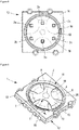
- the figure 10 illustrates a fifth embodiment of the multipolar switch according to the invention.
- the fifth embodiment differs from the fourth embodiment described above by the structure of the first and second parts of electrically conductive material 4, 5.
- the first part 4 comprises four legs 10, and these extend from the central part 7 of the part, tapering regularly towards their end.
- the first part 4 is convex at the level of its central part 7, as illustrated by figure 13 .
- the tabs 10 extend from the central part 7 towards their ends 12 by bending, so as to move away longitudinally and transversely from said central part.
- the second part 5 is in the shape of an X, as shown in the figures 10 and 15 . It comprises a central part comprising a disc 42 pierced with an opening 21 in its center, as well as an intermediate part comprising four tabs 10 which extend from the central part, to their ends 12 which constitute the peripheral part of the room.
- the tabs 10 are preferably curved in order to promote the elastic deformation of the first part.
- the first part 4 is arranged so that two opposite ends 12 among its four ends each face a first electrical contact pad 2a, 3b.
- the electrical contact 2a is connected to a first electrical circuit via a terminal 48 located on the housing and projecting outside the latter.
- the electrical contact 3b is connected to the first electrical circuit via a terminal 49 located on the housing and projecting outside the latter.
- the first part 4 is able to deform elastically, by accumulation and release of potential energy, at its intermediate part 8, that is to say of its legs 10, passing from a convex curvature to a concave curvature. .
- Its central part 7 for its part does not deform, or at the very least, only deforms very slightly.
- the transition of the first part 4 from a convex curvature to a concave curvature, during its deformation, is felt by the user as a very slight jerk reflecting the maximum compression of the intermediate part.
- the user thus feels a haptic or force feedback effect when he presses on the second part 5 to actuate the switch. He then knows, without it being necessary to check it visually, that the first part 4 is deformed and that the switch is actuated.
- the second part 5 is arranged on the first part 4 so that each of the ends 12 of the second part 5 coincides with a corresponding space between two consecutive tabs 10 of the first part 4.
- Each end 12 of the second part 5 faces to a corresponding second electrical contact pad 2b, 2c, 3a, 3c.
- the electrical contacts 2b, 2c, 3a, 3c are connected to a second circuit electrical via respective terminals 50, 51, 52, 53 located on the housing and projecting outside the latter.
- connections of the first and second parts to the electrical contacts are not limited to those shown on the figures 11 and 12 .
- the number of tabs of each part 4 and their connection to the electrical contacts of the housing can be adapted according to the number and the arrangement of said electrical contacts.
- the ends of the first part 4 bear against the bottom 19 of the case 13, while their central part is separated by a determined distance from the bottom 19 of the case.
- a thin (50 microns) and flexible electrically insulating layer 6 is arranged between the first and the second part 4, 5 in order to electrically insulate them from one another.
- the insulating film is high temperature (about 420 ° C).
- the second part 5 rests on the electrically insulating layer 6.
- the multi-pole switch 1 further comprises an actuation button 14 illustrated in the figures 15 and 16 .
- the operating button may also be present in the switch described according to the fourth embodiment, and is similarly arranged notwithstanding the structural differences of the parts of electrically conductive material.
- the actuating button 14 is arranged on the body 45. It comprises an upper surface 31, and a lower surface 22 bearing against the central part 7 of the second part 5.
- the actuation button 14 is movable by actuation between a rest position in which the first 43 and the second electrical circuit 44 are open, and an actuation position by application of pressure by a user on its upper face 31, in which the first and the second part 4, 5 are mechanically biased to deform them elastically relative to the body 45, in order to close the first 43 and the second electrical circuit 44.
- the actuation button 14 is preferably a push button configured to return to its rest position from its actuation position when the user releases said push button.
- the multi-pole switch further comprises a closing cover 15 which holds the actuating button 14 against the body 45 of the housing in a sealed manner.
- the closing cover 15 keeps all the elements of the switch in the box 13 in a sealed manner.
- the actuation button 14 comprises at its periphery a membrane 56 which seals the switch by being compressed between the body 45 of the housing and the closing cover 15.
- the actuation button 14 is in a rest position.
- the first and the second part 4, 5 are in a rest configuration, in which said parts are distant from the first and second electrical contact zones 2a, 2b, 2c, 3a, 3b, 3c.
- the first 43 and the second electrical circuit 44 are therefore open.
- the actuation button 14 When the user exerts a pressure on the actuation button 14 of the switch, illustrated by the arrow X on the figure 16 , the actuation button 14 passes from its rest position to its actuation position in which it transmits the pressure of the user to the central part 7 of the second part 5.
- the second part 5 translates vertically, according to the direction of actuation of the switch by the user, i.e. in the direction of the first part 4.
- the second part 5 moves and comes to press against the first part 4, via the electrically insulating layer 6, thus causing the deformation of said first part 4.
- the second part 5 may be slightly deformed under the effect of mechanical pressure.
- the ends 12 of the second part 5 come into contact with the electrical contact pads 2b, 2c, 3a, 3c, thus closing the first electrical circuit.
- the curved shape of the tabs 10 of the second part 5 enables the first part 4 to be released at the level of its intermediate part 8, which promotes the elastic deformation of said first part and improves the haptic effect.
- the first and second parts 4, 5 are then in an activated configuration, illustrated on the figure 16 .
- the first and second electrical circuits 43, 44 are closed.
- the second part 5 is able to deform after coming into contact with the second electrical contact pads 2b, 2c, 3a, 3c, when the switch is actuated.
- This additional deformation, or after stroke, of the second part 5 makes it possible to improve the electrical contact between the latter and the second electrical contact pads 2b, 2c, 3a, 3c, as well as between the first part 4 and the first plots 2a, 3b electrical contact, given that the second part 5 transfers the force due to the actuation of the switch to the first part 4, thus causing the deformation of the latter.
Landscapes
- Push-Button Switches (AREA)
- Contacts (AREA)
Applications Claiming Priority (1)
| Application Number | Priority Date | Filing Date | Title |
|---|---|---|---|
| FR1912949A FR3103310B1 (fr) | 2019-11-20 | 2019-11-20 | Interrupteur multipolaire |
Publications (3)
| Publication Number | Publication Date |
|---|---|
| EP3826044A1 true EP3826044A1 (de) | 2021-05-26 |
| EP3826044C0 EP3826044C0 (de) | 2023-06-07 |
| EP3826044B1 EP3826044B1 (de) | 2023-06-07 |
Family
ID=69743392
Family Applications (1)
| Application Number | Title | Priority Date | Filing Date |
|---|---|---|---|
| EP20208382.0A Active EP3826044B1 (de) | 2019-11-20 | 2020-11-18 | Mehrpoliger schalter |
Country Status (3)
| Country | Link |
|---|---|
| US (1) | US11495418B2 (de) |
| EP (1) | EP3826044B1 (de) |
| FR (1) | FR3103310B1 (de) |
Families Citing this family (1)
| Publication number | Priority date | Publication date | Assignee | Title |
|---|---|---|---|---|
| CN115621069A (zh) * | 2021-07-16 | 2023-01-17 | 三美电机株式会社 | 按键开关 |
Citations (3)
| Publication number | Priority date | Publication date | Assignee | Title |
|---|---|---|---|---|
| DE4304304A1 (de) * | 1992-03-16 | 1993-09-23 | Matsushita Electric Ind Co Ltd | |
| WO2009091394A1 (en) * | 2008-01-16 | 2009-07-23 | Snaptron Inc. | Tactile apparatus and methods |
| DE202017104945U1 (de) * | 2017-08-17 | 2017-09-06 | Brehmer Gmbh & Co. Kg | Redundante Folienschaltereinrichtung |
Family Cites Families (4)
| Publication number | Priority date | Publication date | Assignee | Title |
|---|---|---|---|---|
| US5898147A (en) * | 1997-10-29 | 1999-04-27 | C & K Components, Inc. | Dual tact switch assembly |
| JP2005340154A (ja) * | 2004-03-12 | 2005-12-08 | Fuji Denshi Kogyo Kk | 二段動作スイッチ |
| FR2906930B1 (fr) * | 2006-10-06 | 2013-05-31 | Nicomatic Sa | Composant de contact a dome metallique, et carte le comportant |
| US10460890B2 (en) * | 2017-06-13 | 2019-10-29 | Trent Zimmer | Multi-pole dome switch |
-
2019
- 2019-11-20 FR FR1912949A patent/FR3103310B1/fr active Active
-
2020
- 2020-11-18 EP EP20208382.0A patent/EP3826044B1/de active Active
- 2020-11-19 US US16/952,732 patent/US11495418B2/en active Active
Patent Citations (3)
| Publication number | Priority date | Publication date | Assignee | Title |
|---|---|---|---|---|
| DE4304304A1 (de) * | 1992-03-16 | 1993-09-23 | Matsushita Electric Ind Co Ltd | |
| WO2009091394A1 (en) * | 2008-01-16 | 2009-07-23 | Snaptron Inc. | Tactile apparatus and methods |
| DE202017104945U1 (de) * | 2017-08-17 | 2017-09-06 | Brehmer Gmbh & Co. Kg | Redundante Folienschaltereinrichtung |
Also Published As
| Publication number | Publication date |
|---|---|
| EP3826044C0 (de) | 2023-06-07 |
| US20220181099A1 (en) | 2022-06-09 |
| EP3826044B1 (de) | 2023-06-07 |
| FR3103310B1 (fr) | 2021-11-19 |
| FR3103310A1 (fr) | 2021-05-21 |
| US11495418B2 (en) | 2022-11-08 |
Similar Documents
| Publication | Publication Date | Title |
|---|---|---|
| FR2475287A1 (fr) | Element tactile et clavier a touches comportant cet element tactile | |
| EP2463882B1 (de) | Gesicherter kompakter Doppelkontakt-Druckknopfschalter | |
| FR2754934A1 (fr) | Corps de contact mobile de commutateur de panneau et commutateur de panneau faisant appel a ce corps de contact mobile | |
| CA1238100A (fr) | Clavier pour boitier de commande d'un appareil electrique | |
| WO2011032923A1 (fr) | Commutateur à effet tactile | |
| EP0841674B1 (de) | Elektrischer Taster | |
| FR2471035A1 (fr) | Contacteurs electriques et clavier a touches equipe de tels contacteurs | |
| FR2538991A1 (fr) | Clavier a membrane et commutateur electrique pour clavier | |
| FR2967291A1 (fr) | Commutateur electrique mince | |
| FR2490900A1 (fr) | Clavier a touches a membranes et son procede de fabrication | |
| JP2002216580A (ja) | 接点板及び接点板付きシート及びこれを用いたスイッチ装置 | |
| EP3826044B1 (de) | Mehrpoliger schalter | |
| EP2332158B1 (de) | Nothalteinrichtung | |
| EP0942445A1 (de) | Kontaktfühlervorrichtung, Apparat zur Anwendung einer solchen Vorrichtung und Funktelefon mit einer solchen Vorrichtung | |
| FR2587833A1 (fr) | Dispositif de commutation comportant une pluralite d'elements de manoeuvre | |
| WO1980001219A1 (fr) | Bouton-poussoir ou clavier a touches enfoncables | |
| EP2342728B1 (de) | Tastatur mit weitem tastenabstand und verbessertem berührungsgefühl | |
| FR2849953A1 (fr) | Dispositif de commutation a source lumineuse integree. | |
| FR2660484A1 (fr) | Dispositif interrupteur miniature a effet tactile. | |
| EP3651173B1 (de) | Schalteranordnung mit sicherer aufhängung für nothaltevorrichtung | |
| FR2530068A1 (fr) | Contacteur electrique multiple a sensation tactile et actionnement unique | |
| WO2005043570A1 (fr) | Poignee de commande pour manipulateur | |
| FR2920577A1 (fr) | Dispositif de commande a distance de fonctions d'un vehicule automobile, notamment cle electronique pour l'ouverture et la fermeture des portes du vehicule | |
| FR2949639A1 (fr) | Procede de fabrication d'une carte incorporant un commutateur | |
| WO2014009546A1 (fr) | Bouton poussoir pour module de clé de véhicule automobile |
Legal Events
| Date | Code | Title | Description |
|---|---|---|---|
| PUAI | Public reference made under article 153(3) epc to a published international application that has entered the european phase |
Free format text: ORIGINAL CODE: 0009012 |
|
| STAA | Information on the status of an ep patent application or granted ep patent |
Free format text: STATUS: REQUEST FOR EXAMINATION WAS MADE |
|
| 17P | Request for examination filed |
Effective date: 20201118 |
|
| AK | Designated contracting states |
Kind code of ref document: A1 Designated state(s): AL AT BE BG CH CY CZ DE DK EE ES FI FR GB GR HR HU IE IS IT LI LT LU LV MC MK MT NL NO PL PT RO RS SE SI SK SM TR |
|
| GRAP | Despatch of communication of intention to grant a patent |
Free format text: ORIGINAL CODE: EPIDOSNIGR1 |
|
| STAA | Information on the status of an ep patent application or granted ep patent |
Free format text: STATUS: GRANT OF PATENT IS INTENDED |
|
| RIC1 | Information provided on ipc code assigned before grant |
Ipc: H01H 13/48 20060101AFI20220701BHEP |
|
| INTG | Intention to grant announced |
Effective date: 20220720 |
|
| GRAJ | Information related to disapproval of communication of intention to grant by the applicant or resumption of examination proceedings by the epo deleted |
Free format text: ORIGINAL CODE: EPIDOSDIGR1 |
|
| STAA | Information on the status of an ep patent application or granted ep patent |
Free format text: STATUS: REQUEST FOR EXAMINATION WAS MADE |
|
| GRAP | Despatch of communication of intention to grant a patent |
Free format text: ORIGINAL CODE: EPIDOSNIGR1 |
|
| STAA | Information on the status of an ep patent application or granted ep patent |
Free format text: STATUS: GRANT OF PATENT IS INTENDED |
|
| INTC | Intention to grant announced (deleted) | ||
| INTG | Intention to grant announced |
Effective date: 20221017 |
|
| GRAS | Grant fee paid |
Free format text: ORIGINAL CODE: EPIDOSNIGR3 |
|
| GRAA | (expected) grant |
Free format text: ORIGINAL CODE: 0009210 |
|
| STAA | Information on the status of an ep patent application or granted ep patent |
Free format text: STATUS: THE PATENT HAS BEEN GRANTED |
|
| AK | Designated contracting states |
Kind code of ref document: B1 Designated state(s): AL AT BE BG CH CY CZ DE DK EE ES FI FR GB GR HR HU IE IS IT LI LT LU LV MC MK MT NL NO PL PT RO RS SE SI SK SM TR |
|
| REG | Reference to a national code |
Ref country code: GB Ref legal event code: FG4D Free format text: NOT ENGLISH |
|
| REG | Reference to a national code |
Ref country code: CH Ref legal event code: EP Ref country code: AT Ref legal event code: REF Ref document number: 1577494 Country of ref document: AT Kind code of ref document: T Effective date: 20230615 |
|
| REG | Reference to a national code |
Ref country code: DE Ref legal event code: R096 Ref document number: 602020011774 Country of ref document: DE |
|
| U01 | Request for unitary effect filed |
Effective date: 20230607 |
|
| U07 | Unitary effect registered |
Designated state(s): AT BE BG DE DK EE FI FR IT LT LU LV MT NL PT SE SI Effective date: 20230612 |
|
| REG | Reference to a national code |
Ref country code: LT Ref legal event code: MG9D |
|
| REG | Reference to a national code |
Ref country code: NO Ref legal event code: T2 Effective date: 20230607 |
|
| PG25 | Lapsed in a contracting state [announced via postgrant information from national office to epo] |
Ref country code: ES Free format text: LAPSE BECAUSE OF FAILURE TO SUBMIT A TRANSLATION OF THE DESCRIPTION OR TO PAY THE FEE WITHIN THE PRESCRIBED TIME-LIMIT Effective date: 20230607 |
|
| U20 | Renewal fee paid [unitary effect] |
Year of fee payment: 4 Effective date: 20231012 |
|
| PG25 | Lapsed in a contracting state [announced via postgrant information from national office to epo] |
Ref country code: RS Free format text: LAPSE BECAUSE OF FAILURE TO SUBMIT A TRANSLATION OF THE DESCRIPTION OR TO PAY THE FEE WITHIN THE PRESCRIBED TIME-LIMIT Effective date: 20230607 Ref country code: HR Free format text: LAPSE BECAUSE OF FAILURE TO SUBMIT A TRANSLATION OF THE DESCRIPTION OR TO PAY THE FEE WITHIN THE PRESCRIBED TIME-LIMIT Effective date: 20230607 Ref country code: GR Free format text: LAPSE BECAUSE OF FAILURE TO SUBMIT A TRANSLATION OF THE DESCRIPTION OR TO PAY THE FEE WITHIN THE PRESCRIBED TIME-LIMIT Effective date: 20230908 |
|
| PG25 | Lapsed in a contracting state [announced via postgrant information from national office to epo] |
Ref country code: SK Free format text: LAPSE BECAUSE OF FAILURE TO SUBMIT A TRANSLATION OF THE DESCRIPTION OR TO PAY THE FEE WITHIN THE PRESCRIBED TIME-LIMIT Effective date: 20230607 |
|
| PG25 | Lapsed in a contracting state [announced via postgrant information from national office to epo] |
Ref country code: IS Free format text: LAPSE BECAUSE OF FAILURE TO SUBMIT A TRANSLATION OF THE DESCRIPTION OR TO PAY THE FEE WITHIN THE PRESCRIBED TIME-LIMIT Effective date: 20231007 |
|
| PG25 | Lapsed in a contracting state [announced via postgrant information from national office to epo] |
Ref country code: SM Free format text: LAPSE BECAUSE OF FAILURE TO SUBMIT A TRANSLATION OF THE DESCRIPTION OR TO PAY THE FEE WITHIN THE PRESCRIBED TIME-LIMIT Effective date: 20230607 Ref country code: SK Free format text: LAPSE BECAUSE OF FAILURE TO SUBMIT A TRANSLATION OF THE DESCRIPTION OR TO PAY THE FEE WITHIN THE PRESCRIBED TIME-LIMIT Effective date: 20230607 Ref country code: RO Free format text: LAPSE BECAUSE OF FAILURE TO SUBMIT A TRANSLATION OF THE DESCRIPTION OR TO PAY THE FEE WITHIN THE PRESCRIBED TIME-LIMIT Effective date: 20230607 Ref country code: IS Free format text: LAPSE BECAUSE OF FAILURE TO SUBMIT A TRANSLATION OF THE DESCRIPTION OR TO PAY THE FEE WITHIN THE PRESCRIBED TIME-LIMIT Effective date: 20231007 Ref country code: CZ Free format text: LAPSE BECAUSE OF FAILURE TO SUBMIT A TRANSLATION OF THE DESCRIPTION OR TO PAY THE FEE WITHIN THE PRESCRIBED TIME-LIMIT Effective date: 20230607 |
|
| PGFP | Annual fee paid to national office [announced via postgrant information from national office to epo] |
Ref country code: NO Payment date: 20231024 Year of fee payment: 4 Ref country code: CH Payment date: 20231201 Year of fee payment: 4 |
|
| PG25 | Lapsed in a contracting state [announced via postgrant information from national office to epo] |
Ref country code: PL Free format text: LAPSE BECAUSE OF FAILURE TO SUBMIT A TRANSLATION OF THE DESCRIPTION OR TO PAY THE FEE WITHIN THE PRESCRIBED TIME-LIMIT Effective date: 20230607 |
|
| REG | Reference to a national code |
Ref country code: DE Ref legal event code: R097 Ref document number: 602020011774 Country of ref document: DE |
|
| PLBE | No opposition filed within time limit |
Free format text: ORIGINAL CODE: 0009261 |
|
| STAA | Information on the status of an ep patent application or granted ep patent |
Free format text: STATUS: NO OPPOSITION FILED WITHIN TIME LIMIT |
|
| 26N | No opposition filed |
Effective date: 20240308 |
|
| PG25 | Lapsed in a contracting state [announced via postgrant information from national office to epo] |
Ref country code: MC Free format text: LAPSE BECAUSE OF FAILURE TO SUBMIT A TRANSLATION OF THE DESCRIPTION OR TO PAY THE FEE WITHIN THE PRESCRIBED TIME-LIMIT Effective date: 20230607 |
|
| PG25 | Lapsed in a contracting state [announced via postgrant information from national office to epo] |
Ref country code: MC Free format text: LAPSE BECAUSE OF FAILURE TO SUBMIT A TRANSLATION OF THE DESCRIPTION OR TO PAY THE FEE WITHIN THE PRESCRIBED TIME-LIMIT Effective date: 20230607 |