EP3825218B1 - Zentral montierter antriebsmechanismus für ein fahrrad und fahrrad mit hilfsantrieb - Google Patents
Zentral montierter antriebsmechanismus für ein fahrrad und fahrrad mit hilfsantrieb Download PDFInfo
- Publication number
- EP3825218B1 EP3825218B1 EP20208011.5A EP20208011A EP3825218B1 EP 3825218 B1 EP3825218 B1 EP 3825218B1 EP 20208011 A EP20208011 A EP 20208011A EP 3825218 B1 EP3825218 B1 EP 3825218B1
- Authority
- EP
- European Patent Office
- Prior art keywords
- bevel gear
- planetary gear
- support
- bearing
- annular protrusion
- Prior art date
- Legal status (The legal status is an assumption and is not a legal conclusion. Google has not performed a legal analysis and makes no representation as to the accuracy of the status listed.)
- Active
Links
Images


Classifications
-
- B—PERFORMING OPERATIONS; TRANSPORTING
- B62—LAND VEHICLES FOR TRAVELLING OTHERWISE THAN ON RAILS
- B62M—RIDER PROPULSION OF WHEELED VEHICLES OR SLEDGES; POWERED PROPULSION OF SLEDGES OR SINGLE-TRACK CYCLES; TRANSMISSIONS SPECIALLY ADAPTED FOR SUCH VEHICLES
- B62M6/00—Rider propulsion of wheeled vehicles with additional source of power, e.g. combustion engine or electric motor
- B62M6/40—Rider propelled cycles with auxiliary electric motor
- B62M6/55—Rider propelled cycles with auxiliary electric motor power-driven at crank shafts parts
-
- B—PERFORMING OPERATIONS; TRANSPORTING
- B62—LAND VEHICLES FOR TRAVELLING OTHERWISE THAN ON RAILS
- B62J—CYCLE SADDLES OR SEATS; AUXILIARY DEVICES OR ACCESSORIES SPECIALLY ADAPTED TO CYCLES AND NOT OTHERWISE PROVIDED FOR, e.g. ARTICLE CARRIERS OR CYCLE PROTECTORS
- B62J43/00—Arrangements of batteries
- B62J43/10—Arrangements of batteries for propulsion
- B62J43/13—Arrangements of batteries for propulsion on rider-propelled cycles with additional electric propulsion
-
- B—PERFORMING OPERATIONS; TRANSPORTING
- B62—LAND VEHICLES FOR TRAVELLING OTHERWISE THAN ON RAILS
- B62J—CYCLE SADDLES OR SEATS; AUXILIARY DEVICES OR ACCESSORIES SPECIALLY ADAPTED TO CYCLES AND NOT OTHERWISE PROVIDED FOR, e.g. ARTICLE CARRIERS OR CYCLE PROTECTORS
- B62J43/00—Arrangements of batteries
- B62J43/20—Arrangements of batteries characterised by the mounting
-
- B—PERFORMING OPERATIONS; TRANSPORTING
- B62—LAND VEHICLES FOR TRAVELLING OTHERWISE THAN ON RAILS
- B62M—RIDER PROPULSION OF WHEELED VEHICLES OR SLEDGES; POWERED PROPULSION OF SLEDGES OR SINGLE-TRACK CYCLES; TRANSMISSIONS SPECIALLY ADAPTED FOR SUCH VEHICLES
- B62M11/00—Transmissions characterised by the use of interengaging toothed wheels or frictionally-engaging wheels
- B62M11/02—Transmissions characterised by the use of interengaging toothed wheels or frictionally-engaging wheels of unchangeable ratio
-
- B—PERFORMING OPERATIONS; TRANSPORTING
- B62—LAND VEHICLES FOR TRAVELLING OTHERWISE THAN ON RAILS
- B62M—RIDER PROPULSION OF WHEELED VEHICLES OR SLEDGES; POWERED PROPULSION OF SLEDGES OR SINGLE-TRACK CYCLES; TRANSMISSIONS SPECIALLY ADAPTED FOR SUCH VEHICLES
- B62M6/00—Rider propulsion of wheeled vehicles with additional source of power, e.g. combustion engine or electric motor
- B62M6/80—Accessories, e.g. power sources; Arrangements thereof
- B62M6/90—Batteries
Definitions
- the present application relates to the technical field of assembly of reducing mechanisms, and in particular to a centrally mounted driving mechanism for a power-assisted bicycle.
- the present application further relates to a power-assisted bicycle having the centrally mounted driving mechanism.
- a power-assisted bicycle generally employs a centrally mounted driving mechanism.
- the centrally mounted driving mechanism generally includes the motor and the planetary gear connected with the motor.
- the output end of the planetary gear is connected to the bevel gear to reduce the speed
- the bevel gear is connected to the crankset support to drive the crankset to rotate, so as to provide assistance for the power-assisted bicycle.
- the output end of the planetary gear that is, the planetary gear output bracket requires a positioning structure, and a double row bearing positioning structure is usually employed in the conventional technology.
- the driving end of the bevel gear is also required to be provided with a separate positioning structure.
- the positioning structures of the output end of the planetary gear and the driving end of the bevel gear lead to a large size of the centrally mounted driving mechanism in the axial direction, making the driving mechanism not compact.
- the adjacent connecting members of the centrally mounted driving mechanism are sequentially arranged and respectively positioned in the axial direction of the motor, leading to a large size of the motor in the axial direction, which reduces the available mounting space on the seat tube of the bicycle frame, making it unable to mount the battery with larger capacity.
- US 2018/281897 A1 discloses a clutch type electric drive device for a bicycle, including a motor, a decelerating device, a unidirectional clutch bearing, an input gear shaft, an axle bracket, a fixing cover, an axle casing and a ratchet.
- the motor has a driving shaft, and the driving shaft can be connected with the decelerating device.
- the decelerating device can be configured on the driving shaft of the motor, driven by the driving shaft, and can output power through an output shaft.
- the input gear shaft has a fixing hole on the top thereof, wherein the outer ring of the unidirectional clutch bearing is correspondingly fixed in the fixing hole, and the input gear shaft has a first steering gear thereon.
- An inner end of the axle casing pierces into the axle bracket, and a second steering gear is configured on the inner end. Furthermore, the second steering gear directly engages the first steering gear, and the axle casing is connected with the inner surface of the fixing cover and the ratchet.
- the ratchet can be configured on the axle casing and in the fixing trough.
- an object of the present application is to provide a centrally mounted driving mechanism for a power-assisted bicycle.
- the centrally mounted driving mechanism can reserve enough length space for the seat tube of the bicycle frame by reducing the axial length, so as to accommodate a battery with larger capacity, so that the power-assisted bicycle has a greater output power and a longer battery life.
- Another object of the present application is to provide a power-assisted bicycle having the centrally mounted driving mechanism.
- a centrally mounted driving mechanism for a power-assisted bicycle which includes a housing, a motor for providing a driving force, a planetary gear mechanism coaxially connected with a motor output shaft, a bevel gear driving end and a bevel gear driven end engaged with the bevel gear driving end.
- the bevel gear driven end is connected with a crankset, and the planetary gear mechanism includes a planetary gear and a planetary gear output bracket.
- the centrally mounted driving mechanism further includes a bevel gear support sleeved outside the planetary gear output bracket, a clutch is provided between the planetary gear output bracket and the bevel gear support, and the planetary gear output bracket is in transmission connection with the bevel gear support through the clutch; the bevel gear driving end is coaxially and fixedly connected with the bevel gear support, and a support assembly is provided outside the bevel gear support, and the support assembly is configured to support the planetary gear output bracket and the bevel gear driving end.
- the planetary gear output bracket has a shaft portion.
- the bevel gear support has a second annular protrusion, and the second annular protrusion surrounds the shaft portion.
- the clutch is arranged between the second annular protrusion and the planetary gear output bracket, and the clutch is fitted with and connected to the bevel gear support and the planetary gear output bracket, to realize connection and separation of the bevel gear support and the planetary gear output bracket; and the support assembly is arranged outside the second annular protrusion; where the bevel gear support is provided with a first annular protrusion located at an inner side of the second annular protrusion, the bevel gear driving end is connected to an inner wall of the first annular protrusion; and a groove is provided at an end of the shaft portion away from the planetary gear, the first annular protrusion is inserted into the groove, and a gap is provided between the first annular protrusion and an inner wall of the groove.
- a sliding bearing is provided at each of two ends of the clutch, and the sliding bearing is supported between the shaft portion and the second annular protrusion.
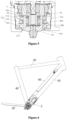
- the centrally mounted driving mechanism includes a motor 2, a planetary gear mechanism, a clutch 6, a bevel gear mechanism, a crankset support 11 and a crankset 13.
- the bevel gear mechanism includes a bevel gear support 8, a bevel gear driving end 9 and a bevel gear driven end 10.
- An output shaft of the motor 2 is in transmission connection with the planetary gear mechanism, and the motor 2 is configured to provide a driving force.
- the planetary gear mechanism includes a planetary gear 4 and a planetary gear output bracket 5.
- the planetary gear 4 is in transmission connection with the output shaft of the motor 2, the planetary gear output bracket 5 is inserted into the bevel gear support 8, and the clutch 6 is mounted between the planetary gear output bracket 5 and the bevel gear support 8.
- the bevel gear support 8 is connected to the bevel gear driving end 9, and the bevel gear driving end 9 is connected with the bevel gear driven end 10 configured for driving the crankset support 11 to rotate.
- the bevel gear driven end 10 is fixedly connected to or integrally formed with the crankset support 11.
- an output end of the planetary gear is connected to the bevel gear mechanism for speed reduction, and finally, the bevel gear mechanism is connected to the crankset support 11 to drive the crankset 13 to rotate, so as to assist the power-assisted bicycle.
- the bevel gear support 8 protrudes downward and is connected with the bevel gear driving end 9, and the interference fit with a certain theoretical length will be designed to ensure the strength and reliability of the connection.
- the length of the bevel gear driving end 9 and the bevel gear support 8 in close fit is greater than a certain theoretical value, in this case, the bevel gear is closer to a lower end of the motor in the axial direction, which leads to a larger size in the axial direction, and a separate positioning member is required for positioning the bevel gear driving end 9.
- a gasket 3 is provided on an upper end face of the planetary gear 4, and the gasket 3 is configured for preventing the planetary gear 4 from being worn and preventing the planetary gear 4 from playing in the axial direction thereof.
- the gasket 3 may be an annular-shaped gasket, and a central hole of the annular-shaped gasket is configured to allow the output shaft of the motor 2 to pass through.
- a holder of the conventional planetary gear 4 includes an upper holder and a lower holder, an end of a positioning shaft of the planetary gear 4 is in clearance fit with the upper holder, and another end of the positioning shaft of the planetary gear 4 is in interference fit with the lower holder.
- the gasket 3 is arranged between the housing 1 and the planetary gear 4, so that an upper end of the planetary gear 4 is not required to be provided with a holder, which further reduces the axial length of the whole structure.
- the positioning shaft of the planetary gear 4 is not required to be in clearance fit with the upper holder, which can avoid frictions, reduce losses and improve transmission efficiency.
- a centrally mounted driving mechanism for a power-assisted bicycle is provided according to a second not claimed embodiment of the present application.
- the difference between the second not claimed embodiment and the first preferred embodiment lies in a planetary gear output bracket 5A, a clutch 6A, a support assembly 7A, a bevel gear support 8A and a bevel gear driving end 9A.
- the planetary gear output bracket 5A is connected with the clutch 6A
- the clutch 6A is connected with the bevel gear support 8A located outside the clutch 6A
- the bevel gear support 8A is connected with the bevel gear driving end 9A
- the support assembly 7A surrounds the bevel gear support 8A.
- the bevel gear support 8A is cup-shaped.
- the bevel gear support 8A has a bottom 81A and a second annular protrusion 82A.
- a through hole is provided at a central portion of the bottom 81A.
- the bevel gear driving end 9A is fixedly connected with the bevel gear support 8A through the through hole by means of interference fit, welding or threaded connection.
- the planetary gear output bracket 5A has a shaft portion 51A, and the shaft portion 5A is inserted into the second annular protrusion 82A.
- the clutch 6A is arranged between the shaft portion 51A and the second annular protrusion 82A, and the clutch 6A is fitted to and connected with the shaft portion 51A and the second annular protrusion 82A, to realize the connection and separation of the bevel gear support 8A and the planetary gear output bracket 5A.
- a wedge-type clutch is preferably employed.
- a tail end of the bevel gear driving end 9A is provided with a transition structure to facilitate screwed installation, but the tail end of the bevel gear driving end 9A does not form strong connection with the planetary gear output bracket 5A.
- the tail end of the bevel gear driving end 9A is arranged to run through the bottom 81A, and a groove 52A is provided at a corresponding position of the shaft portion 51A.
- the tail end of the bevel gear driving end 9A extends into the groove 52A, and a gap is reserved between the tail end of the bevel gear driving end 9A and an inner wall of the groove 52A, so as to prevent interference during rotation.
- a sliding bearing 61A is provided at each of two ends of the clutch 6A, and the sliding bearing 61A is supported between the shaft portion 51A and the second annular protrusion 82A.
- the position-limiting of the planetary gear output bracket 5A is realized through the two sliding bearings 61A, thereby avoiding deflection.
- the support assembly 7A includes a first bearing 71A and a second bearing 72A arranged side by side.
- the first bearing 71A and the second bearing 72A are respectively arranged around a side portion of the second annular protrusion 82A, the first bearing 71A and the second bearing 72A are arranged to be spaced apart from each other, the first bearing 71A is arranged at an end of the side portion close to the planetary gear 4, and the second bearing 72A is arranged at another end of the side portion away from the planetary gear 4.
- first bearing 71A and the second bearing 72A are arranged to be spaced apart from each other, a distance between central support surfaces of the first bearing 71A and the second bearing 72A may be increased, which extends a support arm, thus providing more stable support for the bevel gear driving end 9A.
- a spacer 73A is arranged between the two bearings to realize separation.
- the spacer 73A may be a gasket surrounding the bevel gear support 8A or a side protrusion integrally formed with the bevel gear support 8A.
- an inner diameter of the first bearing 71A is the same as that of the second bearing 72A, and an outer diameter of the first bearing 71A is less than that of the second bearing 72A. That is, a size of the second bearing 72A is greater than that of the first bearing 71A.
- the support assembly 7A forms a cantilever support structure for the bevel gear driving end 9A. Compared with the first bearing 71A, the second bearing 72A is closer to the bevel gear driving end 9A, and the second bearing 72A provides a stronger supporting force.
- the distance between the central support surfaces of the first bearing 71A and the second bearing 72A may be further increased, which extends the support arm, and thus the support for the bevel gear driving end 9A is more stable.
- a power-assisted bicycle includes the centrally mounted driving mechanism described in the preferred embodiments.
- a frame of the power-assisted bicycle includes a top tube 20, a down tube 30, a seat tube 40, a chain stay 50 and a battery pack 60.
- the top tube 20, the down tube 30 and the seat tube 40 are sequentially connected end to end to form a triangle structure, and the chain stay 50 is connected with the down tube 30 to connect a rear wheel.
- the centrally mounted driving mechanism is mounted in the down tube 30, and the centrally mounted driving mechanism is located at an end of the down tube 30 connected with the seat tube 40.
- the battery pack 60 is also mounted in the down tube 30.
Landscapes
- Engineering & Computer Science (AREA)
- Chemical & Material Sciences (AREA)
- Combustion & Propulsion (AREA)
- Mechanical Engineering (AREA)
- Transportation (AREA)
- Retarders (AREA)
- Gear Transmission (AREA)
Claims (7)
- Ein zentral montierter Antriebsmechanismus der bei einem motorunterstützten Fahrrad verwendbar ist, umfassend:ein Gehäuse (1);einen Motor (2), der dazu eingerichtet ist, eine Antriebskraft bereitzustellen;ein Planetengetriebe, das mit einer Motorabtriebswelle in Übertragungsverbindung steht;ein Kegelradantriebsende (9, 9A);ein mit dem Kegelradantriebsende (9, 9A) kämmendes Kegelradabtriebsende (10), wobei das Kegelradabtriebsende (10) mit einem Kurbelsatz (13) verbunden ist, und wobei das Planetengetriebe ein Planetenrad (4) und einen Planetenradausgangsträger (5, 5A) umfasst; und wobeider zentral montierte Antriebsmechanismus ferner einen Kegelradträger (8, 8A) umfasst, der außerhalb des Planetenradausgangsträgers (5, 5A) gelagert ist, eine Kupplung (6) zwischen dem Planetenradausgangsträger (5, 5A) und dem Kegelradträger (8, 8A) vorgesehen ist, und der Planetenradausgangsträger (5, 5A) über die Kupplung (6) mit dem Kegelradträger (8, 8A) in Übertragungsverbindung steht;das Kegelradantriebsende (9, 9A) koaxial und fest mit dem Kegelradträger (8, 8A) verbunden ist, und eine Stützbaugruppe (7, 7A) außerhalb des Kegelradträgers (8, 8A) vorgesehen ist, und die Stützbaugruppe (7) dazu eingerichtet ist, den Planetenradausgangsträger (5, 5A) und das Kegelradantriebsende (9, 9A) zu stützen;der Planetenradausgangsträger (5, 5A) einen Schaftabschnitt (51, 51A) aufweist, der Kegelradträger (8, 8A) einen zweiten ringförmigen Vorsprung (82, 82A) aufweist, und der zweite ringförmige Vorsprung (82, 82A) dazu eingerichtet ist, den Schaftabschnitt (51, 51A) zu umgeben;die Kupplung (6, 6A) zwischen dem zweiten ringförmigen Vorsprung (82, 82A) und dem Planetenradausgangsträger (5, 5A) angeordnet ist, und die Kupplung (6, 6A) mit dem Kegelradträger (8, 8A) und mit dem Planetenradausgangsträger (5, 5A) montiert und gekoppelt ist, um eine Verbindung und Trennung zwischen dem Kegelradträger (8, 8A) und dem Planetenradausgangsträger (5, 5A) zu ermöglichen; unddie Stützbaugruppe (7, 7A) außerhalb des zweiten ringförmigen Vorsprungs (82, 82A) angeordnet ist; dadurch gekennzeichnet, dassder Kegelradträger (8) mit einem ersten ringförmigen Vorsprung (81) versehen ist, der auf einer Innenseite des zweiten ringförmigen Vorsprungs (82) angeordnet ist, das Kegelradantriebsende (9) mit einer Innenwand des ersten ringförmigen Vorsprungs (81) verbunden ist; und eine Nut (52) an einem vom Planetenrad (4) abgewandten Ende des Schaftabschnitts (51) vorgesehen ist, wobei der erste ringförmige Vorsprung (81) in die Nut (52) eingeführt ist, und ein Spalt zwischen dem ersten ringförmigen Vorsprung (81) und einer Innenwand der Nut (52) vorgesehen ist.
- Der zentral montierte Antriebsmechanismus nach Anspruch 1, wobei an jedem der beiden Enden der Kupplung (6A) ein Gleitlager (61A) vorgesehen ist, und wobei das Gleitlager (61A) zwischen dem Schaftabschnitt (51A) und dem zweiten ringförmigen Vorsprung (82A) abgestützt ist.
- Der zentral montierte Antriebsmechanismus nach Anspruch 1, wobei die Stützbaugruppe (7A) ein erstes Lager (71A) und ein zweites Lager (72A) umfasst, die voneinander beabstandet angeordnet sind, und wobei das erste Lager (71A) und das zweite Lager (72A) jeweils um einen Seitenabschnitt des zweiten ringförmigen Vorsprungs (82A) herum angeordnet sind.
- Der zentral montierte Antriebsmechanismus nach Anspruch 3, wobei das erste Lager (71A) an einem Ende des Seitenabschnitts angeordnet ist, das dem Planetenrad (4) näher liegt, und wobei das zweite Lager (72A) an einem anderen anderen Ende des Seitenabschnitts weg vom Planetenrad (4) angeordnet ist, wobei der Außendurchmesser des ersten Lagers (71A) kleiner als der des zweiten Lagers (72A) ist.
- Der zentral montierte Antriebsmechanismus nach Anspruch 1, ferner umfassend eine Kurbelsatzabstützung (11), wobei das Kegelradabtriebsende (10) über die Kurbelsatzabstützung (11) mit dem Kurbelsatz (13) verbunden ist; und wobei zwischen der Kurbelsatzabstützung (11) und dem Gehäuse (1) eine Lageranordnung vorgesehen ist, die zur Abstützung und Positionierung der Kurbelsatzabstützung (11) ausgebildet ist.
- Der zentral montierte Antriebsmechanismus nach Anspruch 1, wobei eine Dichtung (3) an einer oberen Stirnfläche des Planetenrades (4) vorgesehen ist, und wobei die Dichtung (3) dazu eingerichtet ist, eine Abnutzung des Planetenrades (4) und ein axiales Spiel des Planetenrades (4) zu verhindern.
- Ein motorunterstütztes Fahrrad, umfassend:den zentral montierten Antriebsmechanismus nach einem der Ansprüche 1 bis 6;ein Unterrohr (20); undein Batteriepaket (60), wobei der zentral montierte Antriebsmechanismus und das Batteriepaket (60) im Unterrohr (20) montiert sind.
Applications Claiming Priority (2)
| Application Number | Priority Date | Filing Date | Title |
|---|---|---|---|
| CN201911134539 | 2019-11-19 | ||
| CN202010304310.8A CN112896409B (zh) | 2019-11-19 | 2020-04-17 | 一种用于助力自行车的中置驱动机构及助力自行车 |
Publications (3)
| Publication Number | Publication Date |
|---|---|
| EP3825218A1 EP3825218A1 (de) | 2021-05-26 |
| EP3825218C0 EP3825218C0 (de) | 2025-06-25 |
| EP3825218B1 true EP3825218B1 (de) | 2025-06-25 |
Family
ID=73455578
Family Applications (1)
| Application Number | Title | Priority Date | Filing Date |
|---|---|---|---|
| EP20208011.5A Active EP3825218B1 (de) | 2019-11-19 | 2020-11-17 | Zentral montierter antriebsmechanismus für ein fahrrad und fahrrad mit hilfsantrieb |
Country Status (3)
| Country | Link |
|---|---|
| US (1) | US12403982B2 (de) |
| EP (1) | EP3825218B1 (de) |
| WO (1) | WO2021098500A1 (de) |
Families Citing this family (1)
| Publication number | Priority date | Publication date | Assignee | Title |
|---|---|---|---|---|
| DE102024128279A1 (de) * | 2024-09-30 | 2026-04-02 | Porsche Ebike Performance Gmbh | Antriebsvorrichtung für ein Elektrofahrrad und Baugruppe für eine Antriebsvorrichtung |
Citations (1)
| Publication number | Priority date | Publication date | Assignee | Title |
|---|---|---|---|---|
| US20190111998A1 (en) * | 2017-10-13 | 2019-04-18 | Shimano Inc. | Bicycle drive unit |
Family Cites Families (15)
| Publication number | Priority date | Publication date | Assignee | Title |
|---|---|---|---|---|
| JP2634121B2 (ja) * | 1992-03-06 | 1997-07-23 | ヤマハ発動機株式会社 | 電動モータ付き自転車およびそのモータ制御方法 |
| US5829546A (en) * | 1996-07-22 | 1998-11-03 | Merida Industry Co., Ltd. | Electrical drive for a bicycle |
| US6554730B1 (en) * | 1997-01-29 | 2003-04-29 | Nsk Ltd. | Auxiliary device for bicycle with traction roller type gear |
| DE29911858U1 (de) | 1999-07-08 | 1999-10-07 | Lin, Chun San, Tachia Town, Taichung | Antriebseinrichtung für ein elektrisches Fahrrad |
| EP1070660A1 (de) | 1999-07-22 | 2001-01-24 | Merida Industry Co., Ltd. | Elektrischer Antrieb für ein Fahrrad |
| US8646560B2 (en) * | 2010-01-22 | 2014-02-11 | Foster Assets Corporation | Motor having an integrated torque sensor |
| CN205327312U (zh) | 2015-12-30 | 2016-06-22 | 天津迪思科博科技发展有限公司 | 具有倒刹车触发机构的电动自行车中置电机 |
| CN105449921B (zh) * | 2015-12-30 | 2017-10-27 | 天津迪思科博科技发展有限公司 | 隐藏型中置电机及安装隐藏型中置电机的电动自行车 |
| CN206691312U (zh) * | 2016-09-07 | 2017-12-01 | 新安乃达驱动技术(上海)股份有限公司 | 电动自行车及其中置驱动系统 |
| US10137959B2 (en) * | 2016-10-26 | 2018-11-27 | Chun-Hsiang Liu | Electric bicycle drive assembly with torque detection |
| TWI635022B (zh) * | 2017-03-30 | 2018-09-11 | 黃永松 | 離合式自行車電力驅動裝置 |
| JP6787866B2 (ja) | 2017-10-13 | 2020-11-18 | 株式会社シマノ | 自転車用コンポーネント |
| CN208085921U (zh) | 2017-12-29 | 2018-11-13 | 门德君 | 隐藏式自行车助力配件及构成自行车 |
| JP7219013B2 (ja) * | 2018-04-06 | 2023-02-07 | 株式会社シマノ | 人力駆動車用コンポーネント |
| CN110282067A (zh) | 2019-08-12 | 2019-09-27 | 苏州万佳电器有限公司 | 一种中置驱动机构及具有该中置驱动机构的助力自行车 |
-
2020
- 2020-11-03 US US17/776,526 patent/US12403982B2/en active Active
- 2020-11-03 WO PCT/CN2020/126022 patent/WO2021098500A1/zh not_active Ceased
- 2020-11-17 EP EP20208011.5A patent/EP3825218B1/de active Active
Patent Citations (1)
| Publication number | Priority date | Publication date | Assignee | Title |
|---|---|---|---|---|
| US20190111998A1 (en) * | 2017-10-13 | 2019-04-18 | Shimano Inc. | Bicycle drive unit |
Also Published As
| Publication number | Publication date |
|---|---|
| EP3825218C0 (de) | 2025-06-25 |
| US12403982B2 (en) | 2025-09-02 |
| EP3825218A1 (de) | 2021-05-26 |
| US20220379996A1 (en) | 2022-12-01 |
| WO2021098500A1 (zh) | 2021-05-27 |
Similar Documents
| Publication | Publication Date | Title |
|---|---|---|
| US10000255B2 (en) | Bicycle drive unit and bicycle equipped with the drive unit | |
| US10661858B2 (en) | Electric-motor-assisted bicycle | |
| KR20190022743A (ko) | 자전거용 미드 모터 및 전동 어시스트 자전거 | |
| CN217216272U (zh) | 驱动装置及电动车辆 | |
| EP3825218B1 (de) | Zentral montierter antriebsmechanismus für ein fahrrad und fahrrad mit hilfsantrieb | |
| CN105083463A (zh) | 自行车用驱动单元 | |
| EP4393807A1 (de) | Nabenanordnung und fahrrad | |
| CN212766630U (zh) | 一种助力自行车的中置驱动机构 | |
| CN211663398U (zh) | 一种中置驱动装置和具有该装置的自行车 | |
| CN112896409B (zh) | 一种用于助力自行车的中置驱动机构及助力自行车 | |
| CN213064584U (zh) | 双轴同步输出永磁直流电机 | |
| CN212766631U (zh) | 一种用于助力自行车的中置驱动机构及助力自行车 | |
| CN220098451U (zh) | 双电机同轴的一体化重载立式动力轮和应用其的无人叉车 | |
| CN220857821U (zh) | 中置电机及电动自行车 | |
| CN216762053U (zh) | 采用二级齿轮减速机构的紧凑中置电机 | |
| EP4249360B1 (de) | Elektrisches hilfsmotormodul und reduzierstruktur | |
| WO2023236046A1 (en) | Power-assisted drive assembly | |
| CN217216273U (zh) | 驱动装置及电动车辆 | |
| CN214743073U (zh) | 一种前轮双驱叉车用轮边减速机构 | |
| CN214823908U (zh) | 中置电机传动机构、电动助力车驱动系统及电动助力车 | |
| CN117318379A (zh) | 电动自行车中置电机及工作方法 | |
| CN212785045U (zh) | 变速电机 | |
| CN113525583B (zh) | 一种助力自行车的中置驱动机构 | |
| CN224184101U (zh) | 一种搬运车及其手电快速切换的驱动总成 | |
| JP7593039B2 (ja) | 駆動装置、および、電動車 |
Legal Events
| Date | Code | Title | Description |
|---|---|---|---|
| PUAI | Public reference made under article 153(3) epc to a published international application that has entered the european phase |
Free format text: ORIGINAL CODE: 0009012 |
|
| STAA | Information on the status of an ep patent application or granted ep patent |
Free format text: STATUS: THE APPLICATION HAS BEEN PUBLISHED |
|
| AK | Designated contracting states |
Kind code of ref document: A1 Designated state(s): AL AT BE BG CH CY CZ DE DK EE ES FI FR GB GR HR HU IE IS IT LI LT LU LV MC MK MT NL NO PL PT RO RS SE SI SK SM TR |
|
| STAA | Information on the status of an ep patent application or granted ep patent |
Free format text: STATUS: REQUEST FOR EXAMINATION WAS MADE |
|
| 17P | Request for examination filed |
Effective date: 20211125 |
|
| RBV | Designated contracting states (corrected) |
Designated state(s): AL AT BE BG CH CY CZ DE DK EE ES FI FR GB GR HR HU IE IS IT LI LT LU LV MC MK MT NL NO PL PT RO RS SE SI SK SM TR |
|
| STAA | Information on the status of an ep patent application or granted ep patent |
Free format text: STATUS: EXAMINATION IS IN PROGRESS |
|
| 17Q | First examination report despatched |
Effective date: 20230317 |
|
| GRAP | Despatch of communication of intention to grant a patent |
Free format text: ORIGINAL CODE: EPIDOSNIGR1 |
|
| STAA | Information on the status of an ep patent application or granted ep patent |
Free format text: STATUS: GRANT OF PATENT IS INTENDED |
|
| INTG | Intention to grant announced |
Effective date: 20250117 |
|
| GRAS | Grant fee paid |
Free format text: ORIGINAL CODE: EPIDOSNIGR3 |
|
| GRAA | (expected) grant |
Free format text: ORIGINAL CODE: 0009210 |
|
| STAA | Information on the status of an ep patent application or granted ep patent |
Free format text: STATUS: THE PATENT HAS BEEN GRANTED |
|
| AK | Designated contracting states |
Kind code of ref document: B1 Designated state(s): AL AT BE BG CH CY CZ DE DK EE ES FI FR GB GR HR HU IE IS IT LI LT LU LV MC MK MT NL NO PL PT RO RS SE SI SK SM TR |
|
| REG | Reference to a national code |
Ref country code: GB Ref legal event code: FG4D |
|
| REG | Reference to a national code |
Ref country code: CH Ref legal event code: EP |
|
| REG | Reference to a national code |
Ref country code: DE Ref legal event code: R096 Ref document number: 602020053226 Country of ref document: DE |
|
| REG | Reference to a national code |
Ref country code: CH Ref legal event code: EP |
|
| REG | Reference to a national code |
Ref country code: IE Ref legal event code: FG4D |
|
| U01 | Request for unitary effect filed |
Effective date: 20250716 |
|
| U07 | Unitary effect registered |
Designated state(s): AT BE BG DE DK EE FI FR IT LT LU LV MT NL PT RO SE SI Effective date: 20250723 |
|
| PG25 | Lapsed in a contracting state [announced via postgrant information from national office to epo] |
Ref country code: NO Free format text: LAPSE BECAUSE OF FAILURE TO SUBMIT A TRANSLATION OF THE DESCRIPTION OR TO PAY THE FEE WITHIN THE PRESCRIBED TIME-LIMIT Effective date: 20250925 Ref country code: GR Free format text: LAPSE BECAUSE OF FAILURE TO SUBMIT A TRANSLATION OF THE DESCRIPTION OR TO PAY THE FEE WITHIN THE PRESCRIBED TIME-LIMIT Effective date: 20250926 |
|
| PG25 | Lapsed in a contracting state [announced via postgrant information from national office to epo] |
Ref country code: HR Free format text: LAPSE BECAUSE OF FAILURE TO SUBMIT A TRANSLATION OF THE DESCRIPTION OR TO PAY THE FEE WITHIN THE PRESCRIBED TIME-LIMIT Effective date: 20250625 |
|
| PG25 | Lapsed in a contracting state [announced via postgrant information from national office to epo] |
Ref country code: RS Free format text: LAPSE BECAUSE OF FAILURE TO SUBMIT A TRANSLATION OF THE DESCRIPTION OR TO PAY THE FEE WITHIN THE PRESCRIBED TIME-LIMIT Effective date: 20250925 |
|
| REG | Reference to a national code |
Ref country code: CH Ref legal event code: U11 Free format text: ST27 STATUS EVENT CODE: U-0-0-U10-U11 (AS PROVIDED BY THE NATIONAL OFFICE) Effective date: 20251211 |
|
| U20 | Renewal fee for the european patent with unitary effect paid |
Year of fee payment: 6 Effective date: 20251127 |
|
| PG25 | Lapsed in a contracting state [announced via postgrant information from national office to epo] |
Ref country code: IS Free format text: LAPSE BECAUSE OF FAILURE TO SUBMIT A TRANSLATION OF THE DESCRIPTION OR TO PAY THE FEE WITHIN THE PRESCRIBED TIME-LIMIT Effective date: 20251025 |
|
| PGFP | Annual fee paid to national office [announced via postgrant information from national office to epo] |
Ref country code: GB Payment date: 20251127 Year of fee payment: 6 |
|
| PG25 | Lapsed in a contracting state [announced via postgrant information from national office to epo] |
Ref country code: SM Free format text: LAPSE BECAUSE OF FAILURE TO SUBMIT A TRANSLATION OF THE DESCRIPTION OR TO PAY THE FEE WITHIN THE PRESCRIBED TIME-LIMIT Effective date: 20250625 |
|
| PGFP | Annual fee paid to national office [announced via postgrant information from national office to epo] |
Ref country code: CH Payment date: 20251211 Year of fee payment: 6 |
|
| PG25 | Lapsed in a contracting state [announced via postgrant information from national office to epo] |
Ref country code: CZ Free format text: LAPSE BECAUSE OF FAILURE TO SUBMIT A TRANSLATION OF THE DESCRIPTION OR TO PAY THE FEE WITHIN THE PRESCRIBED TIME-LIMIT Effective date: 20250625 |
|
| PG25 | Lapsed in a contracting state [announced via postgrant information from national office to epo] |
Ref country code: PL Free format text: LAPSE BECAUSE OF FAILURE TO SUBMIT A TRANSLATION OF THE DESCRIPTION OR TO PAY THE FEE WITHIN THE PRESCRIBED TIME-LIMIT Effective date: 20250625 |
|
| PG25 | Lapsed in a contracting state [announced via postgrant information from national office to epo] |
Ref country code: SK Free format text: LAPSE BECAUSE OF FAILURE TO SUBMIT A TRANSLATION OF THE DESCRIPTION OR TO PAY THE FEE WITHIN THE PRESCRIBED TIME-LIMIT Effective date: 20250625 |
|
| PG25 | Lapsed in a contracting state [announced via postgrant information from national office to epo] |
Ref country code: ES Free format text: LAPSE BECAUSE OF FAILURE TO SUBMIT A TRANSLATION OF THE DESCRIPTION OR TO PAY THE FEE WITHIN THE PRESCRIBED TIME-LIMIT Effective date: 20250625 |
|
| PLBE | No opposition filed within time limit |
Free format text: ORIGINAL CODE: 0009261 |
|
| STAA | Information on the status of an ep patent application or granted ep patent |
Free format text: STATUS: NO OPPOSITION FILED WITHIN TIME LIMIT |