EP3822037A1 - Impact device assembly - Google Patents
Impact device assembly Download PDFInfo
- Publication number
- EP3822037A1 EP3822037A1 EP19209451.4A EP19209451A EP3822037A1 EP 3822037 A1 EP3822037 A1 EP 3822037A1 EP 19209451 A EP19209451 A EP 19209451A EP 3822037 A1 EP3822037 A1 EP 3822037A1
- Authority
- EP
- European Patent Office
- Prior art keywords
- impact
- hammer
- anvil
- rebound
- absorber element
- Prior art date
- Legal status (The legal status is an assumption and is not a legal conclusion. Google has not performed a legal analysis and makes no representation as to the accuracy of the status listed.)
- Withdrawn
Links
Images

Classifications
-
- B—PERFORMING OPERATIONS; TRANSPORTING
- B25—HAND TOOLS; PORTABLE POWER-DRIVEN TOOLS; MANIPULATORS
- B25D—PERCUSSIVE TOOLS
- B25D17/00—Details of, or accessories for, portable power-driven percussive tools
- B25D17/24—Damping the reaction force
-
- B—PERFORMING OPERATIONS; TRANSPORTING
- B25—HAND TOOLS; PORTABLE POWER-DRIVEN TOOLS; MANIPULATORS
- B25D—PERCUSSIVE TOOLS
- B25D17/00—Details of, or accessories for, portable power-driven percussive tools
- B25D17/06—Hammer pistons; Anvils ; Guide-sleeves for pistons
-
- B—PERFORMING OPERATIONS; TRANSPORTING
- B25—HAND TOOLS; PORTABLE POWER-DRIVEN TOOLS; MANIPULATORS
- B25D—PERCUSSIVE TOOLS
- B25D2217/00—Details of, or accessories for, portable power-driven percussive tools
- B25D2217/0011—Details of anvils, guide-sleeves or pistons
- B25D2217/0015—Anvils
-
- B—PERFORMING OPERATIONS; TRANSPORTING
- B25—HAND TOOLS; PORTABLE POWER-DRIVEN TOOLS; MANIPULATORS
- B25D—PERCUSSIVE TOOLS
- B25D2217/00—Details of, or accessories for, portable power-driven percussive tools
- B25D2217/0011—Details of anvils, guide-sleeves or pistons
- B25D2217/0019—Guide-sleeves
-
- B—PERFORMING OPERATIONS; TRANSPORTING
- B25—HAND TOOLS; PORTABLE POWER-DRIVEN TOOLS; MANIPULATORS
- B25D—PERCUSSIVE TOOLS
- B25D2250/00—General details of portable percussive tools; Components used in portable percussive tools
- B25D2250/121—Housing details
-
- B—PERFORMING OPERATIONS; TRANSPORTING
- B25—HAND TOOLS; PORTABLE POWER-DRIVEN TOOLS; MANIPULATORS
- B25D—PERCUSSIVE TOOLS
- B25D2250/00—General details of portable percussive tools; Components used in portable percussive tools
- B25D2250/131—Idling mode of tools
Definitions
- the present invention relates to a hammer drill and / or chisel hammer with a drive motor, an impact mechanism and a tool holder for receiving a tool.
- the striking mechanism has a striker that is axially displaceable in a striker guide and that acts on the tool.
- the hammer mechanism is equipped with an idle shock absorber element that acts between the anvil and the tool holder.
- the hammer mechanism has a guide housing which surrounds the anvil and / or the tool holder at least in sections.
- Idle shock absorber elements and rebound shock absorber elements which are preferably designed as elastomer damping elements, are used to keep force peaks on downstream components and vibrations as low as possible.
- the striker hits a typically provided impact disc after each impact and is intercepted by the impact shock absorption element.
- a blank impact damping element is typically used to protect the downstream components from a peak force of the blank impact.
- a blank impact damping of the idle impact absorber element influences the return speed of the anvil after a blank impact and thus also the shutdown behavior of the hammer.
- the object is achieved in that an additional idle shock absorber element is provided, which acts between the tool holder and the guide housing.
- the invention has the advantage that a comparatively low Döpper return flight speed can be achieved by two damping elements working against one another. While the idle impact absorber element in the course of a return flight movement of the striker, ie after the Empty impact, rebound, springs in the additional empty impact damper element acting between the tool holder and the guide housing, so that the anvil is only accelerated back comparatively slightly. This in turn reduces the load on the tool holder comparatively.
- the tool holder is movable in the axial direction relative to the guide housing and / or is arranged at least in sections within the guide housing. It has been found to be advantageous if the striking mechanism has a rebound shock absorber element and an additional rebound shock absorber element.
- the impact shock absorber element preferably acts between the striker and the guide housing. It has been found to be advantageous if the additional rebound shock absorber element is arranged so as to act between the tool holder and the guide housing.
- An oscillating mounting of the tool holder can be achieved through the interaction of the additional idle impact absorber element and additional impact impact absorber element, whereby a not inconsiderable proportion of the impact energy of the anvil can be swung out.
- the additional idle impact absorber element and / or the additional impact impact absorber element are spaced further apart from the anvil in the radial direction than the idle impact absorber element and / or the impact impact absorber element.
- the additional idle shock absorber element can be supported in the axial direction by a guide bearing.
- a force is introduced from the tool holder into the unit of additional idle impact damper element and additional rebound shock absorber element through a ring or pin protruding in the radial direction from the tool holder. It has been found to be advantageous if the ring or pin, in relation to the axial direction of the anvil, engages between the additional idle impact damper element and the additional impact shock absorber element. The ring or pin can be clamped in the axial direction between the additional idle impact absorber element and the additional rebound impact absorber element.
- the anvil is assigned a contact piece which is arranged for contacting a blank impact stop surface on the one hand and for contacting a rebound impact stop surface on the other hand. It has been found to be advantageous if the blank impact stop surface is formed on a blank impact stop ring encompassed by the tool holder and / or the rebound impact stop surface is formed on a rebound impact stop ring encompassed by the tool receptacle.
- the striking mechanism has an idle impact wedge ring and / or a rebound impact wedge ring.
- the idle impact wedge ring can be arranged between a first bearing of the striker guide and the idle impact damper element. It has been found to be advantageous if the rebound impact wedge ring is arranged between a second bearing of the anvil guide and the rebound impact damper element.
- the first and / or the second bearing can be designed as a slide bearing or as a roller bearing.
- the idle impact wedge ring is supported exclusively against the first bearing on its side facing away from the idle impact damper element and in the axial direction.
- the rebound impact wedge ring can be supported on its side facing away from the rebound impact damper element and in the axial direction exclusively against second bearings.
- the contact piece is designed differently from the anvil.
- the contact piece can advantageously be clamped elastically in the axial direction between the idle impact absorber element and the rebound impact absorber element. It has been found to be advantageous if the contact piece is movable in an axial direction relative to the striker.
- the anvil has a groove extending in the axial direction. The contact piece is particularly preferably permanently in engagement with the groove.
- the contact piece can be formed in one piece with the striker. It has been found to be advantageous if the idle impact damper element, the rebound impact damper element, the additional idle impact absorber element and / or the additional impact impact absorber element are designed as elastomer bodies.
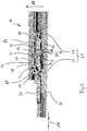
- FIG Fig. 1 A preferred embodiment of a hammer drill and / or chisel hammer 100 according to the invention is shown in FIG Fig. 1 shown.
- the hammer drill and / or chisel hammer 100 is equipped with a drive motor 70, a hammer mechanism 10 and a tool holder 50 for receiving a tool 110.
- the hammer mechanism 10 and the drive motor 70 are arranged within a housing 90 of the hammer drill and / or chisel hammer 100.
- the striking mechanism 10 has a striker 30 which can be displaced in an axial direction AR in a striker guide 20 and acts on the tool 110.
- the anvil guide 20 is implemented by a first bearing 21 and a second bearing 23 (embodied here as an example as roller bearings), which are each supported against the tool holder 50 both in the radial direction RR and in the axial direction AR.
- the hammer mechanism 10 has an idle impact damper element 11 which acts between the anvil 30 and the tool holder 50 (mediated by the idle impact stop ring 56).
- the striking mechanism 10 also has a guide housing 80 which engages around the anvil 30 and the tool holder 50 at least in sections.
- an additional idle impact damper element 31 is provided, which acts between the tool holder 50 and the guide housing 80.
- the tool holder 50 is movable in the axial direction AR relative to the guide housing 80 and is arranged at least in sections within the guide housing 80. If the tool holder 50 moves further out of the guide housing 80 in the axial direction AR, ie in Fig. 1 to the left, the elastic additional idle impact damper element 31 is compressed.
- the hammer mechanism 10 is equipped with an elastic impact shock absorber element 13 and an elastic additional impact shock absorber element 33.
- the additional impact shock absorber element 33 acts between the tool holder 50 and the guide housing 80. In this case, a force is introduced from the tool holder 50 into the unit of additional idle impact absorber element 31 and additional impact impact absorber element 33 through a ring 51 protruding from the tool holder in the radial direction RR the tool holder 50 moves further in the axial direction AR into the guide housing 80, ie in Fig.
- the elastic additional idle impact damper element 31 is relieved and the additional impact shock absorber element 33 is compressed.
- the ring 51 can be clamped in the axial direction AR between the additional idle impact absorber element 31 and the additional impact impact absorber element 33. Again Fig. 1 can be taken, engages the ring 51, based on the axial direction AR, between the additional idle impact damper element 31 and additional impact shock absorber element 33.
- a contact piece 35 is assigned to the anvil 30, which is arranged for contacting a blank impact stop surface 12 on the one hand and for contacting a rebound impact stop surface 14 on the other hand.
- the contact piece 35 is formed in one piece with the striker 30.
- the idle impact stop surface 12 is formed on the idle impact stop ring 56 encompassed by the tool holder 50.
- the impact impact stop surface 14 is in turn formed on the impact impact stop ring 55 encompassed by the tool holder 50.
- FIG Fig. 2 Another preferred embodiment of a striking mechanism 10 is shown in FIG Fig. 2 shown.
- the striking mechanism 10 has a striker 30 which can be displaced in an axial direction AR in a striker guide 20.
- the anvil guide 20 is implemented by a first bearing 21 and a second bearing 23 (embodied here as an example as roller bearings), which are each supported against the tool holder 50 both in the radial direction RR and in the axial direction AR.
- the contact piece 35 is designed differently from the striker 30.
- the anvil 30 has a groove 37 which extends in the axial direction AR and in which the contact piece 35 can slide in the axial direction AR.
- the contact piece 35 is movable both with respect to the striker 30 and with respect to the tool holder 50, each seen in the axial direction AR.
- the contact piece 35 is permanently in engagement with the groove 37.
- the striking mechanism 10 of the Fig. 2 has an idle impact damper element 11 which, mediated by an idle impact wedge ring 57 and a first bearing 21 on the one hand and through an idle impact stop ring 56 and the contact piece 35 on the other, acts between the anvil 30 and the tool holder 50. Furthermore, a rebound shock absorber element 13 is provided which, mediated by a rebound impact wedge ring 58 and a second bearing 21 on the one hand and through Bounce stop ring 55 and the contact piece 35 on the other hand, between the striker 30 and the guide housing 50 acts.
- the idle impact wedge ring 57 is arranged between the first bearing 21 of the anvil guide 20 and the idle impact damper element 10.
- the impact impact wedge ring 58 is arranged between the second bearing 23 of the striker guide 20 and the impact impact damper element 13.
- the idle impact wedge ring 57 is supported on its side facing away from the idle impact damper element 10 and in the axial direction AR exclusively against the first bearing 21.
- the rebound impact wedge ring 58 is supported on its side facing away from the rebound impact damper element 13 and in the axial direction exclusively against the second bearing 23.
- the contact piece 35 different from the striker 30 is elastically clamped in the axial direction AR between the idle impact absorber element 11 and the rebound impact absorber element 13. To this extent, when the striking mechanism 10 is in operation, there is no “classic” stop of the contact piece 35 on the idle impact stop ring 56 or the rebound impact stop ring 55.
- an additional idle impact damper element 31 is provided, which acts between the tool holder 50 and the guide housing 80.
- the additional idle impact damper element 31 is supported in the axial direction AR by a guide bearing 85.
- the hammer mechanism 10 is equipped with an elastic impact shock absorber element 13 and an additional elastic impact shock absorber element 33.
- the impact shock absorber element 13 is between the anvil 30 and the guide housing 50, mediated by the impact impact stop ring 55, the impact impact wedge ring 58 and the contact piece 35 effective.
- the additional impact shock absorber element 33 acts between the tool holder 50 and the guide housing 80. In this case, force is introduced from the tool holder 50 into the unit of additional idle impact absorber element 31 and additional impact impact absorber element 33 through a ring 51 protruding from the tool holder in the radial direction RR.
Abstract
Bohr- und/oder Meisselhammer (100) mit einem Antriebsmotor (70), einem Schlagwerk (10) und einer Werkzeugaufnahme (50) zur Aufnahme eines Werkzeugs (110), wobei das Schlagwerk (10) einen in einer Döpperführung (20) axial verschiebbaren und auf das Werkzeug (110) einwirkenden Döpper (30) aufweist, wobei das Schlagwerk (10) ein Leerschlagdämpferelement (11) aufweist, das zwischen dem Döpper (30) und der Werkzeugaufnahme (50) wirkt, und wobei das Schlagwerk ein Führungsgehäuse (80) aufweist, das den Döpper (30) und/oder die Werkzeugaufnahme (50) zumindest abschnittsweise umgreift, wobei ein Zusatz-Leerschlagdämpferelement (31) vorgesehen ist, das zwischen der Werkzeugaufnahme (50) und dem Führungsgehäuse (80) wirkt.Hammer drill and / or chisel hammer (100) with a drive motor (70), an impact mechanism (10) and a tool holder (50) for receiving a tool (110), the impact mechanism (10) being axially displaceable in an anvil guide (20) and has an anvil (30) acting on the tool (110), the hammer mechanism (10) having a dead impact damper element (11) which acts between the anvil (30) and the tool holder (50), and wherein the hammer mechanism has a guide housing (80 ) which surrounds the anvil (30) and / or the tool holder (50) at least in sections, an additional idle impact damper element (31) being provided which acts between the tool holder (50) and the guide housing (80).
Description
Die vorliegende Erfindung betrifft einen Bohr- und/oder Meisselhammer mit einem Antriebsmotor, einem Schlagwerk und einer Werkzeugaufnahme zur Aufnahme eines Werkzeugs. Das Schlagwerk weist einen in einer Döpperführung axial verschiebbaren und auf das Werkzeug einwirkenden Döpper auf. Das Schlagwerk ist ausgestattet mit einem Leerschlagdämpferelement, das zwischen dem Döpper und der Werkzeugaufnahme wirkt. Das Schlagwerk weist ein Führungsgehäuse auf, das den Döpper und/oder die Werkzeugaufnahme zumindest abschnittsweise umgreift.The present invention relates to a hammer drill and / or chisel hammer with a drive motor, an impact mechanism and a tool holder for receiving a tool. The striking mechanism has a striker that is axially displaceable in a striker guide and that acts on the tool. The hammer mechanism is equipped with an idle shock absorber element that acts between the anvil and the tool holder. The hammer mechanism has a guide housing which surrounds the anvil and / or the tool holder at least in sections.
Bohr- und/oder Meisselhammer der eingangs genannten Art sind grundsätzlich aus dem Stand der Technik bekannt.Hammer drills and / or chisel hammers of the type mentioned are basically known from the prior art.
Leerschlagdämpferelemente und Prellschlagdämpferelemente, die vorzugsweise als Elastomer-Dämpfelemente ausgebildet sind, werden eingesetzt um Kraftspitzen auf nachgelagerte Bauteile und Vibrationen so gering wie möglich zu halten. Wenn sich das Schlagwerk im Arbeitspunkt befindet, stößt der Döpper nach jedem Schlag auf eine typischerweise vorgesehene Prellschlagscheibe und wird durch das Prellschlagdämpfelement abgefangen.Idle shock absorber elements and rebound shock absorber elements, which are preferably designed as elastomer damping elements, are used to keep force peaks on downstream components and vibrations as low as possible. When the hammer mechanism is at the operating point, the striker hits a typically provided impact disc after each impact and is intercepted by the impact shock absorption element.
Bei einer zu geringen Anpresskraft oder dem Wegbruch von zu bearbeiteten Beton/Stein können Leerschläge auftreten. Dies bedeutet, dass Schläge mit voller Schlagenergie durch den Hammer und insbesondere die Werkzeugaufnahme selber abgefangen werden müssen. Um die nachgelagerten Bauteile vor einer Kraftspitze des Leerschlags zu schützen, kommt typischerweise ein Leerschlagdämpfelement zum Einsatz. Eine Leerschlagdämpfung des Leerschlagdämpferelements beeinflusst die Rückfluggeschwindigkeit des Döppers nach einem Leerschlag und damit auch das Abstellverhalten des Hammers.If the contact pressure is too low or if the concrete / stone to be processed breaks away, blank spaces can occur. This means that blows must be absorbed with full impact energy by the hammer and in particular the tool holder itself. A blank impact damping element is typically used to protect the downstream components from a peak force of the blank impact. A blank impact damping of the idle impact absorber element influences the return speed of the anvil after a blank impact and thus also the shutdown behavior of the hammer.
Es ist Aufgabe der vorliegenden Erfindung einen Bohr- und/oder Meisselhammer bereitzustellen, bei dem eine Belastung der Werkzeugaufnahme vergleichsweise reduziert ist.It is the object of the present invention to provide a hammer drill and / or chisel hammer in which the load on the tool holder is comparatively reduced.
Die Aufgabe wird dadurch gelöst, dass ein Zusatz-Leerschlagdämpferelement vorgesehen ist, das zwischen der Werkzeugaufnahme und dem Führungsgehäuse wirkt. Die Erfindung hat den Vorteil, dass eine vergleichsweise niedrige Döpper-Rückfluggeschwindigkeit durch gegeneinander Arbeiten zweier Dämpfelemente erreicht werden kann. Während das Leerschlagdämpferelement im Zuge einer Rückflugbewegung des Döppers, d.h. nach dem Leerschlag, ausfedert, federt das zwischen der Werkzeugaufnahme und dem Führungsgehäuse wirkende Zusatz-Leerschlagdämpferelement ein, sodass der Döpper nur vergleichsweise geringfügig zurück beschleunigt wird. Dadurch wird wiederum eine Belastung der Werkzeugaufnahme vergleichsweise reduziert.The object is achieved in that an additional idle shock absorber element is provided, which acts between the tool holder and the guide housing. The invention has the advantage that a comparatively low Döpper return flight speed can be achieved by two damping elements working against one another. While the idle impact absorber element in the course of a return flight movement of the striker, ie after the Empty impact, rebound, springs in the additional empty impact damper element acting between the tool holder and the guide housing, so that the anvil is only accelerated back comparatively slightly. This in turn reduces the load on the tool holder comparatively.
In einer besonders bevorzugten Ausgestaltung ist die Werkzeugaufnahme in axialer Richtung relativ zum Führungsgehäuse beweglich und/oder zumindest abschnittsweise innerhalb des Führungsgehäuses angeordnet. Es hat sich als vorteilhaft herausgestellt, wenn das Schlagwerk ein Prellschlagdämpferelement und ein Zusatz-Prellschlagdämpferelement aufweist. Das Prellschlagdämpferelement wirkt vorzugsweise zwischen dem Döpper und dem Führungsgehäuse. Es hat sich als vorteilhaft herausgestellt, wenn das Zusatz-Prellschlagdämpferelement zwischen der Werkzeugaufnahme und dem Führungsgehäuse wirkend angeordnet ist. Durch ein Zusammenwirken von Zusatz-Leerschlagdämpferelement und Zusatz-Prellschlagdämpferelement kann eine schwingende Lagerung der Werkzeugaufnahme erreicht werden, wodurch bereits ein nicht unerheblicher Anteil der Schlagenergie des Döppers ausgeschwungen werden kann.In a particularly preferred embodiment, the tool holder is movable in the axial direction relative to the guide housing and / or is arranged at least in sections within the guide housing. It has been found to be advantageous if the striking mechanism has a rebound shock absorber element and an additional rebound shock absorber element. The impact shock absorber element preferably acts between the striker and the guide housing. It has been found to be advantageous if the additional rebound shock absorber element is arranged so as to act between the tool holder and the guide housing. An oscillating mounting of the tool holder can be achieved through the interaction of the additional idle impact absorber element and additional impact impact absorber element, whereby a not inconsiderable proportion of the impact energy of the anvil can be swung out.
Es hat sich als vorteilhaft herausgestellt, wenn das Zusatz-Leerschlagdämpferelement und/oder das Zusatz-Prellschlagdämpferelement in radialer Richtung weiter vom Döpper beabstandet sind, als Leerschlagdämpferelement und/oder das Prellschlagdämpferelement. Gegenüber dem Führungsgehäuse kann das Zusatz-Leerschlagdämpferelement in axialer Richtung durch ein Führungslager abgestützt sein.It has been found to be advantageous if the additional idle impact absorber element and / or the additional impact impact absorber element are spaced further apart from the anvil in the radial direction than the idle impact absorber element and / or the impact impact absorber element. Compared to the guide housing, the additional idle shock absorber element can be supported in the axial direction by a guide bearing.
In einer besonders bevorzugten Ausgestaltung erfolgt ein Krafteintrag von der Werkzeugaufnahme in die Einheit aus Zusatz-Leerschlagdämpferelement und Zusatz-Prellschlagdämpferelement durch einen in radialer Richtung von der Werkzeugaufnahme abstehenden Ring oder Zapfen. Es hat sich als vorteilhaft herausgestellt, wenn der Ring oder Zapfen, bezogen auf die axiale Richtung des Döppers, zwischen Zusatz-Leerschlagdämpferelement und Zusatz-Prellschlagdämpferelement eingreift. Der Ring oder Zapfen kann in axialer Richtung zwischen dem Zusatz-Leerschlagdämpferelement und dem Zusatz-Prellschlagdämpferelement eingespannt sein.In a particularly preferred embodiment, a force is introduced from the tool holder into the unit of additional idle impact damper element and additional rebound shock absorber element through a ring or pin protruding in the radial direction from the tool holder. It has been found to be advantageous if the ring or pin, in relation to the axial direction of the anvil, engages between the additional idle impact damper element and the additional impact shock absorber element. The ring or pin can be clamped in the axial direction between the additional idle impact absorber element and the additional rebound impact absorber element.
In einer besonders bevorzugten Ausgestaltung ist dem Döpper ein Kontaktstück zugeordnet, das zum Kontaktieren einer Leerschlag-Anschlagsfläche einerseits und zum Kontaktieren an eine Prellschlag-Anschlagsfläche andererseits angeordnet ist. Es hat sich als vorteilhaft herausgestellt, wenn die Leerschlag-Anschlagsfläche an einem von der Werkzeugaufnahme umfassten Leerschlag-Anschlagring ausgebildet ist und/oder die Prellschlag-Anschlagsfläche an einem von der Werkzeugaufnahme umfassten Prellschlag-Anschlagring ausgebildet ist.In a particularly preferred embodiment, the anvil is assigned a contact piece which is arranged for contacting a blank impact stop surface on the one hand and for contacting a rebound impact stop surface on the other hand. It has been found to be advantageous if the blank impact stop surface is formed on a blank impact stop ring encompassed by the tool holder and / or the rebound impact stop surface is formed on a rebound impact stop ring encompassed by the tool receptacle.
In einer besonders bevorzugten Ausgestaltung weist das Schlagwerk einen Leerschlag-Keilring und/oder einen Prellschlag-Keilring auf. Der Leerschlag-Keilring kann zwischen einem ersten Lager der Döpperführung und dem Leerschlagdämpferelement angeordnet sein. Es hat sich als vorteilhaft herausgestellt, wenn der Prellschlag-Keilring zwischen einem zweiten Lager der Döpperführung und dem Prellschlagdämpferelement angeordnet ist. Das erste und/oder das zweite Lager kann als Gleitlager oder als Wälzlager ausgebildet sein.In a particularly preferred embodiment, the striking mechanism has an idle impact wedge ring and / or a rebound impact wedge ring. The idle impact wedge ring can be arranged between a first bearing of the striker guide and the idle impact damper element. It has been found to be advantageous if the rebound impact wedge ring is arranged between a second bearing of the anvil guide and the rebound impact damper element. The first and / or the second bearing can be designed as a slide bearing or as a roller bearing.
In einer besonders bevorzugten Ausgestaltung ist der Leerschlag-Keilring auf seiner dem Leerschlagdämpferelement abgewandten Seite und in axialer Richtung ausschließlich gegen das erste Lager abgestützt. Der Prellschlag-Keilring kann auf seiner dem Prellschlagdämpferelement abgewandten Seite und in axialer Richtung ausschließlich gegen zweite Lager abgestützt sein.In a particularly preferred embodiment, the idle impact wedge ring is supported exclusively against the first bearing on its side facing away from the idle impact damper element and in the axial direction. The rebound impact wedge ring can be supported on its side facing away from the rebound impact damper element and in the axial direction exclusively against second bearings.
In einer besonders bevorzugten Ausgestaltung ist das Kontaktstück von dem Döpper verschieden ausgebildet. Das Kontaktstück kann vorteilhafterweise in axialer Richtung elastisch zwischen dem Leerschlagdämpferelement und dem Prellschlagdämpferelement eingespannt sein. Es hat sich als vorteilhaft herausgestellt, wenn das Kontaktstück in einer in axialer Richtung relativ zum am Döpper beweglich ist. In einer besonders bevorzugten Ausgestaltung ist weist der Döpper eine sich in axialer Richtung erstreckende Rinne aufweist. Besonders bevorzugt ist das Kontaktstück permanent mit der Rinne im Eingriff.In a particularly preferred embodiment, the contact piece is designed differently from the anvil. The contact piece can advantageously be clamped elastically in the axial direction between the idle impact absorber element and the rebound impact absorber element. It has been found to be advantageous if the contact piece is movable in an axial direction relative to the striker. In a particularly preferred embodiment, the anvil has a groove extending in the axial direction. The contact piece is particularly preferably permanently in engagement with the groove.
Alternativ dazu, dass das Kontaktstück von dem Döpper verschieden ausgebildet ist, kann das Kontaktstück einstückig mit dem Döpper ausgebildet sein. Es hat sich als vorteilhaft herausgestellt, wenn das Leerschlagdämpferelement, das Prellschlagdämpferelement, das Zusatz-Leerschlagdämpferelement und/oder das Zusatz-Prellschlagdämpferelement als Elastomerkörper ausgebildet sind.As an alternative to the fact that the contact piece is designed differently from the striker, the contact piece can be formed in one piece with the striker. It has been found to be advantageous if the idle impact damper element, the rebound impact damper element, the additional idle impact absorber element and / or the additional impact impact absorber element are designed as elastomer bodies.
Weitere Vorteile ergeben sich aus der folgenden Figurenbeschreibung. In den Figuren sind verschiedene Ausführungsbeispiele der vorliegenden Erfindung dargestellt. Die Figuren, die Beschreibung und die Ansprüche enthalten zahlreiche Merkmale in Kombination. Der Fachmann wird die Merkmale zweckmäßigerweise auch einzeln betrachten und zu sinnvollen weiteren Kombinationen zusammenfassen.Further advantages emerge from the following description of the figures. Various exemplary embodiments of the present invention are shown in the figures. The figures, the description and the claims contain numerous features in combination. The person skilled in the art will expediently also consider the features individually and combine them into meaningful further combinations.
In den Figuren sind gleiche und gleichartige Komponenten mit gleichen Bezugszeichen beziffert. Es zeigen:
- Fig. 1
- ein bevorzugtes Ausführungsbeispiel eines erfindungsgemäßen Bohr- und/oder Meisselhammers; und
- Fig. 2
- ein bevorzugtes Ausführungsbeispiel eines Schlagwerks.
- Fig. 1
- a preferred embodiment of a hammer drill and / or chisel hammer according to the invention; and
- Fig. 2
- a preferred embodiment of a striking mechanism.
Ein bevorzugtes Ausführungsbeispiel eines erfindungsgemäßen Bohr- und/oder Meisselhammers 100 ist in
Das Schlagwerk 10 weist einen in einer Döpperführung 20 in axialer Richtung AR verschiebbaren und auf das Werkzeug 110 einwirkenden Döpper 30 auf. Die Döpperführung 20 ist durch ein ersten Lager 21 und ein zweites Lager 23 realisiert (hier beispielhaft ausgebildet als Wälzlager), die jeweils sowohl in radialer Richtung RR als auch in axialer Richtung AR gegen die Werkzeugaufnahme 50 abgestützt sind.The
Das Schlagwerk 10 weist ein Leerschlagdämpferelement 11 auf, das zwischen dem Döpper 30 und der Werkzeugaufnahme 50 (vermittelt durch den Leerschlag-Anschlagring 56) wirkt. Das Schlagwerk 10 weist ferner ein Führungsgehäuse 80 auf, das den Döpper 30 und die Werkzeugaufnahme 50 zumindest abschnittsweise umgreift. Erfindungsgemäß ist ein Zusatz-Leerschlagdämpferelement 31 vorgesehen, das zwischen der Werkzeugaufnahme 50 und dem Führungsgehäuse 80 wirkt. Die Werkzeugaufnahme 50 ist in axialer Richtung AR relativ zum Führungsgehäuse 80 beweglich und ist zumindest abschnittsweise innerhalb des Führungsgehäuses 80 angeordnet. Bewegt sich die Werkzeugaufnahme 50 in axialer Richtung AR weiter aus dem Führungsgehäuse 80, d.h. in
Wie ebenfalls der
Dem Döpper 30 ist ein Kontaktstück 35 zugeordnet, das zum Kontaktieren einer Leerschlag-Anschlagsfläche 12 einerseits und zum Kontaktieren an eine Prellschlag-Anschlagsfläche 14 andererseits angeordnet ist. Im Ausführungsbeispiel der
Ein weiteres bevorzugtes Ausführungsbeispiel eines Schlagwerks 10 ist in
Im Unterschied zu dem im
In dem in
Das Schlagwerk 10 der
Wie der
Das vom Döpper 30 verschiedene Kontaktstück 35 in axialer Richtung AR elastisch zwischen dem Leerschlagdämpferelement 11 und dem Prellschlagdämpferelement 13 eingespannt ist. Insofern kommt es beim Betrieb des Schlagwerks 10 nicht zu einem "klassischen" Anschlag von Kontaktstück 35 an den Leerschlag-Anschlagring 56 bzw. den Prellschlag-Anschlagring 55.The
Wie beim Ausführungsbeispiel der
Wie ebenfalls der
Durch ein Zusammenwirken von Zusatz-Leerschlagdämpferelement 31 und Zusatz-Prellschlagdämpferelement 33 wird auch bei diesem Ausführungsbeispiel eine schwingende Lagerung der Werkzeugaufnahme 50 erreicht werden, wodurch bereits ein nicht unerheblicher Anteil der Schlagenergie des Döppers 30 ausgeschwungen werden kann.Through the interaction of the additional idle
- 1010
- SchlagwerkPercussion
- 1111
- LeerschlagdämpferelementIdle shock absorber element
- 1212th
- Leerschlag-AnschlagsflächeSpace stroke stop surface
- 1313th
- PrellschlagdämpferelementShock absorber element
- 1414th
- Prellschlag-AnschlagsflächeImpact stop surface
- 2020th
- DöpperführungStopper guide
- 21, 2321, 23
- Wälzlagerroller bearing
- 3030th
- DöpperDöpper
- 3131
- Zusatz-LeerschlagdämpferelementAdditional empty shock absorber element
- 3333
- Zusatz-PrellschlagdämpferelementAdditional shock absorber element
- 3535
- KontaktstückContact piece
- 3636
- RinneGutter
- 3838
- rechter Rinnenanschlagright gutter stop
- 3939
- linker Rinnenanschlagleft gutter stop
- 5050
- WerkzeugaufnahmeTool holder
- 5151
- Ringring
- 5555
- Prellschlag-AnschlagringBounce stop ring
- 5656
- Leerschlag-AnschlagringBlank stroke stop ring
- 5757
- Leerschlag-KeilringBlank stroke wedge ring
- 5858
- Prellschlag-KeilringImpact wedge ring
- 7070
- AntriebsmotorDrive motor
- 8080
- FührungsgehäuseGuide housing
- 8585
- FührungslagerGuide bearing
- 9090
- Gehäusecasing
- 100100
- Bohr- und/oder MeisselhammerHammer drill and / or chisel hammer
- 110110
- WerkzeugTool
- ARAR
- axiale Richtungaxial direction
- RRRR
- radiale Richtungradial direction
Claims (14)
dadurch gekennzeichnet, dass ein Zusatz-Leerschlagdämpferelement (31) vorgesehen ist, das zwischen der Werkzeugaufnahme (50) und dem Führungsgehäuse (80) wirkt.Hammer drill and / or chisel hammer (100) with a drive motor (70), an impact mechanism (10) and a tool holder (50) for receiving a tool (110), the impact mechanism (10) being axially displaceable in a die guide (20) and an anvil (30) acting on the tool (110), the hammer mechanism (10) having a dead impact damper element (11) which acts between the anvil (30) and the tool holder (50), and wherein the hammer mechanism (10) acts Has guide housing (80) which surrounds the anvil (30) and / or the tool holder (50) at least in sections,
characterized in that an additional idle impact damper element (31) is provided which acts between the tool holder (50) and the guide housing (80).
dadurch gekennzeichnet, dass die Werkzeugaufnahme (50) in axialer Richtung (AR) relativ zum Führungsgehäuse (80) beweglich und/oder zumindest abschnittsweise innerhalb des Führungsgehäuses (80) angeordnet ist.Hammer drill and / or chisel hammer (100) according to Claim 1,
characterized in that the tool holder (50) is movable in the axial direction (AR) relative to the guide housing (80) and / or is arranged at least in sections within the guide housing (80).
dadurch gekennzeichnet, dass das Schlagwerk (10) ein Prellschlagdämpferelement (13) und ein Zusatz-Prellschlagdämpferelement (33) aufweist, wobei das Prellschlagdämpferelement (13) zwischen dem Döpper (30) und dem Führungsgehäuse (50) und das Zusatz-Prellschlagdämpferelement (33) zwischen der Werkzeugaufnahme (50) und dem Führungsgehäuse (80) wirkt.Hammer drill and / or chisel hammer (100) according to Claim 1 or 2,
characterized in that the hammer mechanism (10) has a rebound shock absorber element (13) and an additional rebound shock absorber element (33), the rebound shock absorber element (13) between the anvil (30) and the guide housing (50) and the additional rebound shock absorber element (33) acts between the tool holder (50) and the guide housing (80).
dadurch gekennzeichnet, dass ein Krafteintrag von der Werkzeugaufnahme (50) in die Einheit aus Zusatz-Leerschlagdämpferelement (31) und Zusatz-Prellschlagdämpferelement (33) durch einen in radialer Richtung (RR) von der Werkzeugaufnahme abstehenden Ring (51) erfolgt.Hammer drill and / or chisel hammer (100) according to Claim 3,
characterized in that a force is introduced from the tool holder (50) into the unit of additional idle impact damper element (31) and additional rebound shock absorber element (33) through a ring (51) protruding in the radial direction (RR) from the tool holder.
dadurch gekennzeichnet, dass der Ring (51) bezogen auf die axiale Richtung (AR) zwischen Zusatz-Leerschlagdämpferelement (31) und Zusatz-Prellschlagdämpferelement (33) eingreift.Hammer drill and / or chisel hammer (100) according to Claim 4,
characterized in that, in relation to the axial direction (AR), the ring (51) engages between the additional idle impact damper element (31) and the additional impact shock absorber element (33).
dadurch gekennzeichnet, dass dem Döpper (30) ein Kontaktstück (35) zugeordnet ist, das zum Kontaktieren einer Leerschlag-Anschlagsfläche (12) einerseits und zum Kontaktieren an eine Prellschlag-Anschlagsfläche (14) andererseits angeordnet ist.Hammer drill and / or chisel hammer (100) according to one of the preceding claims,
characterized in that the anvil (30) is assigned a contact piece (35) which is arranged for contacting a blank impact stop surface (12) on the one hand and for contacting a rebound impact stop surface (14) on the other hand.
dadurch gekennzeichnet, dass die Leerschlag-Anschlagsfläche (12) an einem von der Werkzeugaufnahme (50) umfassten Leerschlag-Anschlagring (56) ausgebildet ist und/oder die Prellschlag-Anschlagsfläche (14) an einem von der Werkzeugaufnahme (50) umfassten Prellschlag-Anschlagring (55) ausgebildet ist.Hammer drill and / or chisel hammer (100) according to Claim 6,
characterized in that the blank impact stop surface (12) is formed on a blank impact stop ring (56) encompassed by the tool holder (50) and / or the rebound impact stop surface (14) on a rebound impact stop ring encompassed by the tool receptacle (50) (55) is formed.
dadurch gekennzeichnet, dass das Schlagwerk (10) einen Leerschlag-Keilring (57) und einen Prellschlag-Keilring (58) aufweist, wobei der Leerschlag-Keilring (57) zwischen einem ersten Lager (21) der Döpperführung (20) und dem Leerschlagdämpferelement (10) angeordnet ist und der Prellschlag-Keilring (58) zwischen einem zweiten Lager (23) der Döpperführung (20) und dem Prellschlagdämpferelement (13) angeordnet ist.Hammer drill and / or chisel hammer (100) according to Claim 7,
characterized in that the striking mechanism (10) has an idle impact wedge ring (57) and a rebound impact wedge ring (58), the idle impact wedge ring (57) between a first bearing (21) of the anvil guide (20) and the idle impact damper element ( 10) is arranged and the rebound impact wedge ring (58) is arranged between a second bearing (23) of the anvil guide (20) and the rebound impact damper element (13).
dadurch gekennzeichnet, dass der Leerschlag-Keilring (57) auf seiner dem Leerschlagdämpferelement (10) abgewandten Seite und in axialer Richtung (AR) ausschließlich gegen das erste Lager (21) abgestützt ist und/oder dass der Prellschlag-Keilring (58) auf seiner dem Prellschlagdämpferelement (13) abgewandten Seite und in axialer Richtung ausschließlich gegen das zweite Lager (23) abgestützt ist.Hammer drill and / or chisel hammer (100) according to Claim 7,
characterized in that the idle impact wedge ring (57) is supported on its side facing away from the idle impact damper element (10) and in the axial direction (AR) exclusively against the first bearing (21) and / or that the rebound impact wedge ring (58) on its the side facing away from the impact shock absorber element (13) and is supported in the axial direction exclusively against the second bearing (23).
dadurch gekennzeichnet, dass das Kontaktstück (35) von dem Döpper (30) verschieden ausgebildet ist und in axialer Richtung elastisch zwischen dem Leerschlagdämpferelement (11) und dem Prellschlagdämpferelement (13) eingespannt ist.Hammer drill and / or chisel hammer (100) according to one of Claims 6 to 9,
characterized in that the contact piece (35) is designed differently from the anvil (30) and is elastically clamped in the axial direction between the idle impact absorber element (11) and the rebound impact absorber element (13).
dadurch gekennzeichnet, dass das Kontaktstück (35) in axialer Richtung (AR) relativ zum am Döpper (30) beweglich ist.Hammer drill and / or chisel hammer (100) according to Claim 10,
characterized in that the contact piece (35) is movable in the axial direction (AR) relative to the anvil (30).
dadurch gekennzeichnet, dass der Döpper (30) eine sich in axialer Richtung (AR) erstreckende Rinne (37) aufweist mit der das Kontaktstück (35) permanent im Eingriff ist.Hammer drill and / or chisel hammer (100) according to Claim 11,
characterized in that the anvil (30) has a groove (37) extending in the axial direction (AR) with which the contact piece (35) is permanently in engagement.
dadurch gekennzeichnet, dass das Kontaktstück (35) einstückig mit dem Döpper (30) ausgebildet ist.Hammer drill and / or chisel hammer (100) according to one of Claims 1 to 9,
characterized in that the contact piece (35) is formed in one piece with the anvil (30).
dadurch gekennzeichnet, dass das Leerschlagdämpferelement (11), das Prellschlagdämpferelement (13), das Zusatz-Leerschlagdämpferelement (31) und das Zusatz-Prellschlagdämpferelement (33) als Elastomerkörper ausgebildet sind.Hammer drill and / or chisel hammer (100) according to one of Claims 3 to 13,
characterized in that the idle impact absorber element (11), the rebound impact absorber element (13), the additional idle impact absorber element (31) and the additional impact impact absorber element (33) are designed as elastomer bodies.
Priority Applications (5)
| Application Number | Priority Date | Filing Date | Title |
|---|---|---|---|
| EP19209451.4A EP3822037A1 (en) | 2019-11-15 | 2019-11-15 | Impact device assembly |
| US17/771,658 US20220362916A1 (en) | 2019-11-15 | 2020-11-06 | Impact mechanism arrangement |
| CN202080067947.8A CN114502330A (en) | 2019-11-15 | 2020-11-06 | Impact mechanism arrangement |
| EP20800187.5A EP4058252A1 (en) | 2019-11-15 | 2020-11-06 | Striking mechanism assembly |
| PCT/EP2020/081267 WO2021094214A1 (en) | 2019-11-15 | 2020-11-06 | Striking mechanism assembly |
Applications Claiming Priority (1)
| Application Number | Priority Date | Filing Date | Title |
|---|---|---|---|
| EP19209451.4A EP3822037A1 (en) | 2019-11-15 | 2019-11-15 | Impact device assembly |
Publications (1)
| Publication Number | Publication Date |
|---|---|
| EP3822037A1 true EP3822037A1 (en) | 2021-05-19 |
Family
ID=68583200
Family Applications (2)
| Application Number | Title | Priority Date | Filing Date |
|---|---|---|---|
| EP19209451.4A Withdrawn EP3822037A1 (en) | 2019-11-15 | 2019-11-15 | Impact device assembly |
| EP20800187.5A Withdrawn EP4058252A1 (en) | 2019-11-15 | 2020-11-06 | Striking mechanism assembly |
Family Applications After (1)
| Application Number | Title | Priority Date | Filing Date |
|---|---|---|---|
| EP20800187.5A Withdrawn EP4058252A1 (en) | 2019-11-15 | 2020-11-06 | Striking mechanism assembly |
Country Status (4)
| Country | Link |
|---|---|
| US (1) | US20220362916A1 (en) |
| EP (2) | EP3822037A1 (en) |
| CN (1) | CN114502330A (en) |
| WO (1) | WO2021094214A1 (en) |
Citations (3)
| Publication number | Priority date | Publication date | Assignee | Title |
|---|---|---|---|---|
| GB618546A (en) * | 1946-10-04 | 1949-02-23 | John Wilbur Tierney | Improvements in or relating to fluid pressure operated engines, such as pneumatic picks or concrete breakers |
| EP1238759A1 (en) * | 2001-03-07 | 2002-09-11 | Black & Decker Inc. | Hammer |
| WO2009036526A1 (en) * | 2007-09-21 | 2009-03-26 | Sparky Eltos Ad | Impact mechanism for electrical hammer drills |
Family Cites Families (33)
| Publication number | Priority date | Publication date | Assignee | Title |
|---|---|---|---|---|
| US1873173A (en) * | 1929-10-05 | 1932-08-23 | E J Longyear Mfg Co | Cushion diamond drill chuck |
| US2875731A (en) * | 1956-03-23 | 1959-03-03 | Buckeye Steel Castings Co | Vibration absorbers for reciprocating tools |
| GB1195505A (en) * | 1967-07-31 | 1970-06-17 | Hilti Ag | Hammer Drill |
| DE2242944B2 (en) * | 1972-08-31 | 1981-04-23 | Robert Bosch Gmbh, 7000 Stuttgart | Hammer drill |
| DE2403074C3 (en) * | 1974-01-23 | 1978-10-26 | Demag Ag, 4100 Duisburg | Pneumatic impact tool |
| DE2540838C2 (en) * | 1975-09-12 | 1985-05-23 | Hilti Ag, Schaan | Electropneumatic hammer |
| ATE11750T1 (en) * | 1980-11-18 | 1985-02-15 | Black & Decker Inc. | IMPACT DRILL. |
| DE3224176C2 (en) * | 1982-06-29 | 1995-02-02 | Bosch Gmbh Robert | Motor-driven striking hand machine tool |
| DE3241528C2 (en) * | 1982-11-10 | 1986-04-10 | Eugen Lutz GmbH u. Co Maschinenfabrik, 7130 Mühlacker | Tool chuck for a hammer drill |
| DE3633675A1 (en) * | 1986-10-03 | 1988-04-14 | Hilti Ag | DRILLING HAMMER WITH STRIKE |
| DE4100186A1 (en) * | 1991-01-05 | 1992-07-09 | Bosch Gmbh Robert | HAND MACHINE TOOL WITH REMOVABLE TOOL HOLDER |
| US5573075A (en) * | 1995-07-05 | 1996-11-12 | T.C. Service Company | Pneumatic impact tool having improved vibration and noise attenuation |
| DE19933972A1 (en) * | 1999-07-20 | 2001-01-25 | Bosch Gmbh Robert | Hammer drill or hammer |
| US7013986B2 (en) * | 2003-05-12 | 2006-03-21 | Nitto Kohki Co., Ltd. | Impact tool |
| DE102005035099A1 (en) * | 2005-07-27 | 2007-02-01 | Robert Bosch Gmbh | Schlagwerk and at least striking drivable hand tool with a striking mechanism |
| JP4686372B2 (en) * | 2006-02-01 | 2011-05-25 | 株式会社マキタ | Impact type work tool |
| GB2435442A (en) * | 2006-02-24 | 2007-08-29 | Black & Decker Inc | Powered hammer with helically shaped vent channel |
| US20100038104A1 (en) * | 2006-07-10 | 2010-02-18 | Otto Baumann | Hand held machine tool |
| JP4863942B2 (en) * | 2006-08-24 | 2012-01-25 | 株式会社マキタ | Impact tool |
| US7878265B2 (en) * | 2007-02-06 | 2011-02-01 | Makita Corporation | Impact power tool |
| DE102007000131A1 (en) * | 2007-03-07 | 2008-09-11 | Hilti Ag | Hand tool with pneumatic percussion |
| US7806201B2 (en) * | 2007-07-24 | 2010-10-05 | Makita Corporation | Power tool with dynamic vibration damping |
| DE102008010100A1 (en) * | 2008-02-20 | 2009-08-27 | Robert Bosch Gmbh | Hand tool |
| JP5147488B2 (en) * | 2008-03-27 | 2013-02-20 | 株式会社マキタ | Work tools |
| US8087472B2 (en) * | 2009-07-31 | 2012-01-03 | Black & Decker Inc. | Vibration dampening system for a power tool and in particular for a powered hammer |
| JP5518617B2 (en) * | 2010-08-02 | 2014-06-11 | 株式会社マキタ | Impact tool |
| DE102010044011A1 (en) * | 2010-11-16 | 2012-05-16 | Hilti Aktiengesellschaft | Hand tool |
| JP5726654B2 (en) * | 2011-07-01 | 2015-06-03 | 株式会社マキタ | Impact tool |
| JP2013151055A (en) * | 2012-01-26 | 2013-08-08 | Makita Corp | Striking tool |
| EP2842696B1 (en) * | 2013-08-30 | 2016-06-01 | HILTI Aktiengesellschaft | Power tool |
| JP6105454B2 (en) * | 2013-11-26 | 2017-03-29 | 株式会社マキタ | Work tools |
| EP2886261A1 (en) * | 2013-12-18 | 2015-06-24 | HILTI Aktiengesellschaft | Manual tool machine |
| EP3335838A1 (en) * | 2016-12-15 | 2018-06-20 | HILTI Aktiengesellschaft | Handheld machine tool |
-
2019
- 2019-11-15 EP EP19209451.4A patent/EP3822037A1/en not_active Withdrawn
-
2020
- 2020-11-06 EP EP20800187.5A patent/EP4058252A1/en not_active Withdrawn
- 2020-11-06 US US17/771,658 patent/US20220362916A1/en active Pending
- 2020-11-06 CN CN202080067947.8A patent/CN114502330A/en active Pending
- 2020-11-06 WO PCT/EP2020/081267 patent/WO2021094214A1/en unknown
Patent Citations (3)
| Publication number | Priority date | Publication date | Assignee | Title |
|---|---|---|---|---|
| GB618546A (en) * | 1946-10-04 | 1949-02-23 | John Wilbur Tierney | Improvements in or relating to fluid pressure operated engines, such as pneumatic picks or concrete breakers |
| EP1238759A1 (en) * | 2001-03-07 | 2002-09-11 | Black & Decker Inc. | Hammer |
| WO2009036526A1 (en) * | 2007-09-21 | 2009-03-26 | Sparky Eltos Ad | Impact mechanism for electrical hammer drills |
Also Published As
| Publication number | Publication date |
|---|---|
| US20220362916A1 (en) | 2022-11-17 |
| EP4058252A1 (en) | 2022-09-21 |
| CN114502330A (en) | 2022-05-13 |
| WO2021094214A1 (en) | 2021-05-20 |
Similar Documents
| Publication | Publication Date | Title |
|---|---|---|
| EP1882559B1 (en) | Hand tool with decoupling arrangement | |
| EP1326736B1 (en) | Tool mounting for a hand machine tool | |
| DE19933972A1 (en) | Hammer drill or hammer | |
| EP1967329A2 (en) | Hand tool machine with pneumatic striking mechanism | |
| EP2729280A1 (en) | Percussion mechanism apparatus | |
| DE102008000727A1 (en) | Portable machine tool, in particular drilling or percussion hammer, with a club catching device and / or racket damping device | |
| WO2007141080A1 (en) | Percussion mechanism with a striking pin and an associated catching mechanism | |
| EP1910039B1 (en) | Percussion mechanism for an at least percussively-operated hand-held tool | |
| EP4058245A1 (en) | Striking mechanism assembly | |
| EP0663270B1 (en) | Impact hammer with rotative and/or percussive action | |
| EP3822037A1 (en) | Impact device assembly | |
| DE102011007433A1 (en) | Hand machine tool device | |
| EP2822734A1 (en) | Hand-machine tool device | |
| DE102009028506A1 (en) | Hand machine tool device | |
| EP4058251B1 (en) | Impact device assembly | |
| EP3996878B1 (en) | Sealing lip for tool holder | |
| EP2674257B1 (en) | Impact mechanism | |
| EP3763467A1 (en) | Dust protection cap with vibration decoupling | |
| DE3421825A1 (en) | Vibration reduction by means of variable applied pressure in compressed-air hammers | |
| DE2511045A1 (en) | HAND-OPERATED HAMMER WITH A COLLAR TO PROTECT THE TOOL STORAGE FROM DUST | |
| DE102009045656A1 (en) | Drilling and/or chipping hammer device, has puncher support device including puncher brake unit, storage unit storing puncher brake unit movably relative to housing unit, and guiding unit partially formed from hammer tube | |
| DE102021211161A1 (en) | Hand tool with a striking mechanism and a damping element | |
| EP2512749B1 (en) | Handheld machine tool device | |
| DE102011079367A1 (en) | Stemming beater device for hand tool machine, particularly drill- or chipping hammer, has beater and striker, where damping element is provided to damp B-strike | |
| DE102012209020A1 (en) | Hand-held power tool rammer installed in e.g. drilling hammer, has shock damping unit that damps racket, and enables multi-stage attenuation |
Legal Events
| Date | Code | Title | Description |
|---|---|---|---|
| PUAI | Public reference made under article 153(3) epc to a published international application that has entered the european phase |
Free format text: ORIGINAL CODE: 0009012 |
|
| STAA | Information on the status of an ep patent application or granted ep patent |
Free format text: STATUS: THE APPLICATION HAS BEEN PUBLISHED |
|
| AK | Designated contracting states |
Kind code of ref document: A1 Designated state(s): AL AT BE BG CH CY CZ DE DK EE ES FI FR GB GR HR HU IE IS IT LI LT LU LV MC MK MT NL NO PL PT RO RS SE SI SK SM TR |
|
| STAA | Information on the status of an ep patent application or granted ep patent |
Free format text: STATUS: THE APPLICATION IS DEEMED TO BE WITHDRAWN |
|
| 18D | Application deemed to be withdrawn |
Effective date: 20211120 |