EP3821519B1 - Alignment of vehicles prior to wireless charging - Google Patents
Alignment of vehicles prior to wireless charging Download PDFInfo
- Publication number
- EP3821519B1 EP3821519B1 EP19834203.2A EP19834203A EP3821519B1 EP 3821519 B1 EP3821519 B1 EP 3821519B1 EP 19834203 A EP19834203 A EP 19834203A EP 3821519 B1 EP3821519 B1 EP 3821519B1
- Authority
- EP
- European Patent Office
- Prior art keywords
- transmission line
- vehicle
- antennas
- signal
- alignment
- Prior art date
- Legal status (The legal status is an assumption and is not a legal conclusion. Google has not performed a legal analysis and makes no representation as to the accuracy of the status listed.)
- Active
Links
Images




Classifications
-
- H—ELECTRICITY
- H02—GENERATION; CONVERSION OR DISTRIBUTION OF ELECTRIC POWER
- H02J—ELECTRIC POWER NETWORKS; CIRCUIT ARRANGEMENTS OR SYSTEMS FOR SUPPLYING OR DISTRIBUTING ELECTRIC POWER; SYSTEMS FOR STORING ELECTRIC ENERGY
- H02J50/00—Circuit arrangements or systems for wireless supply or distribution of electric power
- H02J50/90—Circuit arrangements or systems for wireless supply or distribution of electric power involving detection or optimisation of position, e.g. alignment
-
- B—PERFORMING OPERATIONS; TRANSPORTING
- B60—VEHICLES IN GENERAL
- B60L—PROPULSION OF ELECTRICALLY-PROPELLED VEHICLES; SUPPLYING ELECTRIC POWER FOR AUXILIARY EQUIPMENT OF ELECTRICALLY-PROPELLED VEHICLES; ELECTRODYNAMIC BRAKE SYSTEMS FOR VEHICLES IN GENERAL; MAGNETIC SUSPENSION OR LEVITATION FOR VEHICLES; MONITORING OPERATING VARIABLES OF ELECTRICALLY-PROPELLED VEHICLES; ELECTRIC SAFETY DEVICES FOR ELECTRICALLY-PROPELLED VEHICLES
- B60L53/00—Methods of charging batteries, specially adapted for electric vehicles; Charging stations or on-board charging equipment therefor; Exchange of energy storage elements in electric vehicles
- B60L53/10—Methods of charging batteries, specially adapted for electric vehicles; Charging stations or on-board charging equipment therefor; Exchange of energy storage elements in electric vehicles characterised by the energy transfer between the charging station and the vehicle
- B60L53/12—Inductive energy transfer
-
- B—PERFORMING OPERATIONS; TRANSPORTING
- B60—VEHICLES IN GENERAL
- B60L—PROPULSION OF ELECTRICALLY-PROPELLED VEHICLES; SUPPLYING ELECTRIC POWER FOR AUXILIARY EQUIPMENT OF ELECTRICALLY-PROPELLED VEHICLES; ELECTRODYNAMIC BRAKE SYSTEMS FOR VEHICLES IN GENERAL; MAGNETIC SUSPENSION OR LEVITATION FOR VEHICLES; MONITORING OPERATING VARIABLES OF ELECTRICALLY-PROPELLED VEHICLES; ELECTRIC SAFETY DEVICES FOR ELECTRICALLY-PROPELLED VEHICLES
- B60L53/00—Methods of charging batteries, specially adapted for electric vehicles; Charging stations or on-board charging equipment therefor; Exchange of energy storage elements in electric vehicles
- B60L53/30—Constructional details of charging stations
- B60L53/35—Means for automatic or assisted adjustment of the relative position of charging devices and vehicles
- B60L53/36—Means for automatic or assisted adjustment of the relative position of charging devices and vehicles by positioning the vehicle
-
- B—PERFORMING OPERATIONS; TRANSPORTING
- B60—VEHICLES IN GENERAL
- B60L—PROPULSION OF ELECTRICALLY-PROPELLED VEHICLES; SUPPLYING ELECTRIC POWER FOR AUXILIARY EQUIPMENT OF ELECTRICALLY-PROPELLED VEHICLES; ELECTRODYNAMIC BRAKE SYSTEMS FOR VEHICLES IN GENERAL; MAGNETIC SUSPENSION OR LEVITATION FOR VEHICLES; MONITORING OPERATING VARIABLES OF ELECTRICALLY-PROPELLED VEHICLES; ELECTRIC SAFETY DEVICES FOR ELECTRICALLY-PROPELLED VEHICLES
- B60L53/00—Methods of charging batteries, specially adapted for electric vehicles; Charging stations or on-board charging equipment therefor; Exchange of energy storage elements in electric vehicles
- B60L53/30—Constructional details of charging stations
- B60L53/35—Means for automatic or assisted adjustment of the relative position of charging devices and vehicles
- B60L53/38—Means for automatic or assisted adjustment of the relative position of charging devices and vehicles specially adapted for charging by inductive energy transfer
-
- H—ELECTRICITY
- H02—GENERATION; CONVERSION OR DISTRIBUTION OF ELECTRIC POWER
- H02J—ELECTRIC POWER NETWORKS; CIRCUIT ARRANGEMENTS OR SYSTEMS FOR SUPPLYING OR DISTRIBUTING ELECTRIC POWER; SYSTEMS FOR STORING ELECTRIC ENERGY
- H02J2105/00—Networks for supplying or distributing electric power characterised by their spatial reach or by the load
- H02J2105/30—Networks for supplying or distributing electric power characterised by their spatial reach or by the load the load networks being external to vehicles, i.e. exchanging power with vehicles
- H02J2105/33—Networks for supplying or distributing electric power characterised by their spatial reach or by the load the load networks being external to vehicles, i.e. exchanging power with vehicles exchanging power with road vehicles
- H02J2105/37—Networks for supplying or distributing electric power characterised by their spatial reach or by the load the load networks being external to vehicles, i.e. exchanging power with vehicles exchanging power with road vehicles exchanging power with electric vehicles [EV] or with hybrid electric vehicles [HEV]
-
- H—ELECTRICITY
- H02—GENERATION; CONVERSION OR DISTRIBUTION OF ELECTRIC POWER
- H02J—ELECTRIC POWER NETWORKS; CIRCUIT ARRANGEMENTS OR SYSTEMS FOR SUPPLYING OR DISTRIBUTING ELECTRIC POWER; SYSTEMS FOR STORING ELECTRIC ENERGY
- H02J50/00—Circuit arrangements or systems for wireless supply or distribution of electric power
- H02J50/10—Circuit arrangements or systems for wireless supply or distribution of electric power using inductive coupling
- H02J50/12—Circuit arrangements or systems for wireless supply or distribution of electric power using inductive coupling of the resonant type
-
- Y—GENERAL TAGGING OF NEW TECHNOLOGICAL DEVELOPMENTS; GENERAL TAGGING OF CROSS-SECTIONAL TECHNOLOGIES SPANNING OVER SEVERAL SECTIONS OF THE IPC; TECHNICAL SUBJECTS COVERED BY FORMER USPC CROSS-REFERENCE ART COLLECTIONS [XRACs] AND DIGESTS
- Y02—TECHNOLOGIES OR APPLICATIONS FOR MITIGATION OR ADAPTATION AGAINST CLIMATE CHANGE
- Y02T—CLIMATE CHANGE MITIGATION TECHNOLOGIES RELATED TO TRANSPORTATION
- Y02T10/00—Road transport of goods or passengers
- Y02T10/60—Other road transportation technologies with climate change mitigation effect
- Y02T10/70—Energy storage systems for electromobility, e.g. batteries
-
- Y—GENERAL TAGGING OF NEW TECHNOLOGICAL DEVELOPMENTS; GENERAL TAGGING OF CROSS-SECTIONAL TECHNOLOGIES SPANNING OVER SEVERAL SECTIONS OF THE IPC; TECHNICAL SUBJECTS COVERED BY FORMER USPC CROSS-REFERENCE ART COLLECTIONS [XRACs] AND DIGESTS
- Y02—TECHNOLOGIES OR APPLICATIONS FOR MITIGATION OR ADAPTATION AGAINST CLIMATE CHANGE
- Y02T—CLIMATE CHANGE MITIGATION TECHNOLOGIES RELATED TO TRANSPORTATION
- Y02T10/00—Road transport of goods or passengers
- Y02T10/60—Other road transportation technologies with climate change mitigation effect
- Y02T10/7072—Electromobility specific charging systems or methods for batteries, ultracapacitors, supercapacitors or double-layer capacitors
-
- Y—GENERAL TAGGING OF NEW TECHNOLOGICAL DEVELOPMENTS; GENERAL TAGGING OF CROSS-SECTIONAL TECHNOLOGIES SPANNING OVER SEVERAL SECTIONS OF THE IPC; TECHNICAL SUBJECTS COVERED BY FORMER USPC CROSS-REFERENCE ART COLLECTIONS [XRACs] AND DIGESTS
- Y02—TECHNOLOGIES OR APPLICATIONS FOR MITIGATION OR ADAPTATION AGAINST CLIMATE CHANGE
- Y02T—CLIMATE CHANGE MITIGATION TECHNOLOGIES RELATED TO TRANSPORTATION
- Y02T90/00—Enabling technologies or technologies with a potential or indirect contribution to GHG emissions mitigation
- Y02T90/10—Technologies relating to charging of electric vehicles
- Y02T90/12—Electric charging stations
-
- Y—GENERAL TAGGING OF NEW TECHNOLOGICAL DEVELOPMENTS; GENERAL TAGGING OF CROSS-SECTIONAL TECHNOLOGIES SPANNING OVER SEVERAL SECTIONS OF THE IPC; TECHNICAL SUBJECTS COVERED BY FORMER USPC CROSS-REFERENCE ART COLLECTIONS [XRACs] AND DIGESTS
- Y02—TECHNOLOGIES OR APPLICATIONS FOR MITIGATION OR ADAPTATION AGAINST CLIMATE CHANGE
- Y02T—CLIMATE CHANGE MITIGATION TECHNOLOGIES RELATED TO TRANSPORTATION
- Y02T90/00—Enabling technologies or technologies with a potential or indirect contribution to GHG emissions mitigation
- Y02T90/10—Technologies relating to charging of electric vehicles
- Y02T90/14—Plug-in electric vehicles
Definitions
- This patent application describes a vehicle alignment system as it pertains to wireless charging through use of magnetic resonant induction.
- Resonant induction wireless charging makes use of an air core transformer consisting of two concentric coils displaced along a common coil axis. Transformer coupling coefficient and wireless power transfer efficiency is degraded if the primary and secondary coils are not axially aligned. For vehicle wireless charging this means some provision must be made so that the vehicle parking position is precise and repeatable in order to ensure coil axial alignment.
- US 2017/111088 A1 describes a method for ensuring magnetic field alignment in wireless power charging system for electrical vehicles (EV).
- the method includes: transmitting a first signal through a first antenna and a second signal through a second antenna, wherein each of the first signal and the second signal includes an antenna identifier, and the first antenna and the second antenna are antennas used for a smart key (SMK) system installed in the EV; receiving a response signal in response to the first signal and the second signal from a transponder in a location corresponding to a primary coil of the wireless charging system; and estimating a position of the primary coil based on a received signal strength of the first signal and a received signal strength of the second signal, which are included in the received response signal.
- SMS smart key
- US 8 513 915 B2 also concerns the alignment of a vehicle to facilitate inductive charging.
- a logic is configured to execute on a control system. The logic is configured to define a first orientation for a first antenna and a second antenna, which are disposed on the vehicle. The logic is also configured to define a second orientation specifying a location of a vehicle charging device disposed on the vehicle relative to the first and second antennae. The logic is further configured to determine a location of an inductive charging device relative to the vehicle by performing triangulation analysis using data from the first and second orientations in conjunction with signals received from the first and second antennae. The logic is also configured to calculate a direction to the location using voltage values from the signals, such that movement of the vehicle in the direction brings the vehicle charging device closer to the inductive charging device.
- the invention is a vehicle alignment system and method for aligning a vehicle as defined in the appended claims.
- a vehicle alignment system aligns a vehicle with a wireless power induction coil for wireless charging through use of magnetic resonant induction.
- the system includes a transmission line leaking a signal having an operating frequency and that is disposed in a parking slot containing the wireless power induction coil.
- the transmission line guides the vehicle to the wireless power induction coil for charging.
- At least two vehicle mounted antennas mounted on respective sides of, and preferably symmetrically with respect to, the transmission line when the vehicle is aligned in the parking slot detect the signal that leaks from the transmission line.
- Signal processing circuitry detects a relative signal phase between the signals received by the antennas on opposite sides of the transmission line. The relative phase differences between the detected signals from the antennas are representative of alignment of the vehicle left-right with respect to the transmission line.
- the transmission line leaks a signal at an operating frequency and is disposed along or parallel to but offset from a centerline of the parking slot or is curved along a trajectory to guide the vehicle to the wireless power induction coil in the parking slot.
- the transmission line may comprise a 300 ohm characteristic impedance transmission line or a 50 or 75 ohm coaxial cable with slots in outer shielding of the coaxial cable and a termination resistor that is matched to a characteristic impedance of the coaxial cable.
- the signal processing circuitry includes a frequency modulation receiver for detection of relative phase differences between the signals detected by the respective antennas as determined by vehicle parking slot alignment, where the phase differences are induced by sequential switching when the antennas are not an equal distance from the transmission line.
- the signal processing circuitry may also include an antenna switch that switches between two or more vehicle mounted antennas.
- the signal processing circuitry may further include a synchronous detector responsive to antenna switching frequency components present in the output of the frequency modulation receiver, a voltage comparator that determines alignment error polarity from an output of the synchronous detector, and an absolute value circuit that determines alignment error magnitude from the output of the synchronous detector.
- the system may also include visible, audible, or tactile means for directing the driver to adjust the alignment of the vehicle in response to the alignment error polarity and the alignment error magnitude.
- the operating frequency is the 40.68 MHz or the 13.56 MHz ISM frequency, although frequencies up to 61.5 MHz or more may be used depending upon the dimensions of the parking space and the spacing of the antennas on the vehicle.
- a method for aligning a vehicle with a wireless power induction coil for wireless charging through use of magnetic resonant induction is also provided.
- a transmission line disposed in the parking slot leaks a signal having an operating frequency and is disposed in the parking slot so as to guide the vehicle to the wireless power induction coil for charging.
- the vehicle is aligned left-right in the parking slot relative to the transmission line using at least two vehicle mounted antennas mounted on opposite sides the transmission line when the vehicle is aligned in the parking slot.
- the antennas detect the signal having the operating frequency that leaks from the transmission line and alignment of the vehicle is adjusted relative to the wireless power induction coil based on relative phase differences between the detected signals from the antennas as representative of alignment of the vehicle with respect to the transmission line.
- the method may also include switching between two or more vehicle-mounted antennas and detecting relative phase differences between the signals detected by the respective antennas wherein the phase differences are induced by sequential switching when the antennas are not an equal distance from the transmission line.
- the sequential switching includes a synchronous detector responsive to antenna switching frequency components present in the output of the frequency modulation receiver switching between the antennas, a voltage comparator determining alignment error polarity from an output of the synchronous detector, and an absolute value circuit determining alignment error magnitude from the output of the synchronous detector.
- the adjusting step may also comprise directing the driver to adjust the alignment of the vehicle in response to the alignment error polarity and the alignment error magnitude using visible, audible, or tactile means.
- FIGURES 1-5 A detailed description of illustrative embodiments will now be described with reference to FIGURES 1-5 .
- this description provides a detailed example of possible implementations of the systems and methods described herein, it should be noted that these details are intended to be by way of example only and in no way delimit the scope of the claimed subject matter.
- FIG la is a schematic representation of an automotive parking slot 10.
- the wireless power transfer primary coil 12 is shown near the head of the parking slot 10, although the wireless power transfer primary coil 12 could also be located at the foot of the parking slot 10 or elsewhere within the parking slot boundaries. No matter what the primary coil location, the vehicle must be parked within the indicated boundaries of the parking slot 10.
- a buried or surface mounted transmission line 14 extends along the parking slot centerline. This transmission line 14, connected to a low power continuous wave radio frequency source 20 ( Figure 2 ), creates a localized radio frequency field used by the vehicle mounted electronics to determine vehicle alignment within the perimeter of the parking slot 10.
- the transmission line 14. can vary in length and orientation from the short and straight embodiment shown in Figure 1a or longer and curved as shown in Figures 1b and 1c .
- Figure 1b is a representation of a series of angled parking slots 10.
- the wireless power transfer primary coil 12 is shown in each of the angled parking slots 10 near the head-end.
- a buried or surface mount transmission line 14 runs within the parking slot along the centerline and extends out of the parking slot, curving into the lane of vehicle travel along a trajectory to guide the vehicle to the wireless power induction coil 12 in the parking slot 10.
- a vehicle 15 travels in a direction from right to left and receives the alignment signal from the transmission line and a low power continuous wave radio frequency source 20 ( Figure 2 ) for the appropriate slot where a charging primary coil 12 is available.
- the vehicle 15 uses the alignment signal from the transmission line 14 in conjunction with receive antennas on the vehicle 15 as described below with respect to Figure 2 .
- Figure 1c is a representation of a bus 16 approaching a wireless inductive charging station including wireless power induction coil 12 after completing a turn. It is important that the bus 16 be properly aligned at the wireless power induction coil 12, and proper turning radius and location is critical in achieving the correct trajectory.
- transmission line 14 has a length many tens of feet long and embedded in the roadway 17 with the proper orientation to consistently guide the bus 16 along the correct path for proper alignment at the charging coil 12.
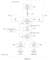
- FIG. 2a is a block diagram representation of the alignment electronics.
- a radio frequency source 20 On the ground, there is a radio frequency source 20 and a length of transmission line 14.
- antennas 22, 24 mounted equal distant to the left and the right of the vehicle centerline.
- the antennas 22, 24 are connected by coaxial cable 26 to an antenna switch 28.
- the antenna switch 28 is controlled by the antenna commutation clock 30 to alternately connect one then the other antenna 22, 24 to a conventional frequency modulation radio receiver 32.
- the commutation signal is a 50% duty cycle square wave.
- the commutating action of the antenna switch 28 has no effect upon the receiver signal.
- the amplitude and the phase of the two antenna input signals 31 are identical and there is no response from the receiver 32.
- the vehicle antennas 22, 24 are no longer symmetrical with respect to the transmission line 14.
- the antenna switching action then introduces signal amplitude and phase perturbations at the commutation rate.
- the signal from the antenna closer to the transmission line 14 will have larger amplitude and leading phase with respect to the more distant antenna.
- the frequency modulation receiver 32 ignores the amplitude perturbations but detects the phase perturbations, frequency being the time rate of change of phase, thereby replicating the antenna switch commutation signal in the receiver audio output 34.
- the receiver audio commutation signal replica is altered by the limited receiver bandwidth. If the commutating signal frequency is above the receiver recovered audio pass band, there is no recovered commutation signal. If the commutating signal frequency is just above the lower receiver audio pass band frequency, the recovered commutation signal will approximate the original commutation square wave albeit low pass filtered by the receiver upper audio pass band limit. A commutation signal frequency in the upper half of the receiver audio pass band leads to a largely sinusoidal recovered audio signal.
- the audio output 34 is provided to synchronous detector 36 to detect the phase differences between the respective antenna signals, and output signals representative of any misalignments are provided to a voltage comparator 38 to determine alignment error polarity based on which signal has a leading phase or lagging phase and to an absolute value detector 40 that determines the alignment error magnitude.
- the alignment error polarity and alignment error magnitude signals are provided to a display device and other audiovisual means to provide feedback to the driver for adjusting the vehicle in the parking slot 10 with respect to the wireless power induction coil 12.
- Figure 2b depicts an example representation of phase differences between the respective alignment antennas as a function of the alignment error or displacement from centerline.
- the system maximum operating frequency provided by radio frequency source 20 is set by the separation between the two vehicle mounted antennas 22, 24 which must be less than the width of the vehicle. In the United States, the average parking slot width is about nine feet. Automobiles are typically no more than 8 feet wide. In order to avoid phase ambiguity, the two sensing antennas 22, 24 must be spaced no more than ⁇ /2 apart at the operating frequency. For two sensing antennas separated by eight feet, the maximum system operating frequency is about 61.5 MHz. Higher frequencies and narrower antenna spacing is possible if the vehicle driver can be assumed to enter the parking slot with an initial alignment error less than 1 ⁇ 2 of the parking slot width. Higher operating frequencies are also possible with the use of more than two vehicle mounted antennas with the additional antenna or antennas used to resolve phase ambiguity. Those skilled in the art will appreciate that there is no lower limit on the system operating frequency except the signal to noise ratio of alignment error becomes progressively worse as the operating frequency is lowered.
- the apparatus described herein provides for vehicle alignment left-right with respect to the parking slot centerline.
- Vehicle left-right misalignment is indicated to the driver by visible, audible or tactile means.
- a visual indication can be an illuminated indicator, a graphical display or software generated graphical overlay imposed upon a video camera image.
- An audible indication may be a continuous or pulsating sound or a software generated speech synthesizer.
- Tactile indication can be provided by the vehicle steering wheel or steering mechanism, gear shift lever, the driver's seat or through the vehicle floor or through floor mounted vehicle control pedals.
- Driver visual cues or technical means described, for example, in U.S. Provisional Patent Application No. 61/862,572, filed August 6, 2013 may be used to indicate and control where the aligned vehicle should stop for axial coil alignment in the front-back directions for assurance that the driver pulls far enough into the parking slot 10 to align the magnetic coils for charging.
- Figures 3a and 3b illustrate sample embodiments of the transmission line 14.
- Figure 3a shows the radio frequency source 20 and a buried or surface mounted transmission line 14 that leaks a signal at the operating frequency.
- a 40.68 MHz, fiftyohm impedance continuous wave radio frequency source 20 provides radio frequency excitation.
- a power level of about 1 mW is used.
- a mini-circuits RF transformer 42, model number ADT 4-6'1' is used as an impedance matching balun.
- the transmission line 14 is implemented with a length of ordinary 300-ohm characteristic impedance balance transmission line. While this transmission line is not designed to be leaky, there is sufficient leakage to be picked up by antennas 22, 24 in sample embodiments.
- a 300-ohm resistor 44 terminates the end of the balance line in order to eliminate reflections and standing waves.
- the transmission line does not have to be balanced; a leaky un-balanced coaxial line would be equally suitable.
- other transmission line impedances such as 50 or 75-ohm coaxial cable with slots in the outer shielding could equally be used.
- Figure 3b depicts an unbalanced 50 or 75 Ohm coaxial cable transmission line 14' with specially designed slots 43 and termination resistor 45 that is matched to the coaxial cable's characteristic impedance.
- FIG 4 shows the circuitry associated with the antennas 22, 24, antenna commutating switch 28, and commutation clock 30 of Figure 2 .
- the antennas 22, 24 include rectangular spirals fabricated on a printed circuit board to ensure antenna-to-antenna consistency. The number of turns for the rectangular spirals depends on the desired value of inductance for the antenna that will be resonated with capacitance to achieve the desired response at the operating frequency. In a sample configuration, ten turn rectangular spirals were used for antennas 22, 24.
- the antennas 22, 24 are electrically small and are not resonant at the operating frequency without the employment of an additional capacitance.
- Each antenna 22, 24 is connected to a length of ordinary 50-ohm characteristic impedance coaxial cable 26.
- the two cables 26 are equal in length when the antennas are symmetrically spaced with respect to the centerline of the vehicle and each has a ferrite sleeve 46 including several ferrite beads slipped over the cable 26 at the ends connected to the antennas 22, 24 to serve as baluns and to suppress RF currents that would otherwise be induced on the cable outer conductors. Induced RF currents introduce significant system errors and must be suppressed.
- An operation frequency of 40.68 MHz is used in a sample embodiment. This frequency is near optimum for this application and is allocated nationally and internationally for ISM (Industrial, Scientific and Medical) uses which include RF heating, Doppler based frequency or phase sensitive motion and intrusion alarms, diathermy, cauterization and other non-communications uses.
- ISM frequencies are set aside for non-communications uses, but they can also be used for communications if the users are willing to accept the possibility of radio interference from the primary ISM applications.
- the advantage for doing so is significantly reduced equipment certification and spectrum allocation regulatory burdens.
- the maximum range of the vehicle alignment system described herein is a few feet at most, the probability of radio interference from other 40.68 MHz ISM frequency users is quite remote.
- An RC oscillator 30 comprised of two logic inverters 4-8, resistors R6 and R7 along with capacitor C6 generates a rectangular wave signal at twice the desired antenna commutation frequency which is then divided by 2 by a D flip-flop 50, thereby generating a commutation clock at the desired frequency with 50-50 duty cycle.
- Components R1, R3, R4, DI, D2, and LI comprise a diode RF switch 28 controlled by the Q and not Q flip-flop outputs.
- R2, R5, C4, and C5 slow the leading and trailing edges of the switch control waveform thereby limiting switching transients.
- R8, C8 and associated logic inverters 52 delay the antenna commutation clock control signal to compensate for the receiver delay.
- FIG. 5 shows the post receiver signal processing circuitry.
- the output of the antenna commutation switch 28 goes to the antenna input of a conventional narrowband FM receiver 32.
- the circuit includes a consumer grade pocket sized scanning receiver, a Uniden BC72XLY compact scanner, but any narrowband VHF FM receiver implementation, analog or digital, hardware or software is acceptable.
- Vehicle alignment error appears in the receiver audio output as a bandwidth limited square wave at the antenna commutation clock frequency. Square wave magnitude indicates alignment error magnitude; square wave polarity indicates alignment error direction, left or right. Synchronous detection then produces a DC voltage with amplitude proportional to alignment error and with polarity indicating alignment error direction.
- the two op-amps 54 amplify the audio signal from the FM receiver by gains of one and minus one.
- Integrated circuit 56 contains three single-pole double throw (SPDT) CMOS FET switches one of which is used as a synchronous rectifier driven by the delayed antenna commutation switch control signal.
- a low pass filter 58 comprised of resistor R16 and capacitor Cl I follows the SPDT switch 56 removing all commutation frequency ripples leaving a direct current signal with amplitude proportional to vehicle misalignment and polarity determined by the direction of the vehicle alignment error, left or right of the parking slot centerline.
- An absolute magnitude circuit recovers the magnitude of the vehicle displacement error while a voltage comparator determines the error polarity.
- the two op-amps 60, 62 are used as a post RC low pass filter buffer amplifier and as a zero-reference voltage comparator, respectively.
- the components associated with transistor 64 keep the op-amp section out of voltage saturation thereby avoiding the subtle problems sometimes experienced when using op-amps in an open-loop connection as voltage comparators.
- the voltage comparator 38 implemented by op-amp 62, provides a logic level signal that indicates the polarity of the alignment error, left or right.
- Op-amps 66 and associated components comprise an absolute value detector 40 providing a unipolar representation of the alignment error magnitude independent of the polarity of the post synchronous detector signal.
- the vehicle dual sense antennas 22, 24 and the transmission line 14 are mounted along the vehicle centerline and parking slot center line, respectively. Offset locations as might be required to avoid vehicle underbody and parking slot obstacles can be accommodated by including the appropriate offset correction in the post synchronous detector hardware or software. In the latter situation, the required offset correction is provided by the ground to vehicle communications link.
Landscapes
- Engineering & Computer Science (AREA)
- Power Engineering (AREA)
- Transportation (AREA)
- Mechanical Engineering (AREA)
- Computer Networks & Wireless Communication (AREA)
- Electric Propulsion And Braking For Vehicles (AREA)
- Near-Field Transmission Systems (AREA)
- Charge And Discharge Circuits For Batteries Or The Like (AREA)
- Current-Collector Devices For Electrically Propelled Vehicles (AREA)
Applications Claiming Priority (2)
| Application Number | Priority Date | Filing Date | Title |
|---|---|---|---|
| US16/030,036 US10814729B2 (en) | 2013-11-14 | 2018-07-09 | Method and apparatus for the alignment of a vehicle and charging coil prior to wireless charging |
| PCT/US2019/039161 WO2020013989A1 (en) | 2018-07-09 | 2019-06-26 | Alignment of vehicles prior to wireless charging |
Publications (3)
| Publication Number | Publication Date |
|---|---|
| EP3821519A1 EP3821519A1 (en) | 2021-05-19 |
| EP3821519A4 EP3821519A4 (en) | 2021-09-01 |
| EP3821519B1 true EP3821519B1 (en) | 2023-08-16 |
Family
ID=69141900
Family Applications (1)
| Application Number | Title | Priority Date | Filing Date |
|---|---|---|---|
| EP19834203.2A Active EP3821519B1 (en) | 2018-07-09 | 2019-06-26 | Alignment of vehicles prior to wireless charging |
Country Status (8)
| Country | Link |
|---|---|
| EP (1) | EP3821519B1 (https=) |
| JP (1) | JP7281832B2 (https=) |
| KR (1) | KR102746818B1 (https=) |
| CN (1) | CN112425031A (https=) |
| ES (1) | ES2955420T3 (https=) |
| MX (1) | MX2021000249A (https=) |
| PT (1) | PT3821519T (https=) |
| WO (1) | WO2020013989A1 (https=) |
Families Citing this family (5)
| Publication number | Priority date | Publication date | Assignee | Title |
|---|---|---|---|---|
| US11241970B2 (en) | 2013-11-14 | 2022-02-08 | Momentum Dynamics Corporation | Method and apparatus for the alignment of vehicles prior to wireless charging |
| US10814729B2 (en) | 2013-11-14 | 2020-10-27 | Momentum Dynamics Corporation | Method and apparatus for the alignment of a vehicle and charging coil prior to wireless charging |
| CN110435645B (zh) * | 2019-08-28 | 2021-11-26 | 江西江铃集团新能源汽车有限公司 | 自动泊车控制方法、装置、系统及可读存储介质 |
| WO2023129307A1 (en) * | 2022-01-03 | 2023-07-06 | InductEV, Inc. | Method and apparatus for the selective guidance of vehicles to a wireless charger |
| US12145461B2 (en) | 2022-01-06 | 2024-11-19 | Ev Charging Solutions, Llc | Inductive charging station |
Family Cites Families (31)
| Publication number | Priority date | Publication date | Assignee | Title |
|---|---|---|---|---|
| US4219821A (en) * | 1978-09-07 | 1980-08-26 | Regency Electronics, Inc. | Automatic direction finding system |
| JPS63115207A (ja) * | 1986-10-31 | 1988-05-19 | Murata Mach Ltd | 無人車の走行誘導装置 |
| JPH10103965A (ja) * | 1996-09-27 | 1998-04-24 | Fujitsu Ten Ltd | 電波反射体に対する車両の変位量検出方法 |
| JP3520765B2 (ja) * | 1998-04-28 | 2004-04-19 | 株式会社デンソー | 車両案内用タグを用いた車線変更管理システム |
| JP2001005523A (ja) * | 1999-06-22 | 2001-01-12 | Uchihashi Estec Co Ltd | 自動駐車方法 |
| JP2007010639A (ja) | 2004-08-16 | 2007-01-18 | Rcs:Kk | アクティブタグ装置 |
| JP2006072431A (ja) * | 2004-08-31 | 2006-03-16 | Matsushita Electric Ind Co Ltd | 自動駐車システム |
| CN101371541A (zh) | 2006-01-11 | 2009-02-18 | 鲍尔卡斯特公司 | 脉冲传输方法 |
| CN1891966B (zh) * | 2006-02-28 | 2012-06-27 | 谢明宗 | 无轨门驱动导向装置 |
| JP2010246348A (ja) | 2009-04-09 | 2010-10-28 | Fujitsu Ten Ltd | 受電装置、及び送電装置 |
| WO2012018268A1 (en) * | 2010-08-05 | 2012-02-09 | Auckland Uniservices Limited | Inductive power transfer apparatus |
| US8513915B2 (en) * | 2010-10-21 | 2013-08-20 | GM Global Technology Operations LLC | Vehicle alignment for inductive charging |
| US10090885B2 (en) * | 2011-04-13 | 2018-10-02 | Qualcomm Incorporated | Antenna alignment and vehicle guidance for wireless charging of electric vehicles |
| US9637014B2 (en) * | 2011-06-28 | 2017-05-02 | Wireless Ev Charge, Llc | Alignment, verification, and optimization of high power wireless charging systems |
| CN202711064U (zh) * | 2012-01-09 | 2013-01-30 | 谢朝京 | 一种agv小车引导传感装置 |
| CN102819265A (zh) * | 2012-08-29 | 2012-12-12 | 上海富洋自动化工程设备有限公司 | 连续绝对地址系统的运载式机器人自动车 |
| US9409490B2 (en) | 2013-09-27 | 2016-08-09 | Qualcomm Incorporated | Device alignment in inductive power transfer systems |
| DE102013227129B4 (de) * | 2013-12-23 | 2016-01-14 | Continental Automotive Gmbh | Verfahren zur Erfassung einer Relativposition, Verfahren zum kabellosen Laden eines Fahrzeugs, Orientierungssignalempfänger und induktive Ladevorrichtung |
| US9772401B2 (en) * | 2014-03-17 | 2017-09-26 | Qualcomm Incorporated | Systems, methods, and apparatus for radar-based detection of objects in a predetermined space |
| US10317526B2 (en) * | 2014-09-25 | 2019-06-11 | Continental Teves Ag & Co. Ohg | Localization of charging coils, which is integrated in distance sensors |
| US10411524B2 (en) | 2015-06-23 | 2019-09-10 | Witricity Corporation | Systems, methods and apparatuses for guidance and alignment in electric vehicles wireless inductive charging systems |
| CN204808055U (zh) * | 2015-07-22 | 2015-11-25 | 厦门新页科技有限公司 | 一种电动汽车无线充电发射接收自动对准系统 |
| KR101803151B1 (ko) * | 2015-10-16 | 2017-11-29 | 현대자동차주식회사 | 무선 충전 시스템의 자기장 정렬 방법 및 장치와 이에 이용되는 일차 패드 |
| US10336194B2 (en) * | 2015-11-13 | 2019-07-02 | Nio Usa, Inc. | Electric vehicle charging device alignment and method of use |
| CN205264050U (zh) * | 2015-12-24 | 2016-05-25 | 上海展为软件技术有限公司 | 一种基于地磁引导的微波车辆检测装置 |
| US9837706B2 (en) * | 2016-02-19 | 2017-12-05 | Ford Global Technologies, Llc | Directing electromagnetic waves in vehicle communications |
| US10011182B2 (en) * | 2016-03-24 | 2018-07-03 | Ford Global Technologies, Llc | Inductive charger alignment systems for vehicles |
| US10369894B2 (en) * | 2016-10-21 | 2019-08-06 | Hevo, Inc. | Parking alignment sequence for wirelessly charging an electric vehicle |
| CN106981215B (zh) * | 2017-03-23 | 2020-09-11 | 北京联合大学 | 一种多传感器组合式的自动泊车车位引导方法 |
| CN206851844U (zh) * | 2017-05-04 | 2018-01-09 | 曲靖师范学院 | 一种远程智能控制农药喷洒车 |
| CN107757397A (zh) * | 2017-09-19 | 2018-03-06 | 深圳大学 | 一种修正车辆无线充电对位误差的控制装置及方法 |
-
2019
- 2019-06-26 WO PCT/US2019/039161 patent/WO2020013989A1/en not_active Ceased
- 2019-06-26 PT PT198342032T patent/PT3821519T/pt unknown
- 2019-06-26 ES ES19834203T patent/ES2955420T3/es active Active
- 2019-06-26 KR KR1020217003717A patent/KR102746818B1/ko active Active
- 2019-06-26 EP EP19834203.2A patent/EP3821519B1/en active Active
- 2019-06-26 JP JP2021500391A patent/JP7281832B2/ja active Active
- 2019-06-26 MX MX2021000249A patent/MX2021000249A/es unknown
- 2019-06-26 CN CN201980046097.0A patent/CN112425031A/zh active Pending
Also Published As
| Publication number | Publication date |
|---|---|
| ES2955420T3 (es) | 2023-11-30 |
| PT3821519T (pt) | 2023-09-05 |
| EP3821519A1 (en) | 2021-05-19 |
| JP2021530950A (ja) | 2021-11-11 |
| CN112425031A (zh) | 2021-02-26 |
| EP3821519A4 (en) | 2021-09-01 |
| CA3105049A1 (en) | 2020-01-16 |
| WO2020013989A1 (en) | 2020-01-16 |
| KR102746818B1 (ko) | 2024-12-27 |
| JP7281832B2 (ja) | 2023-05-26 |
| KR20210029797A (ko) | 2021-03-16 |
| MX2021000249A (es) | 2021-05-12 |
Similar Documents
| Publication | Publication Date | Title |
|---|---|---|
| US10814729B2 (en) | Method and apparatus for the alignment of a vehicle and charging coil prior to wireless charging | |
| US11241970B2 (en) | Method and apparatus for the alignment of vehicles prior to wireless charging | |
| EP3821519B1 (en) | Alignment of vehicles prior to wireless charging | |
| US10040360B1 (en) | Method and apparatus for the alignment of vehicles prior to wireless charging including a transmission line that leaks a signal for alignment | |
| US10404107B2 (en) | Non-contact charging device, and non-contact power supply system using same | |
| EP2961036B1 (en) | Foreign object detection device, foreign object detection method, and non-contact charging system | |
| EP3031128B1 (en) | A method of and apparatus for detecting coil alignment error in wireless inductive power transmission | |
| EP3347230B1 (en) | A system and a method for determining a relative position and/or orientation between a primary and a secondary winding structure | |
| US9812254B2 (en) | Wireless power feeder | |
| KR20150038050A (ko) | 유도성 전력 전달 시스템들에서의 디바이스 정렬 및 식별 | |
| CA3163907C (en) | METHOD AND DEVICE FOR ALIGNING VEHICLES BEFORE WIRELESS CHARGING | |
| CA3105049C (en) | Alignment of vehicles prior to wireless charging | |
| EP3900152B1 (en) | An antenna arrangement and a method of operating an antenna arrangement | |
| EP1869612B1 (en) | Rfid reader with an antenna and method for operating the same | |
| JP3339421B2 (ja) | 非接触給電システム | |
| CA3247511A1 (en) | INDUCTION ENERGY TRANSFER SYSTEM |
Legal Events
| Date | Code | Title | Description |
|---|---|---|---|
| STAA | Information on the status of an ep patent application or granted ep patent |
Free format text: STATUS: THE INTERNATIONAL PUBLICATION HAS BEEN MADE |
|
| PUAI | Public reference made under article 153(3) epc to a published international application that has entered the european phase |
Free format text: ORIGINAL CODE: 0009012 |
|
| STAA | Information on the status of an ep patent application or granted ep patent |
Free format text: STATUS: REQUEST FOR EXAMINATION WAS MADE |
|
| 17P | Request for examination filed |
Effective date: 20210126 |
|
| AK | Designated contracting states |
Kind code of ref document: A1 Designated state(s): AL AT BE BG CH CY CZ DE DK EE ES FI FR GB GR HR HU IE IS IT LI LT LU LV MC MK MT NL NO PL PT RO RS SE SI SK SM TR |
|
| A4 | Supplementary search report drawn up and despatched |
Effective date: 20210729 |
|
| RIC1 | Information provided on ipc code assigned before grant |
Ipc: H02J 50/90 20160101AFI20210723BHEP Ipc: B60L 53/12 20190101ALI20210723BHEP Ipc: B60L 53/36 20190101ALI20210723BHEP Ipc: B60L 53/38 20190101ALI20210723BHEP |
|
| DAV | Request for validation of the european patent (deleted) | ||
| DAX | Request for extension of the european patent (deleted) | ||
| RAP3 | Party data changed (applicant data changed or rights of an application transferred) |
Owner name: INDUCTEV INC. |
|
| GRAP | Despatch of communication of intention to grant a patent |
Free format text: ORIGINAL CODE: EPIDOSNIGR1 |
|
| STAA | Information on the status of an ep patent application or granted ep patent |
Free format text: STATUS: GRANT OF PATENT IS INTENDED |
|
| INTG | Intention to grant announced |
Effective date: 20230320 |
|
| RAP3 | Party data changed (applicant data changed or rights of an application transferred) |
Owner name: INDUCTEV INC. |
|
| GRAS | Grant fee paid |
Free format text: ORIGINAL CODE: EPIDOSNIGR3 |
|
| GRAA | (expected) grant |
Free format text: ORIGINAL CODE: 0009210 |
|
| STAA | Information on the status of an ep patent application or granted ep patent |
Free format text: STATUS: THE PATENT HAS BEEN GRANTED |
|
| AK | Designated contracting states |
Kind code of ref document: B1 Designated state(s): AL AT BE BG CH CY CZ DE DK EE ES FI FR GB GR HR HU IE IS IT LI LT LU LV MC MK MT NL NO PL PT RO RS SE SI SK SM TR |
|
| REG | Reference to a national code |
Ref country code: CH Ref legal event code: EP |
|
| REG | Reference to a national code |
Ref country code: PT Ref legal event code: SC4A Ref document number: 3821519 Country of ref document: PT Date of ref document: 20230905 Kind code of ref document: T Free format text: AVAILABILITY OF NATIONAL TRANSLATION Effective date: 20230828 |
|
| REG | Reference to a national code |
Ref country code: DE Ref legal event code: R096 Ref document number: 602019035271 Country of ref document: DE |
|
| REG | Reference to a national code |
Ref country code: IE Ref legal event code: FG4D |
|
| REG | Reference to a national code |
Ref country code: SE Ref legal event code: TRGR |
|
| REG | Reference to a national code |
Ref country code: ES Ref legal event code: FG2A Ref document number: 2955420 Country of ref document: ES Kind code of ref document: T3 Effective date: 20231130 |
|
| REG | Reference to a national code |
Ref country code: LT Ref legal event code: MG9D |
|
| REG | Reference to a national code |
Ref country code: NL Ref legal event code: MP Effective date: 20230816 |
|
| PG25 | Lapsed in a contracting state [announced via postgrant information from national office to epo] |
Ref country code: GR Free format text: LAPSE BECAUSE OF FAILURE TO SUBMIT A TRANSLATION OF THE DESCRIPTION OR TO PAY THE FEE WITHIN THE PRESCRIBED TIME-LIMIT Effective date: 20231117 |
|
| PG25 | Lapsed in a contracting state [announced via postgrant information from national office to epo] |
Ref country code: IS Free format text: LAPSE BECAUSE OF FAILURE TO SUBMIT A TRANSLATION OF THE DESCRIPTION OR TO PAY THE FEE WITHIN THE PRESCRIBED TIME-LIMIT Effective date: 20231216 |
|
| PG25 | Lapsed in a contracting state [announced via postgrant information from national office to epo] |
Ref country code: RS Free format text: LAPSE BECAUSE OF FAILURE TO SUBMIT A TRANSLATION OF THE DESCRIPTION OR TO PAY THE FEE WITHIN THE PRESCRIBED TIME-LIMIT Effective date: 20230816 Ref country code: NO Free format text: LAPSE BECAUSE OF FAILURE TO SUBMIT A TRANSLATION OF THE DESCRIPTION OR TO PAY THE FEE WITHIN THE PRESCRIBED TIME-LIMIT Effective date: 20231116 Ref country code: NL Free format text: LAPSE BECAUSE OF FAILURE TO SUBMIT A TRANSLATION OF THE DESCRIPTION OR TO PAY THE FEE WITHIN THE PRESCRIBED TIME-LIMIT Effective date: 20230816 Ref country code: LV Free format text: LAPSE BECAUSE OF FAILURE TO SUBMIT A TRANSLATION OF THE DESCRIPTION OR TO PAY THE FEE WITHIN THE PRESCRIBED TIME-LIMIT Effective date: 20230816 Ref country code: LT Free format text: LAPSE BECAUSE OF FAILURE TO SUBMIT A TRANSLATION OF THE DESCRIPTION OR TO PAY THE FEE WITHIN THE PRESCRIBED TIME-LIMIT Effective date: 20230816 Ref country code: IS Free format text: LAPSE BECAUSE OF FAILURE TO SUBMIT A TRANSLATION OF THE DESCRIPTION OR TO PAY THE FEE WITHIN THE PRESCRIBED TIME-LIMIT Effective date: 20231216 Ref country code: HR Free format text: LAPSE BECAUSE OF FAILURE TO SUBMIT A TRANSLATION OF THE DESCRIPTION OR TO PAY THE FEE WITHIN THE PRESCRIBED TIME-LIMIT Effective date: 20230816 Ref country code: GR Free format text: LAPSE BECAUSE OF FAILURE TO SUBMIT A TRANSLATION OF THE DESCRIPTION OR TO PAY THE FEE WITHIN THE PRESCRIBED TIME-LIMIT Effective date: 20231117 Ref country code: FI Free format text: LAPSE BECAUSE OF FAILURE TO SUBMIT A TRANSLATION OF THE DESCRIPTION OR TO PAY THE FEE WITHIN THE PRESCRIBED TIME-LIMIT Effective date: 20230816 |
|
| PG25 | Lapsed in a contracting state [announced via postgrant information from national office to epo] |
Ref country code: PL Free format text: LAPSE BECAUSE OF FAILURE TO SUBMIT A TRANSLATION OF THE DESCRIPTION OR TO PAY THE FEE WITHIN THE PRESCRIBED TIME-LIMIT Effective date: 20230816 |
|
| PG25 | Lapsed in a contracting state [announced via postgrant information from national office to epo] |
Ref country code: SM Free format text: LAPSE BECAUSE OF FAILURE TO SUBMIT A TRANSLATION OF THE DESCRIPTION OR TO PAY THE FEE WITHIN THE PRESCRIBED TIME-LIMIT Effective date: 20230816 Ref country code: RO Free format text: LAPSE BECAUSE OF FAILURE TO SUBMIT A TRANSLATION OF THE DESCRIPTION OR TO PAY THE FEE WITHIN THE PRESCRIBED TIME-LIMIT Effective date: 20230816 Ref country code: EE Free format text: LAPSE BECAUSE OF FAILURE TO SUBMIT A TRANSLATION OF THE DESCRIPTION OR TO PAY THE FEE WITHIN THE PRESCRIBED TIME-LIMIT Effective date: 20230816 Ref country code: DK Free format text: LAPSE BECAUSE OF FAILURE TO SUBMIT A TRANSLATION OF THE DESCRIPTION OR TO PAY THE FEE WITHIN THE PRESCRIBED TIME-LIMIT Effective date: 20230816 Ref country code: CZ Free format text: LAPSE BECAUSE OF FAILURE TO SUBMIT A TRANSLATION OF THE DESCRIPTION OR TO PAY THE FEE WITHIN THE PRESCRIBED TIME-LIMIT Effective date: 20230816 Ref country code: SK Free format text: LAPSE BECAUSE OF FAILURE TO SUBMIT A TRANSLATION OF THE DESCRIPTION OR TO PAY THE FEE WITHIN THE PRESCRIBED TIME-LIMIT Effective date: 20230816 |
|
| REG | Reference to a national code |
Ref country code: DE Ref legal event code: R097 Ref document number: 602019035271 Country of ref document: DE |
|
| PLBE | No opposition filed within time limit |
Free format text: ORIGINAL CODE: 0009261 |
|
| STAA | Information on the status of an ep patent application or granted ep patent |
Free format text: STATUS: NO OPPOSITION FILED WITHIN TIME LIMIT |
|
| 26N | No opposition filed |
Effective date: 20240517 |
|
| PG25 | Lapsed in a contracting state [announced via postgrant information from national office to epo] |
Ref country code: SI Free format text: LAPSE BECAUSE OF FAILURE TO SUBMIT A TRANSLATION OF THE DESCRIPTION OR TO PAY THE FEE WITHIN THE PRESCRIBED TIME-LIMIT Effective date: 20230816 |
|
| PG25 | Lapsed in a contracting state [announced via postgrant information from national office to epo] |
Ref country code: BG Free format text: LAPSE BECAUSE OF FAILURE TO SUBMIT A TRANSLATION OF THE DESCRIPTION OR TO PAY THE FEE WITHIN THE PRESCRIBED TIME-LIMIT Effective date: 20230816 |
|
| PG25 | Lapsed in a contracting state [announced via postgrant information from national office to epo] |
Ref country code: BG Free format text: LAPSE BECAUSE OF FAILURE TO SUBMIT A TRANSLATION OF THE DESCRIPTION OR TO PAY THE FEE WITHIN THE PRESCRIBED TIME-LIMIT Effective date: 20230816 |
|
| PG25 | Lapsed in a contracting state [announced via postgrant information from national office to epo] |
Ref country code: MC Free format text: LAPSE BECAUSE OF FAILURE TO SUBMIT A TRANSLATION OF THE DESCRIPTION OR TO PAY THE FEE WITHIN THE PRESCRIBED TIME-LIMIT Effective date: 20230816 |
|
| REG | Reference to a national code |
Ref country code: CH Ref legal event code: PL |
|
| PG25 | Lapsed in a contracting state [announced via postgrant information from national office to epo] |
Ref country code: LU Free format text: LAPSE BECAUSE OF NON-PAYMENT OF DUE FEES Effective date: 20240626 |
|
| PGFP | Annual fee paid to national office [announced via postgrant information from national office to epo] |
Ref country code: SE Payment date: 20250313 Year of fee payment: 7 |
|
| PG25 | Lapsed in a contracting state [announced via postgrant information from national office to epo] |
Ref country code: IE Free format text: LAPSE BECAUSE OF NON-PAYMENT OF DUE FEES Effective date: 20240626 |
|
| PG25 | Lapsed in a contracting state [announced via postgrant information from national office to epo] |
Ref country code: BE Free format text: LAPSE BECAUSE OF NON-PAYMENT OF DUE FEES Effective date: 20240630 Ref country code: CH Free format text: LAPSE BECAUSE OF NON-PAYMENT OF DUE FEES Effective date: 20240630 |
|
| REG | Reference to a national code |
Ref country code: BE Ref legal event code: MM Effective date: 20240630 |
|
| PGFP | Annual fee paid to national office [announced via postgrant information from national office to epo] |
Ref country code: DE Payment date: 20250513 Year of fee payment: 7 |
|
| PGFP | Annual fee paid to national office [announced via postgrant information from national office to epo] |
Ref country code: GB Payment date: 20250513 Year of fee payment: 7 |
|
| PGFP | Annual fee paid to national office [announced via postgrant information from national office to epo] |
Ref country code: IT Payment date: 20250409 Year of fee payment: 7 |
|
| PGFP | Annual fee paid to national office [announced via postgrant information from national office to epo] |
Ref country code: PT Payment date: 20250408 Year of fee payment: 7 |
|
| PGFP | Annual fee paid to national office [announced via postgrant information from national office to epo] |
Ref country code: FR Payment date: 20250509 Year of fee payment: 7 |
|
| PGFP | Annual fee paid to national office [announced via postgrant information from national office to epo] |
Ref country code: AT Payment date: 20250512 Year of fee payment: 7 |
|
| PGFP | Annual fee paid to national office [announced via postgrant information from national office to epo] |
Ref country code: ES Payment date: 20250708 Year of fee payment: 7 |
|
| PG25 | Lapsed in a contracting state [announced via postgrant information from national office to epo] |
Ref country code: CY Free format text: LAPSE BECAUSE OF FAILURE TO SUBMIT A TRANSLATION OF THE DESCRIPTION OR TO PAY THE FEE WITHIN THE PRESCRIBED TIME-LIMIT; INVALID AB INITIO Effective date: 20190626 |
|
| PG25 | Lapsed in a contracting state [announced via postgrant information from national office to epo] |
Ref country code: HU Free format text: LAPSE BECAUSE OF FAILURE TO SUBMIT A TRANSLATION OF THE DESCRIPTION OR TO PAY THE FEE WITHIN THE PRESCRIBED TIME-LIMIT; INVALID AB INITIO Effective date: 20190626 |