EP3819989B1 - Elektrisch leitende verbindung von leiterplatten - Google Patents
Elektrisch leitende verbindung von leiterplatten Download PDFInfo
- Publication number
- EP3819989B1 EP3819989B1 EP20203596.0A EP20203596A EP3819989B1 EP 3819989 B1 EP3819989 B1 EP 3819989B1 EP 20203596 A EP20203596 A EP 20203596A EP 3819989 B1 EP3819989 B1 EP 3819989B1
- Authority
- EP
- European Patent Office
- Prior art keywords
- circuit board
- opening
- connection
- electrically conductive
- section
- Prior art date
- Legal status (The legal status is an assumption and is not a legal conclusion. Google has not performed a legal analysis and makes no representation as to the accuracy of the status listed.)
- Active
Links
Images


Classifications
-
- H—ELECTRICITY
- H01—ELECTRIC ELEMENTS
- H01R—ELECTRICALLY-CONDUCTIVE CONNECTIONS; STRUCTURAL ASSOCIATIONS OF A PLURALITY OF MUTUALLY-INSULATED ELECTRICAL CONNECTING ELEMENTS; COUPLING DEVICES; CURRENT COLLECTORS
- H01R12/00—Structural associations of a plurality of mutually-insulated electrical connecting elements, specially adapted for printed circuits, e.g. printed circuit boards [PCB], flat or ribbon cables, or like generally planar structures, e.g. terminal strips, terminal blocks; Coupling devices specially adapted for printed circuits, flat or ribbon cables, or like generally planar structures; Terminals specially adapted for contact with, or insertion into, printed circuits, flat or ribbon cables, or like generally planar structures
- H01R12/50—Fixed connections
- H01R12/51—Fixed connections for rigid printed circuits or like structures
- H01R12/52—Fixed connections for rigid printed circuits or like structures connecting to other rigid printed circuits or like structures
- H01R12/523—Fixed connections for rigid printed circuits or like structures connecting to other rigid printed circuits or like structures by an interconnection through aligned holes in the boards or multilayer board
-
- H—ELECTRICITY
- H01—ELECTRIC ELEMENTS
- H01R—ELECTRICALLY-CONDUCTIVE CONNECTIONS; STRUCTURAL ASSOCIATIONS OF A PLURALITY OF MUTUALLY-INSULATED ELECTRICAL CONNECTING ELEMENTS; COUPLING DEVICES; CURRENT COLLECTORS
- H01R12/00—Structural associations of a plurality of mutually-insulated electrical connecting elements, specially adapted for printed circuits, e.g. printed circuit boards [PCB], flat or ribbon cables, or like generally planar structures, e.g. terminal strips, terminal blocks; Coupling devices specially adapted for printed circuits, flat or ribbon cables, or like generally planar structures; Terminals specially adapted for contact with, or insertion into, printed circuits, flat or ribbon cables, or like generally planar structures
- H01R12/50—Fixed connections
- H01R12/51—Fixed connections for rigid printed circuits or like structures
- H01R12/55—Fixed connections for rigid printed circuits or like structures characterised by the terminals
- H01R12/58—Fixed connections for rigid printed circuits or like structures characterised by the terminals terminals for insertion into holes
- H01R12/585—Terminals having a press fit or a compliant portion and a shank passing through a hole in the printed circuit board
-
- H—ELECTRICITY
- H01—ELECTRIC ELEMENTS
- H01R—ELECTRICALLY-CONDUCTIVE CONNECTIONS; STRUCTURAL ASSOCIATIONS OF A PLURALITY OF MUTUALLY-INSULATED ELECTRICAL CONNECTING ELEMENTS; COUPLING DEVICES; CURRENT COLLECTORS
- H01R12/00—Structural associations of a plurality of mutually-insulated electrical connecting elements, specially adapted for printed circuits, e.g. printed circuit boards [PCB], flat or ribbon cables, or like generally planar structures, e.g. terminal strips, terminal blocks; Coupling devices specially adapted for printed circuits, flat or ribbon cables, or like generally planar structures; Terminals specially adapted for contact with, or insertion into, printed circuits, flat or ribbon cables, or like generally planar structures
- H01R12/50—Fixed connections
- H01R12/59—Fixed connections for flexible printed circuits, flat or ribbon cables or like structures
- H01R12/62—Fixed connections for flexible printed circuits, flat or ribbon cables or like structures connecting to rigid printed circuits or like structures
-
- H—ELECTRICITY
- H01—ELECTRIC ELEMENTS
- H01R—ELECTRICALLY-CONDUCTIVE CONNECTIONS; STRUCTURAL ASSOCIATIONS OF A PLURALITY OF MUTUALLY-INSULATED ELECTRICAL CONNECTING ELEMENTS; COUPLING DEVICES; CURRENT COLLECTORS
- H01R12/00—Structural associations of a plurality of mutually-insulated electrical connecting elements, specially adapted for printed circuits, e.g. printed circuit boards [PCB], flat or ribbon cables, or like generally planar structures, e.g. terminal strips, terminal blocks; Coupling devices specially adapted for printed circuits, flat or ribbon cables, or like generally planar structures; Terminals specially adapted for contact with, or insertion into, printed circuits, flat or ribbon cables, or like generally planar structures
- H01R12/50—Fixed connections
- H01R12/59—Fixed connections for flexible printed circuits, flat or ribbon cables or like structures
- H01R12/65—Fixed connections for flexible printed circuits, flat or ribbon cables or like structures characterised by the terminal
- H01R12/69—Fixed connections for flexible printed circuits, flat or ribbon cables or like structures characterised by the terminal deformable terminals, e.g. crimping terminals
-
- H—ELECTRICITY
- H01—ELECTRIC ELEMENTS
- H01R—ELECTRICALLY-CONDUCTIVE CONNECTIONS; STRUCTURAL ASSOCIATIONS OF A PLURALITY OF MUTUALLY-INSULATED ELECTRICAL CONNECTING ELEMENTS; COUPLING DEVICES; CURRENT COLLECTORS
- H01R43/00—Apparatus or processes specially adapted for manufacturing, assembling, maintaining, or repairing of line connectors or current collectors or for joining electric conductors
- H01R43/20—Apparatus or processes specially adapted for manufacturing, assembling, maintaining, or repairing of line connectors or current collectors or for joining electric conductors for assembling or disassembling contact members with insulating base, case or sleeve
- H01R43/205—Apparatus or processes specially adapted for manufacturing, assembling, maintaining, or repairing of line connectors or current collectors or for joining electric conductors for assembling or disassembling contact members with insulating base, case or sleeve with a panel or printed circuit board
-
- H—ELECTRICITY
- H05—ELECTRIC TECHNIQUES NOT OTHERWISE PROVIDED FOR
- H05K—PRINTED CIRCUITS; CASINGS OR CONSTRUCTIONAL DETAILS OF ELECTRIC APPARATUS; MANUFACTURE OF ASSEMBLAGES OF ELECTRICAL COMPONENTS
- H05K3/00—Apparatus or processes for manufacturing printed circuits
- H05K3/36—Assembling printed circuits with other printed circuits
- H05K3/361—Assembling flexible printed circuits with other printed circuits
-
- H—ELECTRICITY
- H05—ELECTRIC TECHNIQUES NOT OTHERWISE PROVIDED FOR
- H05K—PRINTED CIRCUITS; CASINGS OR CONSTRUCTIONAL DETAILS OF ELECTRIC APPARATUS; MANUFACTURE OF ASSEMBLAGES OF ELECTRICAL COMPONENTS
- H05K1/00—Printed circuits
- H05K1/02—Details
- H05K1/14—Structural association of two or more printed circuits
- H05K1/147—Structural association of two or more printed circuits at least one of the printed circuits being bent or folded, e.g. by using a flexible printed circuit
-
- H—ELECTRICITY
- H05—ELECTRIC TECHNIQUES NOT OTHERWISE PROVIDED FOR
- H05K—PRINTED CIRCUITS; CASINGS OR CONSTRUCTIONAL DETAILS OF ELECTRIC APPARATUS; MANUFACTURE OF ASSEMBLAGES OF ELECTRICAL COMPONENTS
- H05K1/00—Printed circuits
- H05K1/02—Details
- H05K1/14—Structural association of two or more printed circuits
- H05K1/148—Arrangements of two or more hingeably connected rigid printed circuit boards, i.e. connected by flexible means
-
- H—ELECTRICITY
- H05—ELECTRIC TECHNIQUES NOT OTHERWISE PROVIDED FOR
- H05K—PRINTED CIRCUITS; CASINGS OR CONSTRUCTIONAL DETAILS OF ELECTRIC APPARATUS; MANUFACTURE OF ASSEMBLAGES OF ELECTRICAL COMPONENTS
- H05K2201/00—Indexing scheme relating to printed circuits covered by H05K1/00
- H05K2201/10—Details of components or other objects attached to or integrated in a printed circuit board
- H05K2201/10227—Other objects, e.g. metallic pieces
- H05K2201/10295—Metallic connector elements partly mounted in a hole of the PCB
- H05K2201/10303—Pin-in-hole mounted pins
-
- H—ELECTRICITY
- H05—ELECTRIC TECHNIQUES NOT OTHERWISE PROVIDED FOR
- H05K—PRINTED CIRCUITS; CASINGS OR CONSTRUCTIONAL DETAILS OF ELECTRIC APPARATUS; MANUFACTURE OF ASSEMBLAGES OF ELECTRICAL COMPONENTS
- H05K2201/00—Indexing scheme relating to printed circuits covered by H05K1/00
- H05K2201/10—Details of components or other objects attached to or integrated in a printed circuit board
- H05K2201/10431—Details of mounted components
- H05K2201/1059—Connections made by press-fit insertion
Definitions
- the invention relates to an electrically conductive contact connection between a first and a second printed circuit board according to the preamble of claim 1.
- the invention relates to a method for producing an electrically conductive contact connection between a first printed circuit board and a second printed circuit board according to the preamble of claim 6.
- the EP 0 664 576 A2 and DE 10 2018 10 557 A1 describe circuit board arrangements in which a fixed distance between rigid circuit boards is specified by connection pins.
- JP H08 213068 A discloses a plug connection between a printed circuit board and a flat electrical connection cable.
- JP H08 213068 A and the DE 10 2014 011704 A1 each disclose a contact connection according to the preamble of claim 1.
- the object of the present invention is to provide an electrically conductive contact connection which is more cost-effective than the prior art and can be produced with less effort, and a method for producing the electrically conductive contact connection.
- the connecting pin comprises a second section which is partially arranged in a second opening formed in the second printed circuit board, wherein the second section of the connecting pin comprises a holding element, and the holding element holds the second printed circuit board on a the side facing away from the first circuit board, in such a way that a positive connection is formed between the first and the second circuit board.
- the contact connection according to the invention can be manufactured without requiring any additional soldering. Compared to a plug connection, the contact connection according to the invention requires little material expenditure.
- the retaining element comprises a resilient element or is designed as a resilient element.
- the resilient element can, for example, be compressed when the second section is inserted into the second opening and then, when a part of the second section protrudes from the second opening on a side facing away from the first circuit board, spring back. This then forms the retaining element, which engages over the second circuit board on the side facing away from the first circuit board in such a way that a positive connection is formed between the first and second circuit boards.
- the retaining element is formed by a plastic forming process.
- the second section of the terminal pin is plastically formed at least in a section projecting through the second opening of the second circuit board and beyond the second circuit board. deformable.
- the holding element is then formed, for example, in a forming process, in particular a bending process or a riveting process, in particular as a rivet head.
- the first section of the terminal pin is solid or flexible. If the first section is solid, it is a non-compressible press-in contact. In this case, the first circuit board is deformed in the region of the first opening. If the first section is flexible, the terminal pin is compressed in the region of the first section upon insertion into the first opening by contact with the first opening, thereby creating a preload.
- an inner wall of the first opening of the first circuit board and/or an inner wall of the second opening of the second circuit board comprises an electrically conductive material.
- the inner wall of the first opening of the first circuit board and/or the inner wall of the second opening of the second circuit board are electrically connected to conductor tracks of the first or second circuit board.
- the connecting pin contacts the inner walls of the first and/or second opening at least partially, preferably over their entire circumference, thereby forming an electrically conductive connection.
- the terminal pin is formed at least partially from an electrically conductive material.
- the terminal pin is made, for example, from metal and/or an alloy and/or partially from plastic in combination with an electrically conductive material.
- first and second openings have different diameters. This may prove particularly advantageous when establishing the electrically conductive contact connection.
- the first section of the connecting pin can be assigned to the first opening, and thus to the first circuit board, and the second section of the connecting pin can be assigned to the second opening, and thus to the second circuit board.
- the first circuit board is a rigid circuit board and the second circuit board is a flexible circuit board.
- the first circuit board comprises, for example, a glass fiber mat impregnated with epoxy resin, also known under the material identifier FR4, as a non-conductive carrier material.
- the second circuit board is, for example, a particularly thin circuit board based on polyimide films.
- Such circuit boards can advantageously be designed in a space-saving manner, in particular by folding or bending in the tightest structures, for example in lighting devices, and/or for connecting two rigid circuit boards, for example in
- Lighting devices Further preferred embodiments relate to a method for producing an electrically conductive contact connection between a first circuit board and a second circuit board by means of a connection pin, wherein the first circuit board has a first opening in the region of the contact connection and the second circuit board has a second opening in the region of the contact connection, wherein a first section of the connection pin is pressed into the first opening of the first circuit board, and then a second section of the connection pin is arranged in the second opening of the second circuit board such that a part of the second section protrudes from the second opening on a side of the second circuit board facing away from the first circuit board and, in a further step, a holding element is formed in the protruding part, which engages over the second circuit board such that a positive connection is formed between the first and second circuit boards.
- the holding element comprises a resilient element or is designed as a resilient element.
- Fig. 1 shows an electrically conductive contact connection according to an embodiment not falling within the scope of the claims in a sectional view, which is designated in its entirety by the reference numeral 10.
- the contact connection 10 connects a first circuit board 12 to a second circuit board 14.
- first circuit board 12 there is a first opening 16 and A second opening 18 is formed in the second circuit board.
- the contact connection 10 further comprises a connecting pin 20.
- the connecting pin 20 can also be referred to as a press-fit pin, for example.
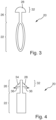
- the connecting pin 20 is shown in a schematic sectional view in Fig. 3
- the terminal pin 20 comprises a first section 22. According to the Figures 1 and 3 In the embodiment shown, the first section 22 is flexible. When inserted into the first opening 18 of the first circuit board 14, the first section 22 is compressed by contact with an inner wall 24 of the first opening 18, thereby creating a prestress and holding the first section 22 in the first opening 16. Thus, a press fit is formed by the section 22 arranged in the first opening 16.
- the connecting pin 20 further comprises a second section 26, which is partially arranged in the second opening 18 of the second circuit board 14 to establish the electrically conductive contact connection 10.
- the second section 26 of the connecting pin 22 comprises a holding element 28.
- the holding element 28 engages over the second circuit board 14 on a side 30 facing away from the first circuit board, such that a positive connection is thereby formed between the first and second circuit boards 12, 14.
- the holding element 28 is in accordance with the Figures 1 and 3 illustrated embodiment is formed by a plastic forming process.
- the second section 26 of the connecting pin 20 is plastically deformable at least in a part 32 protruding through the second opening of the second circuit board and beyond the second circuit board.
- the holding element 28 is then formed, for example, in a forming process, in particular a bending process or a riveting process, in particular as a rivet head.
- the forming takes place under the action of force using a suitable tool.
- the forming comprises, for example, a so-called upsetting of the connecting pin 20 and/or the pre-forming of part 32 of the second section 26 in the form of a rivet head, in particular by circular blows with a ball-head hammer, and/or the final forming of part 32 of the second section 26 in the form of a rivet head, in particular by means of a rivet head setter.
- the holding element 28 is a resilient element 34.
- the resilient element 34 is compressed when the second section 26 is inserted into the second opening 18 in the opposite direction to the arrows 36 and then springs up in the direction of the arrows 36 when the part 32 of the second section 26 protrudes from the second opening 18 on the side 30 facing away from the first circuit board 12. This then forms the holding element 28, which holds the second circuit board 14 on the side facing away from, facing away from the first circuit board, side 30, in such a way that a positive connection is formed between the first and the second circuit board 12, 14.
- first section 22 of the terminal pin 20 is formed according to the Figures 2 and 4
- the first printed circuit board 12 is deformed in the region of the first opening 16 when the first section 22 is inserted into the first opening 16. This is also referred to as a non-compressible press-in contact.
- the connecting pin 20 can also comprise further combinations of the first and second sections 22, 26 (not shown).
- a solid first section 22 can be combined with a deformable second section 26, and a flexible first section 22 can be combined with a second section 26 with a resilient retaining element 32.
- the inner wall 24 of the first opening 16 of the first circuit board 12 and an inner wall 38 of the second opening 18 of the second circuit board 14 comprise an electrically conductive material.
- the terminal pin 20 is formed at least partially from an electrically conductive material.
- the terminal pin 20 is made, for example, from metal and/or an alloy and/or partially from plastic in combination with an electrically conductive material.
- Connection pin 20 contacts the inner walls 24, 38 of the first and/or second opening 16, 18 at least partially, preferably completely, so that an electrically conductive connection is formed between the first circuit board 12 and the second circuit board 14.
Landscapes
- Engineering & Computer Science (AREA)
- Manufacturing & Machinery (AREA)
- Microelectronics & Electronic Packaging (AREA)
- Coupling Device And Connection With Printed Circuit (AREA)
Description
- Die Erfindung betrifft eine elektrisch leitende Kontaktverbindung zwischen einer ersten und einer zweiten Leiterplatte gemäß dem Oberbegriff des Anspruchs 1.
- Ferner betrifft die Erfindung ein Verfahren zum Herstellen einer elektrisch leitenden Kontaktverbindung zwischen einer ersten Leiterplatte und einer zweiten Leiterplatte gemäß dem Oberbegriff des Anspruchs 6.
- Elektrisch leitende Kontaktverbindungen zwischen Bauteilen, beispielsweise Leiterplatten, sind aus dem Stand der Technik bekannt. Aus der
DE 10 2011 119 842 B4 ist ein elektrisches Verbindungselement bekannt, das mehrere aufgelötete Pins umfasst, die in eine Bohrung einer Leiterplatte eingepresst werden können. Gemäß derUS 3,980,367 A werden mehrere Leiterplatten mittels eines von geschmolzenem Lot umgebenen Verbinders miteinander verbunden. - Die
EP 0 664 576 A2 undDE 10 2018 10 557 A1 beschreiben Leiterplattenanordnungen bei denen ein fester Abstand zwischen starren Leiterplatten durch Anschlussstifte vorgegeben wird. - Die
JP H08 213068 A JP H08 213068 A DE 10 2014 011704 A1 offenbaren jeweils eine Kontaktverbindung nach dem Oberbegriff des Anspruchs 1. - Ferner ist es beispielsweise bekannt zwei Leiterplatten, insbesondere einer starre und eine flexible Leiterplatte, über sogenannte Steckverbinderleisten und Leiterplattenbuchsen, Stift- oder Buchsenleisten, die auf den Leiterplatten montiert sind, miteinander zu verbinden. Aufgabe der vorliegenden Erfindung ist es eine gegenüber dem Stand der Technik kostengünstigere, mit einem geringeren Aufwand herstellbare, elektrisch leitende Kontaktverbindung und ein Verfahren zum Herstellen der elektrisch leitenden Kontaktverbindung anzugeben. Erfindungsgemäß wird vorgeschlagen, dass der Anschlussstift einen zweiten Abschnitt umfasst, der teilweise in einer, in der zweiten Leiterplatte ausgebildeten, zweiten Öffnung angeordnet ist, wobei der zweite Abschnitt des Anschlussstifts ein Halteelement umfasst, und das Halteelement die zweite Leiterplatte auf einer von der ersten Leiterplatte abgewandten Seite, derart übergreift, dass zwischen der ersten und der zweiten Leiterplatte eine formschlüssige Verbindung ausgebildet ist.
- Die erfindungsgemäße Kontaktverbindung ist, ohne einen weiteren Lötvorgang zu erfordern, herstellbar. Im Vergleich zu einer Steckverbindung erfordert die erfindungsgemäße Kontaktverbindung wenig Materialaufwand.
- Gemäß der Erfindung ist vorgesehen, dass das Halteelement ein federndes Element umfasst oder als ein federndes Element ausgebildet ist. Das federnde Element kann beispielsweise beim Einführen des zweiten Abschnitts in die zweite Öffnung zusammengedrückt werden, und, anschließend, wenn ein Teil des zweiten Abschnitts auf einer, von der ersten Leiterplatte abgewandten, Seite aus der zweiten Öffnung herausragt, auffedern. Dadurch wird dann das Halteelement ausgebildet, das die zweite Leiterplatte auf der von, der ersten Leiterplatte abgewandten, Seite, derart übergreift, dass dadurch zwischen der ersten und der zweiten Leiterplatte eine formschlüssige Verbindung ausgebildet ist.
- Gemäß einer nicht unter den Schutzumfang der Ansprüche fallenden Ausführungsform kann es sich als vorteilhaft erweisen, wenn das Halteelement durch einen plastischen Umformvorgang ausgebildet ist. Der zweite Abschnitt des Anschlussstifts ist wenigstens in einem durch die zweite Öffnung der zweiten Leiterplatte, über die zweite Leiterplatte herausragenden, Abschnitt plastisch verformbar. Das Halteelement ist dann beispielsweise in einem Umformvorgang, insbesondere einem Biegevorgang oder einem Nietvorgang, insbesondere als ein Nietkopf, ausgebildet.
- Es kann sich weiter als vorteilhaft erweisen, wenn der erste Abschnitt des Anschlussstifts massiv oder flexibel ausgebildet ist. Wenn der erste Abschnitt massiv ausgebildet ist, handelt es sich um einen nicht kompressiblen Einpresskontakt. Hierbei wird die erste Leiterplatte im Bereich der ersten Öffnung deformiert. Ist der erste Abschnitt flexibel ausgebildet, wird der Anschlussstift durch beim Einführen in die erste Öffnung im Bereich des ersten Abschnitts durch Kontakt mit der ersten Öffnung zusammengedrückt und dadurch eine Vorspannung erzeugt.
- Vorteilhafterweise umfasst eine Innenwandung der ersten Öffnung der ersten Leiterplatte und/oder eine Innenwandung der zweiten Öffnung der zweiten Leiterplatte ein elektrisch leitfähiges Material. Die Innenwandung der ersten Öffnung der ersten Leiterplatte und/oder die Innenwandung der zweiten Öffnung der zweiten Leiterplatte sind mit Leiterbahnen der ersten oder der zweiten Leiterplatte elektrisch verbunden. Der Anschlussstift kontaktiert die Innenwandungen der ersten und/oder zweiten Öffnung zumindest teilweise, vorzugsweise vollumfänglich, so dass dadurch eine elektrisch leitende Verbindung ausgebildet ist.
- Vorteilhafterweise ist der Anschlussstift wenigstens teilweise aus einem elektrisch leitfähigen Material ausgebildet. Der Anschlussstift ist beispielsweise aus Metall und/oder einer Legierung und/oder teilweise aus Kunststoff in Kombination mit einem elektrisch leitfähigen Material hergestellt.
- Es kann sich als vorteilhaft erweisen, wenn die erste und die zweite Öffnung voneinander verschiedene Durchmesser umfassen. Dies kann sich insbesondere beim Herstellen der elektrisch leitenden Kontaktverbindung als vorteilhaft erweisen. So kann beispielsweise der erste Abschnitt des Anschlussstifts der ersten Öffnung, und somit der ersten Leiterplatte, und der zweite Abschnitt des Anschlussstifts der zweiten Öffnung, und somit der zweiten Leiterplatte, zugeordnet werden.
- Erfindungsgemäß ist die erste Leiterplatte eine starre Leiterplatte und die zweite Leiterplatte ist eine flexible Leiterplatte. Die erste Leiterplatte umfasst beispielsweise als nichtleitendes Trägermaterial eine mit Epoxidharz getränkte Glasfasermatte, auch unter der Materialkennung FR4 bekannt. Die zweite Leiterplatte ist beispielsweise eine, insbesondere dünne, Leiterplatte auf Basis von Polyimid-Folien. Solche Leiterplatten können vorteilhafterweise platzsparend, insbesondere durch Falten oder Biegen in engsten Strukturen, beispielsweise in Beleuchtungseinrichtungen, und/oder zum Verbinden von zwei starren Leiterplatten, beispielsweise in
- Beleuchtungseinrichtungen, verwendet werden. Weitere bevorzugte Ausführungsformen beziehen sich auf ein Verfahren zum Herstellen einer elektrisch leitenden Kontaktverbindung zwischen einer ersten Leiterplatte und einer zweiten Leiterplatte mittels eines Anschlussstifts, wobei die erste Leiterplatte im Bereich der Kontaktverbindung eine erste Öffnung und die zweite Leiterplatte im Bereich der Kontaktverbindung eine zweite Öffnung umfasst, wobei ein erster Abschnitt des Anschlussstifts in die erste Öffnung der ersten Leiterplatte eingepresst wird, und anschließend ein zweiter Abschnitt des Anschlussstifts derart in der zweiten Öffnung der zweiten Leiterplatte angeordnet wird, dass ein Teil des zweiten Abschnitts auf einer von der ersten Leiterplatte abgewandten Seite der zweiten Leiterplatte aus der zweiten Öffnung herausragt und in einem weiteren Schritt in dem herausragenden Teil ein Halteelement ausgebildet wird, das die zweite Leiterplatte derart übergreift, dass zwischen der ersten und der zweiten Leiterplatte eine formschlüssige Verbindung ausgebildet wird. Das Halteelement umfasst ein federndes Element oder ist als ein federndes Element ausgebildet.
- Ausführungsbeispiele der Erfindung sind in der Zeichnung dargestellt und werden in der nachfolgenden Beschreibung näher erläutert. Dabei bezeichnen gleiche Bezugszeichen in verschiedenen Figuren jeweils gleiche oder zumindest ihrer Funktion nach vergleichbare Elemente. Es zeigen, jeweils in schematischer Form:
- Fig. 1
- eine elektrisch leitende Kontaktverbindung gemäß einer nicht unter den Schutzumfang der Ansprüche fallenden Ausführungsform;
- Fig. 2
- eine erfindungsgemäße elektrisch leitende Kontaktverbindung gemäß einer bevorzugten Ausführungsform;
- Fig. 3
- einen Anschlussstift einer elektrisch leitenden Kontaktverbindung gemäß einer nicht unter den Schutzumfang der Ansprüche fallenden Ausführungsform;
- Fig. 4
- einen Anschlussstift einer erfindungsgemäßen elektrisch leitenden Kontaktverbindung gemäß einer bevorzugten Ausführungsform, und
- Fig. 5
- mit erfindungsgemäßen Kontaktverbindungen miteinander verbundene Leiterplatten.
-
Fig. 1 zeigt eine elektrisch leitende Kontaktverbindung gemäß einer nicht unter den Schutzumfang der Ansprüche fallenden Ausführungsform in einer Schnittansicht, die in ihrer Gesamtheit mit dem Bezugszeichen 10 bezeichnet ist. Die Kontaktverbindung 10 verbindet eine erste Leiterplatte 12 mit einer zweiten Leiterplatte 14. - In der ersten Leiterplatte 12 ist eine erste Öffnung 16 und der zweiten Leiterplatte ist eine zweite Öffnung 18 ausgebildet.
- Die Kontaktverbindung 10 umfasst weiter einen Anschlussstift 20. Der Anschlussstift 20 kann beispielswiese auch als Pressfit-Pin bezeichnet werden. Der Anschlussstift 20 ist in einer schematischen Schnittansicht in
Fig. 3 dargestellt. Der Anschlussstift 20 umfasst einen ersten Abschnitt 22. Gemäß der inFiguren 1 und3 dargestellten Ausführungsform ist der erste Abschnitt 22 flexibel ausgebildet. Der erste Abschnitt 22 wird beim Einführen in die erste Öffnung 18 der ersten Leiterplatte 14 durch Kontakt mit einer Innenwandung 24 der ersten Öffnung 18 zusammengedrückt, sodass dadurch eine Vorspannung erzeugt wird und der erste Abschnitt 22 in der ersten Öffnung 16 gehalten wird. Durch den in der ersten Öffnung 16 angeordneten Abschnitt 22 wird also eine Presspassung gebildet. - Der Anschlussstift 20 umfasst weiter einen zweiten Abschnitt 26, der zum Herstellen der elektrischen leitenden Kontaktverbindung 10 teilweise in der zweiten Öffnung 18 der zweiten Leiterplatte 14 angeordnet ist. Der zweite Abschnitt 26 des Anschlussstifts 22 umfasst ein Halteelement 28. Das Halteelement 28 übergreift die zweite Leiterplatte 14 auf einer, von der ersten Leiterplatte abgewandten, Seite 30, derart, dass dadurch zwischen der ersten und der zweiten Leiterplatte 12, 14 eine formschlüssige Verbindung ausgebildet ist.
- Das Halteelement 28 ist gemäß der in
Figuren 1 und3 dargestellten Ausführungsform durch einen plastischen Umformvorgang ausgebildet. Der zweite Abschnitt 26 des Anschlussstifts 20 ist wenigstens in einem durch die zweite Öffnung der zweiten Leiterplatte, über die zweite Leiterplatte herausragenden, Teil 32 plastisch verformbar. Das Halteelement 28 ist dann beispielsweise in einem Umformvorgang, insbesondere einem Biegevorgang oder einem Nietvorgang, insbesondere als ein Nietkopf, ausgebildet. Das Umformen erfolgt unter Krafteinwirkung mittels einem geeigneten Werkzeug. Das Umformen umfasst beispielsweise ein sogenanntes Anstauchen des Anschlussstifts 20 und/oder das Vorformen des Teils 32 des zweiten Abschnitts 26 in Form eines Nietkopfs, insbesondere durch kreisende Schläge mit dem Kugelkopfhammer, und/oder das endgültige Formen des Teils 32 des zweiten Abschnitts 26 in Form eines Nietkopfs, insbesondere mittels eines Nietkopfsetzers. - Gemäß den in
Figuren 2 und4 dargestellten Ausführungsformen nach dieser Erfindung ist das Halteelement 28 ein federndes Element 34. Das federnde Element 34 wird beim Einführen des zweiten Abschnitts 26 in die zweite Öffnung 18 entgegen der Richtung der Pfeile 36 zusammengedrückt und federt anschließend, wenn der Teil 32 des zweiten Abschnitts 26 auf der, von der ersten Leiterplatte 12 abgewandten, Seite 30 aus der zweiten Öffnung 18 herausragt, in Richtung der Pfeile 36 auf. Dadurch wird dann das Halteelement 28 ausgebildet, das die zweite Leiterplatte 14 auf der von, der ersten Leiterplatte abgewandten, Seite 30, derart übergreift, dass dadurch zwischen der ersten und der zweiten Leiterplatte 12, 14 eine formschlüssige Verbindung ausgebildet ist. - Ferner ist der erste Abschnitt 22 des Anschlussstifts 20 gemäß den in
Figuren 2 und4 dargestellten Ausführungsformen massiv ausgebildet. Beim Einführen des ersten Abschnitts 22 in die erste Öffnung 16 wird die erste Leiterplatte 12 im Bereich der ersten Öffnung 16 deformiert. Dies wird auch als nichtkompressibler Einpresskontakt bezeichnet. - Der Anschlussstift 20 kann auch weitere nicht dargestellte Kombinationen aus dem ersten und zweiten Abschnitt 22, 26 umfassen. Beispielsweise kann ein massiver erster Abschnitt 22 mit einem deformierbaren zweiten Abschnitt 26 und ein flexibler erster Abschnitt 22 mit einem zweiten Abschnitt 26 mit einem federnden Halteelement 32 kombiniert werden.
- Die Innenwandung 24 der ersten Öffnung 16 der ersten Leiterplatte 12 und eine Innenwandung 38 der zweiten Öffnung 18 der zweiten Leiterplatte 14 umfassen ein elektrisch leitfähiges Material. Der Anschlussstift 20 ist wenigstens teilweise aus einem elektrisch leitfähigen Material ausgebildet. Der Anschlussstift 20 ist beispielsweise aus Metall und/oder einer Legierung und/oder teilweise aus Kunststoff in Kombination mit einem elektrisch leitfähigen Material hergestellt. Der Anschlussstift 20 kontaktiert die Innenwandungen 24, 38 der ersten und/oder zweiten Öffnung 16, 18 zumindest teilweise, vorzugsweise vollumfänglich, so dass dadurch eine elektrisch leitende Verbindung zwischen der ersten Leiterplatte 12 und der zweiten Leiterplatte 14 ausgebildet ist.
- Gemäß den dargestellten Ausführungsformen umfassen die erste und die zweite Öffnung 16, 18 voneinander verschiedene Durchmesser. Dies kann sich insbesondere beim Herstellen der elektrisch leitenden Kontaktverbindung 10 als vorteilhaft erweisen. So kann beispielsweise der erste Abschnitt 22 des Anschlussstifts 20 der ersten Öffnung 16 und der zweite Abschnitt 26 des Anschlussstifts 20 der zweiten Öffnung 18 zugeordnet werden.
-
Figur 5 zeigt mehrere mit erfindungsgemäßen Kontaktverbindungen 10 miteinander verbundene Leiterplatten 12, 14 in einer Ansicht von der Seite. Die erste Leiterplatte 12 eine starre Leiterplatte und die zweite Leiterplatte 14 ist eine flexible Leiterplatte. Ferner ist eine weitere, starre Leiterplatte 12' vorgesehen. Die erste Leiterplatte 12 umfasst beispielsweise als nichtleitendes Trägermaterial eine mit Epoxidharz getränkte Glasfasermatte, welches auch unter der Materialkennung FR4 bekannt ist. Die zweite Leiterplatte 14 ist beispielsweise eine, insbesondere dünne, Leiterplatte auf Basis von Polyimid-Folien. Gemäß der dargestellten Ausführungsform ist die zweite Leiterplatte 14 zum Verbinden der zwei starren Leiterplatten 12, 12', vorgesehen. Eine solche Verwendung ist beispielsweise in Beleuchtungseinrichtungen, insbesondere zum Verbinden von LED-Leiterplatten, denkbar. Eine LED-Leiterplatte umfasst dabei eine oder mehrere LEDs, wobei mehrere Leiterplatten insbesondere bei Beleuchtungseinrichtungen mit Mehrkammerreflektoren oder/oder mit mehreren Einspeisepunkten verwendet werden.
Claims (6)
- Elektrisch leitende Kontaktverbindung (10) zwischen einer ersten und einer zweiten Leiterplatte (12, 14), umfassend die erste und die zweite Leiterplatte (12, 14) und einen Anschlussstift (20), wobei der Anschlussstift (20) einen ersten Abschnitt (22) umfasst, der zumindest teilweise in einer, in der ersten Leiterplatte (12) ausgebildeten, ersten Öffnung (16) eine Presspassung bildend angeordnet ist, wobei der Anschlussstift (20) einen zweiten Abschnitt (26) umfasst, der teilweise in einer, in der zweiten Leiterplatte (14) ausgebildeten, zweiten Öffnung (18) angeordnet ist, wobei der zweite Abschnitt (26) des Anschlussstifts (20) ein Halteelement (28) umfasst, und das Halteelement (28) die zweite Leiterplatte (14) auf einer von der ersten Leiterplatte (12) abgewandten Seite (30) der zweiten Leiterplatte (14) derart übergreift, dass zwischen der ersten und der zweiten Leiterplatte (12, 14) eine formschlüssige Verbindung ausgebildet ist, wobei die erste Leiterplatte (12) eine starre Leiterplatte (12) und die zweite Leiterplatte (14) eine flexible Leiterplatte (14) ist, dadurch gekennzeichnet, dass das Halteelement (28) zum Herstellen der formschlüssigen Verbindung zwischen der ersten und der zweiten Leiterplatte (12, 14) ein federndes Element (34) umfasst oder als ein federndes Element (34) ausgebildet ist.
- 2. Kontaktverbindung (10) nach Anspruch 1, dadurch gekennzeichnet, dass der erste Abschnitt (22) des Anschlussstifts (20) massiv oder flexibel ausgebildet ist.
- Kontaktverbindung (10) nach einem oder mehreren der vorhergehenden Ansprüche, dadurch gekennzeichnet, dass eine Innenwandung (24) der ersten Öffnung (16) der ersten Leiterplatte (12) und/oder eine Innenwandung (38) der zweiten Öffnung (18) der zweiten Leiterplatte (14) ein elektrisch leitfähiges Material umfasst.
- Kontaktverbindung (10) nach einem oder mehreren der vorhergehenden Ansprüche, dadurch gekennzeichnet, dass der Anschlussstift (20) wenigstens teilweise aus einem elektrisch leitfähigen Material ausgebildet ist
- Kontaktverbindung (10) nach einem oder mehreren der vorhergehenden Ansprüche, dadurch gekennzeichnet, dass die erste und die zweite Öffnung (16, 18) voneinander verschiedene Durchmesser umfassen.
- Verfahren zum Herstellen einer elektrisch leitenden Kontaktverbindung (10) zwischen einer ersten, starren Leiterplatte (12) und einer zweiten, flexiblen Leiterplatte (14) mittels eine Anschlussstifts (20), wobei die erste Leiterplatte (12) im Bereich der Kontaktverbindung (10) eine erste Öffnung (16) und die zweite Leiterplatte (14) im Bereich der Kontaktverbindung (10) eine zweite Öffnung (18) umfasst, wobei ein erster Abschnitt (22) des Anschlussstifts (20) in die erste Öffnung (16) der ersten Leiterplatte (14) eingepresst wird, und anschließend ein zweiter Abschnitt (26) des Anschlussstifts (20) derart in der zweiten Öffnung (18) der zweiten Leiterplatte (14) angeordnet wird, dass ein Teil (32) des zweiten Abschnitts (26) auf einer von der ersten Leiterplatte (12) abgewandten Seite (30) der zweiten Leiterplatte (14) aus der zweiten Öffnung (18) herausragt und in einem weiteren Schritt in dem herausragenden Teil (32) ein Halteelement (28) ausgebildet wird, das die zweite Leiterplatte (14) derart übergreift, dass zwischen der ersten und der zweiten Leiterplatte (12, 14) eine formschlüssige Verbindung ausgebildet wird, dadurch gekennzeichnet, dass das Halteelement (28) zum Herstellen der formschlüssigen Verbindung zwischen der ersten und der zweiten Leiterplatte (12, 14) ein federndes Element (34) umfasst oder als ein federndes Element (34) ausgebildet ist.
Applications Claiming Priority (1)
| Application Number | Priority Date | Filing Date | Title |
|---|---|---|---|
| DE102019129714.1A DE102019129714A1 (de) | 2019-11-05 | 2019-11-05 | Elektrisch leitende Verbindung von Leiterplatten |
Publications (2)
| Publication Number | Publication Date |
|---|---|
| EP3819989A1 EP3819989A1 (de) | 2021-05-12 |
| EP3819989B1 true EP3819989B1 (de) | 2025-03-26 |
Family
ID=73014313
Family Applications (1)
| Application Number | Title | Priority Date | Filing Date |
|---|---|---|---|
| EP20203596.0A Active EP3819989B1 (de) | 2019-11-05 | 2020-10-23 | Elektrisch leitende verbindung von leiterplatten |
Country Status (3)
| Country | Link |
|---|---|
| EP (1) | EP3819989B1 (de) |
| CN (1) | CN112787117A (de) |
| DE (1) | DE102019129714A1 (de) |
Families Citing this family (3)
| Publication number | Priority date | Publication date | Assignee | Title |
|---|---|---|---|---|
| DE102021131865B3 (de) | 2021-12-02 | 2023-04-13 | Zidatech Ag | Aktorsteuerungseinheit |
| FR3135863A1 (fr) * | 2022-05-20 | 2023-11-24 | BeLink Solutions | Raccordement electrique ameliore entre un circuit flex et un circuit rigide, broche de connexion associee |
| DE102024203604A1 (de) | 2024-04-18 | 2025-10-23 | Robert Bosch Gesellschaft mit beschränkter Haftung | Elektrische Verbindungsanordnung |
Citations (2)
| Publication number | Priority date | Publication date | Assignee | Title |
|---|---|---|---|---|
| WO2010054924A1 (de) * | 2008-11-12 | 2010-05-20 | Osram Gesellschaft mit beschränkter Haftung | Beleuchtungsvorrichtung mit zwei leiterplatten |
| DE102014011704A1 (de) * | 2014-08-07 | 2016-02-11 | Brose Fahrzeugteile Gmbh & Co. Kommanditgesellschaft, Hallstadt | Elektrisches Kontaktelement zur Kontaktierung eines flachen Anschlussendes eines elektrischen Leiters mit einer Leiterplatte |
Family Cites Families (12)
| Publication number | Priority date | Publication date | Assignee | Title |
|---|---|---|---|---|
| US3980367A (en) * | 1975-03-19 | 1976-09-14 | Sealectro Corporation | Electrical connector for joining conductors attached to printed circuit boards |
| US5548486A (en) * | 1994-01-21 | 1996-08-20 | International Business Machines Corporation | Pinned module |
| JPH08213068A (ja) * | 1995-02-09 | 1996-08-20 | Fujikura Ltd | フレキシブルプリント基板とテープ電線との接続方法 |
| US5878483A (en) * | 1995-06-01 | 1999-03-09 | International Business Machines Corporation | Hammer for forming bulges in an array of compliant pin blanks |
| JP4295384B2 (ja) * | 1999-03-08 | 2009-07-15 | 富士通コンポーネント株式会社 | コネクタ |
| CN101652902B (zh) * | 2007-02-02 | 2013-02-13 | 富加宜汽车控股公司 | 连接设备 |
| DE102007008109B4 (de) * | 2007-02-19 | 2022-10-27 | Osram Gmbh | Trägerplattenanordnung |
| DE102011119842B4 (de) * | 2011-12-01 | 2013-11-28 | I F M Electronic Gmbh | Elektrisches Verbindungselement und Leiterplattenanordnung |
| DE102014208101A1 (de) * | 2014-04-29 | 2015-10-29 | Robert Bosch Gmbh | Elektrische Verbindungsanordnung für die elektrische Verbindung von Leiterplatten untereinander mittels lötfreier Einpresskontaktierung |
| DE102016218788A1 (de) * | 2016-09-29 | 2018-03-29 | Zf Friedrichshafen Ag | Leiterplattenverbindung |
| DE102017204664A1 (de) * | 2017-03-21 | 2018-09-27 | Robert Bosch Gmbh | Kontaktstift zur elektrischen Kontaktierung einer Leiterplatte und Verfahren zum elektrischen Kontaktieren eines Kontaktstifts mit einer Leiterplatte |
| DE102018100557A1 (de) * | 2017-12-21 | 2019-06-27 | Rosenberger Hochfrequenztechnik Gmbh & Co. Kg | Leiterplattenanordnung, Verbindungselement und Verfahren zur Montage wenigstens eines Verbindungselements |
-
2019
- 2019-11-05 DE DE102019129714.1A patent/DE102019129714A1/de active Pending
-
2020
- 2020-10-23 EP EP20203596.0A patent/EP3819989B1/de active Active
- 2020-11-03 CN CN202011208089.2A patent/CN112787117A/zh active Pending
Patent Citations (2)
| Publication number | Priority date | Publication date | Assignee | Title |
|---|---|---|---|---|
| WO2010054924A1 (de) * | 2008-11-12 | 2010-05-20 | Osram Gesellschaft mit beschränkter Haftung | Beleuchtungsvorrichtung mit zwei leiterplatten |
| DE102014011704A1 (de) * | 2014-08-07 | 2016-02-11 | Brose Fahrzeugteile Gmbh & Co. Kommanditgesellschaft, Hallstadt | Elektrisches Kontaktelement zur Kontaktierung eines flachen Anschlussendes eines elektrischen Leiters mit einer Leiterplatte |
Also Published As
| Publication number | Publication date |
|---|---|
| CN112787117A (zh) | 2021-05-11 |
| DE102019129714A1 (de) | 2021-05-06 |
| EP3819989A1 (de) | 2021-05-12 |
Similar Documents
| Publication | Publication Date | Title |
|---|---|---|
| DE69530103T2 (de) | Verbindungselemente für mikroelektronische komponenten | |
| EP3819989B1 (de) | Elektrisch leitende verbindung von leiterplatten | |
| EP2187480B1 (de) | Steckbuchse für Leiterplatten | |
| DE69113679T2 (de) | Verfahren und Bauteil zum Montieren von Bauelementen auf einer Leiterplatte. | |
| DE102013209407B4 (de) | Verfahren zur lötfreien elektrischen Einpresskontaktierung von elektrisch leitfähigen Einpress-Stiften in Leiterplatten | |
| EP3698438B1 (de) | Vorrichtung zur elektrischen kontaktierung | |
| DE102017125505A1 (de) | Steckerbuchse für Leiterplatinen | |
| EP3819988B1 (de) | Elektrisch leitende verbindung von leiterplatten | |
| DE102004049575B4 (de) | Elektrisches Anschlusselement und Verfahren zum Anschließen eines Leiterkabels | |
| DE102007005877B4 (de) | Verbindungssystem für Leiterplatten | |
| WO2013110489A1 (de) | Bandförmiges kontaktelement, insbesondere für hochvolt-steckverbindungen | |
| DE10134380B4 (de) | Gehäuse mit darin untergebrachter elektrischer Schaltung | |
| EP2109186B1 (de) | Verfahren zur Herstellung einer elektrischen Verbindung zwischen einer Stromschiene und einer Leiterplatte | |
| EP4282034B1 (de) | Stromverbindungsvorrichtung für leiterplatten und verfahren zur montage einer derartigen stromverbindungsvorrichtung an einer leiterplatte | |
| WO2009003907A1 (de) | Steckverbinder | |
| EP4109682A1 (de) | Leiterplatten-steckverbinder-einheit mit integrierten hf-koppelkapazitäten und verfahren dafür | |
| DE102020104100B3 (de) | Leiterkarten-Eckverbinder sowie Kartenverbindungsanordnung | |
| DE102004041169B3 (de) | Anordnung und Verfahren zur Masseanbindung eines elektrischen Schaltungsträgers | |
| EP2187719B1 (de) | Verbindungsträger für Lötstifte | |
| DE102004022791B4 (de) | Klemmkontakt für eine Leiterplatte und/oder Stanzgitter sowie Anordnung von Leiterplatten und/oder Stanzgitter | |
| DE102020210961A1 (de) | Elektrische Kontaktanordnung sowie Leiterplattenanordnung und Verfahren zu deren Herstellung | |
| DE202015002712U1 (de) | Montageeinrichtung für ein Anschlusselement | |
| DE102012011047B4 (de) | Verbindungsbauteil und Schaltungsanordnung mit dem Verbindungsbauteil | |
| DE202004006434U1 (de) | Schaltungsanordnung mit einer Leiterplatte und einem Leitungsgitter | |
| DE102004031133B3 (de) | Flachsteckkontakt, insbesondere für Kfz-Motor- oder Getriebesteuerungen und Verfahren zu seiner Herstellung |
Legal Events
| Date | Code | Title | Description |
|---|---|---|---|
| PUAI | Public reference made under article 153(3) epc to a published international application that has entered the european phase |
Free format text: ORIGINAL CODE: 0009012 |
|
| STAA | Information on the status of an ep patent application or granted ep patent |
Free format text: STATUS: THE APPLICATION HAS BEEN PUBLISHED |
|
| AK | Designated contracting states |
Kind code of ref document: A1 Designated state(s): AL AT BE BG CH CY CZ DE DK EE ES FI FR GB GR HR HU IE IS IT LI LT LU LV MC MK MT NL NO PL PT RO RS SE SI SK SM TR |
|
| STAA | Information on the status of an ep patent application or granted ep patent |
Free format text: STATUS: REQUEST FOR EXAMINATION WAS MADE |
|
| 17P | Request for examination filed |
Effective date: 20211102 |
|
| RBV | Designated contracting states (corrected) |
Designated state(s): AL AT BE BG CH CY CZ DE DK EE ES FI FR GB GR HR HU IE IS IT LI LT LU LV MC MK MT NL NO PL PT RO RS SE SI SK SM TR |
|
| STAA | Information on the status of an ep patent application or granted ep patent |
Free format text: STATUS: EXAMINATION IS IN PROGRESS |
|
| 17Q | First examination report despatched |
Effective date: 20230217 |
|
| GRAP | Despatch of communication of intention to grant a patent |
Free format text: ORIGINAL CODE: EPIDOSNIGR1 |
|
| STAA | Information on the status of an ep patent application or granted ep patent |
Free format text: STATUS: GRANT OF PATENT IS INTENDED |
|
| INTG | Intention to grant announced |
Effective date: 20241212 |
|
| GRAS | Grant fee paid |
Free format text: ORIGINAL CODE: EPIDOSNIGR3 |
|
| GRAA | (expected) grant |
Free format text: ORIGINAL CODE: 0009210 |
|
| STAA | Information on the status of an ep patent application or granted ep patent |
Free format text: STATUS: THE PATENT HAS BEEN GRANTED |
|
| AK | Designated contracting states |
Kind code of ref document: B1 Designated state(s): AL AT BE BG CH CY CZ DE DK EE ES FI FR GB GR HR HU IE IS IT LI LT LU LV MC MK MT NL NO PL PT RO RS SE SI SK SM TR |
|
| RAP3 | Party data changed (applicant data changed or rights of an application transferred) |
Owner name: MARELLI GERMANY GMBH |
|
| REG | Reference to a national code |
Ref country code: GB Ref legal event code: FG4D Free format text: NOT ENGLISH |
|
| REG | Reference to a national code |
Ref country code: CH Ref legal event code: EP |
|
| P01 | Opt-out of the competence of the unified patent court (upc) registered |
Free format text: CASE NUMBER: APP_10731/2025 Effective date: 20250304 |
|
| REG | Reference to a national code |
Ref country code: DE Ref legal event code: R096 Ref document number: 502020010669 Country of ref document: DE |
|
| REG | Reference to a national code |
Ref country code: IE Ref legal event code: FG4D Free format text: LANGUAGE OF EP DOCUMENT: GERMAN |
|
| PG25 | Lapsed in a contracting state [announced via postgrant information from national office to epo] |
Ref country code: RS Free format text: LAPSE BECAUSE OF FAILURE TO SUBMIT A TRANSLATION OF THE DESCRIPTION OR TO PAY THE FEE WITHIN THE PRESCRIBED TIME-LIMIT Effective date: 20250626 |
|
| PG25 | Lapsed in a contracting state [announced via postgrant information from national office to epo] |
Ref country code: FI Free format text: LAPSE BECAUSE OF FAILURE TO SUBMIT A TRANSLATION OF THE DESCRIPTION OR TO PAY THE FEE WITHIN THE PRESCRIBED TIME-LIMIT Effective date: 20250326 |
|
| REG | Reference to a national code |
Ref country code: LT Ref legal event code: MG9D |
|
| PG25 | Lapsed in a contracting state [announced via postgrant information from national office to epo] |
Ref country code: NO Free format text: LAPSE BECAUSE OF FAILURE TO SUBMIT A TRANSLATION OF THE DESCRIPTION OR TO PAY THE FEE WITHIN THE PRESCRIBED TIME-LIMIT Effective date: 20250626 |
|
| PG25 | Lapsed in a contracting state [announced via postgrant information from national office to epo] |
Ref country code: HR Free format text: LAPSE BECAUSE OF FAILURE TO SUBMIT A TRANSLATION OF THE DESCRIPTION OR TO PAY THE FEE WITHIN THE PRESCRIBED TIME-LIMIT Effective date: 20250326 |
|
| PG25 | Lapsed in a contracting state [announced via postgrant information from national office to epo] |
Ref country code: LV Free format text: LAPSE BECAUSE OF FAILURE TO SUBMIT A TRANSLATION OF THE DESCRIPTION OR TO PAY THE FEE WITHIN THE PRESCRIBED TIME-LIMIT Effective date: 20250326 |
|
| PG25 | Lapsed in a contracting state [announced via postgrant information from national office to epo] |
Ref country code: BG Free format text: LAPSE BECAUSE OF FAILURE TO SUBMIT A TRANSLATION OF THE DESCRIPTION OR TO PAY THE FEE WITHIN THE PRESCRIBED TIME-LIMIT Effective date: 20250326 Ref country code: GR Free format text: LAPSE BECAUSE OF FAILURE TO SUBMIT A TRANSLATION OF THE DESCRIPTION OR TO PAY THE FEE WITHIN THE PRESCRIBED TIME-LIMIT Effective date: 20250627 |
|
| REG | Reference to a national code |
Ref country code: NL Ref legal event code: MP Effective date: 20250326 |
|
| PG25 | Lapsed in a contracting state [announced via postgrant information from national office to epo] |
Ref country code: NL Free format text: LAPSE BECAUSE OF FAILURE TO SUBMIT A TRANSLATION OF THE DESCRIPTION OR TO PAY THE FEE WITHIN THE PRESCRIBED TIME-LIMIT Effective date: 20250326 |
|
| PG25 | Lapsed in a contracting state [announced via postgrant information from national office to epo] |
Ref country code: SE Free format text: LAPSE BECAUSE OF FAILURE TO SUBMIT A TRANSLATION OF THE DESCRIPTION OR TO PAY THE FEE WITHIN THE PRESCRIBED TIME-LIMIT Effective date: 20250326 |
|
| PG25 | Lapsed in a contracting state [announced via postgrant information from national office to epo] |
Ref country code: SM Free format text: LAPSE BECAUSE OF FAILURE TO SUBMIT A TRANSLATION OF THE DESCRIPTION OR TO PAY THE FEE WITHIN THE PRESCRIBED TIME-LIMIT Effective date: 20250326 |
|
| PG25 | Lapsed in a contracting state [announced via postgrant information from national office to epo] |
Ref country code: ES Free format text: LAPSE BECAUSE OF FAILURE TO SUBMIT A TRANSLATION OF THE DESCRIPTION OR TO PAY THE FEE WITHIN THE PRESCRIBED TIME-LIMIT Effective date: 20250326 Ref country code: PT Free format text: LAPSE BECAUSE OF FAILURE TO SUBMIT A TRANSLATION OF THE DESCRIPTION OR TO PAY THE FEE WITHIN THE PRESCRIBED TIME-LIMIT Effective date: 20250728 |
|
| PG25 | Lapsed in a contracting state [announced via postgrant information from national office to epo] |
Ref country code: IT Free format text: LAPSE BECAUSE OF FAILURE TO SUBMIT A TRANSLATION OF THE DESCRIPTION OR TO PAY THE FEE WITHIN THE PRESCRIBED TIME-LIMIT Effective date: 20250326 Ref country code: PL Free format text: LAPSE BECAUSE OF FAILURE TO SUBMIT A TRANSLATION OF THE DESCRIPTION OR TO PAY THE FEE WITHIN THE PRESCRIBED TIME-LIMIT Effective date: 20250326 |
|
| PG25 | Lapsed in a contracting state [announced via postgrant information from national office to epo] |
Ref country code: EE Free format text: LAPSE BECAUSE OF FAILURE TO SUBMIT A TRANSLATION OF THE DESCRIPTION OR TO PAY THE FEE WITHIN THE PRESCRIBED TIME-LIMIT Effective date: 20250326 |
|
| PG25 | Lapsed in a contracting state [announced via postgrant information from national office to epo] |
Ref country code: RO Free format text: LAPSE BECAUSE OF FAILURE TO SUBMIT A TRANSLATION OF THE DESCRIPTION OR TO PAY THE FEE WITHIN THE PRESCRIBED TIME-LIMIT Effective date: 20250326 |
|
| PG25 | Lapsed in a contracting state [announced via postgrant information from national office to epo] |
Ref country code: SK Free format text: LAPSE BECAUSE OF FAILURE TO SUBMIT A TRANSLATION OF THE DESCRIPTION OR TO PAY THE FEE WITHIN THE PRESCRIBED TIME-LIMIT Effective date: 20250326 |
|
| PG25 | Lapsed in a contracting state [announced via postgrant information from national office to epo] |
Ref country code: IS Free format text: LAPSE BECAUSE OF FAILURE TO SUBMIT A TRANSLATION OF THE DESCRIPTION OR TO PAY THE FEE WITHIN THE PRESCRIBED TIME-LIMIT Effective date: 20250726 |
|
| REG | Reference to a national code |
Ref country code: DE Ref legal event code: R081 Ref document number: 502020010669 Country of ref document: DE Owner name: MARELLI GERMANY GMBH, DE Free format text: FORMER OWNER: MARELLI GERMANY GMBH, 72762 REUTLINGEN, DE |
|
| PGFP | Annual fee paid to national office [announced via postgrant information from national office to epo] |
Ref country code: DE Payment date: 20250923 Year of fee payment: 6 |
|
| PG25 | Lapsed in a contracting state [announced via postgrant information from national office to epo] |
Ref country code: DK Free format text: LAPSE BECAUSE OF FAILURE TO SUBMIT A TRANSLATION OF THE DESCRIPTION OR TO PAY THE FEE WITHIN THE PRESCRIBED TIME-LIMIT Effective date: 20250326 |
|
| PG25 | Lapsed in a contracting state [announced via postgrant information from national office to epo] |
Ref country code: CZ Free format text: LAPSE BECAUSE OF FAILURE TO SUBMIT A TRANSLATION OF THE DESCRIPTION OR TO PAY THE FEE WITHIN THE PRESCRIBED TIME-LIMIT Effective date: 20250326 |
|
| PLBE | No opposition filed within time limit |
Free format text: ORIGINAL CODE: 0009261 |
|
| STAA | Information on the status of an ep patent application or granted ep patent |
Free format text: STATUS: NO OPPOSITION FILED WITHIN TIME LIMIT |
|
| REG | Reference to a national code |
Ref country code: CH Ref legal event code: L10 Free format text: ST27 STATUS EVENT CODE: U-0-0-L10-L00 (AS PROVIDED BY THE NATIONAL OFFICE) Effective date: 20260211 |