EP3817800B1 - Dispositif de commande de gaz pour un appareil respiratoire - Google Patents
Dispositif de commande de gaz pour un appareil respiratoire Download PDFInfo
- Publication number
- EP3817800B1 EP3817800B1 EP19748647.5A EP19748647A EP3817800B1 EP 3817800 B1 EP3817800 B1 EP 3817800B1 EP 19748647 A EP19748647 A EP 19748647A EP 3817800 B1 EP3817800 B1 EP 3817800B1
- Authority
- EP
- European Patent Office
- Prior art keywords
- gas
- channel
- seal
- opening
- gas channel
- Prior art date
- Legal status (The legal status is an assumption and is not a legal conclusion. Google has not performed a legal analysis and makes no representation as to the accuracy of the status listed.)
- Active
Links
- 230000029058 respiratory gaseous exchange Effects 0.000 claims description 21
- 238000007789 sealing Methods 0.000 claims description 9
- 239000000463 material Substances 0.000 claims description 6
- 238000009423 ventilation Methods 0.000 claims description 5
- 239000002184 metal Substances 0.000 claims description 4
- 229920001971 elastomer Polymers 0.000 claims 1
- 239000000806 elastomer Substances 0.000 claims 1
- 239000007789 gas Substances 0.000 description 469
- 230000000241 respiratory effect Effects 0.000 description 22
- 230000003434 inspiratory effect Effects 0.000 description 18
- 230000002093 peripheral effect Effects 0.000 description 6
- 230000000903 blocking effect Effects 0.000 description 5
- 238000011161 development Methods 0.000 description 5
- 230000018109 developmental process Effects 0.000 description 5
- 208000037265 diseases, disorders, signs and symptoms Diseases 0.000 description 4
- 239000013536 elastomeric material Substances 0.000 description 4
- 230000007257 malfunction Effects 0.000 description 3
- 229920001296 polysiloxane Polymers 0.000 description 3
- 230000000284 resting effect Effects 0.000 description 3
- QVGXLLKOCUKJST-UHFFFAOYSA-N atomic oxygen Chemical compound [O] QVGXLLKOCUKJST-UHFFFAOYSA-N 0.000 description 2
- 238000004049 embossing Methods 0.000 description 2
- 238000005259 measurement Methods 0.000 description 2
- 239000012528 membrane Substances 0.000 description 2
- 239000000203 mixture Substances 0.000 description 2
- 239000001301 oxygen Substances 0.000 description 2
- 229910052760 oxygen Inorganic materials 0.000 description 2
- 230000007704 transition Effects 0.000 description 2
- 230000001133 acceleration Effects 0.000 description 1
- 230000004913 activation Effects 0.000 description 1
- 230000007423 decrease Effects 0.000 description 1
- 230000001419 dependent effect Effects 0.000 description 1
- 238000001595 flow curve Methods 0.000 description 1
- 230000014759 maintenance of location Effects 0.000 description 1
- 230000021715 photosynthesis, light harvesting Effects 0.000 description 1
- 230000036387 respiratory rate Effects 0.000 description 1
- 208000023504 respiratory system disease Diseases 0.000 description 1
- 230000000717 retained effect Effects 0.000 description 1
- 238000002560 therapeutic procedure Methods 0.000 description 1
- 230000001960 triggered effect Effects 0.000 description 1
- 238000011144 upstream manufacturing Methods 0.000 description 1
Images


Classifications
-
- A—HUMAN NECESSITIES
- A61—MEDICAL OR VETERINARY SCIENCE; HYGIENE
- A61M—DEVICES FOR INTRODUCING MEDIA INTO, OR ONTO, THE BODY; DEVICES FOR TRANSDUCING BODY MEDIA OR FOR TAKING MEDIA FROM THE BODY; DEVICES FOR PRODUCING OR ENDING SLEEP OR STUPOR
- A61M16/00—Devices for influencing the respiratory system of patients by gas treatment, e.g. mouth-to-mouth respiration; Tracheal tubes
- A61M16/20—Valves specially adapted to medical respiratory devices
- A61M16/208—Non-controlled one-way valves, e.g. exhalation, check, pop-off non-rebreathing valves
- A61M16/209—Relief valves
-
- A—HUMAN NECESSITIES
- A61—MEDICAL OR VETERINARY SCIENCE; HYGIENE
- A61M—DEVICES FOR INTRODUCING MEDIA INTO, OR ONTO, THE BODY; DEVICES FOR TRANSDUCING BODY MEDIA OR FOR TAKING MEDIA FROM THE BODY; DEVICES FOR PRODUCING OR ENDING SLEEP OR STUPOR
- A61M16/00—Devices for influencing the respiratory system of patients by gas treatment, e.g. mouth-to-mouth respiration; Tracheal tubes
- A61M16/021—Devices for influencing the respiratory system of patients by gas treatment, e.g. mouth-to-mouth respiration; Tracheal tubes operated by electrical means
- A61M16/022—Control means therefor
-
- A—HUMAN NECESSITIES
- A61—MEDICAL OR VETERINARY SCIENCE; HYGIENE
- A61M—DEVICES FOR INTRODUCING MEDIA INTO, OR ONTO, THE BODY; DEVICES FOR TRANSDUCING BODY MEDIA OR FOR TAKING MEDIA FROM THE BODY; DEVICES FOR PRODUCING OR ENDING SLEEP OR STUPOR
- A61M16/00—Devices for influencing the respiratory system of patients by gas treatment, e.g. mouth-to-mouth respiration; Tracheal tubes
- A61M16/20—Valves specially adapted to medical respiratory devices
- A61M16/201—Controlled valves
- A61M16/202—Controlled valves electrically actuated
- A61M16/203—Proportional
- A61M16/205—Proportional used for exhalation control
-
- A—HUMAN NECESSITIES
- A61—MEDICAL OR VETERINARY SCIENCE; HYGIENE
- A61M—DEVICES FOR INTRODUCING MEDIA INTO, OR ONTO, THE BODY; DEVICES FOR TRANSDUCING BODY MEDIA OR FOR TAKING MEDIA FROM THE BODY; DEVICES FOR PRODUCING OR ENDING SLEEP OR STUPOR
- A61M16/00—Devices for influencing the respiratory system of patients by gas treatment, e.g. mouth-to-mouth respiration; Tracheal tubes
- A61M16/20—Valves specially adapted to medical respiratory devices
- A61M16/201—Controlled valves
- A61M16/206—Capsule valves, e.g. mushroom, membrane valves
-
- A—HUMAN NECESSITIES
- A61—MEDICAL OR VETERINARY SCIENCE; HYGIENE
- A61M—DEVICES FOR INTRODUCING MEDIA INTO, OR ONTO, THE BODY; DEVICES FOR TRANSDUCING BODY MEDIA OR FOR TAKING MEDIA FROM THE BODY; DEVICES FOR PRODUCING OR ENDING SLEEP OR STUPOR
- A61M16/00—Devices for influencing the respiratory system of patients by gas treatment, e.g. mouth-to-mouth respiration; Tracheal tubes
- A61M16/20—Valves specially adapted to medical respiratory devices
- A61M16/208—Non-controlled one-way valves, e.g. exhalation, check, pop-off non-rebreathing valves
-
- A—HUMAN NECESSITIES
- A61—MEDICAL OR VETERINARY SCIENCE; HYGIENE
- A61M—DEVICES FOR INTRODUCING MEDIA INTO, OR ONTO, THE BODY; DEVICES FOR TRANSDUCING BODY MEDIA OR FOR TAKING MEDIA FROM THE BODY; DEVICES FOR PRODUCING OR ENDING SLEEP OR STUPOR
- A61M16/00—Devices for influencing the respiratory system of patients by gas treatment, e.g. mouth-to-mouth respiration; Tracheal tubes
- A61M16/0057—Pumps therefor
- A61M16/0066—Blowers or centrifugal pumps
-
- A—HUMAN NECESSITIES
- A61—MEDICAL OR VETERINARY SCIENCE; HYGIENE
- A61M—DEVICES FOR INTRODUCING MEDIA INTO, OR ONTO, THE BODY; DEVICES FOR TRANSDUCING BODY MEDIA OR FOR TAKING MEDIA FROM THE BODY; DEVICES FOR PRODUCING OR ENDING SLEEP OR STUPOR
- A61M16/00—Devices for influencing the respiratory system of patients by gas treatment, e.g. mouth-to-mouth respiration; Tracheal tubes
- A61M16/0003—Accessories therefor, e.g. sensors, vibrators, negative pressure
- A61M2016/0027—Accessories therefor, e.g. sensors, vibrators, negative pressure pressure meter
-
- A—HUMAN NECESSITIES
- A61—MEDICAL OR VETERINARY SCIENCE; HYGIENE
- A61M—DEVICES FOR INTRODUCING MEDIA INTO, OR ONTO, THE BODY; DEVICES FOR TRANSDUCING BODY MEDIA OR FOR TAKING MEDIA FROM THE BODY; DEVICES FOR PRODUCING OR ENDING SLEEP OR STUPOR
- A61M16/00—Devices for influencing the respiratory system of patients by gas treatment, e.g. mouth-to-mouth respiration; Tracheal tubes
- A61M16/0003—Accessories therefor, e.g. sensors, vibrators, negative pressure
- A61M2016/003—Accessories therefor, e.g. sensors, vibrators, negative pressure with a flowmeter
- A61M2016/0033—Accessories therefor, e.g. sensors, vibrators, negative pressure with a flowmeter electrical
- A61M2016/0039—Accessories therefor, e.g. sensors, vibrators, negative pressure with a flowmeter electrical in the inspiratory circuit
-
- A—HUMAN NECESSITIES
- A61—MEDICAL OR VETERINARY SCIENCE; HYGIENE
- A61M—DEVICES FOR INTRODUCING MEDIA INTO, OR ONTO, THE BODY; DEVICES FOR TRANSDUCING BODY MEDIA OR FOR TAKING MEDIA FROM THE BODY; DEVICES FOR PRODUCING OR ENDING SLEEP OR STUPOR
- A61M16/00—Devices for influencing the respiratory system of patients by gas treatment, e.g. mouth-to-mouth respiration; Tracheal tubes
- A61M16/0003—Accessories therefor, e.g. sensors, vibrators, negative pressure
- A61M2016/003—Accessories therefor, e.g. sensors, vibrators, negative pressure with a flowmeter
- A61M2016/0033—Accessories therefor, e.g. sensors, vibrators, negative pressure with a flowmeter electrical
- A61M2016/0042—Accessories therefor, e.g. sensors, vibrators, negative pressure with a flowmeter electrical in the expiratory circuit
-
- A—HUMAN NECESSITIES
- A61—MEDICAL OR VETERINARY SCIENCE; HYGIENE
- A61M—DEVICES FOR INTRODUCING MEDIA INTO, OR ONTO, THE BODY; DEVICES FOR TRANSDUCING BODY MEDIA OR FOR TAKING MEDIA FROM THE BODY; DEVICES FOR PRODUCING OR ENDING SLEEP OR STUPOR
- A61M2205/00—General characteristics of the apparatus
- A61M2205/16—General characteristics of the apparatus with back-up system in case of failure
-
- A—HUMAN NECESSITIES
- A61—MEDICAL OR VETERINARY SCIENCE; HYGIENE
- A61M—DEVICES FOR INTRODUCING MEDIA INTO, OR ONTO, THE BODY; DEVICES FOR TRANSDUCING BODY MEDIA OR FOR TAKING MEDIA FROM THE BODY; DEVICES FOR PRODUCING OR ENDING SLEEP OR STUPOR
- A61M2205/00—General characteristics of the apparatus
- A61M2205/33—Controlling, regulating or measuring
- A61M2205/3331—Pressure; Flow
- A61M2205/3334—Measuring or controlling the flow rate
-
- A—HUMAN NECESSITIES
- A61—MEDICAL OR VETERINARY SCIENCE; HYGIENE
- A61M—DEVICES FOR INTRODUCING MEDIA INTO, OR ONTO, THE BODY; DEVICES FOR TRANSDUCING BODY MEDIA OR FOR TAKING MEDIA FROM THE BODY; DEVICES FOR PRODUCING OR ENDING SLEEP OR STUPOR
- A61M2205/00—General characteristics of the apparatus
- A61M2205/33—Controlling, regulating or measuring
- A61M2205/3368—Temperature
Definitions
- the present invention relates to a gas control device for a ventilator comprising a first gas channel with a check valve, a second gas channel and a switching device.
- the gas control device may be located in the ventilator or associated with the ventilator.
- Ventilators are used for the therapy of respiratory disorders.
- the ventilators can be used in non-invasive and invasive ventilation, both in-hospital and out-of-hospital.
- a ventilator When ventilating a patient, a ventilator with an inspiratory branch for the respiratory gas flow and optionally with a branch for the expiratory respiratory gas flow can usually be used.
- the expiratory flow branch allows the patient to exhale/exhale a breathing gas, while the inspiratory flow branch supplies breathing gas to the patient.
- the inspiratory branch of the ventilator includes a non-return valve, it is not possible to recycle exhaled respiratory gas into the ventilator. The patient is then prevented from exhaling.
- WO 2017/059667 and DE 20 2017 005964 disclose gas control devices for ventilators.
- the present invention relates to a gas control device for a ventilator comprising a first gas channel with a first valve, the first gas channel and the valve being set up to allow a pressurized gas flow to pass in a first direction and a pressurized gas flow in a second direction to block, wherein an opening branches off from the first gas channel and leads to a bypass channel for the valve, wherein a second valve is set up to block and/or at least temporarily enable a gas flow from the first gas channel to the bypass channel, wherein a Switching device is set up to control the second valve, to block a gas flow from the first gas duct to the bypass duct and/or to at least temporarily allow it.
- the present invention also relates to a gas control device comprising a first gas channel with a first valve, the first gas channel and the valve being arranged to allow a pressurized gas flow to pass in a first direction and to block a pressurized gas flow in a second direction , wherein an opening branches off from the first gas duct and leads to a bypass duct for the valve, wherein a second valve is set up to block and/or at least temporarily enable a gas flow from the first gas duct to the bypass duct, a switching device being set up the second valve is to be controlled to block and/or at least temporarily allow a gas flow from the first gas channel to the bypass channel.
- the present invention is also characterized in that the second direction is opposite to the first direction.
- the present invention is also characterized in that the first valve is a pneumatically actuated check valve which is actuated by the force of the pressurized gas flow in the second direction and thus the gas flow cannot pass the check valve in a second direction.
- the present invention is also characterized in that the gas flow of the second direction is respiratory gas of expiration and the gas flow of the first direction is respiratory gas of inspiration.
- the present invention is also characterized in that a respiratory gas source draws respiratory gas from the environment and conveys it along the first gas channel for inspiration in the first direction to the hose connector and the breathing tube, the gas flow passing through the opened check valve.
- the present invention is also characterized in that the switching device opens the valve and the pressurized gas flow of the expiration thus at least partially escapes through the opening and through the bypass channel into the environment.
- the present invention is also characterized in that the valve is designed as a pneumatic valve, with a seal of the valve closing or opening the gas-conducting connection between the opening and the surrounding channel, and with a second gas channel being set up to direct a pneumatic control pressure to the surface of the seal.
- the present invention is also characterized in that the seal subjected to the control pressure is arranged to sealingly abut the edge of the opening and thus prevent gas flow from the opening into the bypass duct.
- the present invention is also characterized in that the second gas channel is pneumatically connected to the breathing tube or the gas channel and the switching device at least temporarily opens or closes the pneumatic connection.
- the present invention also relates to a gas control device for a ventilator comprising a first gas channel with a check valve, a second gas channel and a switching device, the first gas channel having an opening for outflow of gas with a seal and a closure cap.
- the gas control device is set up to direct the gas flow of the first gas channel past the check valve in the event of a blockage/fault in an expiratory branch of the ventilator. This ensures that the patient can exhale in the event of a blockage/disorder in the expiratory branch.
- the first gas channel is connected to the second gas channel.
- a separate design of the first gas channel and the second gas channel, with the second gas channel being fed by a separate gas channel is conceivable in an alternative embodiment.
- the gas control device according to the invention in the event of a blockage/malfunction in an inspiratory branch of the ventilator. In such a case, the gas control device could be used to ensure inspiration of a patient in the event of a blockage/fault in the inspiratory branch of the ventilator.
- the gas control device is set up to control the second gas channel in the event of a blockage or disruption of the expiratory branch in such a way that the gas flow of the first gas channel flows out via the opening or flows past the check valve via a bypass channel.
- the gas flow of the first gas channel is usually made up of an inhaled gas and/or an exhaled gas.
- the exhaled gas of a patient can be fed back via the inspiratory branch/the first gas channel to the non-return valve.
- the opening of the first gas channel is therefore advantageously arranged downstream of the check valve in the area of the check valve in the inspiration flow direction.
- the gas control device is set up to control the pressure in the second gas channel.
- controlling can mean that the switching device can be set up to enable or block the second gas channel.
- the switching device can be continuously steplessly controlled.
- the gas flow of the first gas channel (the exhaled gas/the exhaled gas flow) can be guided past the check valve.
- the gas flow of the first gas channel is routed past the check valve via a bypass channel.
- the gas flow diverted into the bypass channel can again be fed to the first gas channel, advantageously in an area upstream of the check valve in the inspiration flow direction of the gas flow, or be discharged via the bypass channel or a separate branch, which can be set up as an inspiratory or expiratory branch.
- the gas control device can be set up to be controllable based on a detected volume, a detected flow rate or a detected pressure of a gas flow.
- the gas control device can include at least one sensor, wherein the switching device can be set up to be controllable based on a parameter detected by the at least one sensor.
- the at least one sensor of the gas control device can be set up to detect at least one respiration parameter, respiratory gas parameter and/or another parameter from output signals.
- One or more detected parameters can form a function relating, for example, to measurements of one or more of the following: (peak) flow, flow rate, (tidal) volume, pressure, temperature, humidity, velocity, acceleration, gas composition ( eg concentration(s) of one or more components), thermal energy dissipation, (intended) gas leakage and/or other measurements related to the respiratory gas flow.
- Respiratory parameters can be derived, for example, from gas parameters and/or other output signals, where one or more respiratory parameters can be one or more of the following: respiratory rate, respiratory duration, inspiration time or duration, expiration time or period, shape of the respiratory flow curve, transition time from the Inspiration to exhalation and/or vice versa, transition time from inspiratory (peak) flow rate to expiratory (peak) flow rate and/or vice versa, respiratory pressure waveform, maximum proximal pressure drop (per respiratory cycle and/or phase), fraction of inspired oxygen and/or other respiratory parameters .
- respiratory parameters can be one or more of the following: respiratory rate, respiratory duration, inspiration time or duration, expiration time or period, shape of the respiratory flow curve, transition time from the Inspiration to exhalation and/or vice versa, transition time from inspiratory (peak) flow rate to expiratory (peak) flow rate and/or vice versa, respiratory pressure waveform, maximum proximal pressure drop (per respiratory cycle and/or phase), fraction of inspired oxygen and/or other respiratory parameters .
- the gas control device enables a patient to be able to exhale even if the expiratory branch of the ventilator is blocked/disrupted.
- the gas control device for example via the switching device, is set up to control the gas flow of the second gas channel and to allow the gas flow of the first gas channel to bypass the check valve through the opening.
- the opening on which the seal rests which is sealed by the gas flow/pressure of the second gas channel, can be opened.
- the gas flow of the first gas channel can exit from the opening.
- the pressure ratio in the area of the seal changes, so that a gas pressure of the gas flow in the first gas channel is greater than a gas pressure in the second gas channel.
- the gas pressure of the blocked second gas channel is equal to zero.
- the bypass channel is designed in the shape of a ring around the opening of the first gas channel. Ring-shaped can also mean enclosing the opening.
- the ring-shaped configuration offers the advantage that gas can flow out of the opening at an angle of up to 360°. As a result, a correspondingly large amount of expiratory exhaled gas can be discharged at the same time via the opening of the first gas channel.
- the bypass channel is advantageously set up to bundle the gas flow discharged via the opening and to discharge it in one direction.
- the gas control device is set up, for example via the switching device, to enable or block the second gas channel.
- the switching device is set up to release the second gas channel, as a result of which a gas flow/pressure can be applied to the seal that rests on the opening.
- the switching device can also be set up to block the second gas channel, so that no gas flow/pressure can be applied to the seal that rests on the opening. In this case, the seal rests loosely on the opening. In this configuration, a gas flow from the first gas channel can flow through the seal lying loosely on the opening into a bypass channel.
- the gas control device is advantageously set up, for example via the switching device, to block the second gas channel in the event of a blockage/fault in the expiratory branch. Blocking means that the switching device does not provide any gas flow/pressure in the second gas channel or closes it. Because the seal is not subjected to a gas flow from the second gas channel, the gas flow from the first gas channel is sufficient to lift the seal and transfer the gas flow from the first gas channel into the bypass channel.
- the gas control device is set up, for example via the switching device, to release the second gas channel when the ventilator is used in a valve system, so that the second gas channel can conduct a gas flow.
- the expiratory and/or inspiratory branch of the ventilator is/are undisturbed and the opening of the gas control device is closed by a pressure of the second gas channel, which is usually designed as a pressure channel.
- Releasing means that the gas control device opens the second gas channel for a gas stream to flow through, for example via the switching device, and thus applies a gas stream/pressure to the seal that rests on the opening.
- the gas flow of the second gas channel is subjected to a pressure of 1 mbar to 100 mbar. The pressure pushes the seal onto the opening and seals it.
- the gas control device is set up, during normal operation of the ventilator, to seal off the gas flow from the first gas channel by means of the gas flow from the second gas channel, which is conducted via a connection of the closure cap onto the seal of the gas control device.
- the gas control device is set up to apply pressure via the second gas channel to the sealing membrane when the ventilator is in a fault-free operating state, for example with a fault-free expiratory branch, and thereby to close the opening of the gas control device.
- the gas control device is set up to shut off the second gas channel in the event of a blockage/fault in the expiratory branch. As a result, there is no pressure on the sealing membrane and the opening can be opened by a gas pressure of the gas flow of the first gas channel. The gas stream that exits via the opening can be fed back to the first gas channel or can be discharged via a separate branch.
- the switching device (as part of the gas control device) can be set up to be controllable based on a time-controlled switching of an expiration and/or an inspiration.
- the switching device (as part of the gas control device) can be configured to be controllable based on a parameter of the first gas channel.
- a parameter of the gas flow in the first gas channel can be detected by means of a sensor.
- a pressure within the first gas channel can be detected by means of a pressure sensor.
- the switching device is then set up to be controllable as a function of the detected pressure of the gas flow in the first gas channel.
- the switching device can be set up to enable or block the second gas channel depending on whether a predetermined threshold value is reached.
- a threshold value can, for example, be a value that is above the average pressure recorded in the first gas channel. If the threshold value is exceeded, the switching device can be set up to block the second gas channel. If the pressure in the first gas channel below the threshold value, the switching device can release the second gas channel.
- a sensor can also be used, for example, to detect the flow rate or a volume of the gas flow in the first gas channel.
- the switching device can be set up to be controllable based on the determined flow rate or the detected volume of the gas flow.
- the switching device can also be set up to be controllable based on further parameters of the gas flow of the first gas channel.
- the switching device (as part of the gas control device) can also be set up in a variably switchable manner, wherein the switching device can be set up to continuously control a pressure of the gas flow in the second gas channel between 0 mbar and 1 bar, in particular between 0 mbar and 100 mbar.
- the switching device can also be set up to increase the gas flow/pressure in the second gas channel continuously over a predetermined period of time to a predetermined value.
- the seal for part of the gas control device is designed to allow the gas stream of the first gas channel to flow through the opening when the second gas channel is blocked.
- the gasket seals the bypass passage against the opening.
- the seal advantageously has a shape that deposits and holds the seal on the opening in a gas-empty state of the first and second gas channels.
- the seal has a contact area ratio between 4 5 and 2 3 on.
- the seal is dimensioned in such a way that it can be lifted by a gas flow from the first gas channel when the seal is not subjected to a gas flow/pressure by a gas flow from the second gas channel.
- the seal typically includes a peripheral, reinforced rim that is adapted to rest on the rim of the bypass channel.
- the peripheral, reinforced rim may include a latch structure or retention structure that makes it easier to retain the seal on the rim of the bypass channel.
- the surrounding, reinforced edge have an edge formed adjacent to a prominence of the edge of the bypass channel.
- the seal is arranged so that it rests on the opening and includes a weight.
- the weight which is preferably formed integrally with the seal, assists in positioning the seal on the opening.
- the seal has a greater material thickness in the area in which the weight is integrally formed compared to the surrounding areas of the seal.
- the seal is typically circular in shape. Alternatively, the seal can be rectangular, square or oval or have another geometric shape.
- the seal is generally designed to correspond to the shape of the opening and/or to the shape of the bypass channel surrounding the opening. The seal can form a bulge between the edge of the bypass channel and the weight, which bulge points in the direction of the first gas channel and prevents the seal from slipping.
- the weight of the seal is ring-shaped in the middle of the seal.
- the middle means in the center of the circular seal.
- the ring-shaped weight is designed in the form of a washer.
- the weight can also have a rectangular or oval shape. Due to the ring-shaped configuration, the seal can be placed on an edge of the opening that surrounds the opening. The seal can also only partially rest on the edge of the opening.
- the shape of the weight is designed to correspond to the shape of the opening or to the shape of the edge of the opening.
- the weight weighs down the gasket, which loosely holds the gasket on the rim of the opening.
- the weight can be rectangular or have another geometric shape.
- the weight can be arranged in a different area of the seal.
- the seal is formed from an elastomeric material and the weight is formed from a metal.
- the seal is usually made of an elastomeric material with a hardness in the range between 15 and 25 Shore A, in particular between 18 and 22 Shore A.
- the seal is made of silicone.
- it can Be weight made of another material, such as a hard plastic or a combination of metal and plastic.
- the seal has an expression which is designed to point in the direction of the first gas channel in the area of the weight.
- the embossment can be designed as a conical prominence, the tip of which extends from the opening pointing into the first gas channel.
- the embossing can be formed in the recess of the weight caused by the washer-shaped design. The embossing helps to keep the seal on the opening of the first gas channel.
- the embossment can optionally be formed in any shape that will hold the gasket in place on the opening.
- the seal can be designed without any protrusions.
- the closure cap is set up so that it can be placed on the opening.
- the closure cap can be clipped onto the opening.
- the closure cap generally has at least two extensions which typically have barbs which engage in recesses which are formed on an outer area of the opening.
- the cap of the gas control device can be provided with a bayonet lock.
- the cap can be attached to the opening with alternative locking elements.
- the closure cap includes a connection which can be connected to the second gas channel.
- the shape of the connection is generally designed to correspond to the shape of the second gas channel.
- the connection and the gas channel can be connected by an adapter.
- the connection is set up to direct the gas flow/pressure of the second gas channel provided by the switching device to the seal.
- the connection is usually designed to be connected to the closure cap.
- the connection is typically connected to the closure cap in such a way that a gas flow can be applied vertically and centrally to the seal.
- the connection can also be on the side of the sealing cap be arranged.
- the connection which can also be designed as a channel, has a diameter of between 0.1 mm and 0.5 mm, for example.
- the switching device (as part of the gas control device) is set up to release the second gas channel during normal operation of the ventilator and to conduct a gas flow/pressure via the second gas channel and the connection to the seal and to close the opening.
- the switching device is set up to control the gas flow/pressure of the second gas channel.
- the gas flow in the second gas channel is subjected to a gas flow/pressure of 1 mbar to 1 bar, in particular between 10 mbar and 150 mbar. This seals the seal onto the opening of the first gas channel, so that the gas flow from the first gas channel cannot escape via the opening.
- the switching device (as part of the gas control device) is set up to block the second gas channel in the event of a blockage/fault in the expiratory branch. Due to the blocking of the second gas channel, the gas flow/pressure of the second gas channel comes to a standstill.
- the gas control device can direct the gas flow of the first gas channel via the opening. When the second gas channel is blocked by the switching device, the gas flow/pressure in the first gas channel is greater than in the second gas channel. This allows the gas flow from the first gas passage to lift the seal resting on the opening and guide the gas flow into the bypass passage and bypass the check valve. The seal is lifted in such a way that the seal is pressed/held by the closure cap against the edge of the bypass channel in the area where the seal is delimited.
- the weight of the seal is lifted by the gas flow from the first gas port, so the seal resting on the edge of the opening is lifted, causing the gas flow from the first gas channel can flow via the opening into the bypass channel.
- the present invention also includes a seal for part of the gas control device for a ventilator comprising a first gas channel with a check valve, a second gas channel and a switching device, the first gas channel having an opening for outflow of gas with a seal and a closure cap.
- the seal has a weight and is set up to allow a gas flow of the first gas channel to pass through the opening when the second gas channel is blocked.
- the seal is generally circular in shape. Alternatively, however, the seal can also be rectangular or have a different geometric shape.
- the seal is formed from an elastomeric material such as silicone.
- the seal usually has a hardness of between 15 and 25 Shore A, in particular between 18 and 22 Shore A.
- the weight can be formed in a different area of the seal.
- the seal has an at least partially circumferential edge which is set up to engage in a recess in the gas control device.
- the peripheral edge is preferably reinforced and can have an expression that engages in a recess on the edge of the bypass channel.
- the peripheral edge of the seal is used on the one hand for sealing and on the other for positioning the seal on the edge of the bypass channel. It is pressed/held/sealed by the sealing cap onto the edge of the bypass channel.
- the edge of the bypass channel may have a protrusion arranged to abut the gasket such that an edge of the gasket engages the protrusion.
- the present invention also relates to a gas control device, the gas control device being designed as an electrical and/or pneumatic control unit in a ventilator and set up to allow a pressurized gas flow to pass in a first direction and to block a pressurized gas flow in a second direction and a To block gas flow from the first gas channel to the bypass channel and / or to allow at least temporarily, wherein the Gas control device is set up to block a gas flow from the first gas channel to the bypass channel and / or at least temporarily allow.
- the gas control device can be embodied as an electrical and/or pneumatic control unit that includes different actuators and sensors, for example at least the switching devices, valves and the gas source, and controls them in a coordinated manner within the meaning of the invention.
- the gas control device can be designed as an electrical and/or pneumatic control unit and set up to allow a pressurized gas flow to pass in a first direction and to block a pressurized gas flow in a second direction and to allow a gas flow from the first gas channel to the bypass channel to block and/or to enable at least temporarily, a gas control device (10) being set up to block and/or to enable at least temporarily a gas flow from the first gas duct to the bypass duct.
- the present invention also includes a closure cap for a gas control device for a ventilator comprising a first gas channel with a check valve, a second gas channel and a switching device, the first gas channel having an opening for outflow of gas with a seal and a closure cap.
- the closure cap has extensions, at least in certain areas, which form barbs and are set up to engage in recesses on the gas control device.
- the closure cap can include a bayonet catch that is set up to engage in recesses on the opening.
- the present invention further includes a ventilator comprising a gas control device according to at least one of the aforementioned features.
- gas can be any breathable gas or gas mixture.
- air, oxygen, breathing gas for expiration or breathing gas for inspiration are particularly useful.
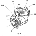
- FIG. 1a shows a schematic view of a gas control device 10 according to the invention for a ventilator 1.
- Respirators 1 usually have an inspiratory branch, which is intended for the supply of respiratory gas to a patient, and an expiratory branch, which is intended for the removal of respiratory gas exhaled by the patient serves.
- the gas control device (10) can be designed as an electrical and/or pneumatic control unit and set up to allow a pressurized gas stream to pass in a first direction (25) and a blocking the pressurized gas flow in a second direction (26) and blocking and/or at least temporarily enabling a gas flow from the first gas channel (11) to the bypass channel (21), a gas control device (10) being set up to control a gas flow from the first gas channel 11 to the bypass channel (21) to block and / or at least temporarily allow.
- the gas control device 10 is intended for use in a ventilator 1 or as part of a ventilator and has a first gas channel 11 with a first valve (19), the first gas channel (11) and the valve (19) being configured to have a lower to allow pressurized gas flow to pass in a first direction (25) and to block pressurized gas flow in a second direction (26), an orifice (14) branching off from the first gas channel 11 and leading to a bypass channel (21) for the valve (19), with a second valve (15, 16) being set up to block and/or at least temporarily enable a gas flow from the first gas duct (11) to the bypass duct (21), with a switching device (13) the second valve (15, 16) is set up to control, block and/or at least temporarily allow a gas flow from the first gas channel 11 to the bypass channel (21).
- the switching device here includes, for example, the valve block 13 with the first 19 and second valve, the first 11 and second gas path and the bypass 14, 21.
- the switching device 13 also includes the pneumatic or electronic control for the components of the valve block.
- the gas flow passes through the open check valve (19).
- the breathing gas flows in a second direction (26) through the breathing tube, the connection piece (28) and the first gas channel (11) to the non-return valve (19).
- This is a pneumatically operated non-return valve (19) which is actuated by the force of the pressurized expiratory gas flow in the second direction (26) and so cannot pass the non-return valve (19). Since the opening (14) communicating with the first gas channel (11), the pressurized expiration gas flow, in the second direction (26), also propagates into the orifice and reaches the valve (15, 16). If the switching device (13) opens the valve (15,16), the pressurized expiratory gas flow continues along the opening and the bypass channel (21) into the first gas channel and from there at least partially into the environment.
- the valve (15, 16) can be designed as a pneumatic valve.
- a seal (15) of the valve can close or open the gas-conducting connection between opening 14 and the surrounding channel.
- the control impulse for the seal (15) of the valve comes from a second gas channel (12) which directs a pneumatic control pressure to the surface of the seal 15. When the control pressure is applied to the seal, it seals against the edge 22 of the opening 14 and thus prevents gas flow from the opening into the bypass channel.
- the second gas channel can be from the breathing tube or. the gas channel (11) are fed pneumatically. Another compressed gas source, such as a control fan, is also conceivable.
- the switching device 13 opens or closes the pneumatic connection between the second gas channel 12 and the breathing tube or the gas channel (11), at least temporarily.
- the valve (15, 16) can be designed as a switching valve. In this case, activation of the valve, by the switching device 13, opens or closes the flow of gas from the opening 14 into the bypass channel. In this case, a second gas channel is unnecessary.
- Respirators generally have an inspiratory branch, which is provided for supplying respiratory gas to a patient, and an expiratory branch, which is used to discharge respiratory gas exhaled by the patient.
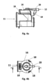
- Figure 1b shows a schematic view of an inventive
- Gas control device 10 for a ventilator for a ventilator.
- the gas control device (10) is only partially shown here, namely as a switching device 13 or as a valve block and comprises a first gas channel (11) with a first valve (19), the first gas channel (11) and the valve (19) being configured as a pressurized gas stream in a first direction (25) and to block a pressurized gas flow in a second direction (26), an opening (14) branching off from the first gas channel 11 and to a bypass channel (21) for the valve (19), leads, and a second valve (15, 16) to open or close the bypass channel (21).
- the gas control device 10 is intended for use in a ventilator and has a first gas channel 11 (inspiratory branch) which guides a gas flow in the direction of a patient.
- the first gas channel 11 includes a check valve 19 and a - not shown - opening with a - not shown- seal.
- the opening and the seal are in the figure 1 covered by a cap 16.
- the non-return valve 19 prevents a recirculation of a breathing gas/gas stream coming from the patient and contaminated by exhalation.
- the gas control device 10 has a second gas channel 12, which leads a gas flow to the opening—not shown.
- the second gas channel 12 is connected via a connection 20 to the closure cap 16 which is clipped onto the opening of the first gas channel.
- the second gas channel 12 runs via the connection 20 to the closure cap 16 and is controlled by a switching device--not shown--.
- a gas stream can flow through the second gas channel 12 .
- the switching device releases the second gas channel 12 for a gas flow or a gas pressure or a gas flow volume.
- the second gas channel 12 is released, so that the gas flow or pressure can be guided via the connection 20 to the seal—not shown—inside the closure cap 16 .
- the gas flow/pressure of the second gas channel 12 presses the seal completely onto the opening and the opening is thus closed.
- an inspiratory gas flow from the first gas channel 11, which is to be routed to the patient is prevented from escaping via the opening into the bypass channel 21. This is not necessary in this case because the expiratory branch is free of blockages, so that the patient's expired breathing gas can be delivered via the expiratory branch.
- the switching device blocks the second gas duct 12.
- the gas flow in the second gas duct 12, which acts on the seal comes to a standstill through the blocked gas duct 12, as a result of which the gas flow in the first gas duct 11 closes the seal, which rests on the opening, so that the gas flow of the first gas channel is guided around the non-return valve via a bypass channel 21 .
- the gas flow or pressure of the first gas channel 11 is greater than the gas flow or pressure of the second gas channel 12, as a result of which the gas flow of the first gas channel 11 can lift the seal that rests on the opening.
- the seal is dimensioned and designed in such a way that the gas flow of the first gas channel 11 can lift it when the gas channel 12 is blocked. Lifting means that the seal is held at its peripheral edge by the closure cap 16 on the edge of the bypass channel 21 and is pushed up towards the center of the circular seal by the gas flow of the first gas channel 11 .
- the weight of the seal is proportioned in such a way that when the gas flow of the second gas channel 12 decreases, it automatically deposits the seal on the opening.
- the patient can therefore exhale even if the expiratory branch is blocked/disturbed.
- the switching device blocks the second gas channel or does not apply any pressure to the seal.
- the switching valve is set up to permanently allow gas to flow out.
- the switching device is set up to switch according to the time-controlled expiration of the ventilator.
- the switching device set up to block the second gas channel 12 when the ventilator is switched to an expiration. This ensures expiration of a patient since the opening of the gas control device is open during expiration and backflowing gas can escape via the opening.
- the switching device activates the second gas channel 12, as a result of which a gas flow can flow into the second gas channel 12 and a pressure is applied thereto.
- the gas flow in the second gas channel 12 seals the seal on the opening, preventing inspiratory gas from escaping through the opening during normal operation
- the closure cap 16 comprises three extensions 18 by means of which the closure cap 16 can be clipped onto the opening of the first gas channel 11 .
- a connection 20 is formed on the closure cap, with which the second gas channel 12 can be connected.
- the connection 20 is arranged centrally on the closure cap 16 so that the gas flow/pressure can be applied centrally and evenly to the seal via the connection 20 and the closure cap 16 .
- the one in the Figure 1b The gas control device 10 shown is thus set up during normal operation to guide the gas flow in the first gas channel 11 through the non-return valve 19 to the patient. During normal operation of the expiratory branch, the opening of the first gas channel 11 is closed and the non-return valve 19 continues to function. If the check valve 19 is blocked/faulty, the gas control device 10 bypasses the check valve 19.
- the - not shown - switching device of the gas control device 10 is triggered by the time-controlled switching of the ventilator between inspiration and expiration.
- the switching device blocks the second gas channel 12 as soon as the ventilator switches to expiration.
- switching can be time-delayed.
- the switching device releases the second gas channel 12 when the ventilator switches to inspiration.
- bypass channel 21 is also shown.
- the bypass passage 21 extends from the orifice and allows the flow of gas exiting the orifice to bypass the check valve 19 .
- the bypass passage 21 is formed circumferentially around the opening and narrows as it progresses to a passage extending in a direction parallel to the first gas passage.
- the bypass duct 21 can then again open into the first gas duct or, as a separate branch, can discharge the gas flow that has passed the check valve.
- the bypass channel has an edge on which the seal can be sealed by the closure cap 16 .
- the edge of the bypass channel 21 can have a prominence behind which an edge of the seal can engage. The edge of the bypass channel 21 prevents the seal from slipping.
- figure 2 shows a schematic exploded view of in figure 1 shown gas control device 10.
- the first and the second gas channel 11, 12, the check valve 19 and the opening 14 with the seal 15 are shown.
- connection 20 The closure cap 16 with the connection 20 is also shown.
- the central arrangement of the connection 20 is shown, with one end of the connection 20 extending outwards and being able to be connected to the second gas channel 12 .
- Edge 22 is designed as an elevation and serves as a shelf for weight 17, which is integrated into seal 15.
- the seal 15 is made of an elastomeric material, preferably a silicone with a hardness of between 15 and 25 Shore A, in particular between 18 and 22 Shore A.
- the seal 15 is circular and has a boundary 23 .
- the border 23 can be designed as a reinforced structure or as a functional emphasis.
- the boundary 23 is set up to rest on an edge 24 of the bypass channel 21 .
- the seal 15 can have a thinner material thickness between the boundary 23 of the seal 15 and the weight 17 than in the area of the edge 24 of the bypass channel 21 and the area of the seal 15 in which the weight 17 is arranged, mostly integrally.
- the seal 15 between the edge 24 of the bypass channel 21 and the weight 17 has a curved structure, which can additionally prevent the seal 15 from being displaced on the opening 14 .
- the seal 15 between the edge 24 of the bypass channel 21 and the weight 17 can have a different structure or can be designed without a structure.
- the weight 17 of the seal 15 is in the form of a washer.
- the weight 17 is made of a metal and is integrally formed in the gasket 17 .
- the weight 17 stabilizes the seal 15 on the opening 14.
- the seal 15 When the closure cap 16 is placed on the opening 14, the seal 15 is pressed against the edge of the bypass channel 21 in the region of the boundary 23 of the seal 15 and held.
- the sealing cap 16 seals the seal 15 from the outside and holds the seal 15 in its position within the sealing cap 16.
- the seal 15 is thus pressed/held within the gas control device 10 by the clipped-on sealing cap 16 on the edge 24 of the bypass channel 21.
- the seal 15 is clamped/sealed between the edge 24 of the bypass channel 21 and the closure cap 16 via the reinforced border 23 formed all around.
- Areas of the seal 15 that differ from the boundary 23 are formed without contact with the closure cap 16 . These areas can also be referred to as impingement areas, since when the second gas channel 12 is released by the switching device, these areas of the seal 15 are subjected to a gas flow/pressure.
- the seal 15 is held in a resting state (without gas flows) on the opening 14 by the weight and its structure. If the switching device is set up to release the second gas duct 12 , the pressure areas of the seal 15 are also subjected to a gas flow/pressure, as a result of which the seal 15 is sealed off from the opening 14 .
- the switching device is set up to block the second gas channel 12, the pressure areas of the seal 15 are not subjected to a gas flow, so that the gas flow of the first gas channel 11 is sufficient to lift the seal in the area of the pressure areas and to direct the gas flow into the bypass channel 21 lead.
- Cap 16 shown includes extensions 18 that form barbs. When the closure cap 16 is clipped on, the barbs engage in recesses which are formed on the outside of the gas control device 10 . In further embodiments, further closure options are conceivable, for example latching in the form of a bayonet closure. Furthermore, in the figure 2 the check valve 19 and the bypass channel 21 are shown.
- FIG 3 shows a longitudinal section through the figures 1 and 2 shown.
- Gas control device 10 Shown is the first gas channel 11 with the check valve 19, the opening 14 and the seal 15 as well as the second gas channel 12.
- the closure cap 16 with the connection 20 and the bypass channel 21 are also shown.
- An inspiratory gas flow can be conveyed to the patient via the first gas channel 11 .
- the check valve 19 prevents exhaled gas from flowing back into the ventilator via the first gas channel 11 .
- the bypass channel 21 which extends from the opening 14 is also shown.
- the bypass channel 21 is formed as a peripheral channel around the opening 14 and extends in its further course to a channel in a direction parallel to the first gas channel 11 extends. Due to the circumferential arrangement of the bypass channel, a large quantity of exhaled gas can be discharged past the non-return valve 19 and via the opening 14 at the same time.
- the bypass channel 21 can open into the inspiratory branch or be designed as a separate expiratory branch.
- the seal 15 is circular and has a weight 17 at its center.
- the weight 17 is ring-shaped/washer-shaped. In its shape-related recess, the weight 17 has a conical configuration of the seal 15 which extends in the direction of the first gas channel 11 .
- the conical configuration offers the advantage that the seal 15 is secured against slipping in its position on the opening 14 .
- the configuration of the seal 15 can have a different geometric shape suitable for holding the seal 15 in position.
- the weight 17 is integrated into the seal 15 .
- the seal 15 has a greater material thickness in the area of the weight 17 . On the one hand, this offers the advantage that the weight 17 can be integrated into the seal 15 and, on the other hand, the greater material thickness produces an additional weight 17 that holds the seal 15 in its position.
- the weight 17 can also be applied to the seal 15 .
- the closure cap 16 shown is arranged on the opening 14, with the closure cap 16 pressing the seal 15 onto the edge of the bypass channel 21 in the area of the boundary 23, while the seal 15 is arranged without contact with the closure cap 16 in the impact areas.
- Figure 4a shows a side view of in the Figures 1 to 3 shown gas control device 10. Shown is the first gas channel 11 and the cap 16 with the extensions 18 and the connection 20 for the - not shown - second gas channel.
- the inlet side of the first gas channel 11 is larger than the outlet side.
- the input side also includes the bypass channel 21 narrowed to form a channel.
- the input side of the first gas channel 11 therefore includes both the first gas channel 11 oriented in the inspiration flow direction Gas channel 11 and the bypass channel 21, which is oriented counter to the inspiration flow direction.
- Figure 4b shows a plan view of the closure cap 16 according to the invention in FIGS Figures 1 to 4b shown gas control device 10 according to the invention.
- the cap 16 is on the - clipped opening of the first gas channel - not shown.
- the seal in the area of the weight (not shown) of the closure cap 16 is pushed onto a - in figure 3 shown - elevation 22 of the opening pressed and sealed.
- the closure cap 16 has a connection 20 for the second gas channel 12 (not shown).
- the gas stream of the second gas channel 12 (not shown) can be applied to the seal (not shown) via the connection 20 in order to close the opening (not shown).
- the closure cap 16 also includes the extensions 18 which mostly form barbs and are set up to engage in recesses in the area of the opening.
- the closure cap 16 can have further extensions 18 or can be fastened to the opening via similar latching elements.
- Figure 4c shows a plan view of the check valve 19 in FIGS Figures 1 to 4b shown gas control device 10 according to the invention.
- the check valve 19 is viewed from the direction of the inflowing gas flow, in the inspiration flow direction.
- the bypass channel 21 is also shown, via which the gas flow can be guided around the non-return valve 19 in the event of a blockage/fault in the expiratory branch of the ventilator.
- closure cap 16 is also shown in a side view with the extensions 18 by means of which the closure cap 16 can be clipped onto the opening (not shown).
Landscapes
- Health & Medical Sciences (AREA)
- Pulmonology (AREA)
- Heart & Thoracic Surgery (AREA)
- Engineering & Computer Science (AREA)
- Anesthesiology (AREA)
- Biomedical Technology (AREA)
- Emergency Medicine (AREA)
- Hematology (AREA)
- Life Sciences & Earth Sciences (AREA)
- Animal Behavior & Ethology (AREA)
- General Health & Medical Sciences (AREA)
- Public Health (AREA)
- Veterinary Medicine (AREA)
- Respiratory Apparatuses And Protective Means (AREA)
- Lift Valve (AREA)
Claims (11)
- Dispositif de commande de gaz (10) pour un appareil respiratoire (1) avec source de gaz respiratoire (30) et tube respiratoire (27) comprenant un premier canal de gaz (11) avec une première soupape (19), le premier canal de gaz (11) et la soupape (19) étant agencés pour laisser passer un flux de gaz sous pression dans une première direction (25) et pour bloquer un flux de gaz sous pression dans une deuxième direction (26), le flux de gaz de la deuxième direction (26) étant le gaz respiratoire de l'expiration et le flux de gaz dans la première direction (25) étant le gaz respiratoire de l'inspiration, une ouverture (14) bifurquant du premier canal de gaz (11) et conduisant à un canal de dérivation (21), pour la soupape (19), une deuxième soupape (15, 16) étant agencée pour bloquer et/ou permettre au moins temporairement un flux de gaz du premier canal de gaz (11) vers le canal de dérivation (21), un dispositif de commutation (13) étant agencé pour commander la deuxième soupape (15, 16), pour bloquer et/ou permettre au moins temporairement un flux de gaz du premier canal de gaz (11) vers le canal de dérivation (21), et en ce que la soupape (15, 16) est réalisée comme une soupape pneumatique, un joint (15) de la soupape fermant ou ouvrant le raccordement conducteur de gaz entre l'ouverture (14) et le canal de dérivation (21), et un deuxième canal de gaz (12) étant agencé pour diriger une pression de commande pneumatique sur la surface du joint (15), et en ce que le deuxième canal de gaz (12) est raccordé de façon pneumatique avec le tube respiratoire (27) ou le canal de gaz (11) ou la source de gaz respiratoire (30) et le dispositif de commutation (13) étant agencé pour ouvrir ou fermer au moins temporairement le raccordement pneumatique, caractérisé en ce que le dispositif de commutation (13) est agencé pour fermer le deuxième canal de gaz (12) lors d'un blocage ou d'une défaillance d'une branche expiratoire de l'appareil respiratoire qui empêche ou entrave une expiration du patient, de telle sorte que, par le canal de gaz (12) fermé, le flux de gaz du deuxième canal de gaz (12) agissant sur le joint (15) s'arrête, ce par quoi le flux de gaz du premier canal de gaz (11) peut soulever le joint reposant sur l'ouverture, de telle sorte que le flux de gaz du premier canal de gaz est conduit par un canal de dérivation (21) dans le premier canal de gaz (11) autour de la première soupape (19) et étant conduit au moins partiellement vers l'environnement à partir de celui-ci.
- Dispositif de commande de gaz (10) selon la revendication 1, caractérisé en ce que la première soupape est un clapet antiretour (19) actionné de façon pneumatique, lequel est actionné par la force du flux de gaz sous pression dans la deuxième direction (26) et le flux de gaz ne pouvant ainsi pas passer le clapet antiretour (19) dans une deuxième direction (26).
- Dispositif de commande de gaz (10) selon l'une des revendications précédentes, caractérisé en ce que la source de gaz respiratoire (30) aspire du gaz respiratoire de l'environnement (29) et le transporte le long du premier canal de gaz (11) pour l'inspiration dans la première direction (25) à un embout de tube (28) et au tube respiratoire (27), le flux de gaz passant le clapet antiretour (19) ouvert.
- Dispositif de commande de gaz (10) selon l'une des revendications précédentes, caractérisé en ce que le joint (15) auquel la pression de commande est appliquée est agencé pour s'appliquer de façon étanche au bord (22) de l'ouverture (14) et pour empêcher ainsi un flux de gaz de l'ouverture vers le canal de dérivation (21).
- Dispositif de commande de gaz (10) selon l'une des revendications précédentes, caractérisé en ce que le premier canal de gaz (11) présente l'ouverture (14) pour l'écoulement du gaz avec le joint (15) et un bouchon de fermeture (16).
- Dispositif de commande de gaz (10) selon l'une des revendications précédentes, caractérisé en ce que le joint (15) est disposé en appui sur l'ouverture (14) et comprend un poids (17), le poids (17) étant conçu de façon annulaire au milieu du joint (15) et le joint (15) étant composé d'un matériau élastomère et le poids (17) étant composé d'un métal.
- Dispositif de commande de gaz (10) selon l'une des revendications précédentes, caractérisé en ce que le joint (15) présente une empreinte qui est conçue avec orientation dans la direction du premier canal de gaz (11) dans la zone du poids (17).
- Dispositif de commande de gaz (10) selon la revendication 5, caractérisé en ce que le bouchon de fermeture (16) est agencé pour pouvoir être placé sur l'ouverture (14) et le bouchon de fermeture (16) comprenant un raccord (20), lequel est raccordable avec le deuxième canal de gaz (12).
- Dispositif de commande de gaz (10) selon la revendication 8, caractérisé en ce que le dispositif de commutation (13) est agencé pour ouvrir le deuxième canal de gaz (12) pendant un fonctionnement normal de la branche expiratoire et pour conduire un flux de gaz/une pression par le deuxième canal de gaz (12) et le raccord (20) au joint (15) et pour fermer l'ouverture (14).
- Dispositif de commande de gaz (10) selon la revendication 6, caractérisé en ce que la soupape (15, 16) est agencée pour permettre à un flux de gaz du premier canal de gaz (11) un passage par l'ouverture (14), lorsqu'un deuxième canal de gaz (12) est fermé.
- Appareil respiratoire comprenant un dispositif de commande de gaz (10) selon l'une des revendications précédentes.
Priority Applications (1)
| Application Number | Priority Date | Filing Date | Title |
|---|---|---|---|
| EP23193340.9A EP4272791A3 (fr) | 2018-07-06 | 2019-07-05 | Dispositif de commande de gaz pour un appareil respiratoire |
Applications Claiming Priority (2)
| Application Number | Priority Date | Filing Date | Title |
|---|---|---|---|
| DE102018005341 | 2018-07-06 | ||
| PCT/DE2019/000186 WO2020007389A1 (fr) | 2018-07-06 | 2019-07-05 | Dispositif de commande de gaz pour un appareil respiratoire |
Related Child Applications (1)
| Application Number | Title | Priority Date | Filing Date |
|---|---|---|---|
| EP23193340.9A Division EP4272791A3 (fr) | 2018-07-06 | 2019-07-05 | Dispositif de commande de gaz pour un appareil respiratoire |
Publications (2)
| Publication Number | Publication Date |
|---|---|
| EP3817800A1 EP3817800A1 (fr) | 2021-05-12 |
| EP3817800B1 true EP3817800B1 (fr) | 2023-09-06 |
Family
ID=67514261
Family Applications (2)
| Application Number | Title | Priority Date | Filing Date |
|---|---|---|---|
| EP19748647.5A Active EP3817800B1 (fr) | 2018-07-06 | 2019-07-05 | Dispositif de commande de gaz pour un appareil respiratoire |
| EP23193340.9A Pending EP4272791A3 (fr) | 2018-07-06 | 2019-07-05 | Dispositif de commande de gaz pour un appareil respiratoire |
Family Applications After (1)
| Application Number | Title | Priority Date | Filing Date |
|---|---|---|---|
| EP23193340.9A Pending EP4272791A3 (fr) | 2018-07-06 | 2019-07-05 | Dispositif de commande de gaz pour un appareil respiratoire |
Country Status (6)
| Country | Link |
|---|---|
| US (1) | US20210275763A1 (fr) |
| EP (2) | EP3817800B1 (fr) |
| JP (1) | JP7137701B2 (fr) |
| CN (1) | CN112601569A (fr) |
| DE (1) | DE112019003439A5 (fr) |
| WO (1) | WO2020007389A1 (fr) |
Family Cites Families (15)
| Publication number | Priority date | Publication date | Assignee | Title |
|---|---|---|---|---|
| US3933171A (en) * | 1974-04-09 | 1976-01-20 | Airco, Inc. | Anesthesia breathing circuit with positive end expiratory pressure valve |
| US5360000A (en) * | 1987-03-19 | 1994-11-01 | Puritan-Bennett Corporation | Pneumatic demand oxygen valve |
| AUPN973596A0 (en) * | 1996-05-08 | 1996-05-30 | Resmed Limited | Control of delivery pressure in cpap treatment or assisted respiration |
| US6098622A (en) * | 1998-10-15 | 2000-08-08 | Ntc Technology Inc. | Airway valve to facilitate re-breathing, method of operation, and ventilator circuit so equipped |
| GB0317801D0 (en) * | 2003-07-30 | 2003-09-03 | Intersurgical Ltd | Improvements relating to exhalation valves |
| DE102008026321A1 (de) * | 2007-06-14 | 2008-12-18 | Weinmann Geräte für Medizin GmbH & Co. KG | Patientenventil |
| DE202011102764U1 (de) * | 2011-07-02 | 2011-12-05 | Dräger Medical GmbH | Beatmungssystem |
| US20130167843A1 (en) * | 2011-12-31 | 2013-07-04 | Nellcor Puritan Bennett Llc | Piezoelectric blower piloted valve |
| GB201306067D0 (en) * | 2013-04-04 | 2013-05-22 | Smiths Medical Int Ltd | Resuscitator arrangements and flow monitoring |
| EP2805748B1 (fr) * | 2013-05-24 | 2018-09-26 | Drägerwerk AG & Co. KGaA | Masque respiratoire doté d'une soupape de respiration de secours |
| CN106563199B (zh) * | 2015-10-08 | 2020-02-04 | 北京谊安医疗系统股份有限公司 | 一种用于呼吸机的呼吸阀 |
| DE102016001140A1 (de) * | 2016-02-03 | 2017-08-03 | Drägerwerk AG & Co. KGaA | Exspirationsventil, Inspirationsventil, Beatmungsgerät und Verfahren zur Steuerung einer Beatmung |
| CN107308531B (zh) * | 2017-08-09 | 2020-01-17 | 深圳融昕医疗科技有限公司 | 呼吸机及其多功能吸气阀 |
| DE202017005964U1 (de) * | 2017-11-17 | 2017-12-14 | Drägerwerk AG & Co. KGaA | Rückschlagventil für ein Kompaktbeatmungssystem sowie Kompaktbeatmungssystem |
| DE102019104985A1 (de) * | 2018-03-08 | 2019-09-12 | Löwenstein Medical Technology S.A. | Beatmungsgerät mit Schaltventil |
-
2019
- 2019-07-05 CN CN201980054582.2A patent/CN112601569A/zh active Pending
- 2019-07-05 WO PCT/DE2019/000186 patent/WO2020007389A1/fr unknown
- 2019-07-05 EP EP19748647.5A patent/EP3817800B1/fr active Active
- 2019-07-05 US US17/257,916 patent/US20210275763A1/en active Pending
- 2019-07-05 JP JP2021521881A patent/JP7137701B2/ja active Active
- 2019-07-05 DE DE112019003439.1T patent/DE112019003439A5/de active Pending
- 2019-07-05 EP EP23193340.9A patent/EP4272791A3/fr active Pending
Also Published As
| Publication number | Publication date |
|---|---|
| WO2020007389A1 (fr) | 2020-01-09 |
| CN112601569A (zh) | 2021-04-02 |
| JP7137701B2 (ja) | 2022-09-14 |
| EP3817800A1 (fr) | 2021-05-12 |
| EP4272791A3 (fr) | 2023-12-20 |
| EP4272791A2 (fr) | 2023-11-08 |
| JP2021533953A (ja) | 2021-12-09 |
| DE112019003439A5 (de) | 2021-03-18 |
| US20210275763A1 (en) | 2021-09-09 |
Similar Documents
| Publication | Publication Date | Title |
|---|---|---|
| EP1960025B1 (fr) | Systeme de conduits flexibles pour appareils respiratoires | |
| DE102010048317B4 (de) | Künstliche Nase mit Sprechventil | |
| DE60316211T2 (de) | Vorrichtung zur Atmungsunterstützung | |
| DE60022783T2 (de) | Vorrichtung zur verabreichung eines gases an einen menschen oder ein tier | |
| WO2014060242A1 (fr) | Valve de phonation destinée à une canule de trachéotomie | |
| DE102011011874A1 (de) | Therapiegerät | |
| DE102012111281A1 (de) | Verdampferfülleinrichtung und Verfahren zum Füllen eines Verdampfers | |
| WO2017072363A1 (fr) | Masque respiratoire et dispositif de respiration | |
| EP3536369A1 (fr) | Appareil respiratoire à soupape de commande | |
| DE10046872A1 (de) | Atmungsunterstützungsvorrichtung | |
| EP3624884B1 (fr) | Ensemble clapet d'expiration pour un dispositif respiratoire, doté d'un dispositif pour recevoir un capteur de pression | |
| DE19931807C1 (de) | Beatmungsvorrichtung mit einem Überdruckventil | |
| EP3817800B1 (fr) | Dispositif de commande de gaz pour un appareil respiratoire | |
| EP4007628B1 (fr) | Ensemble de valve de gaz respiratoire à travers lequel un gaz respiratoire peut s'écouler de manière bidirectionnelle, et dispositif de ventilation comprenant un tel ensemble de valve | |
| EP3624883A1 (fr) | Soupape d'expiration d'un dispositif respiratoire avec résistance à l'écoulement minimisant les bruits | |
| DE3720482C2 (fr) | ||
| EP2932995B1 (fr) | Système d'insufflation | |
| WO2020007388A1 (fr) | Dispositif de commande de gaz sans conversion destiné à un appareil de ventilation | |
| DE102017005805A1 (de) | Beatmungsgerät und Verfahren | |
| EP0911050A2 (fr) | Elément de conduite pour la connection d'au moins une conduite de gaz respiratoire à un patient | |
| EP2543406B1 (fr) | Système de respiration | |
| EP3302662B1 (fr) | Agencement présentant un élément d'inversion de flux de gaz et raccord commutable | |
| DE102015010684A1 (de) | Nasenmaske zum Zuführen eines Gases in Nasenöffnungen eines Probanden | |
| EP3551267B1 (fr) | Échangeur de chaleur et d'humidité | |
| DE202007003817U1 (de) | Vorrichtung zur Flowsteuerung |
Legal Events
| Date | Code | Title | Description |
|---|---|---|---|
| STAA | Information on the status of an ep patent application or granted ep patent |
Free format text: STATUS: UNKNOWN |
|
| STAA | Information on the status of an ep patent application or granted ep patent |
Free format text: STATUS: THE INTERNATIONAL PUBLICATION HAS BEEN MADE |
|
| STAA | Information on the status of an ep patent application or granted ep patent |
Free format text: STATUS: THE INTERNATIONAL PUBLICATION HAS BEEN MADE |
|
| PUAI | Public reference made under article 153(3) epc to a published international application that has entered the european phase |
Free format text: ORIGINAL CODE: 0009012 |
|
| STAA | Information on the status of an ep patent application or granted ep patent |
Free format text: STATUS: REQUEST FOR EXAMINATION WAS MADE |
|
| 17P | Request for examination filed |
Effective date: 20210129 |
|
| AK | Designated contracting states |
Kind code of ref document: A1 Designated state(s): AL AT BE BG CH CY CZ DE DK EE ES FI FR GB GR HR HU IE IS IT LI LT LU LV MC MK MT NL NO PL PT RO RS SE SI SK SM TR |
|
| DAV | Request for validation of the european patent (deleted) | ||
| DAX | Request for extension of the european patent (deleted) | ||
| GRAP | Despatch of communication of intention to grant a patent |
Free format text: ORIGINAL CODE: EPIDOSNIGR1 |
|
| STAA | Information on the status of an ep patent application or granted ep patent |
Free format text: STATUS: GRANT OF PATENT IS INTENDED |
|
| INTG | Intention to grant announced |
Effective date: 20230512 |
|
| P01 | Opt-out of the competence of the unified patent court (upc) registered |
Effective date: 20230523 |
|
| GRAS | Grant fee paid |
Free format text: ORIGINAL CODE: EPIDOSNIGR3 |
|
| GRAA | (expected) grant |
Free format text: ORIGINAL CODE: 0009210 |
|
| STAA | Information on the status of an ep patent application or granted ep patent |
Free format text: STATUS: THE PATENT HAS BEEN GRANTED |
|
| AK | Designated contracting states |
Kind code of ref document: B1 Designated state(s): AL AT BE BG CH CY CZ DE DK EE ES FI FR GB GR HR HU IE IS IT LI LT LU LV MC MK MT NL NO PL PT RO RS SE SI SK SM TR |
|
| REG | Reference to a national code |
Ref country code: GB Ref legal event code: FG4D Free format text: NOT ENGLISH |
|
| REG | Reference to a national code |
Ref country code: CH Ref legal event code: EP |
|
| REG | Reference to a national code |
Ref country code: IE Ref legal event code: FG4D Free format text: LANGUAGE OF EP DOCUMENT: GERMAN |
|
| REG | Reference to a national code |
Ref country code: DE Ref legal event code: R096 Ref document number: 502019009285 Country of ref document: DE |
|
| REG | Reference to a national code |
Ref country code: NL Ref legal event code: FP |
|
| REG | Reference to a national code |
Ref country code: LT Ref legal event code: MG9D |
|
| PG25 | Lapsed in a contracting state [announced via postgrant information from national office to epo] |
Ref country code: GR Free format text: LAPSE BECAUSE OF FAILURE TO SUBMIT A TRANSLATION OF THE DESCRIPTION OR TO PAY THE FEE WITHIN THE PRESCRIBED TIME-LIMIT Effective date: 20231207 |
|
| PG25 | Lapsed in a contracting state [announced via postgrant information from national office to epo] |
Ref country code: SE Free format text: LAPSE BECAUSE OF FAILURE TO SUBMIT A TRANSLATION OF THE DESCRIPTION OR TO PAY THE FEE WITHIN THE PRESCRIBED TIME-LIMIT Effective date: 20230906 Ref country code: RS Free format text: LAPSE BECAUSE OF FAILURE TO SUBMIT A TRANSLATION OF THE DESCRIPTION OR TO PAY THE FEE WITHIN THE PRESCRIBED TIME-LIMIT Effective date: 20230906 Ref country code: NO Free format text: LAPSE BECAUSE OF FAILURE TO SUBMIT A TRANSLATION OF THE DESCRIPTION OR TO PAY THE FEE WITHIN THE PRESCRIBED TIME-LIMIT Effective date: 20231206 Ref country code: LV Free format text: LAPSE BECAUSE OF FAILURE TO SUBMIT A TRANSLATION OF THE DESCRIPTION OR TO PAY THE FEE WITHIN THE PRESCRIBED TIME-LIMIT Effective date: 20230906 Ref country code: LT Free format text: LAPSE BECAUSE OF FAILURE TO SUBMIT A TRANSLATION OF THE DESCRIPTION OR TO PAY THE FEE WITHIN THE PRESCRIBED TIME-LIMIT Effective date: 20230906 Ref country code: HR Free format text: LAPSE BECAUSE OF FAILURE TO SUBMIT A TRANSLATION OF THE DESCRIPTION OR TO PAY THE FEE WITHIN THE PRESCRIBED TIME-LIMIT Effective date: 20230906 Ref country code: GR Free format text: LAPSE BECAUSE OF FAILURE TO SUBMIT A TRANSLATION OF THE DESCRIPTION OR TO PAY THE FEE WITHIN THE PRESCRIBED TIME-LIMIT Effective date: 20231207 Ref country code: FI Free format text: LAPSE BECAUSE OF FAILURE TO SUBMIT A TRANSLATION OF THE DESCRIPTION OR TO PAY THE FEE WITHIN THE PRESCRIBED TIME-LIMIT Effective date: 20230906 |
|
| PG25 | Lapsed in a contracting state [announced via postgrant information from national office to epo] |
Ref country code: IS Free format text: LAPSE BECAUSE OF FAILURE TO SUBMIT A TRANSLATION OF THE DESCRIPTION OR TO PAY THE FEE WITHIN THE PRESCRIBED TIME-LIMIT Effective date: 20240106 |
|
| PG25 | Lapsed in a contracting state [announced via postgrant information from national office to epo] |
Ref country code: ES Free format text: LAPSE BECAUSE OF FAILURE TO SUBMIT A TRANSLATION OF THE DESCRIPTION OR TO PAY THE FEE WITHIN THE PRESCRIBED TIME-LIMIT Effective date: 20230906 |
|
| PG25 | Lapsed in a contracting state [announced via postgrant information from national office to epo] |
Ref country code: SM Free format text: LAPSE BECAUSE OF FAILURE TO SUBMIT A TRANSLATION OF THE DESCRIPTION OR TO PAY THE FEE WITHIN THE PRESCRIBED TIME-LIMIT Effective date: 20230906 Ref country code: RO Free format text: LAPSE BECAUSE OF FAILURE TO SUBMIT A TRANSLATION OF THE DESCRIPTION OR TO PAY THE FEE WITHIN THE PRESCRIBED TIME-LIMIT Effective date: 20230906 Ref country code: IS Free format text: LAPSE BECAUSE OF FAILURE TO SUBMIT A TRANSLATION OF THE DESCRIPTION OR TO PAY THE FEE WITHIN THE PRESCRIBED TIME-LIMIT Effective date: 20240106 Ref country code: ES Free format text: LAPSE BECAUSE OF FAILURE TO SUBMIT A TRANSLATION OF THE DESCRIPTION OR TO PAY THE FEE WITHIN THE PRESCRIBED TIME-LIMIT Effective date: 20230906 Ref country code: EE Free format text: LAPSE BECAUSE OF FAILURE TO SUBMIT A TRANSLATION OF THE DESCRIPTION OR TO PAY THE FEE WITHIN THE PRESCRIBED TIME-LIMIT Effective date: 20230906 Ref country code: CZ Free format text: LAPSE BECAUSE OF FAILURE TO SUBMIT A TRANSLATION OF THE DESCRIPTION OR TO PAY THE FEE WITHIN THE PRESCRIBED TIME-LIMIT Effective date: 20230906 Ref country code: PT Free format text: LAPSE BECAUSE OF FAILURE TO SUBMIT A TRANSLATION OF THE DESCRIPTION OR TO PAY THE FEE WITHIN THE PRESCRIBED TIME-LIMIT Effective date: 20240108 Ref country code: SK Free format text: LAPSE BECAUSE OF FAILURE TO SUBMIT A TRANSLATION OF THE DESCRIPTION OR TO PAY THE FEE WITHIN THE PRESCRIBED TIME-LIMIT Effective date: 20230906 |