EP3817800B1 - Gas control device for a ventilator - Google Patents
Gas control device for a ventilator Download PDFInfo
- Publication number
- EP3817800B1 EP3817800B1 EP19748647.5A EP19748647A EP3817800B1 EP 3817800 B1 EP3817800 B1 EP 3817800B1 EP 19748647 A EP19748647 A EP 19748647A EP 3817800 B1 EP3817800 B1 EP 3817800B1
- Authority
- EP
- European Patent Office
- Prior art keywords
- gas
- channel
- seal
- opening
- gas channel
- Prior art date
- Legal status (The legal status is an assumption and is not a legal conclusion. Google has not performed a legal analysis and makes no representation as to the accuracy of the status listed.)
- Active
Links
- 230000029058 respiratory gaseous exchange Effects 0.000 claims description 21
- 238000007789 sealing Methods 0.000 claims description 9
- 239000000463 material Substances 0.000 claims description 6
- 238000009423 ventilation Methods 0.000 claims description 5
- 239000002184 metal Substances 0.000 claims description 4
- 229920001971 elastomer Polymers 0.000 claims 1
- 239000000806 elastomer Substances 0.000 claims 1
- 239000007789 gas Substances 0.000 description 469
- 230000000241 respiratory effect Effects 0.000 description 22
- 230000003434 inspiratory effect Effects 0.000 description 18
- 230000002093 peripheral effect Effects 0.000 description 6
- 230000000903 blocking effect Effects 0.000 description 5
- 238000011161 development Methods 0.000 description 5
- 230000018109 developmental process Effects 0.000 description 5
- 208000037265 diseases, disorders, signs and symptoms Diseases 0.000 description 4
- 239000013536 elastomeric material Substances 0.000 description 4
- 230000007257 malfunction Effects 0.000 description 3
- 229920001296 polysiloxane Polymers 0.000 description 3
- 230000000284 resting effect Effects 0.000 description 3
- QVGXLLKOCUKJST-UHFFFAOYSA-N atomic oxygen Chemical compound [O] QVGXLLKOCUKJST-UHFFFAOYSA-N 0.000 description 2
- 238000004049 embossing Methods 0.000 description 2
- 238000005259 measurement Methods 0.000 description 2
- 239000012528 membrane Substances 0.000 description 2
- 239000000203 mixture Substances 0.000 description 2
- 239000001301 oxygen Substances 0.000 description 2
- 229910052760 oxygen Inorganic materials 0.000 description 2
- 230000007704 transition Effects 0.000 description 2
- 230000001133 acceleration Effects 0.000 description 1
- 230000004913 activation Effects 0.000 description 1
- 230000007423 decrease Effects 0.000 description 1
- 230000001419 dependent effect Effects 0.000 description 1
- 238000001595 flow curve Methods 0.000 description 1
- 230000014759 maintenance of location Effects 0.000 description 1
- 230000021715 photosynthesis, light harvesting Effects 0.000 description 1
- 230000036387 respiratory rate Effects 0.000 description 1
- 208000023504 respiratory system disease Diseases 0.000 description 1
- 230000000717 retained effect Effects 0.000 description 1
- 238000002560 therapeutic procedure Methods 0.000 description 1
- 230000001960 triggered effect Effects 0.000 description 1
- 238000011144 upstream manufacturing Methods 0.000 description 1
Images


Classifications
-
- A—HUMAN NECESSITIES
- A61—MEDICAL OR VETERINARY SCIENCE; HYGIENE
- A61M—DEVICES FOR INTRODUCING MEDIA INTO, OR ONTO, THE BODY; DEVICES FOR TRANSDUCING BODY MEDIA OR FOR TAKING MEDIA FROM THE BODY; DEVICES FOR PRODUCING OR ENDING SLEEP OR STUPOR
- A61M16/00—Devices for influencing the respiratory system of patients by gas treatment, e.g. mouth-to-mouth respiration; Tracheal tubes
- A61M16/20—Valves specially adapted to medical respiratory devices
- A61M16/208—Non-controlled one-way valves, e.g. exhalation, check, pop-off non-rebreathing valves
- A61M16/209—Relief valves
-
- A—HUMAN NECESSITIES
- A61—MEDICAL OR VETERINARY SCIENCE; HYGIENE
- A61M—DEVICES FOR INTRODUCING MEDIA INTO, OR ONTO, THE BODY; DEVICES FOR TRANSDUCING BODY MEDIA OR FOR TAKING MEDIA FROM THE BODY; DEVICES FOR PRODUCING OR ENDING SLEEP OR STUPOR
- A61M16/00—Devices for influencing the respiratory system of patients by gas treatment, e.g. mouth-to-mouth respiration; Tracheal tubes
- A61M16/021—Devices for influencing the respiratory system of patients by gas treatment, e.g. mouth-to-mouth respiration; Tracheal tubes operated by electrical means
- A61M16/022—Control means therefor
-
- A—HUMAN NECESSITIES
- A61—MEDICAL OR VETERINARY SCIENCE; HYGIENE
- A61M—DEVICES FOR INTRODUCING MEDIA INTO, OR ONTO, THE BODY; DEVICES FOR TRANSDUCING BODY MEDIA OR FOR TAKING MEDIA FROM THE BODY; DEVICES FOR PRODUCING OR ENDING SLEEP OR STUPOR
- A61M16/00—Devices for influencing the respiratory system of patients by gas treatment, e.g. mouth-to-mouth respiration; Tracheal tubes
- A61M16/20—Valves specially adapted to medical respiratory devices
- A61M16/201—Controlled valves
- A61M16/202—Controlled valves electrically actuated
- A61M16/203—Proportional
- A61M16/205—Proportional used for exhalation control
-
- A—HUMAN NECESSITIES
- A61—MEDICAL OR VETERINARY SCIENCE; HYGIENE
- A61M—DEVICES FOR INTRODUCING MEDIA INTO, OR ONTO, THE BODY; DEVICES FOR TRANSDUCING BODY MEDIA OR FOR TAKING MEDIA FROM THE BODY; DEVICES FOR PRODUCING OR ENDING SLEEP OR STUPOR
- A61M16/00—Devices for influencing the respiratory system of patients by gas treatment, e.g. mouth-to-mouth respiration; Tracheal tubes
- A61M16/20—Valves specially adapted to medical respiratory devices
- A61M16/201—Controlled valves
- A61M16/206—Capsule valves, e.g. mushroom, membrane valves
-
- A—HUMAN NECESSITIES
- A61—MEDICAL OR VETERINARY SCIENCE; HYGIENE
- A61M—DEVICES FOR INTRODUCING MEDIA INTO, OR ONTO, THE BODY; DEVICES FOR TRANSDUCING BODY MEDIA OR FOR TAKING MEDIA FROM THE BODY; DEVICES FOR PRODUCING OR ENDING SLEEP OR STUPOR
- A61M16/00—Devices for influencing the respiratory system of patients by gas treatment, e.g. mouth-to-mouth respiration; Tracheal tubes
- A61M16/20—Valves specially adapted to medical respiratory devices
- A61M16/208—Non-controlled one-way valves, e.g. exhalation, check, pop-off non-rebreathing valves
-
- A—HUMAN NECESSITIES
- A61—MEDICAL OR VETERINARY SCIENCE; HYGIENE
- A61M—DEVICES FOR INTRODUCING MEDIA INTO, OR ONTO, THE BODY; DEVICES FOR TRANSDUCING BODY MEDIA OR FOR TAKING MEDIA FROM THE BODY; DEVICES FOR PRODUCING OR ENDING SLEEP OR STUPOR
- A61M16/00—Devices for influencing the respiratory system of patients by gas treatment, e.g. mouth-to-mouth respiration; Tracheal tubes
- A61M16/0057—Pumps therefor
- A61M16/0066—Blowers or centrifugal pumps
-
- A—HUMAN NECESSITIES
- A61—MEDICAL OR VETERINARY SCIENCE; HYGIENE
- A61M—DEVICES FOR INTRODUCING MEDIA INTO, OR ONTO, THE BODY; DEVICES FOR TRANSDUCING BODY MEDIA OR FOR TAKING MEDIA FROM THE BODY; DEVICES FOR PRODUCING OR ENDING SLEEP OR STUPOR
- A61M16/00—Devices for influencing the respiratory system of patients by gas treatment, e.g. mouth-to-mouth respiration; Tracheal tubes
- A61M16/0003—Accessories therefor, e.g. sensors, vibrators, negative pressure
- A61M2016/0027—Accessories therefor, e.g. sensors, vibrators, negative pressure pressure meter
-
- A—HUMAN NECESSITIES
- A61—MEDICAL OR VETERINARY SCIENCE; HYGIENE
- A61M—DEVICES FOR INTRODUCING MEDIA INTO, OR ONTO, THE BODY; DEVICES FOR TRANSDUCING BODY MEDIA OR FOR TAKING MEDIA FROM THE BODY; DEVICES FOR PRODUCING OR ENDING SLEEP OR STUPOR
- A61M16/00—Devices for influencing the respiratory system of patients by gas treatment, e.g. mouth-to-mouth respiration; Tracheal tubes
- A61M16/0003—Accessories therefor, e.g. sensors, vibrators, negative pressure
- A61M2016/003—Accessories therefor, e.g. sensors, vibrators, negative pressure with a flowmeter
- A61M2016/0033—Accessories therefor, e.g. sensors, vibrators, negative pressure with a flowmeter electrical
- A61M2016/0039—Accessories therefor, e.g. sensors, vibrators, negative pressure with a flowmeter electrical in the inspiratory circuit
-
- A—HUMAN NECESSITIES
- A61—MEDICAL OR VETERINARY SCIENCE; HYGIENE
- A61M—DEVICES FOR INTRODUCING MEDIA INTO, OR ONTO, THE BODY; DEVICES FOR TRANSDUCING BODY MEDIA OR FOR TAKING MEDIA FROM THE BODY; DEVICES FOR PRODUCING OR ENDING SLEEP OR STUPOR
- A61M16/00—Devices for influencing the respiratory system of patients by gas treatment, e.g. mouth-to-mouth respiration; Tracheal tubes
- A61M16/0003—Accessories therefor, e.g. sensors, vibrators, negative pressure
- A61M2016/003—Accessories therefor, e.g. sensors, vibrators, negative pressure with a flowmeter
- A61M2016/0033—Accessories therefor, e.g. sensors, vibrators, negative pressure with a flowmeter electrical
- A61M2016/0042—Accessories therefor, e.g. sensors, vibrators, negative pressure with a flowmeter electrical in the expiratory circuit
-
- A—HUMAN NECESSITIES
- A61—MEDICAL OR VETERINARY SCIENCE; HYGIENE
- A61M—DEVICES FOR INTRODUCING MEDIA INTO, OR ONTO, THE BODY; DEVICES FOR TRANSDUCING BODY MEDIA OR FOR TAKING MEDIA FROM THE BODY; DEVICES FOR PRODUCING OR ENDING SLEEP OR STUPOR
- A61M2205/00—General characteristics of the apparatus
- A61M2205/16—General characteristics of the apparatus with back-up system in case of failure
-
- A—HUMAN NECESSITIES
- A61—MEDICAL OR VETERINARY SCIENCE; HYGIENE
- A61M—DEVICES FOR INTRODUCING MEDIA INTO, OR ONTO, THE BODY; DEVICES FOR TRANSDUCING BODY MEDIA OR FOR TAKING MEDIA FROM THE BODY; DEVICES FOR PRODUCING OR ENDING SLEEP OR STUPOR
- A61M2205/00—General characteristics of the apparatus
- A61M2205/33—Controlling, regulating or measuring
- A61M2205/3331—Pressure; Flow
- A61M2205/3334—Measuring or controlling the flow rate
-
- A—HUMAN NECESSITIES
- A61—MEDICAL OR VETERINARY SCIENCE; HYGIENE
- A61M—DEVICES FOR INTRODUCING MEDIA INTO, OR ONTO, THE BODY; DEVICES FOR TRANSDUCING BODY MEDIA OR FOR TAKING MEDIA FROM THE BODY; DEVICES FOR PRODUCING OR ENDING SLEEP OR STUPOR
- A61M2205/00—General characteristics of the apparatus
- A61M2205/33—Controlling, regulating or measuring
- A61M2205/3368—Temperature
Definitions
- the present invention relates to a gas control device for a ventilator comprising a first gas channel with a check valve, a second gas channel and a switching device.
- the gas control device may be located in the ventilator or associated with the ventilator.
- Ventilators are used for the therapy of respiratory disorders.
- the ventilators can be used in non-invasive and invasive ventilation, both in-hospital and out-of-hospital.
- a ventilator When ventilating a patient, a ventilator with an inspiratory branch for the respiratory gas flow and optionally with a branch for the expiratory respiratory gas flow can usually be used.
- the expiratory flow branch allows the patient to exhale/exhale a breathing gas, while the inspiratory flow branch supplies breathing gas to the patient.
- the inspiratory branch of the ventilator includes a non-return valve, it is not possible to recycle exhaled respiratory gas into the ventilator. The patient is then prevented from exhaling.
- WO 2017/059667 and DE 20 2017 005964 disclose gas control devices for ventilators.
- the present invention relates to a gas control device for a ventilator comprising a first gas channel with a first valve, the first gas channel and the valve being set up to allow a pressurized gas flow to pass in a first direction and a pressurized gas flow in a second direction to block, wherein an opening branches off from the first gas channel and leads to a bypass channel for the valve, wherein a second valve is set up to block and/or at least temporarily enable a gas flow from the first gas channel to the bypass channel, wherein a Switching device is set up to control the second valve, to block a gas flow from the first gas duct to the bypass duct and/or to at least temporarily allow it.
- the present invention also relates to a gas control device comprising a first gas channel with a first valve, the first gas channel and the valve being arranged to allow a pressurized gas flow to pass in a first direction and to block a pressurized gas flow in a second direction , wherein an opening branches off from the first gas duct and leads to a bypass duct for the valve, wherein a second valve is set up to block and/or at least temporarily enable a gas flow from the first gas duct to the bypass duct, a switching device being set up the second valve is to be controlled to block and/or at least temporarily allow a gas flow from the first gas channel to the bypass channel.
- the present invention is also characterized in that the second direction is opposite to the first direction.
- the present invention is also characterized in that the first valve is a pneumatically actuated check valve which is actuated by the force of the pressurized gas flow in the second direction and thus the gas flow cannot pass the check valve in a second direction.
- the present invention is also characterized in that the gas flow of the second direction is respiratory gas of expiration and the gas flow of the first direction is respiratory gas of inspiration.
- the present invention is also characterized in that a respiratory gas source draws respiratory gas from the environment and conveys it along the first gas channel for inspiration in the first direction to the hose connector and the breathing tube, the gas flow passing through the opened check valve.
- the present invention is also characterized in that the switching device opens the valve and the pressurized gas flow of the expiration thus at least partially escapes through the opening and through the bypass channel into the environment.
- the present invention is also characterized in that the valve is designed as a pneumatic valve, with a seal of the valve closing or opening the gas-conducting connection between the opening and the surrounding channel, and with a second gas channel being set up to direct a pneumatic control pressure to the surface of the seal.
- the present invention is also characterized in that the seal subjected to the control pressure is arranged to sealingly abut the edge of the opening and thus prevent gas flow from the opening into the bypass duct.
- the present invention is also characterized in that the second gas channel is pneumatically connected to the breathing tube or the gas channel and the switching device at least temporarily opens or closes the pneumatic connection.
- the present invention also relates to a gas control device for a ventilator comprising a first gas channel with a check valve, a second gas channel and a switching device, the first gas channel having an opening for outflow of gas with a seal and a closure cap.
- the gas control device is set up to direct the gas flow of the first gas channel past the check valve in the event of a blockage/fault in an expiratory branch of the ventilator. This ensures that the patient can exhale in the event of a blockage/disorder in the expiratory branch.
- the first gas channel is connected to the second gas channel.
- a separate design of the first gas channel and the second gas channel, with the second gas channel being fed by a separate gas channel is conceivable in an alternative embodiment.
- the gas control device according to the invention in the event of a blockage/malfunction in an inspiratory branch of the ventilator. In such a case, the gas control device could be used to ensure inspiration of a patient in the event of a blockage/fault in the inspiratory branch of the ventilator.
- the gas control device is set up to control the second gas channel in the event of a blockage or disruption of the expiratory branch in such a way that the gas flow of the first gas channel flows out via the opening or flows past the check valve via a bypass channel.
- the gas flow of the first gas channel is usually made up of an inhaled gas and/or an exhaled gas.
- the exhaled gas of a patient can be fed back via the inspiratory branch/the first gas channel to the non-return valve.
- the opening of the first gas channel is therefore advantageously arranged downstream of the check valve in the area of the check valve in the inspiration flow direction.
- the gas control device is set up to control the pressure in the second gas channel.
- controlling can mean that the switching device can be set up to enable or block the second gas channel.
- the switching device can be continuously steplessly controlled.
- the gas flow of the first gas channel (the exhaled gas/the exhaled gas flow) can be guided past the check valve.
- the gas flow of the first gas channel is routed past the check valve via a bypass channel.
- the gas flow diverted into the bypass channel can again be fed to the first gas channel, advantageously in an area upstream of the check valve in the inspiration flow direction of the gas flow, or be discharged via the bypass channel or a separate branch, which can be set up as an inspiratory or expiratory branch.
- the gas control device can be set up to be controllable based on a detected volume, a detected flow rate or a detected pressure of a gas flow.
- the gas control device can include at least one sensor, wherein the switching device can be set up to be controllable based on a parameter detected by the at least one sensor.
- the at least one sensor of the gas control device can be set up to detect at least one respiration parameter, respiratory gas parameter and/or another parameter from output signals.
- One or more detected parameters can form a function relating, for example, to measurements of one or more of the following: (peak) flow, flow rate, (tidal) volume, pressure, temperature, humidity, velocity, acceleration, gas composition ( eg concentration(s) of one or more components), thermal energy dissipation, (intended) gas leakage and/or other measurements related to the respiratory gas flow.
- Respiratory parameters can be derived, for example, from gas parameters and/or other output signals, where one or more respiratory parameters can be one or more of the following: respiratory rate, respiratory duration, inspiration time or duration, expiration time or period, shape of the respiratory flow curve, transition time from the Inspiration to exhalation and/or vice versa, transition time from inspiratory (peak) flow rate to expiratory (peak) flow rate and/or vice versa, respiratory pressure waveform, maximum proximal pressure drop (per respiratory cycle and/or phase), fraction of inspired oxygen and/or other respiratory parameters .
- respiratory parameters can be one or more of the following: respiratory rate, respiratory duration, inspiration time or duration, expiration time or period, shape of the respiratory flow curve, transition time from the Inspiration to exhalation and/or vice versa, transition time from inspiratory (peak) flow rate to expiratory (peak) flow rate and/or vice versa, respiratory pressure waveform, maximum proximal pressure drop (per respiratory cycle and/or phase), fraction of inspired oxygen and/or other respiratory parameters .
- the gas control device enables a patient to be able to exhale even if the expiratory branch of the ventilator is blocked/disrupted.
- the gas control device for example via the switching device, is set up to control the gas flow of the second gas channel and to allow the gas flow of the first gas channel to bypass the check valve through the opening.
- the opening on which the seal rests which is sealed by the gas flow/pressure of the second gas channel, can be opened.
- the gas flow of the first gas channel can exit from the opening.
- the pressure ratio in the area of the seal changes, so that a gas pressure of the gas flow in the first gas channel is greater than a gas pressure in the second gas channel.
- the gas pressure of the blocked second gas channel is equal to zero.
- the bypass channel is designed in the shape of a ring around the opening of the first gas channel. Ring-shaped can also mean enclosing the opening.
- the ring-shaped configuration offers the advantage that gas can flow out of the opening at an angle of up to 360°. As a result, a correspondingly large amount of expiratory exhaled gas can be discharged at the same time via the opening of the first gas channel.
- the bypass channel is advantageously set up to bundle the gas flow discharged via the opening and to discharge it in one direction.
- the gas control device is set up, for example via the switching device, to enable or block the second gas channel.
- the switching device is set up to release the second gas channel, as a result of which a gas flow/pressure can be applied to the seal that rests on the opening.
- the switching device can also be set up to block the second gas channel, so that no gas flow/pressure can be applied to the seal that rests on the opening. In this case, the seal rests loosely on the opening. In this configuration, a gas flow from the first gas channel can flow through the seal lying loosely on the opening into a bypass channel.
- the gas control device is advantageously set up, for example via the switching device, to block the second gas channel in the event of a blockage/fault in the expiratory branch. Blocking means that the switching device does not provide any gas flow/pressure in the second gas channel or closes it. Because the seal is not subjected to a gas flow from the second gas channel, the gas flow from the first gas channel is sufficient to lift the seal and transfer the gas flow from the first gas channel into the bypass channel.
- the gas control device is set up, for example via the switching device, to release the second gas channel when the ventilator is used in a valve system, so that the second gas channel can conduct a gas flow.
- the expiratory and/or inspiratory branch of the ventilator is/are undisturbed and the opening of the gas control device is closed by a pressure of the second gas channel, which is usually designed as a pressure channel.
- Releasing means that the gas control device opens the second gas channel for a gas stream to flow through, for example via the switching device, and thus applies a gas stream/pressure to the seal that rests on the opening.
- the gas flow of the second gas channel is subjected to a pressure of 1 mbar to 100 mbar. The pressure pushes the seal onto the opening and seals it.
- the gas control device is set up, during normal operation of the ventilator, to seal off the gas flow from the first gas channel by means of the gas flow from the second gas channel, which is conducted via a connection of the closure cap onto the seal of the gas control device.
- the gas control device is set up to apply pressure via the second gas channel to the sealing membrane when the ventilator is in a fault-free operating state, for example with a fault-free expiratory branch, and thereby to close the opening of the gas control device.
- the gas control device is set up to shut off the second gas channel in the event of a blockage/fault in the expiratory branch. As a result, there is no pressure on the sealing membrane and the opening can be opened by a gas pressure of the gas flow of the first gas channel. The gas stream that exits via the opening can be fed back to the first gas channel or can be discharged via a separate branch.
- the switching device (as part of the gas control device) can be set up to be controllable based on a time-controlled switching of an expiration and/or an inspiration.
- the switching device (as part of the gas control device) can be configured to be controllable based on a parameter of the first gas channel.
- a parameter of the gas flow in the first gas channel can be detected by means of a sensor.
- a pressure within the first gas channel can be detected by means of a pressure sensor.
- the switching device is then set up to be controllable as a function of the detected pressure of the gas flow in the first gas channel.
- the switching device can be set up to enable or block the second gas channel depending on whether a predetermined threshold value is reached.
- a threshold value can, for example, be a value that is above the average pressure recorded in the first gas channel. If the threshold value is exceeded, the switching device can be set up to block the second gas channel. If the pressure in the first gas channel below the threshold value, the switching device can release the second gas channel.
- a sensor can also be used, for example, to detect the flow rate or a volume of the gas flow in the first gas channel.
- the switching device can be set up to be controllable based on the determined flow rate or the detected volume of the gas flow.
- the switching device can also be set up to be controllable based on further parameters of the gas flow of the first gas channel.
- the switching device (as part of the gas control device) can also be set up in a variably switchable manner, wherein the switching device can be set up to continuously control a pressure of the gas flow in the second gas channel between 0 mbar and 1 bar, in particular between 0 mbar and 100 mbar.
- the switching device can also be set up to increase the gas flow/pressure in the second gas channel continuously over a predetermined period of time to a predetermined value.
- the seal for part of the gas control device is designed to allow the gas stream of the first gas channel to flow through the opening when the second gas channel is blocked.
- the gasket seals the bypass passage against the opening.
- the seal advantageously has a shape that deposits and holds the seal on the opening in a gas-empty state of the first and second gas channels.
- the seal has a contact area ratio between 4 5 and 2 3 on.
- the seal is dimensioned in such a way that it can be lifted by a gas flow from the first gas channel when the seal is not subjected to a gas flow/pressure by a gas flow from the second gas channel.
- the seal typically includes a peripheral, reinforced rim that is adapted to rest on the rim of the bypass channel.
- the peripheral, reinforced rim may include a latch structure or retention structure that makes it easier to retain the seal on the rim of the bypass channel.
- the surrounding, reinforced edge have an edge formed adjacent to a prominence of the edge of the bypass channel.
- the seal is arranged so that it rests on the opening and includes a weight.
- the weight which is preferably formed integrally with the seal, assists in positioning the seal on the opening.
- the seal has a greater material thickness in the area in which the weight is integrally formed compared to the surrounding areas of the seal.
- the seal is typically circular in shape. Alternatively, the seal can be rectangular, square or oval or have another geometric shape.
- the seal is generally designed to correspond to the shape of the opening and/or to the shape of the bypass channel surrounding the opening. The seal can form a bulge between the edge of the bypass channel and the weight, which bulge points in the direction of the first gas channel and prevents the seal from slipping.
- the weight of the seal is ring-shaped in the middle of the seal.
- the middle means in the center of the circular seal.
- the ring-shaped weight is designed in the form of a washer.
- the weight can also have a rectangular or oval shape. Due to the ring-shaped configuration, the seal can be placed on an edge of the opening that surrounds the opening. The seal can also only partially rest on the edge of the opening.
- the shape of the weight is designed to correspond to the shape of the opening or to the shape of the edge of the opening.
- the weight weighs down the gasket, which loosely holds the gasket on the rim of the opening.
- the weight can be rectangular or have another geometric shape.
- the weight can be arranged in a different area of the seal.
- the seal is formed from an elastomeric material and the weight is formed from a metal.
- the seal is usually made of an elastomeric material with a hardness in the range between 15 and 25 Shore A, in particular between 18 and 22 Shore A.
- the seal is made of silicone.
- it can Be weight made of another material, such as a hard plastic or a combination of metal and plastic.
- the seal has an expression which is designed to point in the direction of the first gas channel in the area of the weight.
- the embossment can be designed as a conical prominence, the tip of which extends from the opening pointing into the first gas channel.
- the embossing can be formed in the recess of the weight caused by the washer-shaped design. The embossing helps to keep the seal on the opening of the first gas channel.
- the embossment can optionally be formed in any shape that will hold the gasket in place on the opening.
- the seal can be designed without any protrusions.
- the closure cap is set up so that it can be placed on the opening.
- the closure cap can be clipped onto the opening.
- the closure cap generally has at least two extensions which typically have barbs which engage in recesses which are formed on an outer area of the opening.
- the cap of the gas control device can be provided with a bayonet lock.
- the cap can be attached to the opening with alternative locking elements.
- the closure cap includes a connection which can be connected to the second gas channel.
- the shape of the connection is generally designed to correspond to the shape of the second gas channel.
- the connection and the gas channel can be connected by an adapter.
- the connection is set up to direct the gas flow/pressure of the second gas channel provided by the switching device to the seal.
- the connection is usually designed to be connected to the closure cap.
- the connection is typically connected to the closure cap in such a way that a gas flow can be applied vertically and centrally to the seal.
- the connection can also be on the side of the sealing cap be arranged.
- the connection which can also be designed as a channel, has a diameter of between 0.1 mm and 0.5 mm, for example.
- the switching device (as part of the gas control device) is set up to release the second gas channel during normal operation of the ventilator and to conduct a gas flow/pressure via the second gas channel and the connection to the seal and to close the opening.
- the switching device is set up to control the gas flow/pressure of the second gas channel.
- the gas flow in the second gas channel is subjected to a gas flow/pressure of 1 mbar to 1 bar, in particular between 10 mbar and 150 mbar. This seals the seal onto the opening of the first gas channel, so that the gas flow from the first gas channel cannot escape via the opening.
- the switching device (as part of the gas control device) is set up to block the second gas channel in the event of a blockage/fault in the expiratory branch. Due to the blocking of the second gas channel, the gas flow/pressure of the second gas channel comes to a standstill.
- the gas control device can direct the gas flow of the first gas channel via the opening. When the second gas channel is blocked by the switching device, the gas flow/pressure in the first gas channel is greater than in the second gas channel. This allows the gas flow from the first gas passage to lift the seal resting on the opening and guide the gas flow into the bypass passage and bypass the check valve. The seal is lifted in such a way that the seal is pressed/held by the closure cap against the edge of the bypass channel in the area where the seal is delimited.
- the weight of the seal is lifted by the gas flow from the first gas port, so the seal resting on the edge of the opening is lifted, causing the gas flow from the first gas channel can flow via the opening into the bypass channel.
- the present invention also includes a seal for part of the gas control device for a ventilator comprising a first gas channel with a check valve, a second gas channel and a switching device, the first gas channel having an opening for outflow of gas with a seal and a closure cap.
- the seal has a weight and is set up to allow a gas flow of the first gas channel to pass through the opening when the second gas channel is blocked.
- the seal is generally circular in shape. Alternatively, however, the seal can also be rectangular or have a different geometric shape.
- the seal is formed from an elastomeric material such as silicone.
- the seal usually has a hardness of between 15 and 25 Shore A, in particular between 18 and 22 Shore A.
- the weight can be formed in a different area of the seal.
- the seal has an at least partially circumferential edge which is set up to engage in a recess in the gas control device.
- the peripheral edge is preferably reinforced and can have an expression that engages in a recess on the edge of the bypass channel.
- the peripheral edge of the seal is used on the one hand for sealing and on the other for positioning the seal on the edge of the bypass channel. It is pressed/held/sealed by the sealing cap onto the edge of the bypass channel.
- the edge of the bypass channel may have a protrusion arranged to abut the gasket such that an edge of the gasket engages the protrusion.
- the present invention also relates to a gas control device, the gas control device being designed as an electrical and/or pneumatic control unit in a ventilator and set up to allow a pressurized gas flow to pass in a first direction and to block a pressurized gas flow in a second direction and a To block gas flow from the first gas channel to the bypass channel and / or to allow at least temporarily, wherein the Gas control device is set up to block a gas flow from the first gas channel to the bypass channel and / or at least temporarily allow.
- the gas control device can be embodied as an electrical and/or pneumatic control unit that includes different actuators and sensors, for example at least the switching devices, valves and the gas source, and controls them in a coordinated manner within the meaning of the invention.
- the gas control device can be designed as an electrical and/or pneumatic control unit and set up to allow a pressurized gas flow to pass in a first direction and to block a pressurized gas flow in a second direction and to allow a gas flow from the first gas channel to the bypass channel to block and/or to enable at least temporarily, a gas control device (10) being set up to block and/or to enable at least temporarily a gas flow from the first gas duct to the bypass duct.
- the present invention also includes a closure cap for a gas control device for a ventilator comprising a first gas channel with a check valve, a second gas channel and a switching device, the first gas channel having an opening for outflow of gas with a seal and a closure cap.
- the closure cap has extensions, at least in certain areas, which form barbs and are set up to engage in recesses on the gas control device.
- the closure cap can include a bayonet catch that is set up to engage in recesses on the opening.
- the present invention further includes a ventilator comprising a gas control device according to at least one of the aforementioned features.
- gas can be any breathable gas or gas mixture.
- air, oxygen, breathing gas for expiration or breathing gas for inspiration are particularly useful.
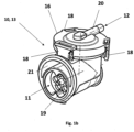
- FIG. 1a shows a schematic view of a gas control device 10 according to the invention for a ventilator 1.
- Respirators 1 usually have an inspiratory branch, which is intended for the supply of respiratory gas to a patient, and an expiratory branch, which is intended for the removal of respiratory gas exhaled by the patient serves.
- the gas control device (10) can be designed as an electrical and/or pneumatic control unit and set up to allow a pressurized gas stream to pass in a first direction (25) and a blocking the pressurized gas flow in a second direction (26) and blocking and/or at least temporarily enabling a gas flow from the first gas channel (11) to the bypass channel (21), a gas control device (10) being set up to control a gas flow from the first gas channel 11 to the bypass channel (21) to block and / or at least temporarily allow.
- the gas control device 10 is intended for use in a ventilator 1 or as part of a ventilator and has a first gas channel 11 with a first valve (19), the first gas channel (11) and the valve (19) being configured to have a lower to allow pressurized gas flow to pass in a first direction (25) and to block pressurized gas flow in a second direction (26), an orifice (14) branching off from the first gas channel 11 and leading to a bypass channel (21) for the valve (19), with a second valve (15, 16) being set up to block and/or at least temporarily enable a gas flow from the first gas duct (11) to the bypass duct (21), with a switching device (13) the second valve (15, 16) is set up to control, block and/or at least temporarily allow a gas flow from the first gas channel 11 to the bypass channel (21).
- the switching device here includes, for example, the valve block 13 with the first 19 and second valve, the first 11 and second gas path and the bypass 14, 21.
- the switching device 13 also includes the pneumatic or electronic control for the components of the valve block.
- the gas flow passes through the open check valve (19).
- the breathing gas flows in a second direction (26) through the breathing tube, the connection piece (28) and the first gas channel (11) to the non-return valve (19).
- This is a pneumatically operated non-return valve (19) which is actuated by the force of the pressurized expiratory gas flow in the second direction (26) and so cannot pass the non-return valve (19). Since the opening (14) communicating with the first gas channel (11), the pressurized expiration gas flow, in the second direction (26), also propagates into the orifice and reaches the valve (15, 16). If the switching device (13) opens the valve (15,16), the pressurized expiratory gas flow continues along the opening and the bypass channel (21) into the first gas channel and from there at least partially into the environment.
- the valve (15, 16) can be designed as a pneumatic valve.
- a seal (15) of the valve can close or open the gas-conducting connection between opening 14 and the surrounding channel.
- the control impulse for the seal (15) of the valve comes from a second gas channel (12) which directs a pneumatic control pressure to the surface of the seal 15. When the control pressure is applied to the seal, it seals against the edge 22 of the opening 14 and thus prevents gas flow from the opening into the bypass channel.
- the second gas channel can be from the breathing tube or. the gas channel (11) are fed pneumatically. Another compressed gas source, such as a control fan, is also conceivable.
- the switching device 13 opens or closes the pneumatic connection between the second gas channel 12 and the breathing tube or the gas channel (11), at least temporarily.
- the valve (15, 16) can be designed as a switching valve. In this case, activation of the valve, by the switching device 13, opens or closes the flow of gas from the opening 14 into the bypass channel. In this case, a second gas channel is unnecessary.
- Respirators generally have an inspiratory branch, which is provided for supplying respiratory gas to a patient, and an expiratory branch, which is used to discharge respiratory gas exhaled by the patient.
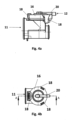
- Figure 1b shows a schematic view of an inventive
- Gas control device 10 for a ventilator for a ventilator.
- the gas control device (10) is only partially shown here, namely as a switching device 13 or as a valve block and comprises a first gas channel (11) with a first valve (19), the first gas channel (11) and the valve (19) being configured as a pressurized gas stream in a first direction (25) and to block a pressurized gas flow in a second direction (26), an opening (14) branching off from the first gas channel 11 and to a bypass channel (21) for the valve (19), leads, and a second valve (15, 16) to open or close the bypass channel (21).
- the gas control device 10 is intended for use in a ventilator and has a first gas channel 11 (inspiratory branch) which guides a gas flow in the direction of a patient.
- the first gas channel 11 includes a check valve 19 and a - not shown - opening with a - not shown- seal.
- the opening and the seal are in the figure 1 covered by a cap 16.
- the non-return valve 19 prevents a recirculation of a breathing gas/gas stream coming from the patient and contaminated by exhalation.
- the gas control device 10 has a second gas channel 12, which leads a gas flow to the opening—not shown.
- the second gas channel 12 is connected via a connection 20 to the closure cap 16 which is clipped onto the opening of the first gas channel.
- the second gas channel 12 runs via the connection 20 to the closure cap 16 and is controlled by a switching device--not shown--.
- a gas stream can flow through the second gas channel 12 .
- the switching device releases the second gas channel 12 for a gas flow or a gas pressure or a gas flow volume.
- the second gas channel 12 is released, so that the gas flow or pressure can be guided via the connection 20 to the seal—not shown—inside the closure cap 16 .
- the gas flow/pressure of the second gas channel 12 presses the seal completely onto the opening and the opening is thus closed.
- an inspiratory gas flow from the first gas channel 11, which is to be routed to the patient is prevented from escaping via the opening into the bypass channel 21. This is not necessary in this case because the expiratory branch is free of blockages, so that the patient's expired breathing gas can be delivered via the expiratory branch.
- the switching device blocks the second gas duct 12.
- the gas flow in the second gas duct 12, which acts on the seal comes to a standstill through the blocked gas duct 12, as a result of which the gas flow in the first gas duct 11 closes the seal, which rests on the opening, so that the gas flow of the first gas channel is guided around the non-return valve via a bypass channel 21 .
- the gas flow or pressure of the first gas channel 11 is greater than the gas flow or pressure of the second gas channel 12, as a result of which the gas flow of the first gas channel 11 can lift the seal that rests on the opening.
- the seal is dimensioned and designed in such a way that the gas flow of the first gas channel 11 can lift it when the gas channel 12 is blocked. Lifting means that the seal is held at its peripheral edge by the closure cap 16 on the edge of the bypass channel 21 and is pushed up towards the center of the circular seal by the gas flow of the first gas channel 11 .
- the weight of the seal is proportioned in such a way that when the gas flow of the second gas channel 12 decreases, it automatically deposits the seal on the opening.
- the patient can therefore exhale even if the expiratory branch is blocked/disturbed.
- the switching device blocks the second gas channel or does not apply any pressure to the seal.
- the switching valve is set up to permanently allow gas to flow out.
- the switching device is set up to switch according to the time-controlled expiration of the ventilator.
- the switching device set up to block the second gas channel 12 when the ventilator is switched to an expiration. This ensures expiration of a patient since the opening of the gas control device is open during expiration and backflowing gas can escape via the opening.
- the switching device activates the second gas channel 12, as a result of which a gas flow can flow into the second gas channel 12 and a pressure is applied thereto.
- the gas flow in the second gas channel 12 seals the seal on the opening, preventing inspiratory gas from escaping through the opening during normal operation
- the closure cap 16 comprises three extensions 18 by means of which the closure cap 16 can be clipped onto the opening of the first gas channel 11 .
- a connection 20 is formed on the closure cap, with which the second gas channel 12 can be connected.
- the connection 20 is arranged centrally on the closure cap 16 so that the gas flow/pressure can be applied centrally and evenly to the seal via the connection 20 and the closure cap 16 .
- the one in the Figure 1b The gas control device 10 shown is thus set up during normal operation to guide the gas flow in the first gas channel 11 through the non-return valve 19 to the patient. During normal operation of the expiratory branch, the opening of the first gas channel 11 is closed and the non-return valve 19 continues to function. If the check valve 19 is blocked/faulty, the gas control device 10 bypasses the check valve 19.
- the - not shown - switching device of the gas control device 10 is triggered by the time-controlled switching of the ventilator between inspiration and expiration.
- the switching device blocks the second gas channel 12 as soon as the ventilator switches to expiration.
- switching can be time-delayed.
- the switching device releases the second gas channel 12 when the ventilator switches to inspiration.
- bypass channel 21 is also shown.
- the bypass passage 21 extends from the orifice and allows the flow of gas exiting the orifice to bypass the check valve 19 .
- the bypass passage 21 is formed circumferentially around the opening and narrows as it progresses to a passage extending in a direction parallel to the first gas passage.
- the bypass duct 21 can then again open into the first gas duct or, as a separate branch, can discharge the gas flow that has passed the check valve.
- the bypass channel has an edge on which the seal can be sealed by the closure cap 16 .
- the edge of the bypass channel 21 can have a prominence behind which an edge of the seal can engage. The edge of the bypass channel 21 prevents the seal from slipping.
- figure 2 shows a schematic exploded view of in figure 1 shown gas control device 10.
- the first and the second gas channel 11, 12, the check valve 19 and the opening 14 with the seal 15 are shown.
- connection 20 The closure cap 16 with the connection 20 is also shown.
- the central arrangement of the connection 20 is shown, with one end of the connection 20 extending outwards and being able to be connected to the second gas channel 12 .
- Edge 22 is designed as an elevation and serves as a shelf for weight 17, which is integrated into seal 15.
- the seal 15 is made of an elastomeric material, preferably a silicone with a hardness of between 15 and 25 Shore A, in particular between 18 and 22 Shore A.
- the seal 15 is circular and has a boundary 23 .
- the border 23 can be designed as a reinforced structure or as a functional emphasis.
- the boundary 23 is set up to rest on an edge 24 of the bypass channel 21 .
- the seal 15 can have a thinner material thickness between the boundary 23 of the seal 15 and the weight 17 than in the area of the edge 24 of the bypass channel 21 and the area of the seal 15 in which the weight 17 is arranged, mostly integrally.
- the seal 15 between the edge 24 of the bypass channel 21 and the weight 17 has a curved structure, which can additionally prevent the seal 15 from being displaced on the opening 14 .
- the seal 15 between the edge 24 of the bypass channel 21 and the weight 17 can have a different structure or can be designed without a structure.
- the weight 17 of the seal 15 is in the form of a washer.
- the weight 17 is made of a metal and is integrally formed in the gasket 17 .
- the weight 17 stabilizes the seal 15 on the opening 14.
- the seal 15 When the closure cap 16 is placed on the opening 14, the seal 15 is pressed against the edge of the bypass channel 21 in the region of the boundary 23 of the seal 15 and held.
- the sealing cap 16 seals the seal 15 from the outside and holds the seal 15 in its position within the sealing cap 16.
- the seal 15 is thus pressed/held within the gas control device 10 by the clipped-on sealing cap 16 on the edge 24 of the bypass channel 21.
- the seal 15 is clamped/sealed between the edge 24 of the bypass channel 21 and the closure cap 16 via the reinforced border 23 formed all around.
- Areas of the seal 15 that differ from the boundary 23 are formed without contact with the closure cap 16 . These areas can also be referred to as impingement areas, since when the second gas channel 12 is released by the switching device, these areas of the seal 15 are subjected to a gas flow/pressure.
- the seal 15 is held in a resting state (without gas flows) on the opening 14 by the weight and its structure. If the switching device is set up to release the second gas duct 12 , the pressure areas of the seal 15 are also subjected to a gas flow/pressure, as a result of which the seal 15 is sealed off from the opening 14 .
- the switching device is set up to block the second gas channel 12, the pressure areas of the seal 15 are not subjected to a gas flow, so that the gas flow of the first gas channel 11 is sufficient to lift the seal in the area of the pressure areas and to direct the gas flow into the bypass channel 21 lead.
- Cap 16 shown includes extensions 18 that form barbs. When the closure cap 16 is clipped on, the barbs engage in recesses which are formed on the outside of the gas control device 10 . In further embodiments, further closure options are conceivable, for example latching in the form of a bayonet closure. Furthermore, in the figure 2 the check valve 19 and the bypass channel 21 are shown.
- FIG 3 shows a longitudinal section through the figures 1 and 2 shown.
- Gas control device 10 Shown is the first gas channel 11 with the check valve 19, the opening 14 and the seal 15 as well as the second gas channel 12.
- the closure cap 16 with the connection 20 and the bypass channel 21 are also shown.
- An inspiratory gas flow can be conveyed to the patient via the first gas channel 11 .
- the check valve 19 prevents exhaled gas from flowing back into the ventilator via the first gas channel 11 .
- the bypass channel 21 which extends from the opening 14 is also shown.
- the bypass channel 21 is formed as a peripheral channel around the opening 14 and extends in its further course to a channel in a direction parallel to the first gas channel 11 extends. Due to the circumferential arrangement of the bypass channel, a large quantity of exhaled gas can be discharged past the non-return valve 19 and via the opening 14 at the same time.
- the bypass channel 21 can open into the inspiratory branch or be designed as a separate expiratory branch.
- the seal 15 is circular and has a weight 17 at its center.
- the weight 17 is ring-shaped/washer-shaped. In its shape-related recess, the weight 17 has a conical configuration of the seal 15 which extends in the direction of the first gas channel 11 .
- the conical configuration offers the advantage that the seal 15 is secured against slipping in its position on the opening 14 .
- the configuration of the seal 15 can have a different geometric shape suitable for holding the seal 15 in position.
- the weight 17 is integrated into the seal 15 .
- the seal 15 has a greater material thickness in the area of the weight 17 . On the one hand, this offers the advantage that the weight 17 can be integrated into the seal 15 and, on the other hand, the greater material thickness produces an additional weight 17 that holds the seal 15 in its position.
- the weight 17 can also be applied to the seal 15 .
- the closure cap 16 shown is arranged on the opening 14, with the closure cap 16 pressing the seal 15 onto the edge of the bypass channel 21 in the area of the boundary 23, while the seal 15 is arranged without contact with the closure cap 16 in the impact areas.
- Figure 4a shows a side view of in the Figures 1 to 3 shown gas control device 10. Shown is the first gas channel 11 and the cap 16 with the extensions 18 and the connection 20 for the - not shown - second gas channel.
- the inlet side of the first gas channel 11 is larger than the outlet side.
- the input side also includes the bypass channel 21 narrowed to form a channel.
- the input side of the first gas channel 11 therefore includes both the first gas channel 11 oriented in the inspiration flow direction Gas channel 11 and the bypass channel 21, which is oriented counter to the inspiration flow direction.
- Figure 4b shows a plan view of the closure cap 16 according to the invention in FIGS Figures 1 to 4b shown gas control device 10 according to the invention.
- the cap 16 is on the - clipped opening of the first gas channel - not shown.
- the seal in the area of the weight (not shown) of the closure cap 16 is pushed onto a - in figure 3 shown - elevation 22 of the opening pressed and sealed.
- the closure cap 16 has a connection 20 for the second gas channel 12 (not shown).
- the gas stream of the second gas channel 12 (not shown) can be applied to the seal (not shown) via the connection 20 in order to close the opening (not shown).
- the closure cap 16 also includes the extensions 18 which mostly form barbs and are set up to engage in recesses in the area of the opening.
- the closure cap 16 can have further extensions 18 or can be fastened to the opening via similar latching elements.
- Figure 4c shows a plan view of the check valve 19 in FIGS Figures 1 to 4b shown gas control device 10 according to the invention.
- the check valve 19 is viewed from the direction of the inflowing gas flow, in the inspiration flow direction.
- the bypass channel 21 is also shown, via which the gas flow can be guided around the non-return valve 19 in the event of a blockage/fault in the expiratory branch of the ventilator.
- closure cap 16 is also shown in a side view with the extensions 18 by means of which the closure cap 16 can be clipped onto the opening (not shown).
Description
Die vorliegende Erfindung betrifft eine Gassteuerungsvorrichtung für ein Beatmungsgerät umfassend einen ersten Gaskanal mit einem Rückschlagventil, einen zweiten Gaskanal und eine Schalteinrichtung. Die Gassteuerungsvorrichtung kann in dem Beatmungsgerät angeordnet sein oder dem Beatmungsgerät zugeordnet sein.The present invention relates to a gas control device for a ventilator comprising a first gas channel with a check valve, a second gas channel and a switching device. The gas control device may be located in the ventilator or associated with the ventilator.
Beatmungsgeräte werden für die Therapie respiratorischer Störungen eingesetzt, dabei können die Beatmungsgeräte in der nicht-invasiven und invasiven Beatmung, sowohl innerklinisch als auch außerklinisch, verwendet werden.Ventilators are used for the therapy of respiratory disorders. The ventilators can be used in non-invasive and invasive ventilation, both in-hospital and out-of-hospital.
Bei einer Beatmung eines Patienten kann in der Regel ein Beatmungsgerät mit einem inspiratorischen Zweig für den Atemgasfluss und optional mit einem Zweig für den exspiratorischen Atemgasfluss eingesetzt werden. Der Zweig für den exspiratorischen Atemgasfluss ermöglicht die Ausatmung/Exspiration eines Atemgases durch den Patienten, während der Zweig für den inspiratorischen Atemgasfluss den Patienten mit Atemgas versorgt.When ventilating a patient, a ventilator with an inspiratory branch for the respiratory gas flow and optionally with a branch for the expiratory respiratory gas flow can usually be used. The expiratory flow branch allows the patient to exhale/exhale a breathing gas, while the inspiratory flow branch supplies breathing gas to the patient.
Bei den im Stand der Technik bekannten Beatmungsgeräten kann es zu Blockaden/Störungen im exspiratorischen Zweig des Beatmungsgerätes kommen.With the ventilators known in the prior art, blockages/disorders can occur in the expiratory branch of the ventilator.
Wenn der inspiratorische Zweig des Beatmungsgerätes ein Rückschlagventil umfasst, ist eine Rückführung ausgeatmeten Atemgases in das Beatmungsgerät nicht möglich. Der Patient ist dann an einer Ausatmung gehindert.If the inspiratory branch of the ventilator includes a non-return valve, it is not possible to recycle exhaled respiratory gas into the ventilator. The patient is then prevented from exhaling.
Es ist daher Aufgabe der vorliegenden Erfindung, eine Vorrichtung zur Verfügung zu stellen, die eine Exspiration von Atemgas auch bei einer Störung/Blockade eines, insbesondere exspiratorischen, Zweiges eines Beatmungsgerätes sicherstellt.It is therefore the object of the present invention to provide a device which ensures expiration of breathing gas even in the event of a malfunction/blockage of one, in particular expiratory, branch of a ventilator.
Es ist auch Aufgabe der vorliegenden Erfindung, eine Vorrichtung zur Verfügung zu stellen, die einen bedarfsweise aktivierbaren Gaskanal bereitstellt.It is also the object of the present invention to provide a device that provides a gas channel that can be activated as required.
Diese Aufgabe wird durch eine Gassteuerungsvorrichtung gemäß dem Anspruch 1 gelöst. Weiterbildungen und vorteilhafte Ausgestaltungen sind Gegenstand der Unteransprüche. Weitere Vorteile und Merkmale ergeben sich aus der allgemeinen Beschreibung und der Beschreibung der Ausführungsbeispiele.This object is solved by a gas control device according to claim 1. Further developments and advantageous configurations are the subject matter of the dependent claims. Further advantages and features emerge from the general description and the description of the exemplary embodiments.
Die vorliegende Erfindung betrifft eine Gassteuerungsvorrichtung für ein Beatmungsgerät umfassend einen ersten Gaskanal mit einem ersten Ventil, wobei der erste Gaskanal und das Ventil eingerichtet sind, einen unter Druck stehenden Gasstrom in einer ersten Richtung passieren zu lassen und einen unter Druck stehenden Gasstrom in einer zweiten Richtung zu sperren, wobei eine Öffnung von dem ersten Gaskanal abzweigt und zu einem Umgehungskanal, für das Ventil, führt, wobei ein zweites Ventil eingerichtet ist, einen Gasstrom vom dem ersten Gaskanal zu dem Umgehungskanal zu sperren und/oder zumindest zeitweise zu ermöglichen, wobei eine Schalteinrichtung eingerichtet ist das zweite Ventil zu steuern, einen Gasstrom vom dem ersten Gaskanal zu dem Umgehungskanal zu sperren und/oder zumindest zeitweise zu ermöglichen.The present invention relates to a gas control device for a ventilator comprising a first gas channel with a first valve, the first gas channel and the valve being set up to allow a pressurized gas flow to pass in a first direction and a pressurized gas flow in a second direction to block, wherein an opening branches off from the first gas channel and leads to a bypass channel for the valve, wherein a second valve is set up to block and/or at least temporarily enable a gas flow from the first gas channel to the bypass channel, wherein a Switching device is set up to control the second valve, to block a gas flow from the first gas duct to the bypass duct and/or to at least temporarily allow it.
Die vorliegende Erfindung betrifft auch eine Gassteuerungsvorrichtung umfassend einen ersten Gaskanal mit einem ersten Ventil, wobei der erste Gaskanal und das Ventil eingerichtet sind, einen unter Druck stehenden Gasstrom in einer ersten Richtung passieren zu lassen und einen unter Druck stehenden Gasstrom in einer zweiten Richtung zu sperren, wobei eine Öffnung von dem ersten Gaskanal abzweigt und zu einem Umgehungskanal, für das Ventil, führt, wobei ein zweites Ventil eingerichtet ist, einen Gasstrom vom dem ersten Gaskanal zu dem Umgehungskanal zu sperren und/oder zumindest zeitweise zu ermöglichen, wobei eine Schalteinrichtung eingerichtet ist das zweite Ventil zu steuern, einen Gasstrom vom dem ersten Gaskanal zu dem Umgehungskanal zu sperren und/oder zumindest zeitweise zu ermöglichen.The present invention also relates to a gas control device comprising a first gas channel with a first valve, the first gas channel and the valve being arranged to allow a pressurized gas flow to pass in a first direction and to block a pressurized gas flow in a second direction , wherein an opening branches off from the first gas duct and leads to a bypass duct for the valve, wherein a second valve is set up to block and/or at least temporarily enable a gas flow from the first gas duct to the bypass duct, a switching device being set up the second valve is to be controlled to block and/or at least temporarily allow a gas flow from the first gas channel to the bypass channel.
Die vorliegende Erfindung ist auch dadurch gekennzeichnet, dass die zweite Richtung entgegengesetzt zur ersten Richtung ist.The present invention is also characterized in that the second direction is opposite to the first direction.
Die vorliegende Erfindung ist auch dadurch gekennzeichnet, dass das erste Ventil ein pneumatisch betätigtes Rückschlagventil ist, welches durch die Kraft des unter Druck stehenden Gasstroms in der zweiten Richtung betätigt wird und somit der Gasstrom das Rückschlagventil in einer zweiten Richtung nicht passieren kann.The present invention is also characterized in that the first valve is a pneumatically actuated check valve which is actuated by the force of the pressurized gas flow in the second direction and thus the gas flow cannot pass the check valve in a second direction.
Die vorliegende Erfindung ist auch dadurch gekennzeichnet, dass der Gasstrom der zweiten Richtung, Atemgas der Exspiration ist und der Gasstrom der ersten Richtung Atemgas der Inspiration ist.The present invention is also characterized in that the gas flow of the second direction is respiratory gas of expiration and the gas flow of the first direction is respiratory gas of inspiration.
Die vorliegende Erfindung ist auch dadurch gekennzeichnet, dass eine Atemgasquelle Atemgas aus der Umgebung ansaugt und entlang dem ersten Gaskanal für die Inspiration in der ersten Richtung zu dem Schlauchstutzen und dem Beatmungsschlauch befördert, wobei der Gasstrom das geöffnete Rückschlagventil passiert.The present invention is also characterized in that a respiratory gas source draws respiratory gas from the environment and conveys it along the first gas channel for inspiration in the first direction to the hose connector and the breathing tube, the gas flow passing through the opened check valve.
Die vorliegende Erfindung ist auch dadurch gekennzeichnet, dass die Schalteinrichtung das Ventil öffnet und so der unter Druck stehende Gasstrom der Exspiration durch die Öffnung und durch den Umgehungskanal zumindest teilweise in die Umgebung gelangt.The present invention is also characterized in that the switching device opens the valve and the pressurized gas flow of the expiration thus at least partially escapes through the opening and through the bypass channel into the environment.
Die vorliegende Erfindung ist auch dadurch gekennzeichnet, dass das Ventil als pneumatisches Ventil ausgeführt ist, wobei eine Dichtung des Ventils die gasleitende Verbindung zwischen Öffnung und Umgebungskanal verschließt oder öffnet und wobei ein zweiter Gaskanal eingerichtet ist einen pneumatischen Steuerdruck auf die Oberfläche der Dichtung zu leiten.The present invention is also characterized in that the valve is designed as a pneumatic valve, with a seal of the valve closing or opening the gas-conducting connection between the opening and the surrounding channel, and with a second gas channel being set up to direct a pneumatic control pressure to the surface of the seal.
Die vorliegende Erfindung ist auch dadurch gekennzeichnet, dass die mit dem Steuerdruck beaufschlagte Dichtung eingerichtet ist, sich dichtend an den Rand der Öffnung anzulegen und so einen Gasstrom von der Öffnung in den Umgehungskanal zu verhindern.The present invention is also characterized in that the seal subjected to the control pressure is arranged to sealingly abut the edge of the opening and thus prevent gas flow from the opening into the bypass duct.
Die vorliegende Erfindung ist auch dadurch gekennzeichnet, dass der zweite Gaskanal mit dem Beatmungsschlauch oder dem Gaskanal pneumatisch verbunden ist und die Schalteinrichtung die pneumatische Verbindung zumindest zeitweise öffnet oder verschließt.The present invention is also characterized in that the second gas channel is pneumatically connected to the breathing tube or the gas channel and the switching device at least temporarily opens or closes the pneumatic connection.
Die vorliegende Erfindung betrifft auch eine Gassteuerungsvorrichtung für ein Beatmungsgerät umfassend einen ersten Gaskanal mit einem Rückschlagventil, einen zweiten Gaskanal und eine Schalteinrichtung, wobei der erste Gaskanal eine Öffnung zum Ausströmen von Gas mit einer Dichtung und einer Verschlusskappe aufweist.The present invention also relates to a gas control device for a ventilator comprising a first gas channel with a check valve, a second gas channel and a switching device, the first gas channel having an opening for outflow of gas with a seal and a closure cap.
Erfindungsgemäß ist die Gassteuerungsvorrichtung eingerichtet, bei einer Blockade/Störung eines exspiratorischen Zweiges des Beatmungsgerätes den Gasstrom des ersten Gaskanals an dem Rückschlagventil vorbeizuführen. Dadurch wird bei einer Blockade/Störung des exspiratorischen Zweiges eine Ausatmung des Patienten sichergestellt. Beispielsweise ist der erste Gaskanal mit dem zweiten Gaskanal verbunden. Eine getrennte Ausbildung des ersten Gaskanals und des zweiten Gaskanals, wobei der zweite Gaskanal durch einen separaten Gaskanal gespeist wird, ist in einer alternativen Ausgestaltung denkbar. Auch ist es denkbar, die erfindungsgemäße Gassteuerungsvorrichtung ebenfalls bei einer Blockade/Störung in einem inspiratorischen Zweig des Beatmungsgerätes einzusetzen. In einem solchen Fall könnte die Gassteuerungsvorrichtung eingesetzt werden, um eine Inspiration eines Patienten bei einer Blockade/Störung in dem inspiratorischen Zweig des Beatmungsgerätes sicherzustellen.According to the invention, the gas control device is set up to direct the gas flow of the first gas channel past the check valve in the event of a blockage/fault in an expiratory branch of the ventilator. This ensures that the patient can exhale in the event of a blockage/disorder in the expiratory branch. For example, the first gas channel is connected to the second gas channel. A separate design of the first gas channel and the second gas channel, with the second gas channel being fed by a separate gas channel, is conceivable in an alternative embodiment. It is also conceivable to use the gas control device according to the invention in the event of a blockage/malfunction in an inspiratory branch of the ventilator. In such a case, the gas control device could be used to ensure inspiration of a patient in the event of a blockage/fault in the inspiratory branch of the ventilator.
Die Gassteuerungsvorrichtung ist eingerichtet, bei einer Blockade bzw. Störung des exspiratorischen Zweiges den zweiten Gaskanal derart zu steuern, dass der Gasstrom des ersten Gaskanals über die Öffnung ausströmt bzw. an dem Rückschlagventil über einen Umgehungskanal vorbeiströmt. Der Gasstrom des ersten Gaskanals setzt sich dabei in der Regel aus einem Einatemgas und/oder einem Ausatemgas zusammen. Insbesondere bei einer Blockade/Störung des exspiratorischen Zweiges kann das Ausatemgas eines Patienten über den inspiratorischen Zweig/den ersten Gaskanal, bis hin zu dem Rückschlagventil zurückgeführt werden. Daher ist die Öffnung des ersten Gaskanals vorteilhafterweise im Bereich des Rückschlagventils in Inspirationsflussrichtung dem Rückschlagventil nachgeschaltet angeordnet.The gas control device is set up to control the second gas channel in the event of a blockage or disruption of the expiratory branch in such a way that the gas flow of the first gas channel flows out via the opening or flows past the check valve via a bypass channel. The gas flow of the first gas channel is usually made up of an inhaled gas and/or an exhaled gas. In particular in the event of a blockage/disorder in the expiratory branch, the exhaled gas of a patient can be fed back via the inspiratory branch/the first gas channel to the non-return valve. The opening of the first gas channel is therefore advantageously arranged downstream of the check valve in the area of the check valve in the inspiration flow direction.
Die Gassteuerungsvorrichtung ist eingerichtet, den Druck in dem zweiten Gaskanal zu steuern. Zu steuern kann dabei bedeuten, dass die Schalteinrichtung eingerichtet sein kann, den zweiten Gaskanal freizugeben oder zu sperren. In einer alternativen Ausführungsform kann die Schalteinrichtung kontinuierlich stufenlos steuerbar sein. Basierend auf der Steuerung des Gasstroms des zweiten Gaskanals, insbesondere der Freigabe oder Sperrung des zweiten Gaskanals, kann der Gasstrom des ersten Gaskanals (das Ausatemgas/ der AusatemGasstrom) an dem Rückschlagventil vorbeigeführt werden. Der Gasstrom des ersten Gaskanals wird über einen Umgehungskanal an dem Rückschlagventil vorbeigeführt. Der in den Umgehungskanal umgelenkte Gasstrom kann erneut dem ersten Gaskanal, vorteilhafterweise in einem Bereich der in Inspirationsflussrichtung des Gasstroms dem Rückschlagventil vorgeschaltet liegt, zugeführt werden oder über den Umgehungskanal oder einen separaten Zweig, der als inspiratorischer oder exspiratorischer Zweig eingerichtet sein kann, abgeführt werden.The gas control device is set up to control the pressure in the second gas channel. In this context, controlling can mean that the switching device can be set up to enable or block the second gas channel. In an alternative embodiment, the switching device can be continuously steplessly controlled. Based on the control of the gas flow of the second gas channel, in particular the release or blocking of the second gas channel, the gas flow of the first gas channel (the exhaled gas/the exhaled gas flow) can be guided past the check valve. The gas flow of the first gas channel is routed past the check valve via a bypass channel. The gas flow diverted into the bypass channel can again be fed to the first gas channel, advantageously in an area upstream of the check valve in the inspiration flow direction of the gas flow, or be discharged via the bypass channel or a separate branch, which can be set up as an inspiratory or expiratory branch.
Die Gassteuerungsvorrichtung kann dabei eingerichtet sein, basierend auf einem erfassten Volumen, einem erfassten Durchfluss oder einem erfassten Druck eines Gasstroms steuerbar zu sein.The gas control device can be set up to be controllable based on a detected volume, a detected flow rate or a detected pressure of a gas flow.
insbesondere kann die Gassteuerungsvorrichtung mindestens einen Sensor umfassen, wobei die Schalteinrichtung eingerichtet sein kann, basierend auf einem durch den mindestens einen Sensor erfassten Parameter steuerbar zu sein.In particular, the gas control device can include at least one sensor, wherein the switching device can be set up to be controllable based on a parameter detected by the at least one sensor.
Der mindestens eine Sensor der Gassteuerungsvorrichtung beispielsweise als Teil der Schalteinrichtung kann eingerichtet sein, mindestens einen Atmungsparameter, Atemgasparameter und/oder einen anderen Parameter aus Ausgangssignalen zu erfassen. Dabei können ein oder mehrere erfasste Parameter eine Funktion bilden, die sich beispielsweise auf Messungen von einem oder mehreren der folgenden beziehen: (Spitzen-) Durchfluss, Durchflussrate, (Tidal-) Volumen, Druck, Temperatur, Feuchtigkeit, Geschwindigkeit, Beschleunigung, Gaszusammensetzung (z. B. Konzentration(en) von einem oder mehreren Bestandteilen), thermische Energiedissipation, (beabsichtigte) Gasleckage und/oder andere Messungen in Bezug auf den Atemgasfluss.The at least one sensor of the gas control device, for example as part of the switching device, can be set up to detect at least one respiration parameter, respiratory gas parameter and/or another parameter from output signals. One or more detected parameters can form a function relating, for example, to measurements of one or more of the following: (peak) flow, flow rate, (tidal) volume, pressure, temperature, humidity, velocity, acceleration, gas composition ( eg concentration(s) of one or more components), thermal energy dissipation, (intended) gas leakage and/or other measurements related to the respiratory gas flow.
Atmungsparameter können beispielsweise aus Gasparametern und/oder anderen Ausgangssignalen abgeleitet werden, wobei ein oder mehrere Atmungsparameter eine oder mehrere der folgenden sein können: Atmungsfrequenz, Atmungsdauer, Einatmungszeit oder -dauer, Ausatmungszeit oder -periode, Form der Atmungsflusskurve, Übergangszeit von der Einatmung zur Ausatmung und/oder umgekehrt, Übergangszeit von der (Spitze-) Inhalationsflussrate zu (Spitzen-) Exspirationsflussrate und/oder umgekehrt, Atmungsdruckkurvenform, maximaler proximaler Druckabfall (pro Atmungszyklus und/oder Phase), Anteil an eingeatmetem Sauerstoff und/oder andere Atmungsparameter.Respiratory parameters can be derived, for example, from gas parameters and/or other output signals, where one or more respiratory parameters can be one or more of the following: respiratory rate, respiratory duration, inspiration time or duration, expiration time or period, shape of the respiratory flow curve, transition time from the Inspiration to exhalation and/or vice versa, transition time from inspiratory (peak) flow rate to expiratory (peak) flow rate and/or vice versa, respiratory pressure waveform, maximum proximal pressure drop (per respiratory cycle and/or phase), fraction of inspired oxygen and/or other respiratory parameters .
Die erfindungsgemäße Gassteuerungsvorrichtung ermöglicht es einem Patienten auch bei einer Blockade/Störung des exspiratorischen Zweiges des Beatmungsgerätes ausatmen zu können.The gas control device according to the invention enables a patient to be able to exhale even if the expiratory branch of the ventilator is blocked/disrupted.
Die Gassteuerungsvorrichtung beispielsweise über die Schalteinrichtung ist eingerichtet, den Gasstrom des zweiten Gaskanals zu steuern und eine Vorbeiführung des Gasstroms des ersten Gaskanals um das Rückschlagventil durch die Öffnung zu ermöglichen. Durch die Steuerung des Gasstroms des zweiten Gaskanals kann die Öffnung, auf der die Dichtung aufliegt, die durch den Gasstrom/Druck des zweiten Gaskanals abgedichtet wird, geöffnet werden. Der Gasstrom des ersten Gaskanals kann aus der Öffnung austreten. Bei einer Sperrung des zweiten Gaskanals ändert sich das Druckverhältnis im Bereich der Dichtung, sodass ein Gasdruck des Gasstroms des ersten Gaskanals größer ist als ein Gasdruck des zweiten Gaskanals. In der Regel ist der Gasdruck des gesperrten zweiten Gaskanals gleich null.The gas control device, for example via the switching device, is set up to control the gas flow of the second gas channel and to allow the gas flow of the first gas channel to bypass the check valve through the opening. By controlling the gas flow of the second gas channel, the opening on which the seal rests, which is sealed by the gas flow/pressure of the second gas channel, can be opened. The gas flow of the first gas channel can exit from the opening. When the second gas channel is blocked, the pressure ratio in the area of the seal changes, so that a gas pressure of the gas flow in the first gas channel is greater than a gas pressure in the second gas channel. As a rule, the gas pressure of the blocked second gas channel is equal to zero.
In der Regel ist der Umgehungskanal ringförmig um die Öffnung des ersten Gaskanals ausgebildet. Ringförmig kann auch die Öffnung umschließend bedeuten. Die ringförmige Ausgestaltung bietet den Vorteil, dass Gas in einem Winkel von bis zu 360° aus der Öffnung strömen kann. Dadurch kann eine entsprechend große Menge an exspiratorischem Ausatemgas gleichzeitig über die Öffnung des ersten Gaskanals abgeführt werden. Vorteilhafterweise ist der Umgehungskanal eingerichtet, den über die Öffnung ausgegebenen Gasstrom zu bündeln und in eine Richtung abzuführen.As a rule, the bypass channel is designed in the shape of a ring around the opening of the first gas channel. Ring-shaped can also mean enclosing the opening. The ring-shaped configuration offers the advantage that gas can flow out of the opening at an angle of up to 360°. As a result, a correspondingly large amount of expiratory exhaled gas can be discharged at the same time via the opening of the first gas channel. The bypass channel is advantageously set up to bundle the gas flow discharged via the opening and to discharge it in one direction.
In Ausgestaltung ist die Gassteuerungsvorrichtung beispielsweise über die Schalteinrichtung eingerichtet, den zweiten Gaskanal freizugeben oder zu sperren. Beispielsweise ist die Schalteinrichtung eingerichtet, den zweiten Gaskanal freizugeben, wodurch auf die Dichtung, die auf der Öffnung aufliegt, ein Gasstrom/Druck beaufschlagt werden kann. Durch die Beaufschlagung der Dichtung mit einem Gasstrom/Druck ist die Dichtung auf die Öffnung andrückbar. Die Schalteinrichtung kann auch eingerichtet sein den zweiten Gaskanal zu sperren, sodass kein Gasstrom/Druck auf die Dichtung, die auf der Öffnung aufliegt, beaufschlagt werden kann. In diesem Fall liegt die Dichtung locker auf der Öffnung auf. Bei dieser Ausgestaltung kann ein Gasstrom des ersten Gaskanals durch die lose/locker auf der Öffnung aufliegende Dichtung in einen Umgehungskanal strömen.In one refinement, the gas control device is set up, for example via the switching device, to enable or block the second gas channel. For example, the switching device is set up to release the second gas channel, as a result of which a gas flow/pressure can be applied to the seal that rests on the opening. By subjecting the seal to a gas flow/pressure, the seal is on the opening pressable. The switching device can also be set up to block the second gas channel, so that no gas flow/pressure can be applied to the seal that rests on the opening. In this case, the seal rests loosely on the opening. In this configuration, a gas flow from the first gas channel can flow through the seal lying loosely on the opening into a bypass channel.
Vorteilhafterweise ist die Gassteuerungsvorrichtung beispielsweise über die Schalteinrichtung eingerichtet, den zweiten Gaskanal bei einer Blockade/Störung des exspiratorischen Zweiges zu sperren. Zu sperren bedeutet, dass die Schalteinrichtung keinen Gasstrom/Druck in dem zweiten Gaskanal bereitstellt bzw. diesen verschließt. Durch die Nicht-Beaufschlagung der Dichtung mit einem Gasstrom des zweiten Gaskanals ist der Gasstrom des ersten Gaskanals ausreichend, um die Dichtung anzuheben und den Gasstrom aus dem ersten Gaskanal in den Umgehungskanal zu überführen.The gas control device is advantageously set up, for example via the switching device, to block the second gas channel in the event of a blockage/fault in the expiratory branch. Blocking means that the switching device does not provide any gas flow/pressure in the second gas channel or closes it. Because the seal is not subjected to a gas flow from the second gas channel, the gas flow from the first gas channel is sufficient to lift the seal and transfer the gas flow from the first gas channel into the bypass channel.
Typischerweise ist die Gassteuerungsvorrichtung beispielsweise über die Schalteinrichtung eingerichtet, den zweiten Gaskanal bei einer Verwendung des Beatmungsgerätes in einem Ventilsystem freizugeben, sodass der zweite Gaskanal einen Gasstrom führen kann. Bei der Verwendung in einem Ventilsystem ist/sind der exspiratorische und/oder der inspiratorische Zweig des Beatmungsgerätes störungsfrei ist/sind und die Öffnung der Gassteuerungsvorrichtung wird durch einen Druck des zweiten Gaskanals, der in der Regel als Druckkanal ausgestaltet ist, verschlossen.Typically, the gas control device is set up, for example via the switching device, to release the second gas channel when the ventilator is used in a valve system, so that the second gas channel can conduct a gas flow. When used in a valve system, the expiratory and/or inspiratory branch of the ventilator is/are undisturbed and the opening of the gas control device is closed by a pressure of the second gas channel, which is usually designed as a pressure channel.
Freigeben bedeutet, dass die Gassteuerungsvorrichtung beispielsweise über die Schalteinrichtung den zweiten Gaskanal für das Durchströmen mit einem Gasstrom öffnet und somit die Dichtung, die auf der Öffnung aufliegt, mit einem Gasstrom/Druck beaufschlagt. In der Regel wird der Gasstrom des zweiten Gaskanals mit einem Druck von 1mbar bis 100mbar beaufschlagt. Durch den Druck wird die Dichtung auf die Öffnung gedrückt und abgedichtet.Releasing means that the gas control device opens the second gas channel for a gas stream to flow through, for example via the switching device, and thus applies a gas stream/pressure to the seal that rests on the opening. As a rule, the gas flow of the second gas channel is subjected to a pressure of 1 mbar to 100 mbar. The pressure pushes the seal onto the opening and seals it.
Die Gassteuerungsvorrichtung ist eingerichtet, bei einem Normalbetrieb des Beatmungsgerätes den Gasstrom aus dem ersten Gaskanal mittels des Gasstroms des zweiten Gaskanals, der über einen Anschluss der Verschlusskappe auf die Dichtung der Gassteuerungsvorrichtung geleitet wird, die Dichtung abzudichten.The gas control device is set up, during normal operation of the ventilator, to seal off the gas flow from the first gas channel by means of the gas flow from the second gas channel, which is conducted via a connection of the closure cap onto the seal of the gas control device.
So kann bei einem Normalbetrieb/einer Verwendung in einem Ventilschlauchsystem die Funktion des Rückschlagventils erhalten bleiben.In this way, the function of the non-return valve can be retained during normal operation/use in a valve hose system.
Die Gassteuerungsvorrichtung ist eingerichtet, bei einem störungsfreien Betriebszustand des Beatmungsgerätes beispielsweise bei einem störungsfreien exspiratorischen Zweig einen Druck über den zweiten Gaskanal auf die Dichtmembran aufzubringen und die Öffnung der Gassteuerungsvorrichtung dadurch zu verschließen.The gas control device is set up to apply pressure via the second gas channel to the sealing membrane when the ventilator is in a fault-free operating state, for example with a fault-free expiratory branch, and thereby to close the opening of the gas control device.
Die Gassteuerungsvorrichtung ist eingerichtet, bei einer Blockade/Störung des exspiratorischen Zweiges den zweiten Gaskanal zu sperren. Dadurch liegt kein Druck auf der Dichtmembran auf und die Öffnung ist durch einen Gasdruck des Gasstroms des ersten Gaskanals öffnenbar. Der Gasstrom, der über die Öffnung austritt, kann erneut dem ersten Gaskanal zugeführt werden oder über einen separaten Zweig abführbar sein.The gas control device is set up to shut off the second gas channel in the event of a blockage/fault in the expiratory branch. As a result, there is no pressure on the sealing membrane and the opening can be opened by a gas pressure of the gas flow of the first gas channel. The gas stream that exits via the opening can be fed back to the first gas channel or can be discharged via a separate branch.
In einer Ausgestaltung kann die Schalteinrichtung (als Teil der Gassteuerungsvorrichtung) eingerichtet sein, basierend auf einer zeitgesteuerten Schaltung einer Exspiration und/oder einer Inspiration steuerbar zu sein.In one embodiment, the switching device (as part of the gas control device) can be set up to be controllable based on a time-controlled switching of an expiration and/or an inspiration.
In einer alternativen Ausgestaltung kann die Schalteinrichtung (als Teil der Gassteuerungsvorrichtung) eingerichtet sein, basierend auf einem Parameter des ersten Gaskanals steuerbar zu sein. Beispielsweise kann mittels eines Sensors mindestens ein Parameter des Gasstroms in dem ersten Gaskanal erfasst werden. Beispielsweise kann mittels eines Drucksensors ein Druck innerhalb des ersten Gaskanals erfasst werden. Die Schalteinrichtung ist dann eingerichtet in Abhängigkeit des erfassten Drucks des Gasstroms in dem ersten Gaskanal steuerbar zu sein. Beispielsweise kann die Schalteinrichtung in der alternativen Ausgestaltung eingerichtet sein, den zweiten Gaskanal in Abhängigkeit der Erreichung eines vorbestimmten Schwellenwertes freizugeben oder zu sperren. Ein solcher Schwellenwert kann beispielsweise ein Wert sein, der über dem durchschnittlich erfassten Druck im ersten Gaskanal liegt. Bei einer Schwellwertüberschreitung kann die Schalteinrichtung eingerichtet sein, den zweiten Gaskanal zu sperren. Sinkt der Druck im ersten Gaskanal unter den Schwellenwert kann die Schalteinrichtung den zweiten Gaskanal freigeben.In an alternative embodiment, the switching device (as part of the gas control device) can be configured to be controllable based on a parameter of the first gas channel. For example, at least one parameter of the gas flow in the first gas channel can be detected by means of a sensor. For example, a pressure within the first gas channel can be detected by means of a pressure sensor. The switching device is then set up to be controllable as a function of the detected pressure of the gas flow in the first gas channel. For example, in the alternative embodiment, the switching device can be set up to enable or block the second gas channel depending on whether a predetermined threshold value is reached. Such a threshold value can, for example, be a value that is above the average pressure recorded in the first gas channel. If the threshold value is exceeded, the switching device can be set up to block the second gas channel. If the pressure in the first gas channel below the threshold value, the switching device can release the second gas channel.
In einer weiteren alternativen Ausführungsform kann mittels eines Sensors beispielsweise auch die Durchflussrate oder ein Volumen des Gasstroms des ersten Gaskanals erfasst werden. Die Schalteinrichtung kann eingerichtet sein, basierend auf der ermittelten Flussrate oder dem erfassten Volumen des Gasstroms steuerbar zu sein. Auch kann die Schalteinrichtung eingerichtet sein basierend auf weiteren Parametern des Gasstroms des ersten Gaskanals steuerbar zu sein.In a further alternative embodiment, a sensor can also be used, for example, to detect the flow rate or a volume of the gas flow in the first gas channel. The switching device can be set up to be controllable based on the determined flow rate or the detected volume of the gas flow. The switching device can also be set up to be controllable based on further parameters of the gas flow of the first gas channel.
In einer weiteren alternativen Ausführungsform kann die Schalteinrichtung (als Teil der Gassteuerungsvorrichtung) zudem variabel schaltbar eingerichtet sein, wobei die Schalteinrichtung eingerichtet sein kann, einen Druck des Gasstroms in dem zweiten Gaskanal zwischen 0mbar und 1bar, insbesondere zwischen 0mbar und 100mbar stufenlos zu steuern. Die Schalteinrichtung kann auch eingerichtet sein, den Gasstrom/Druck in dem zweiten Gaskanal kontinuierlich über einen vorbestimmten Zeitraum auf einen vorbestimmten Wert zu erhöhen.In a further alternative embodiment, the switching device (as part of the gas control device) can also be set up in a variably switchable manner, wherein the switching device can be set up to continuously control a pressure of the gas flow in the second gas channel between 0 mbar and 1 bar, in particular between 0 mbar and 100 mbar. The switching device can also be set up to increase the gas flow/pressure in the second gas channel continuously over a predetermined period of time to a predetermined value.
Die Dichtung für einen Teil der Gassteuerungsvorrichtung, insbesondere für ein Ventil ist ausgebildet, bei einem gesperrten zweiten Gaskanal einen Durchfluss des Gasstroms des ersten Gaskanals durch die Öffnung zu ermöglichen. Die Dichtung dichtet den Umgehungskanal gegen die Öffnung ab. Die Dichtung weist vorteilhafterweise eine Form auf, die die Dichtung in einem Gasleeren Zustand des ersten und des zweiten Gaskanals auf der Öffnung ablegt und hält. Die Dichtung weist ein Auflageflächenverhältnis zwischen ![]()
![]()
![]()
![]()
In Ausgestaltung ist die Dichtung auf der Öffnung aufliegend angeordnet und umfasst ein Gewicht. Das Gewicht, welches vorzugsweise in die Dichtung integriert ausgebildet ist, unterstützt die Positionierung der Dichtung auf der Öffnung. In der Regel weist die Dichtung in dem Bereich, in dem das Gewicht integral ausgebildet ist, im Vergleich zu den umgebenden Bereichen der Dichtung eine höhere Materialstärke auf. Die Dichtung ist typischerweise kreisförmig ausgebildet. Die Dichtung kann alternativ rechteckig, quadratisch oder oval ausgebildet sein oder eine andere geometrische Form aufweisen. Die Dichtung ist in der Regel korrespondierend zu der Form der Öffnung und/oder zu der Form des die Öffnung umgebenden Umgehungskanals ausgebildet. Zwischen dem Rand des Umgehungskanals und dem Gewicht kann die Dichtung eine Wölbung ausbilden, die in Richtung des ersten Gaskanals weist und einem Verrutschen der Dichtung vorbeugt.In one embodiment, the seal is arranged so that it rests on the opening and includes a weight. The weight, which is preferably formed integrally with the seal, assists in positioning the seal on the opening. As a rule, the seal has a greater material thickness in the area in which the weight is integrally formed compared to the surrounding areas of the seal. The seal is typically circular in shape. Alternatively, the seal can be rectangular, square or oval or have another geometric shape. The seal is generally designed to correspond to the shape of the opening and/or to the shape of the bypass channel surrounding the opening. The seal can form a bulge between the edge of the bypass channel and the weight, which bulge points in the direction of the first gas channel and prevents the seal from slipping.
In einer Weiterbildung der Erfindung ist das Gewicht der Dichtung ringförmig in der Mitte der Dichtung ausgebildet. In der Mitte bedeutet dabei im Zentrum der kreisförmigen Dichtung. In der Regel ist das ringförmige Gewicht unterlegscheibenförmig ausgebildet. Das Gewicht kann jedoch ebenfalls eine rechteckige oder ovale Form aufweisen. Durch die ringförmige Ausgestaltung kann die Dichtung auf einem die Öffnung umlaufend umgebenden Rand der Öffnung abgelegt werden. Die Dichtung kann auch nur bereichsweise auf dem Rand der Öffnung aufliegen. In der Regel ist die Form des Gewichts korrespondierend zur Form der Öffnung bzw. zur Form des Randes der Öffnung ausgebildet. Das Gewicht beschwert die Dichtung, wodurch die Dichtung locker auf dem Rand der Öffnung gehalten wird. Optional kann das Gewicht rechteckig ausgebildet sein oder eine andere geometrische Form aufweisen. Zudem kann das Gewicht in einem anderen Bereich der Dichtung angeordnet sein.In a further development of the invention, the weight of the seal is ring-shaped in the middle of the seal. In the middle means in the center of the circular seal. As a rule, the ring-shaped weight is designed in the form of a washer. However, the weight can also have a rectangular or oval shape. Due to the ring-shaped configuration, the seal can be placed on an edge of the opening that surrounds the opening. The seal can also only partially rest on the edge of the opening. As a rule, the shape of the weight is designed to correspond to the shape of the opening or to the shape of the edge of the opening. The weight weighs down the gasket, which loosely holds the gasket on the rim of the opening. Optionally, the weight can be rectangular or have another geometric shape. In addition, the weight can be arranged in a different area of the seal.
Die Dichtung ist aus einem elastomeren Material ausgebildet und das Gewicht ist aus einem Metall ausgebildet. Die Dichtung ist in der Regel aus einem elastomeren Material mit einer Härte im Bereich zwischen 15 bis 25 Shore A, insbesondere zwischen 18 und 22 Shore A ausgebildet. Beispielsweise ist die Dichtung aus einem Silikon gefertigt. Alternativ kann das Gewicht aus einem anderen Material, beispielsweise einem Hartplastik oder einer Kombination aus Metall und Kunststoff, ausgebildet sein.The seal is formed from an elastomeric material and the weight is formed from a metal. The seal is usually made of an elastomeric material with a hardness in the range between 15 and 25 Shore A, in particular between 18 and 22 Shore A. For example, the seal is made of silicone. Alternatively it can Be weight made of another material, such as a hard plastic or a combination of metal and plastic.
In einer weiteren Weiterbildung der Erfindung weist die Dichtung eine Ausprägung auf, die im Bereich des Gewichts in Richtung des ersten Gaskanals weisend ausgebildet ist. Die Ausprägung kann als kegelförmige Hervorhebung ausgestaltet sein, deren Spitze sich von der Öffnung in den ersten Gaskanal hineinweisend erstreckt. Beispielsweise kann die Ausprägung in der durch die unterlegscheibenförmige Ausgestaltung bedingten Ausnehmung des Gewichts ausgebildet sein. Die Ausprägung unterstützt die Dichtung auf der Öffnung des ersten Gaskanals zu halten. Die Ausprägung kann optional in einer beliebigen Form ausgebildet sein, die die Dichtung in ihrer Position auf der Öffnung hält. In einer alternativen Ausführungsform kann die Dichtung ausprägungsfrei ausgebildet sein.In a further development of the invention, the seal has an expression which is designed to point in the direction of the first gas channel in the area of the weight. The embossment can be designed as a conical prominence, the tip of which extends from the opening pointing into the first gas channel. For example, the embossing can be formed in the recess of the weight caused by the washer-shaped design. The embossing helps to keep the seal on the opening of the first gas channel. The embossment can optionally be formed in any shape that will hold the gasket in place on the opening. In an alternative embodiment, the seal can be designed without any protrusions.
In einer vorteilhaften Weiterbildung der Erfindung ist die Verschlusskappe eingerichtet, auf die Öffnung aufsetzbar zu sein. In der Regel ist die Verschlusskappe auf die Öffnung aufklippbar. Dies bietet den Vorteil, dass die Verschlusskappe beim Aufsetzen auf die Dichtung, die auf der Öffnung aufliegt, diese in ihrer Position nicht verschiebt. Um auf die Öffnung aufklippbar zu sein, weist die Verschlusskappe in der Regel mindestens zwei Fortsätze auf, die typischerweise Widerhaken aufweisen, die in Ausnehmungen, die an einem Außenbereich der Öffnung ausgebildet sind, eingreifen. Alternativ kann die Verschlusskappe der Gassteuerungsvorrichtung mit einem Bajonettverschluss versehen sein. Optional kann die Verschlusskappe mit alternativen Verrastungselementen auf der Öffnung befestigt werden.In an advantageous development of the invention, the closure cap is set up so that it can be placed on the opening. As a rule, the closure cap can be clipped onto the opening. This offers the advantage that the closure cap does not shift its position when it is placed on the seal that rests on the opening. In order to be able to be clipped onto the opening, the closure cap generally has at least two extensions which typically have barbs which engage in recesses which are formed on an outer area of the opening. Alternatively, the cap of the gas control device can be provided with a bayonet lock. Optionally, the cap can be attached to the opening with alternative locking elements.
In einer weiteren vorteilhaften Weiterbildung der Erfindung umfasst die Verschlusskappe einen Anschluss, der mit dem zweiten Gaskanal verbindbar ist. Die Form des Anschlusses ist in der Regel korrespondierend zu der Form des zweiten Gaskanals ausgebildet. Alternativ sind der Anschluss und der Gaskanal durch einen Adapter verbindbar. Der Anschluss ist eingerichtet, den durch die Schalteinrichtung bereitgestellten Gasstrom/Druck des zweiten Gaskanals auf die Dichtung zu führen. Der Anschluss ist in der Regel mit der Verschlusskappe verbunden ausgebildet. Dabei ist der Anschluss typischerweise derart mit der Verschlusskappe verbunden, dass ein Gasstrom vertikal und mittig auf die Dichtung aufbringbar ist. Alternativ kann der Anschluss auch seitlich an der Verschlusskappe angeordnet sein. Der Anschluss, der ebenfalls als Kanal ausgebildet sein kann, weist beispielsweise einen Durchmesser zwischen 0,1mm bis 0,5 mm auf.In a further advantageous development of the invention, the closure cap includes a connection which can be connected to the second gas channel. The shape of the connection is generally designed to correspond to the shape of the second gas channel. Alternatively, the connection and the gas channel can be connected by an adapter. The connection is set up to direct the gas flow/pressure of the second gas channel provided by the switching device to the seal. The connection is usually designed to be connected to the closure cap. In this case, the connection is typically connected to the closure cap in such a way that a gas flow can be applied vertically and centrally to the seal. Alternatively, the connection can also be on the side of the sealing cap be arranged. The connection, which can also be designed as a channel, has a diameter of between 0.1 mm and 0.5 mm, for example.
Erfindungsgemäß ist die Schalteinrichtung (als Teil der Gassteuerungsvorrichtung) eingerichtet, bei einem Normalbetrieb des Beatmungsgerätes den zweiten Gaskanal freizugeben und einen Gasstrom/Druck über den zweiten Gaskanal und den Anschluss auf die Dichtung zu leiten und die Öffnung zu schließen. Bei einem Normalbetrieb des Beatmungsgerätes liegt keine Störung/Blockade eines exspiratorischen oder inspiratorischen Zweiges des Beatmungsgerätes vor. Die Schalteinrichtung ist eingerichtet, den Gasstrom/Druck des zweiten Gaskanals zu steuern. In der Regel wird der Gasstrom in dem zweiten Gaskanal mit einem Gasstrom/Druck von 1mbar bis 1bar, insbesondere zwischen 10mbar und 150mbar, beaufschlagt. Dadurch wird die Dichtung auf die Öffnung des ersten Gaskanals abgedichtet, so dass der Gasstrom des ersten Gaskanals nicht über die Öffnung entweichen kann.According to the invention, the switching device (as part of the gas control device) is set up to release the second gas channel during normal operation of the ventilator and to conduct a gas flow/pressure via the second gas channel and the connection to the seal and to close the opening. When the ventilator is operating normally, there is no malfunction/blockade of an expiratory or inspiratory branch of the ventilator. The switching device is set up to control the gas flow/pressure of the second gas channel. As a rule, the gas flow in the second gas channel is subjected to a gas flow/pressure of 1 mbar to 1 bar, in particular between 10 mbar and 150 mbar. This seals the seal onto the opening of the first gas channel, so that the gas flow from the first gas channel cannot escape via the opening.
Erfindungsgemäß ist die Schalteinrichtung (als Teil der Gassteuerungsvorrichtung) eingerichtet, bei einer Blockade/Störung des exspiratorischen Zweiges den zweiten Gaskanal zu sperren. Durch die Sperrung des zweiten Gaskanals kommt der Gasstrom/Druck des zweiten Gaskanals zum Erliegen. Die Gassteuerungsvorrichtung kann den Gasstrom des ersten Gaskanals über die Öffnung ausleiten. Bei einer Sperrung des zweiten Gaskanals durch die Schalteinrichtung ist der Gasstrom/Druck in dem ersten Gaskanal größer als im zweiten Gaskanal. Dadurch kann der Gasstrom des ersten Gaskanals die Dichtung, die auf der Öffnung aufliegt, anheben und den Gasstrom in den Umgehungskanal führen und das Rückschlagventil umgehen. Die Dichtung wird derart angehoben, dass die Dichtung im Bereich der Begrenzung der Dichtung durch die Verschlusskappe an den Rand des Umgehungskanals angedrückt/gehalten wird. Sobald der zweite Gaskanal gesperrt ist und kein Gasstrom/Druck mehr auf die Dichtung aufgebracht wird, wird das Gewicht der Dichtung durch den Gasstrom des ersten Gaskanals angehoben, sodass die Dichtung, die auf dem Rand der Öffnung aufliegt angehoben wird, wodurch der Gasstrom von dem ersten Gaskanal über die Öffnung in den Umgehungskanal strömen kann.According to the invention, the switching device (as part of the gas control device) is set up to block the second gas channel in the event of a blockage/fault in the expiratory branch. Due to the blocking of the second gas channel, the gas flow/pressure of the second gas channel comes to a standstill. The gas control device can direct the gas flow of the first gas channel via the opening. When the second gas channel is blocked by the switching device, the gas flow/pressure in the first gas channel is greater than in the second gas channel. This allows the gas flow from the first gas passage to lift the seal resting on the opening and guide the gas flow into the bypass passage and bypass the check valve. The seal is lifted in such a way that the seal is pressed/held by the closure cap against the edge of the bypass channel in the area where the seal is delimited. Once the second gas port is blocked and no more gas flow/pressure is being applied to the seal, the weight of the seal is lifted by the gas flow from the first gas port, so the seal resting on the edge of the opening is lifted, causing the gas flow from the first gas channel can flow via the opening into the bypass channel.
Die vorliegende Erfindung umfasst ferner auch eine Dichtung für einen Teil der Gassteuerungsvorrichtung für ein Beatmungsgerät umfassend einen ersten Gaskanal mit einem Rückschlagventil, einen zweiten Gaskanal und eine Schalteinrichtung, wobei der erste Gaskanal eine Öffnung zum Ausströmen von Gas mit einer Dichtung und einer Verschlusskappe aufweist.The present invention also includes a seal for part of the gas control device for a ventilator comprising a first gas channel with a check valve, a second gas channel and a switching device, the first gas channel having an opening for outflow of gas with a seal and a closure cap.
Erfindungsgemäß weist die Dichtung ein Gewicht auf und ist eingerichtet, bei einem gesperrten zweiten Gaskanal einem Gasstrom des ersten Gaskanals einen Durchlass durch die Öffnung zu ermöglichen. Die Dichtung ist in der Regel kreisförmig ausgebildet. Alternativ kann die Dichtung jedoch auch rechteckig ausgebildet sein oder eine andere geometrische Form aufweisen. Typischerweise ist die Dichtung aus einem elastomeren Material, beispielsweise Silikon, ausgebildet. Die Dichtung weist in der Regel eine Härte zwischen 15 bis 25 Shore A, insbesondere zwischen 18 und 22 Shore A auf. Das Gewicht kann in einer alternativen Ausgestaltung in einem anderen Bereich der Dichtung ausgebildet sein.According to the invention, the seal has a weight and is set up to allow a gas flow of the first gas channel to pass through the opening when the second gas channel is blocked. The seal is generally circular in shape. Alternatively, however, the seal can also be rectangular or have a different geometric shape. Typically, the seal is formed from an elastomeric material such as silicone. The seal usually has a hardness of between 15 and 25 Shore A, in particular between 18 and 22 Shore A. In an alternative embodiment, the weight can be formed in a different area of the seal.
In Ausgestaltung weist die Dichtung einen zumindest teilweise umlaufenden Rand auf, der eingerichtet ist, in eine Ausnehmung der Gassteuerungsvorrichtung einzugreifen. Der umlaufende Rand ist vorzugsweise verstärkt ausgebildet und kann eine Ausprägung aufweisen, die in eine Ausnehmung am Rand des Umgehungskanals eingreift. Der umlaufende Rand der Dichtung dient zum einen der Abdichtung und zum anderen der Positionierung der Dichtung auf dem Rand des Umgehungskanals. Er wird durch die Verschlusskappe auf den Rand des Umgehungskanals gedrückt/gehalten/abgedichtet. Der Rand des Umgehungskanals kann eine Hervorhebung aufweisen, die eingerichtet ist, an die Dichtung derart anliegend zu sein, dass eine Kante der Dichtung mit der Hervorhebung in Eingriff kommt.In one refinement, the seal has an at least partially circumferential edge which is set up to engage in a recess in the gas control device. The peripheral edge is preferably reinforced and can have an expression that engages in a recess on the edge of the bypass channel. The peripheral edge of the seal is used on the one hand for sealing and on the other for positioning the seal on the edge of the bypass channel. It is pressed/held/sealed by the sealing cap onto the edge of the bypass channel. The edge of the bypass channel may have a protrusion arranged to abut the gasket such that an edge of the gasket engages the protrusion.
Die vorliegende Erfindung betrifft auch eine Gassteuerungsvorrichtung die Gassteuerungsvorrichtung als elektrische und/oder pneumatische Steuereinheit in einem Beatmungsgerät ausgebildet und eingerichtet ist, einen unter Druck stehenden Gasstrom in einer ersten Richtung passieren zu lassen und einen unter Druck stehenden Gasstrom in einer zweiten Richtung zu sperren und einen Gasstrom vom dem ersten Gaskanal zu dem Umgehungskanal zu sperren und/oder zumindest zeitweise zu ermöglichen, wobei die Gassteuerungsvorrichtung eingerichtet ist, einen Gasstrom von dem ersten Gaskanal zu dem Umgehungskanal zu sperren und/oder zumindest zeitweise zu ermöglichen.The present invention also relates to a gas control device, the gas control device being designed as an electrical and/or pneumatic control unit in a ventilator and set up to allow a pressurized gas flow to pass in a first direction and to block a pressurized gas flow in a second direction and a To block gas flow from the first gas channel to the bypass channel and / or to allow at least temporarily, wherein the Gas control device is set up to block a gas flow from the first gas channel to the bypass channel and / or at least temporarily allow.
Die Gassteuerungsvorrichtung kann als elektrische und/oder pneumatische Steuereinheit ausgebildet sein, die unterschiedliche Aktoren und Sensoren umfasst, beispielsweise zumindest die Schalteinrichtungen, Ventile und die Gasquelle und diese koordiniert im Sinne der Erfindung ansteuert.The gas control device can be embodied as an electrical and/or pneumatic control unit that includes different actuators and sensors, for example at least the switching devices, valves and the gas source, and controls them in a coordinated manner within the meaning of the invention.
Die Gassteuerungsvorrichtung kann als elektrische und/oder pneumatische Steuereinheit ausgebildet und eingerichtet sein, einen unter Druck stehenden Gasstrom in einer ersten Richtung passieren zu lassen und einen unter Druck stehenden Gasstrom in einer zweiten Richtung zu sperren und einen Gasstrom vom dem ersten Gaskanal zu dem Umgehungskanal zu sperren und/oder zumindest zeitweise zu ermöglichen, wobei eine Gassteuerungsvorrichtung (10) eingerichtet ist, einen Gasstrom von dem ersten Gaskanal zu dem Umgehungskanal zu sperren und/oder zumindest zeitweise zu ermöglichen.The gas control device can be designed as an electrical and/or pneumatic control unit and set up to allow a pressurized gas flow to pass in a first direction and to block a pressurized gas flow in a second direction and to allow a gas flow from the first gas channel to the bypass channel to block and/or to enable at least temporarily, a gas control device (10) being set up to block and/or to enable at least temporarily a gas flow from the first gas duct to the bypass duct.
Die vorliegende Erfindung umfasst des Weiteren eine Verschlusskappe für eine Gassteuerungsvorrichtung für ein Beatmungsgerät umfassend einen ersten Gaskanal mit einem Rückschlagventil, einen zweiten Gaskanal und eine Schalteinrichtung, wobei der erste Gaskanal eine Öffnung zum Ausströmen von Gas mit einer Dichtung und einer Verschlusskappe aufweist.The present invention also includes a closure cap for a gas control device for a ventilator comprising a first gas channel with a check valve, a second gas channel and a switching device, the first gas channel having an opening for outflow of gas with a seal and a closure cap.
Erfindungsgemäß weist die Verschlusskappe zumindest bereichsweise Fortsätze auf, die Widerhaken ausbilden und eingerichtet sind, in Ausnehmungen an der Gassteuerungsvorrichtung einzugreifen. Alternativ kann die Verschlusskappe einen Bajonettverschluss umfassen, der eingerichtet ist in Ausnehmungen an der Öffnung einzugreifen.According to the invention, the closure cap has extensions, at least in certain areas, which form barbs and are set up to engage in recesses on the gas control device. Alternatively, the closure cap can include a bayonet catch that is set up to engage in recesses on the opening.
Die vorliegende Erfindung umfasst des Weiteren ein Beatmungsgerät umfassend eine Gassteuerungsvorrichtung gemäß mindestens einem der vorgenannten Merkmale.The present invention further includes a ventilator comprising a gas control device according to at least one of the aforementioned features.
Gas kann im Sinne der Erfindung jedes atembare Gas oder Gasgemisch sein. Insbesondere Luft, Sauerstoff, Atemgas der Exspiration oder Atemgas der Inspiration.Within the meaning of the invention, gas can be any breathable gas or gas mixture. In particular, air, oxygen, breathing gas for expiration or breathing gas for inspiration.
Im Folgenden werden anhand von stark vereinfachten schematischen Darstellungen bevorzugte Ausführungsbeispiele der Erfindung näher erläutert. Es zeigt:
- Fig. 1a
- eine schematische Ansicht einer erfindungsgemäßen Gassteuerungsvorrichtung,
- Fig. 1b
- eine schematische Ansicht einer erfindungsgemäßen Gassteuerungsvorrichtung, wobei die Gassteuerungsvorrichtung hier nur teilweise dargestellt nämlich als Schalteinrichtung oder als Ventilblock
- Fig. 2
- eine schematische Explosionsansicht der in
Figur 1b gezeigten Gassteuerungsvorrichtung, - Fig. 3
- einen Längsschnitt durch die in den
Figuren 1b und2 gezeigten Gassteuerungsvorrichtung, - Fig. 4a
- eine Seitenansicht der in den
Figuren 1b bis 3 gezeigten Gassteuerungsvorrichtung, - Fig. 4b
- eine Draufsicht auf eine erfindungsgemäße Verschlusskappe der in den
Figuren 1b bis 4a gezeigten Gassteuerungsvorrichtung, - Fig. 4c
- eine Seitenansicht auf ein Rückschlagventil der in den
Figuren 1b bis 4b gezeigten Gassteuerungsvorrichtung.
- Fig. 1a
- a schematic view of a gas control device according to the invention,
- Fig. 1b
- a schematic view of a gas control device according to the invention, wherein the gas control device is only partially shown here, namely as a switching device or as a valve block
- 2
- a schematic exploded view of in
Figure 1b shown gas control device, - 3
- a longitudinal section through the in the
figures 1b and2 shown gas control device, - Figure 4a
- a side view of the in the
Figures 1b to 3 shown gas control device, - Figure 4b
- a plan view of a closure cap according to the invention in FIGS
Figures 1b to 4a shown gas control device, - Figure 4c
- a side view of a check valve in the
Figures 1b to 4b shown gas control device.
In den Figuren weisen dieselben konstruktiven Elemente jeweils dieselben Bezugsziffern auf.In the figures, the same structural elements each have the same reference numbers.
Die in der
Die Schalteinrichtung umfasst hier beispielsweise den Ventilblock 13 mit ersten 19 und zweitem Ventil, dem ersten 11 und zweiten Gasweg und der Umgehung 14, 21. Optional umfasst die Schalteinrichtung 13 auch die pneumatische oder elektronische Steuerung für die Komponenten des Ventilblocks.The switching device here includes, for example, the
Eine Gas- oder Atemgasquelle 30, beispielsweise ein Gebläse, befördert Gas oder Atemgas, beispielsweise angesaugt aus der Umgebung 29, entlang dem ersten Gaskanal (11) für die Inspiration in der ersten Richtung (25) zu dem Schlauchstutzen (28) und dem Beatmungsschlauch (27). Dabei passiert der Gasstrom das geöffnete Rückschlagventil (19).A gas or
Eine Exspiration des Patienten sorgt für einen Atemgasstrom in einer zweiten Richtung (26) durch den Beatmungsschlauch, den Stutzen (28) und den ersten Gaskanal (11) bis zu dem Rückschlagventil (19). Dieses ist ein pneumatisch betätigtes Rückschlagventil (19), welches durch die Kraft des unter Druck stehenden Gasstroms der Exspiration, in der zweiten Richtung (26), betätigt wird und so das Rückschlagventil (19) nicht passieren kann. Da die Öffnung (14) mit dem ersten Gaskanal (11) in Verbindung steht, breitet sich der unter Druck stehende Gasstrom der Exspiration, in der zweiten Richtung (26), auch in die Öffnung aus und gelangt bis zu dem Ventil (15, 16). Sofern die Schalteinrichtung (13) das Ventil (15,16) öffnet, strömt der unter Druck stehende Gasstrom der Exspiration weiter entlangt der Öffnung und den Umgehungskanal (21) entlang in den ersten Gaskanal und vor dort zumindest teilweise in die Umgebung.When the patient exhales, the breathing gas flows in a second direction (26) through the breathing tube, the connection piece (28) and the first gas channel (11) to the non-return valve (19). This is a pneumatically operated non-return valve (19) which is actuated by the force of the pressurized expiratory gas flow in the second direction (26) and so cannot pass the non-return valve (19). Since the opening (14) communicating with the first gas channel (11), the pressurized expiration gas flow, in the second direction (26), also propagates into the orifice and reaches the valve (15, 16). If the switching device (13) opens the valve (15,16), the pressurized expiratory gas flow continues along the opening and the bypass channel (21) into the first gas channel and from there at least partially into the environment.
Das Ventil (15, 16) kann als pneumatisches Ventil ausgeführt sein. In diesem Fall kann eine Dichtung (15) des Ventils die Gasleitende Verbindung zwischen Öffnung 14 und Umgebungskanal verschließen oder öffnen. Der Steuerimpuls für die Dichtung (15) des Ventils kommt von einem zweiten Gaskanal (12), der einen pneumatischen Steuerdruck auf die Oberfläche der Dichtung 15 leitet. Ist die Dichtung mit dem Steuerdruck beaufschlagt, so legt sie sich dichtend an den Rand 22 der Öffnung 14 und verhindert so einen Gasstrom von der Öffnung in den Umgehungskanal.The valve (15, 16) can be designed as a pneumatic valve. In this case, a seal (15) of the valve can close or open the gas-conducting connection between
Der zweite Gaskanal kann dazu aus dem Beatmungsschlauch oder. dem Gaskanal (11) pneumatisch gespeist werden. Ebenfalls ist eine andere Druckgasquelle, wie ein Steuergebläse, denkbar. Die Schalteinrichtung 13 öffnet oder verschließt die pneumatische Verbindung zwischen dem zweiten Gaskanal 12 und dem Beatmungsschlauch oder dem Gaskanal (11) zumindest zeitweise.The second gas channel can be from the breathing tube or. the gas channel (11) are fed pneumatically. Another compressed gas source, such as a control fan, is also conceivable. The switching
Das Ventil (15, 16) kann als Schalt-Ventil ausgeführt sein. In diesem Fall öffnet oder verschließt eine Aktivierung des Ventils, durch die Schalteiririchtung 13, den Gasstrom von der Öffnung 14 in den Umgehungskanal. In diesem Fall ist ein zweiter Gaskanal entbehrlich. Beatmungsgeräte weisen in der Regel einen inspiratorischen Zweig, der für die Zuführung von Atemgas zu einem Patienten vorgesehen ist, und einen exspiratorischen Zweig auf, der zur Abführung von durch den Patienten ausgeatmetem Atemgas dient.The valve (15, 16) can be designed as a switching valve. In this case, activation of the valve, by the switching
Gassteuerungsvorrichtung 10 für ein Beatmungsgerät. Die Gassteuerungsvorrichtung (10) ist hier nur teilweise dargestellt nämlich als Schalteinrichtung 13 oder als Ventilblock und umfasst einen ersten Gaskanal (11) mit einem ersten Ventil (19), wobei der erste Gaskanal (11) und das Ventil (19) eingerichtet sind, einen unter Druck stehenden Gasstrom in einer ersten Richtung (25) passieren zu lassen und einen unter Druck stehenden Gasstrom in einer zweiten Richtung (26) zu sperren, wobei eine Öffnung (14) von dem ersten Gaskanal 11 abzweigt und zu einem Umgehungskanal (21), für das Ventil (19), führt, und ein zweites Ventil (15, 16) um den Umgehungskanal (21) zu öffnen oder zu schließen.Gas control device 10 for a ventilator. The gas control device (10) is only partially shown here, namely as a
Die in der
Zudem weist die Gassteuerungsvorrichtung 10 einen zweiten Gaskanal 12 auf, der einen Gasstrom zu der -nicht gezeigten- Öffnung führt. Der zweite Gaskanal 12 ist über einen Anschluss 20 mit der Verschlusskappe 16 verbunden, die auf die Öffnung des ersten Gaskanals aufgeklippt ist. Der zweite Gaskanal 12 verläuft über den Anschluss 20 zu der Verschlusskappe 16 und wird durch eine -nicht gezeigte- Schalteinrichtung gesteuert. Der zweite Gaskanal 12 kann von einem Gasstrom durchflossen werden.In addition, the gas control device 10 has a
Die - nicht gezeigte - Schalteinrichtung kann den zweiten Gaskanal 12 freigeben oder sperren. Dabei gibt die Schalteinrichtung den zweiten Gaskanal 12 für einen Gasstrom, bzw. einen Gasdruck bzw. ein Gasstromvolumen frei. Bei einem Normalbetrieb des Beatmungsgerätes ist der zweite Gaskanal 12 freigegeben, so dass der Gasstrom bzw. Druck über den Anschluss 20 auf die - nicht gezeigte - Dichtung innerhalb der Verschlusskappe 16 führbar ist. Durch den Gasstrom/Druck des zweiten Gaskanals 12 wird die Dichtung vollständig auf die Öffnung gedrückt und die Öffnung somit verschlossen. Dadurch wird bei einem Normalbetrieb des Beatmungsgerätes, bei dem keine Blockade vorliegt, ein Ausströmen eines inspiratorischen Gasstroms des ersten Gaskanals 11, der zu dem Patienten geführt werden soll, über die Öffnung in den Umgehungskanal 21 verhindert. Dies ist in diesem Fall nicht notwendig, da der exspiratorische Zweig blockadefrei ist, sodass die ausgeatmete AtemGas des Patienten über den exspiratorischen Zweig abgegeben werden kann.The switching device--not shown--can enable or block the
Bei einer Blockade/Störung eines exspiratorischen Zweiges des Beatmungsgerätes, hingegen wird ein Ausatmen des Patienten verhindert oder erschwert. Durch das Rückschlagventil 19 kann der Patient zudem nicht über den inspiratorischen Zweig ausatmen. Bei einer Blockade/Störung des exspiratorischen Zweiges des Beatmungsgerätes sperrt die Schalteinrichtung den zweiten Gaskanal 12. Durch den gesperrten Gaskanal 12 kommt der Gasstrom des zweiten Gaskanals 12, der auf die Dichtung wirkt, zum Erliegen, wodurch der Gasstrom des ersten Gaskanals 11 die Dichtung, die auf der Öffnung aufliegt, anheben kann, sodass der Gasstrom des ersten Gaskanals über einen Umgehungskanal 21 um das Rückschlagventil herumgeführt wird. In diesem Fall ist somit der Gasstrom bzw. Druck des ersten Gaskanals 11 größer als der Gasstrom bzw. der Druck des zweiten Gaskanals 12, wodurch der Gasstrom des ersten Gaskanals 11 die Dichtung, die auf der Öffnung aufliegt, anheben kann. Die Dichtung ist derart dimensioniert und ausgebildet, dass der Gasstrom des ersten Gaskanals 11 bei einem gesperrten Gaskanal 12 diese anheben kann. Anheben bedeutet dabei, dass die Dichtung an ihrem umlaufenden Rand durch die Verschlusskappe 16 auf dem Rand des Umgehungskanals 21 umlaufend gehalten wird und in Richtung des Zentrums der kreisförmig ausgestalteten Dichtung durch den Gasstrom des ersten Gaskanals 11 hochgedrückt wird. Das Gewicht der Dichtung ist derart proportioniert, dass es die Dichtung bei einem Nachlassen des Gasstroms des zweiten Gaskanals 12 automatisch auf der Öffnung ablegt.In the case of a blockage/disorder of an expiratory branch of the ventilator, however, the patient is prevented or made more difficult to exhale. In addition, the patient cannot exhale via the inspiratory branch due to the
Der Patient kann somit auch bei einer Blockade/Störung des exspiratorischen Zweiges ausatmen.The patient can therefore exhale even if the expiratory branch is blocked/disturbed.
Bei einem Leckagesystem sperrt die Schalteinrichtung den zweiten Gaskanal bzw. gibt keinen Druck auf die Dichtung. In diesem Fall ist das Schaltventil eingerichtet dauerhaft ein Ausströmen von Gas zu ermöglichen.In the case of a leakage system, the switching device blocks the second gas channel or does not apply any pressure to the seal. In this case, the switching valve is set up to permanently allow gas to flow out.
Bei einem Ventilsystem ist die Schalteinrichtung eingerichtet, entsprechend der zeitgesteuerten Exspiration des Beatmungsgerätes zu schalten. Somit ist die Schalteinrichtung eingerichtet, bei der Schaltung des Beatmungsgerätes auf eine Exspiration, den zweiten Gaskanal 12 zu sperren. Dadurch wird die Exspiration eines Patienten sichergestellt, da die Öffnung der Gassteuerungsvorrichtung während der Exspiration geöffnet ist und eine rückströmende Gas über die Öffnung entweichen kann.In a valve system, the switching device is set up to switch according to the time-controlled expiration of the ventilator. Thus, the switching device set up to block the
Bei einem Normalbetrieb des exspiratorischen Zweiges des Beatmungsgerätes schaltet die Schalteinrichtung den zweiten Gaskanal 12 frei, wodurch ein Gasstrom in den zweiten Gaskanal 12 strömen kann und mit einem Druck beaufschlagt wird. Durch den Gasstrom in dem zweiten Gaskanal 12 wird die Dichtung auf der Öffnung abgedichtet, wodurch ein Ausströmen von inspiratorischer Gas durch die Öffnung während des Normalbetriebs verhindert wirdDuring normal operation of the expiratory branch of the ventilator, the switching device activates the
Die Verschlusskappe 16 umfasst in der vorliegenden Ausführungsform drei Fortsätze 18 mittels derer die Verschlusskappe 16 auf die Öffnung des ersten Gaskanals 11 aufklippbar ist. Zudem ist an der Verschlusskappe ein Anschluss 20 ausgebildet, mit dem der zweite Gaskanal 12 verbindbar ist. Der Anschluss 20 ist mittig auf der Verschlusskappe 16 angeordnet, so dass der Gasstrom/Druck über den Anschluss 20 und die Verschlusskappe 16 mittig und gleichmäßig auf die Dichtung aufbringbar ist.In the present embodiment, the
Die in der
Die - nicht gezeigte - Schalteinrichtung der Gassteuerungsvorrichtung 10 wird durch die zeitgesteuerte Schaltung des Beatmungsgerätes zwischen Inspiration und Exspiration, getriggert. In der Regel sperrt die Schalteinrichtung den zweiten Gaskanal 12, sobald das Beatmungsgerät auf Exspiration umschaltet. Wahlweise kann die Schaltung zeitverzögert erfolgen. In der Regel gibt die Schalteinrichtung den zweiten Gaskanal 12 frei, wenn das Beatmungsgerät auf Inspiration schaltet.The - not shown - switching device of the gas control device 10 is triggered by the time-controlled switching of the ventilator between inspiration and expiration. As a rule, the switching device blocks the
In der
Der Umgehungskanal weist im Bereich der - nicht gezeigten - Öffnung einen Rand auf, auf den die Dichtung durch die Verschlusskappe 16 abgedichtet werden kann. Der Rand des Umgehungskanals 21 kann eine Hervorhebung aufweisen, hinter die an eine Kante der Dichtung eingreifen kann. Der Rand des Umgehungskanals 21 verhindert ein Verrutschen der Dichtung.In the area of the opening (not shown), the bypass channel has an edge on which the seal can be sealed by the
Dargestellt ist auch die Verschlusskappe 16 mit dem Anschluss 20. Gezeigt ist die mittige Anordnung des Anschlusses 20, wobei ein Ende des Anschlusses 20 sich nach außen erstreckt und mit dem zweiten Gaskanal 12 verbindbar ist.The
In der
Die Dichtung 15 ist aus einem elastomeren Material, vorzugsweise einem Silikon mit einer Härte zwischen 15 bis 25 Shore A, insbesondere zwischen 18 und 22 Shore A ausgebildet. Die Dichtung 15 ist kreisförmig ausgebildet und weist eine Begrenzung 23 auf.The
Die Begrenzung 23 kann als eine verstärkte Struktur oder als funktionale Hervorhebung ausgebildet sein. Die Begrenzung 23 ist eingerichtet, auf einem Rand 24 des Umgehungskanals 21 aufzuliegen. Die Dichtung 15 kann zwischen der Begrenzung 23 der Dichtung 15 und dem Gewicht 17 eine dünnere Materialstärke aufweisen als im Bereich des Randes 24 des Umgehungskanals 21 und des Bereichs der Dichtung 15, in dem das Gewicht 17, zumeist integral, angeordnet ist.The
In der vorliegenden Ausführungsform weist die Dichtung 15 zwischen dem Rand 24 des Umgehungskanals 21 und dem Gewicht 17 eine gewölbte Struktur auf, die zusätzlich einer Verschiebung der Dichtung 15 auf der Öffnung 14 vorbeugen kann. In weiteren Ausführungsformen kann die Dichtung 15 zwischen dem Rand 24 des Umgehungskanals 21 und dem Gewicht 17 eine andere Struktur aufweisen oder strukturfrei ausgebildet sein.In the present embodiment, the
Das Gewicht 17 der Dichtung 15 ist in Form einer Unterlegscheibe ausgebildet. Das Gewicht 17 ist aus einem Metall gebildet und in die Dichtung 17 integral ausgebildet. Das Gewicht 17 stabilisiert die Dichtung 15 auf der Öffnung 14.The
Beim Aufsetzen der Verschlusskappe 16 auf die Öffnung 14 wird die Dichtung 15 im Bereich der Begrenzung 23 der Dichtung 15 an den Rand des Umgehungskanals 21 angedrückt und gehalten. Die Verschlusskappe 16 dichtet die Dichtung 15 nach außen ab und hält die Dichtung 15 in ihrer Position innerhalb der Verschlusskappe 16. Die Dichtung 15 wird somit innerhalb der Gassteuerungsvorrichtung 10 durch die aufgeklippte Verschlusskappe 16 auf dem Rand 24 des Umgehungskanals 21 angedrückt/gehalten. Die Dichtung 15 wird über die umlaufend ausgebildete, verstärkte Begrenzung 23 zwischen dem Rand 24 des Umgehungskanals 21 und der Verschlusskappe 16 eingeklemmt/ abgedichtet.When the
Bereiche der Dichtung 15, die sich von der Begrenzung 23 unterscheiden, sind berührungsfrei zu der Verschlusskappe 16 ausgebildet. Diese Bereiche, können auch als Beaufschlagungsbereiche bezeichnet werden, da bei einer Freigabe des zweiten Gaskanals 12 durch die Schalteinrichtung diese Bereiche der Dichtung 15 mit einem Gasstrom/Druck beaufschlagt werden.Areas of the
Die Dichtung 15 wird in einem Ruhezustand (ohne Gasströme) durch das Gewicht und ihre Struktur auf der Öffnung 14 gehalten. Ist die Schalteinrichtung eingerichtet, den zweiten Gaskanal 12 freizugeben, werden zusätzlich die Beaufschlagungsgbereiche der Dichtung 15 mit einem Gasstrom / Druck beaufschlagt, wodurch die Dichtung 15 auf die Öffnung 14 abgedichtet wird.The
Ist die Schalteinrichtung eingerichtet, den zweiten Gaskanal 12 zu sperren, werden die Beaufschlagungsbereiche der Dichtung 15 nicht mit einem Gasstrom beaufschlagt, sodass der Gasstrom des ersten Gaskanals 11 ausreichend ist, um die Dichtung im Bereich der Beaufschlagungsbereiche anzuheben und den Gasstrom in den Umgehungskanal 21 zu führen.If the switching device is set up to block the
Die in der
Über den ersten Gaskanal 11 kann ein inspiratorischer Gasstrom zu dem Patienten gefördert werden. Das Rückschlagventil 19 verhindert ein Rückströmen von Ausatemgas in das Beatmungsgerät über den ersten Gaskanal 11. Bei einer Blockade/Störung des exspiratorischen Zweiges des Beatmungsgerätes kann somit über den ersten Gaskanal 11 keine Exspiration des Gasstroms/Ausatemgases erfolgen.An inspiratory gas flow can be conveyed to the patient via the
Gezeigt ist zudem der Umgehungskanal 21, der sich von der Öffnung 14 aus erstreckt. Der Umgehungskanal 21 ist als umlaufender Kanal um die Öffnung 14 ausgebildet und erstreckt sich in seinem weiteren Verlauf zu einem Kanal, der sich in einer Richtung, parallel zu dem ersten Gaskanal 11 erstreckt. Durch die umlaufende Anordnung des Umgehungskanals kann eine große Menge an Ausatmengas gleichzeitig um das Rückschlagventil 19 vorbei und über die Öffnung 14 abgeführt werden. Der Umgehungskanal 21 kann in den inspiratorischen Zweig einmünden oder als separater exspiratorischer Zweig ausgebildet sein.The
Die Dichtung 15 ist kreisförmig ausgebildet und weist in ihrem Zentrum ein Gewicht 17 auf. Das Gewicht 17 ist ringförmig/unterlegscheibenförmig ausgebildet. Das Gewicht 17 weist in seiner formbedingten Aussparung eine kegelförmige Ausgestaltung der Dichtung 15 auf, die sich in Richtung des ersten Gaskanals 11 erstreckt. Die kegelförmige Ausgestaltung bietet den Vorteil, dass die Dichtung 15 in ihrer Position auf der Öffnung 14 gegen verrutschen gesichert ist. In weiteren Ausführungsformen kann die Ausgestaltung der Dichtung 15 eine andere geometrische Form aufweisen, die geeignet ist, die Dichtung 15 in ihrer Position zu halten. Das Gewicht 17 ist in die Dichtung 15 integriert ausgebildet. Die Dichtung 15 weist im Bereich des Gewichts 17 eine größere Materialstärke auf. Dies bietet zum einen den Vorteil, dass das Gewicht 17 in die Dichtung 15 integrierbar ist und zum anderen durch die höhere Materialstärke ein zusätzliches Gewicht 17 erzeugt wird, dass die Dichtung 15 in ihrer Position hält. Das Gewicht 17 kann auch auf die Dichtung 15 aufgebracht ausgebildet sein.The
Die in der
In der
Die Verschlusskappe 16 weist einen Anschluss 20 für den - nicht gezeigten - zweiten Gaskanal 12 auf. Über den Anschluss 20 kann der Gasstrom des - nicht gezeigten - zweiten Gaskanals 12 auf die - nicht gezeigte - Dichtung aufgebracht werden, um die - nicht gezeigte - Öffnung zu verschließen. Die Verschlusskappe 16 umfasst ferner die Fortsätze 18 die zumeist Widerhaken ausbilden und eingerichtet sind in Ausnehmungen im Bereich der Öffnung einzugreifen. In weiteren Ausführungsformen kann die Verschlusskappe 16 weitere Fortsätze 18 aufweisen oder über ähnliche Verrastungselemente auf der Öffnung befestigbar sein.The
Dargestellt ist auch die Verschlusskappe 16 in Seitenansicht mit den Fortsätzen 18, mittels derer die Verschlusskappe 16 auf die - nicht gezeigte - Öffnung aufklippbar ist.The
- 11
- Beatmungsgerätventilator
- 1010
- Gassteuerungsvorrichtunggas control device
- 1111
- erster Gaskanalfirst gas channel
- 1212
- zweiter Gaskanalsecond gas channel
- 1313
- Schalteinrichtung / VentilblockSwitching device / valve block
- 1414
- Öffnungopening
- 1515
- Dichtungpoetry
- 1616
- Verschlusskappe der Öffnungcap of the opening
- 1717
- GewichtWeight
- 1818
- Fortsätze der VerschlusskappeExtensions of the cap
- 1919
- Rückschlagventilcheck valve
- 2020
- AnschlussConnection
- 2121
- Umgehungskanalbypass channel
- 2222
- Rand der Öffnung/ ErhebungEdge of opening/ elevation
- 2323
- Begrenzung der Dichtunglimitation of the seal
- 2424
- Rand des Umgehungskanalsedge of the bypass channel
- 2525
- Gasstrom erste RichtungGas flow first direction
- 2626
- Gasstrom zweite RichtungGas flow second direction
- 2727
- Beatmung-Schlauchventilation hose
- 2828
- Schlauchstutzenhose connector
- 2929
- UmgebungVicinity
- 3030
- Gasquelle, Gebläsegas source, blower
Claims (11)
- A gas control device (10) for a ventilator (1) with a breathing gas source (30) and a ventilation tube (27) comprising a first gas channel (11) with a first valve (19), wherein the first gas channel (11) and the valve (19) are configured to let a pressurized gas flow pass in a first direction (25) and to block a pressurized gas flow in a second direction (26), wherein the gas flow in the second direction (26) is exhalation breathing gas and the gas flow in the first direction (25) is inhalation breathing gas, wherein an opening (14) branches off from the first gas channel (11) and leads to a bypass channel (21) for the valve (19), wherein a second valve (15, 16) is configured to block and/or at least at times enable a gas flow from the first gas channel (11) to the bypass channel (21), wherein a switching apparatus (13) is configured to control the second valve (15, 16) and to block and/or at least at times enable a gas flow from the first gas channel (11) to the bypass channel (21), and that the valve (15, 16) is designed as a pneumatic valve, wherein a seal (15) of the valve closes or opens the gas-conducting connection between the opening (14) and the bypass channel (21) and wherein a second gas channel (12) is configured to conduct a pneumatic control pressure onto the surface of the seal (15), and that the second gas channel (12) is pneumatically connected to the ventilation tube (27) or the gas channel (11) or the breathing gas source (30) and the switching apparatus (13) is configured to at least at times open or close the pneumatic connection, characterized in that the switching apparatus (13) is configured such that, if an exhalation branch of the ventilator is blocked or disrupted in a way that prevents or impedes an exhalation of the patient, the second gas channel (12) is blocked so that the blocked gas channel (12) causes the gas flow in the second gas channel (12), which acts on the seal (15), to come to a stop and as a result of which the gas flow in the first gas channel (11) can lift the seal, which lies on the opening, so that the gas flow in the first gas channel is guided via a bypass channel (21) around the first valve (19) into the first gas channel (11) and from there at least partially into the environment.
- The gas control device (10) according to claim 1, characterized in that the first valve is a pneumatically actuated check valve (19), which is actuated by the force of the pressurized gas flow in the second direction (26) and thus the gas flow cannot pass the check valve (19) in a second direction (26).
- The gas control device (10) according to one of the preceding claims, characterized in that the breathing gas source (30) draws in breathing gas from the environment (29) and conveys it along the first gas channel (11) for inhalation in the first direction (25) to a tube connector (28) and the ventilation tube (27), wherein the gas flow passes the opened check valve (19).
- The gas control device (10) according to one of the preceding claims, characterized in that the seal (15) to which the control pressure is applied is configured to lay in a sealing manner against the edge (22) of the opening (14) and thus prevent gas from flowing from the opening into the bypass channel (21).
- The gas control device (10) according to one of the preceding claims, characterized in that the first gas channel (11) has the opening (14) for the outflow of gas with the seal (15) and a cap (16).
- The gas control device (10) according to one of the preceding claims, characterized in that the seal (15) is arranged lying against the opening (14) and comprises a weight (17), wherein the weight (17) is formed annularly in the center of the seal (15) and wherein the seal (15) is formed from an elastomer material and the weight (17) is formed from a metal.
- The gas control device (10) according to one of the preceding claims, characterized in that the seal (15) has a shape that is designed in the region of the weight (17) to face in the direction of the first gas channel (11).
- The gas control device (10) according to claim 5, characterized in that the cap (16) is configured to be placeable onto the opening (14) and wherein the cap (16) has a connection (20) that can be connected to the second gas channel (12).
- The gas control device (10) according to claim 8, characterized in that the switching apparatus (13) is configured to release the second gas channel (12) during normal operation of the exhalation branch and to conduct a gas flow/pressure onto the seal (15) via the second gas channel (12) and the connection (20) and to close the opening (14).
- The gas control device (10) according to claim 6, characterized in that the valve (15, 16) is configured to enable a gas flow in the first gas channel (11) to pass through the opening (14) when the second gas channel (12) is blocked.
- A ventilator comprising a gas control device (10) according to one of the previous claims.
Priority Applications (1)
| Application Number | Priority Date | Filing Date | Title |
|---|---|---|---|
| EP23193340.9A EP4272791A3 (en) | 2018-07-06 | 2019-07-05 | Gas control device for a ventilator |
Applications Claiming Priority (2)
| Application Number | Priority Date | Filing Date | Title |
|---|---|---|---|
| DE102018005341 | 2018-07-06 | ||
| PCT/DE2019/000186 WO2020007389A1 (en) | 2018-07-06 | 2019-07-05 | Gas control device for a ventilator |
Related Child Applications (1)
| Application Number | Title | Priority Date | Filing Date |
|---|---|---|---|
| EP23193340.9A Division EP4272791A3 (en) | 2018-07-06 | 2019-07-05 | Gas control device for a ventilator |
Publications (2)
| Publication Number | Publication Date |
|---|---|
| EP3817800A1 EP3817800A1 (en) | 2021-05-12 |
| EP3817800B1 true EP3817800B1 (en) | 2023-09-06 |
Family
ID=67514261
Family Applications (2)
| Application Number | Title | Priority Date | Filing Date |
|---|---|---|---|
| EP23193340.9A Pending EP4272791A3 (en) | 2018-07-06 | 2019-07-05 | Gas control device for a ventilator |
| EP19748647.5A Active EP3817800B1 (en) | 2018-07-06 | 2019-07-05 | Gas control device for a ventilator |
Family Applications Before (1)
| Application Number | Title | Priority Date | Filing Date |
|---|---|---|---|
| EP23193340.9A Pending EP4272791A3 (en) | 2018-07-06 | 2019-07-05 | Gas control device for a ventilator |
Country Status (6)
| Country | Link |
|---|---|
| US (1) | US20210275763A1 (en) |
| EP (2) | EP4272791A3 (en) |
| JP (1) | JP7137701B2 (en) |
| CN (1) | CN112601569A (en) |
| DE (1) | DE112019003439A5 (en) |
| WO (1) | WO2020007389A1 (en) |
Family Cites Families (15)
| Publication number | Priority date | Publication date | Assignee | Title |
|---|---|---|---|---|
| US3933171A (en) * | 1974-04-09 | 1976-01-20 | Airco, Inc. | Anesthesia breathing circuit with positive end expiratory pressure valve |
| US5360000A (en) * | 1987-03-19 | 1994-11-01 | Puritan-Bennett Corporation | Pneumatic demand oxygen valve |
| AUPN973596A0 (en) * | 1996-05-08 | 1996-05-30 | Resmed Limited | Control of delivery pressure in cpap treatment or assisted respiration |
| US6098622A (en) * | 1998-10-15 | 2000-08-08 | Ntc Technology Inc. | Airway valve to facilitate re-breathing, method of operation, and ventilator circuit so equipped |
| GB0317801D0 (en) * | 2003-07-30 | 2003-09-03 | Intersurgical Ltd | Improvements relating to exhalation valves |
| DE102008026321A1 (en) * | 2007-06-14 | 2008-12-18 | Weinmann Geräte für Medizin GmbH & Co. KG | Control valve, for a patient respiratory system, has a modular structure which can be separated for easy removal of a membrane |
| DE202011102764U1 (en) * | 2011-07-02 | 2011-12-05 | Dräger Medical GmbH | ventilation system |
| US20130167843A1 (en) * | 2011-12-31 | 2013-07-04 | Nellcor Puritan Bennett Llc | Piezoelectric blower piloted valve |
| GB201306067D0 (en) | 2013-04-04 | 2013-05-22 | Smiths Medical Int Ltd | Resuscitator arrangements and flow monitoring |
| EP2805748B1 (en) * | 2013-05-24 | 2018-09-26 | Drägerwerk AG & Co. KGaA | Respiration mask with emergency respiration valve |
| CN106563199B (en) * | 2015-10-08 | 2020-02-04 | 北京谊安医疗系统股份有限公司 | A breather valve for breathing machine |
| DE102016001140A1 (en) * | 2016-02-03 | 2017-08-03 | Drägerwerk AG & Co. KGaA | Expiratory valve, inspiratory valve, ventilator, and ventilation control method |
| CN107308531B (en) | 2017-08-09 | 2020-01-17 | 深圳融昕医疗科技有限公司 | Breathing machine and multifunctional inspiration valve thereof |
| DE202017005964U1 (en) | 2017-11-17 | 2017-12-14 | Drägerwerk AG & Co. KGaA | Check valve for a compact ventilation system and compact ventilation system |
| EP3536369A1 (en) * | 2018-03-08 | 2019-09-11 | Löwenstein Medical Technology S.A. | Respiratory apparatus with switching valve |
-
2019
- 2019-07-05 CN CN201980054582.2A patent/CN112601569A/en active Pending
- 2019-07-05 EP EP23193340.9A patent/EP4272791A3/en active Pending
- 2019-07-05 JP JP2021521881A patent/JP7137701B2/en active Active
- 2019-07-05 WO PCT/DE2019/000186 patent/WO2020007389A1/en unknown
- 2019-07-05 US US17/257,916 patent/US20210275763A1/en active Pending
- 2019-07-05 EP EP19748647.5A patent/EP3817800B1/en active Active
- 2019-07-05 DE DE112019003439.1T patent/DE112019003439A5/en active Pending
Also Published As
| Publication number | Publication date |
|---|---|
| DE112019003439A5 (en) | 2021-03-18 |
| EP4272791A2 (en) | 2023-11-08 |
| JP2021533953A (en) | 2021-12-09 |
| CN112601569A (en) | 2021-04-02 |
| WO2020007389A1 (en) | 2020-01-09 |
| US20210275763A1 (en) | 2021-09-09 |
| EP3817800A1 (en) | 2021-05-12 |
| EP4272791A3 (en) | 2023-12-20 |
| JP7137701B2 (en) | 2022-09-14 |
Similar Documents
| Publication | Publication Date | Title |
|---|---|---|
| EP1960025B1 (en) | Flexible conduit system for respiratory devices | |
| DE102010048317B4 (en) | Artificial nose with speaking valve | |
| DE60316211T2 (en) | Device for respiratory support | |
| DE2908978A1 (en) | VALVE SYSTEM FOR VENTILATION DEVICES | |
| DE2453490A1 (en) | PIPING SYSTEM OF A BREATHING DEVICE | |
| DE60022783T2 (en) | DEVICE FOR ADMINISTERING A GAS TO A HUMAN OR AN ANIMAL | |
| EP2908895A1 (en) | Speaking valve for tracheostomy cannula | |
| EP1776153B1 (en) | Device for evacuating breathing gas from the interior of a breathing mask, and breathing mask arrangement comprising said device | |
| DE102012111281A1 (en) | Evaporator filler and method for filling an evaporator | |
| DE102011011874A1 (en) | therapy device | |
| WO2017072363A1 (en) | Respiratory mask and ventilator assembly | |
| DE10046872B4 (en) | Breathing assistance apparatus | |
| DE2541303B2 (en) | Hand-operated lung ventilation device with a self-expanding bladder | |
| EP3624884B1 (en) | Exhalation valve arrangement for a ventilator apparatus with an apparatus for receiving a pressure sensor | |
| DE19931807C1 (en) | Breathing appliance has inhalation and expiration pipes, valve, manometer, switching circuit, control valve with chamber and reversing valve. | |
| EP3817800B1 (en) | Gas control device for a ventilator | |
| EP4007628B1 (en) | Respiratory gas valve assembly through which respiratory gas can flow in a bidirectional manner, and ventilation device comprising such a valve assembly | |
| WO2018210956A1 (en) | Exhalation valve for a ventilator apparatus with noise-reducing flow resistance | |
| DE3720482C2 (en) | ||
| EP2932995B1 (en) | Insufflation system | |
| EP3817798A1 (en) | Alteration-free gas control device for a ventilator | |
| DE102017005805A1 (en) | Respirator and procedure | |
| EP0911050A2 (en) | Conduit element for the connection of at least a breathing gas conduit to a patient | |
| EP2543406B1 (en) | Ventilation system | |
| EP3551267B1 (en) | Heat and moisture exchanger |
Legal Events
| Date | Code | Title | Description |
|---|---|---|---|
| STAA | Information on the status of an ep patent application or granted ep patent |
Free format text: STATUS: UNKNOWN |
|
| STAA | Information on the status of an ep patent application or granted ep patent |
Free format text: STATUS: THE INTERNATIONAL PUBLICATION HAS BEEN MADE |
|
| STAA | Information on the status of an ep patent application or granted ep patent |
Free format text: STATUS: THE INTERNATIONAL PUBLICATION HAS BEEN MADE |
|
| PUAI | Public reference made under article 153(3) epc to a published international application that has entered the european phase |
Free format text: ORIGINAL CODE: 0009012 |
|
| STAA | Information on the status of an ep patent application or granted ep patent |
Free format text: STATUS: REQUEST FOR EXAMINATION WAS MADE |
|
| 17P | Request for examination filed |
Effective date: 20210129 |
|
| AK | Designated contracting states |
Kind code of ref document: A1 Designated state(s): AL AT BE BG CH CY CZ DE DK EE ES FI FR GB GR HR HU IE IS IT LI LT LU LV MC MK MT NL NO PL PT RO RS SE SI SK SM TR |
|
| DAV | Request for validation of the european patent (deleted) | ||
| DAX | Request for extension of the european patent (deleted) | ||
| GRAP | Despatch of communication of intention to grant a patent |
Free format text: ORIGINAL CODE: EPIDOSNIGR1 |
|
| STAA | Information on the status of an ep patent application or granted ep patent |
Free format text: STATUS: GRANT OF PATENT IS INTENDED |
|
| INTG | Intention to grant announced |
Effective date: 20230512 |
|
| P01 | Opt-out of the competence of the unified patent court (upc) registered |
Effective date: 20230523 |
|
| GRAS | Grant fee paid |
Free format text: ORIGINAL CODE: EPIDOSNIGR3 |
|
| GRAA | (expected) grant |
Free format text: ORIGINAL CODE: 0009210 |
|
| STAA | Information on the status of an ep patent application or granted ep patent |
Free format text: STATUS: THE PATENT HAS BEEN GRANTED |
|
| AK | Designated contracting states |
Kind code of ref document: B1 Designated state(s): AL AT BE BG CH CY CZ DE DK EE ES FI FR GB GR HR HU IE IS IT LI LT LU LV MC MK MT NL NO PL PT RO RS SE SI SK SM TR |
|
| REG | Reference to a national code |
Ref country code: GB Ref legal event code: FG4D Free format text: NOT ENGLISH |
|
| REG | Reference to a national code |
Ref country code: CH Ref legal event code: EP |
|
| REG | Reference to a national code |
Ref country code: IE Ref legal event code: FG4D Free format text: LANGUAGE OF EP DOCUMENT: GERMAN |
|
| REG | Reference to a national code |
Ref country code: DE Ref legal event code: R096 Ref document number: 502019009285 Country of ref document: DE |
|
| REG | Reference to a national code |
Ref country code: NL Ref legal event code: FP |
|
| REG | Reference to a national code |
Ref country code: LT Ref legal event code: MG9D |
|
| PG25 | Lapsed in a contracting state [announced via postgrant information from national office to epo] |
Ref country code: GR Free format text: LAPSE BECAUSE OF FAILURE TO SUBMIT A TRANSLATION OF THE DESCRIPTION OR TO PAY THE FEE WITHIN THE PRESCRIBED TIME-LIMIT Effective date: 20231207 |
|
| PG25 | Lapsed in a contracting state [announced via postgrant information from national office to epo] |
Ref country code: SE Free format text: LAPSE BECAUSE OF FAILURE TO SUBMIT A TRANSLATION OF THE DESCRIPTION OR TO PAY THE FEE WITHIN THE PRESCRIBED TIME-LIMIT Effective date: 20230906 Ref country code: RS Free format text: LAPSE BECAUSE OF FAILURE TO SUBMIT A TRANSLATION OF THE DESCRIPTION OR TO PAY THE FEE WITHIN THE PRESCRIBED TIME-LIMIT Effective date: 20230906 Ref country code: NO Free format text: LAPSE BECAUSE OF FAILURE TO SUBMIT A TRANSLATION OF THE DESCRIPTION OR TO PAY THE FEE WITHIN THE PRESCRIBED TIME-LIMIT Effective date: 20231206 Ref country code: LV Free format text: LAPSE BECAUSE OF FAILURE TO SUBMIT A TRANSLATION OF THE DESCRIPTION OR TO PAY THE FEE WITHIN THE PRESCRIBED TIME-LIMIT Effective date: 20230906 Ref country code: LT Free format text: LAPSE BECAUSE OF FAILURE TO SUBMIT A TRANSLATION OF THE DESCRIPTION OR TO PAY THE FEE WITHIN THE PRESCRIBED TIME-LIMIT Effective date: 20230906 Ref country code: HR Free format text: LAPSE BECAUSE OF FAILURE TO SUBMIT A TRANSLATION OF THE DESCRIPTION OR TO PAY THE FEE WITHIN THE PRESCRIBED TIME-LIMIT Effective date: 20230906 Ref country code: GR Free format text: LAPSE BECAUSE OF FAILURE TO SUBMIT A TRANSLATION OF THE DESCRIPTION OR TO PAY THE FEE WITHIN THE PRESCRIBED TIME-LIMIT Effective date: 20231207 Ref country code: FI Free format text: LAPSE BECAUSE OF FAILURE TO SUBMIT A TRANSLATION OF THE DESCRIPTION OR TO PAY THE FEE WITHIN THE PRESCRIBED TIME-LIMIT Effective date: 20230906 |
|
| PG25 | Lapsed in a contracting state [announced via postgrant information from national office to epo] |
Ref country code: IS Free format text: LAPSE BECAUSE OF FAILURE TO SUBMIT A TRANSLATION OF THE DESCRIPTION OR TO PAY THE FEE WITHIN THE PRESCRIBED TIME-LIMIT Effective date: 20240106 |