EP3816652A1 - Elektrische vorrichtung, die radar anwendet - Google Patents
Elektrische vorrichtung, die radar anwendet Download PDFInfo
- Publication number
- EP3816652A1 EP3816652A1 EP19825539.0A EP19825539A EP3816652A1 EP 3816652 A1 EP3816652 A1 EP 3816652A1 EP 19825539 A EP19825539 A EP 19825539A EP 3816652 A1 EP3816652 A1 EP 3816652A1
- Authority
- EP
- European Patent Office
- Prior art keywords
- radar
- electric device
- working
- electric
- control module
- Prior art date
- Legal status (The legal status is an assumption and is not a legal conclusion. Google has not performed a legal analysis and makes no representation as to the accuracy of the status listed.)
- Withdrawn
Links
Images
Classifications
-
- G—PHYSICS
- G01—MEASURING; TESTING
- G01S—RADIO DIRECTION-FINDING; RADIO NAVIGATION; DETERMINING DISTANCE OR VELOCITY BY USE OF RADIO WAVES; LOCATING OR PRESENCE-DETECTING BY USE OF THE REFLECTION OR RERADIATION OF RADIO WAVES; ANALOGOUS ARRANGEMENTS USING OTHER WAVES
- G01S7/00—Details of systems according to groups G01S13/00, G01S15/00, G01S17/00
- G01S7/02—Details of systems according to groups G01S13/00, G01S15/00, G01S17/00 of systems according to group G01S13/00
- G01S7/027—Constructional details of housings, e.g. form, type, material or ruggedness
- G01S7/028—Miniaturisation, e.g. surface mounted device [SMD] packaging or housings
-
- G—PHYSICS
- G01—MEASURING; TESTING
- G01S—RADIO DIRECTION-FINDING; RADIO NAVIGATION; DETERMINING DISTANCE OR VELOCITY BY USE OF RADIO WAVES; LOCATING OR PRESENCE-DETECTING BY USE OF THE REFLECTION OR RERADIATION OF RADIO WAVES; ANALOGOUS ARRANGEMENTS USING OTHER WAVES
- G01S7/00—Details of systems according to groups G01S13/00, G01S15/00, G01S17/00
- G01S7/02—Details of systems according to groups G01S13/00, G01S15/00, G01S17/00 of systems according to group G01S13/00
- G01S7/03—Details of HF subsystems specially adapted therefor, e.g. common to transmitter and receiver
- G01S7/032—Constructional details for solid-state radar subsystems
-
- A—HUMAN NECESSITIES
- A47—FURNITURE; DOMESTIC ARTICLES OR APPLIANCES; COFFEE MILLS; SPICE MILLS; SUCTION CLEANERS IN GENERAL
- A47L—DOMESTIC WASHING OR CLEANING; SUCTION CLEANERS IN GENERAL
- A47L9/00—Details or accessories of suction cleaners, e.g. mechanical means for controlling the suction or for effecting pulsating action; Storing devices specially adapted to suction cleaners or parts thereof; Carrying-vehicles specially adapted for suction cleaners
- A47L9/28—Installation of the electric equipment, e.g. adaptation or attachment to the suction cleaner; Controlling suction cleaners by electric means
- A47L9/2805—Parameters or conditions being sensed
-
- B—PERFORMING OPERATIONS; TRANSPORTING
- B25—HAND TOOLS; PORTABLE POWER-DRIVEN TOOLS; MANIPULATORS
- B25F—COMBINATION OR MULTI-PURPOSE TOOLS NOT OTHERWISE PROVIDED FOR; DETAILS OR COMPONENTS OF PORTABLE POWER-DRIVEN TOOLS NOT PARTICULARLY RELATED TO THE OPERATIONS PERFORMED AND NOT OTHERWISE PROVIDED FOR
- B25F5/00—Details or components of portable power-driven tools not particularly related to the operations performed and not otherwise provided for
- B25F5/003—Stops for limiting depth in rotary hand tools
-
- B—PERFORMING OPERATIONS; TRANSPORTING
- B27—WORKING OR PRESERVING WOOD OR SIMILAR MATERIAL; NAILING OR STAPLING MACHINES IN GENERAL
- B27G—ACCESSORY MACHINES OR APPARATUS FOR WORKING WOOD OR SIMILAR MATERIALS; TOOLS FOR WORKING WOOD OR SIMILAR MATERIALS; SAFETY DEVICES FOR WOOD WORKING MACHINES OR TOOLS
- B27G21/00—Safety guards or devices specially designed for other wood-working machines auxiliary devices facilitating proper operation of said wood-working machines
-
- G—PHYSICS
- G01—MEASURING; TESTING
- G01S—RADIO DIRECTION-FINDING; RADIO NAVIGATION; DETERMINING DISTANCE OR VELOCITY BY USE OF RADIO WAVES; LOCATING OR PRESENCE-DETECTING BY USE OF THE REFLECTION OR RERADIATION OF RADIO WAVES; ANALOGOUS ARRANGEMENTS USING OTHER WAVES
- G01S13/00—Systems using the reflection or reradiation of radio waves, e.g. radar systems; Analogous systems using reflection or reradiation of waves whose nature or wavelength is irrelevant or unspecified
- G01S13/88—Radar or analogous systems specially adapted for specific applications
- G01S13/881—Radar or analogous systems specially adapted for specific applications for robotics
-
- G—PHYSICS
- G01—MEASURING; TESTING
- G01S—RADIO DIRECTION-FINDING; RADIO NAVIGATION; DETERMINING DISTANCE OR VELOCITY BY USE OF RADIO WAVES; LOCATING OR PRESENCE-DETECTING BY USE OF THE REFLECTION OR RERADIATION OF RADIO WAVES; ANALOGOUS ARRANGEMENTS USING OTHER WAVES
- G01S7/00—Details of systems according to groups G01S13/00, G01S15/00, G01S17/00
- G01S7/02—Details of systems according to groups G01S13/00, G01S15/00, G01S17/00 of systems according to group G01S13/00
- G01S7/03—Details of HF subsystems specially adapted therefor, e.g. common to transmitter and receiver
-
- G—PHYSICS
- G05—CONTROLLING; REGULATING
- G05D—SYSTEMS FOR CONTROLLING OR REGULATING NON-ELECTRIC VARIABLES
- G05D1/00—Control of position, course, altitude or attitude of land, water, air or space vehicles, e.g. using automatic pilots
- G05D1/02—Control of position or course in two dimensions
- G05D1/021—Control of position or course in two dimensions specially adapted to land vehicles
- G05D1/0257—Control of position or course in two dimensions specially adapted to land vehicles using a radar
-
- A—HUMAN NECESSITIES
- A47—FURNITURE; DOMESTIC ARTICLES OR APPLIANCES; COFFEE MILLS; SPICE MILLS; SUCTION CLEANERS IN GENERAL
- A47L—DOMESTIC WASHING OR CLEANING; SUCTION CLEANERS IN GENERAL
- A47L2201/00—Robotic cleaning machines, i.e. with automatic control of the travelling movement or the cleaning operation
- A47L2201/04—Automatic control of the travelling movement; Automatic obstacle detection
-
- B—PERFORMING OPERATIONS; TRANSPORTING
- B23—MACHINE TOOLS; METAL-WORKING NOT OTHERWISE PROVIDED FOR
- B23B—TURNING; BORING
- B23B49/00—Measuring or gauging equipment on boring machines for positioning or guiding the drill; Devices for indicating failure of drills during boring; Centering devices for holes to be bored
-
- G—PHYSICS
- G01—MEASURING; TESTING
- G01S—RADIO DIRECTION-FINDING; RADIO NAVIGATION; DETERMINING DISTANCE OR VELOCITY BY USE OF RADIO WAVES; LOCATING OR PRESENCE-DETECTING BY USE OF THE REFLECTION OR RERADIATION OF RADIO WAVES; ANALOGOUS ARRANGEMENTS USING OTHER WAVES
- G01S13/00—Systems using the reflection or reradiation of radio waves, e.g. radar systems; Analogous systems using reflection or reradiation of waves whose nature or wavelength is irrelevant or unspecified
- G01S13/02—Systems using reflection of radio waves, e.g. primary radar systems; Analogous systems
- G01S13/06—Systems determining position data of a target
- G01S13/42—Simultaneous measurement of distance and other co-ordinates
- G01S13/426—Scanning radar, e.g. 3D radar
-
- G—PHYSICS
- G01—MEASURING; TESTING
- G01S—RADIO DIRECTION-FINDING; RADIO NAVIGATION; DETERMINING DISTANCE OR VELOCITY BY USE OF RADIO WAVES; LOCATING OR PRESENCE-DETECTING BY USE OF THE REFLECTION OR RERADIATION OF RADIO WAVES; ANALOGOUS ARRANGEMENTS USING OTHER WAVES
- G01S13/00—Systems using the reflection or reradiation of radio waves, e.g. radar systems; Analogous systems using reflection or reradiation of waves whose nature or wavelength is irrelevant or unspecified
- G01S13/87—Combinations of radar systems, e.g. primary radar and secondary radar
- G01S13/878—Combination of several spaced transmitters or receivers of known location for determining the position of a transponder or a reflector
-
- G—PHYSICS
- G01—MEASURING; TESTING
- G01S—RADIO DIRECTION-FINDING; RADIO NAVIGATION; DETERMINING DISTANCE OR VELOCITY BY USE OF RADIO WAVES; LOCATING OR PRESENCE-DETECTING BY USE OF THE REFLECTION OR RERADIATION OF RADIO WAVES; ANALOGOUS ARRANGEMENTS USING OTHER WAVES
- G01S13/00—Systems using the reflection or reradiation of radio waves, e.g. radar systems; Analogous systems using reflection or reradiation of waves whose nature or wavelength is irrelevant or unspecified
- G01S13/88—Radar or analogous systems specially adapted for specific applications
- G01S13/89—Radar or analogous systems specially adapted for specific applications for mapping or imaging
- G01S13/90—Radar or analogous systems specially adapted for specific applications for mapping or imaging using synthetic aperture techniques, e.g. synthetic aperture radar [SAR] techniques
-
- G—PHYSICS
- G01—MEASURING; TESTING
- G01S—RADIO DIRECTION-FINDING; RADIO NAVIGATION; DETERMINING DISTANCE OR VELOCITY BY USE OF RADIO WAVES; LOCATING OR PRESENCE-DETECTING BY USE OF THE REFLECTION OR RERADIATION OF RADIO WAVES; ANALOGOUS ARRANGEMENTS USING OTHER WAVES
- G01S7/00—Details of systems according to groups G01S13/00, G01S15/00, G01S17/00
- G01S7/02—Details of systems according to groups G01S13/00, G01S15/00, G01S17/00 of systems according to group G01S13/00
- G01S7/28—Details of pulse systems
- G01S7/282—Transmitters
-
- G—PHYSICS
- G01—MEASURING; TESTING
- G01S—RADIO DIRECTION-FINDING; RADIO NAVIGATION; DETERMINING DISTANCE OR VELOCITY BY USE OF RADIO WAVES; LOCATING OR PRESENCE-DETECTING BY USE OF THE REFLECTION OR RERADIATION OF RADIO WAVES; ANALOGOUS ARRANGEMENTS USING OTHER WAVES
- G01S7/00—Details of systems according to groups G01S13/00, G01S15/00, G01S17/00
- G01S7/02—Details of systems according to groups G01S13/00, G01S15/00, G01S17/00 of systems according to group G01S13/00
- G01S7/28—Details of pulse systems
- G01S7/285—Receivers
- G01S7/288—Coherent receivers
-
- G—PHYSICS
- G01—MEASURING; TESTING
- G01S—RADIO DIRECTION-FINDING; RADIO NAVIGATION; DETERMINING DISTANCE OR VELOCITY BY USE OF RADIO WAVES; LOCATING OR PRESENCE-DETECTING BY USE OF THE REFLECTION OR RERADIATION OF RADIO WAVES; ANALOGOUS ARRANGEMENTS USING OTHER WAVES
- G01S7/00—Details of systems according to groups G01S13/00, G01S15/00, G01S17/00
- G01S7/02—Details of systems according to groups G01S13/00, G01S15/00, G01S17/00 of systems according to group G01S13/00
- G01S7/41—Details of systems according to groups G01S13/00, G01S15/00, G01S17/00 of systems according to group G01S13/00 using analysis of echo signal for target characterisation; Target signature; Target cross-section
- G01S7/415—Identification of targets based on measurements of movement associated with the target
Definitions
- the present invention relates to an electric device which applies a radar, and in particular, to a self-moving device and an electric tool which apply a radar.
- a radar generally includes a transmitter, a transmitting antenna, a receiver, a receiving antenna, a processing part, and other auxiliary devices.
- the advantages of radar are that radar can detect long-distance targets both day and night and would not be blocked by fog, clouds, and rain, and radar has all-weather and all-time characteristics and has a certain penetration capability. Therefore, radar not only become an indispensable military electronic device, but is also widely used in social and economic developments (such as weather forecast, resource detection, and environmental monitoring) and scientific researches (astronomical research, atmospheric physics, ionospheric structure research, and the like).
- Vehicle-mounted radars are particularly widely used.
- vehicle-mounted radars mainly include millimeter-wave radars, laser radars, and the like.
- a millimeter-wave radar is small in size and strong in anti-environmental interference, and can meet requirements for all-weather adaptability of a vehicle, but does not have high measurement accuracy.
- a laser radar has high measurement accuracy, but is large in size and high in cost and has poor performance in extreme weather conditions such as rain, snow, and fog.
- the problem to be resolved by the embodiments is to provide an electric device which applies a radar with a small volume and high measurement accuracy.
- the radar comprises a pulse coherent radar.
- the radar comprises a synthetic aperture radar configured to detect a shape of an object.
- the radar comprises a millimeter-wave radar which works in a millimeter-wave band.
- the antenna unit comprises one transmitting antenna and one receiving antenna.
- the radar identifies a material type of a detected object through a dielectric constant and/or surface morphology of the detected object.
- a power loss of the chip when working at a specific scanning frequency is less than 50 mw.
- the power loss of the chip when working at the specific scanning frequency is less than 20 mw.
- the power loss of the chip when working at the specific scanning frequency is less than 1 mw.
- an area of the chip is less than 100 mm 2 .
- the area of the chip is less than 30 mm 2 .
- the radar comprises a rotation unit configured to drive the radar to rotate.
- the radar transmits multiple electromagnetic waves, receives echoes, and calculates a spatial parameter and/or a physical parameter in a rotation plane.
- two or more radars are mounted on the electric device.
- the radars are arranged in a preset rule, so that a detection range of the radars is greater than or equal to a preset range.
- a beam direction of the radar is substantially perpendicular to or parallel to a working surface of the electric device.
- the radar is mounted in the body.
- the electric device comprises a self-moving device which travels and works in a working region
- the self-moving device comprises a drive module mounted on the body and configured to drive the self-moving device to travel.
- the radar is configured to identify a material type of a working surface of the self-moving device, the control module determines whether the working surface is a safe surface according to the material type, and the control module controls, based on the working surface being an unsafe surface, the drive module to turn.
- the radar is configured to detect an obstacle
- the control module controls a travelling direction of the drive module according to the obstacle detected by the radar.
- the radar is configured to identify a material type of the obstacle, and the control module determines whether it is safe according to the material type, and controls the drive module to turn in an unsafe status to avoid the obstacle.
- the radar is configured to identify a vital sign of the obstacle, and the control module controls, based on the vital sign, the drive module to turn to avoid the obstacle.
- the radar detects an animal or a human body by detecting respiration or pulse.
- the electric device comprises an electric tool.
- the radar is configured to detect a working surface of the electric tool.
- the radar is configured to detect a material type of the working surface, and the control module controls a working parameter of the electric tool according to the material type.
- the working module comprises a drive motor to drive a working head fitted with the electric tool
- the working parameter comprises at least one of a type of the working head, output torque of the working module, and a working mode of the electric tool.
- the radar is configured to detect a distance between the working surface and a reference surface, the reference surface is an initial working surface, and the control module controls the working module according to the distance.
- the working module comprises a moving element
- the radar detects a distance between the moving element and a user
- the control module controls, based on the distance being less than a preset distance, the working module to stop working.
- the electric tool comprises an electric saw
- the moving element comprises a blade
- a beam direction of the radar is towards the moving element.
- the electric tool comprises an electric drill or an electric hammer.
- a chip-type radar has good integration, and applying the chip-type radar to the electric device can minimize the influence on appearance design to make layout of the electric device more compact; due to a small volume of the chip-type radar, more sensors can be mounted on an electric device of a same size, thereby making a detection result more accurate.
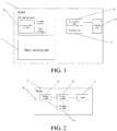
- FIG. 1 is a functional block diagram of a radar in the embodiments.
- a radar 1 includes a control unit 11, a transmitting unit 13, a receiving unit 14, and an antenna unit 15, and further includes another auxiliary unit 17.
- the control unit 11, the transmitting unit 13, the receiving unit 14, and the antenna unit 15 are integrated in one chip, and further, the other auxiliary unit 17 may also be integrated in the chip.
- the transmitting unit 13 is connected to a transmitting antenna 151
- the receiving unit 14 is connected to a receiving antenna 153.
- the transmitting unit 13 generates an electromagnetic wave signal and transmits the electromagnetic wave signal through the transmitting antenna 151, the receiving unit 14 receives an echo through the receiving antenna 153, and the control unit 11 obtains information such as a distance by analyzing the echo.
- the antenna unit 15 includes a transmitting antenna and a receiving antenna.
- the antenna unit may include one transmitting antenna and two or more receiving antennas, or two or more transmitting antennas and one receiving antenna, or two or more transmitting antennas and two or more receiving antennas.
- the transmitting antenna 151 and the receiving antenna 153 may be a same antenna.
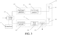
- FIG. 2 is schematic diagram of modules of an electric device according to the embodiments.
- an electric device 3 includes a body 31, a working module 39 configured to perform a work task, a control module 35 configured to obtain detection information of a sensor such as a radar 1 and control the working module 39, and an energy module 33 configured to provide energy for the electric device 3, where the working module 39, the control module 35, and the energy module 33 are all mounted on the body 31.
- the specific physical form of the control module 35 is a control circuit board provided with one or more processors, a memory, other related elements and devices, and a corresponding peripheral circuit.
- the control module 35 includes a built-in control program to execute a predetermined instruction and control the electric device 3 to perform a work task.
- the electric device 3 is further provided with the radar 1.
- the radar 1 can be integrated in a physical housing of a product. Because a radio signal can be transmitted through plastic and glass, a high degree of freedom is provided during designing a final product. In addition, because the radar 1 has a different wavelength from most of other electromechanical devices, the radar 1 faces a small signal interference risk and is not affected by a sound wave and light conditions. Because the radar 1 is a chip-type radar, the antennas is integrated inside the chip, and the integration is good, the radar 1 can be mounted at any position of the electric device 3 according to different usage scenarios, for example, at different positions such as an interior and an outer surface of the body 31, and can also be mounted on an ordinary PCB.
- the other auxiliary unit 17 of the radar 1 includes a power supply unit.
- the power supply unit includes low-dropout regulators and an enabling unit. Each low-dropout regulator provides a voltage of 1.8 V, and the enabling unit can generate a reset signal in each power supply circuit.
- the other auxiliary unit 17 of the radar 1 further includes a timing unit and the like.
- the radar 1 is a pulse coherent radar.
- a pulse-based radar system is configured to measure a transit time between a transmitting unit 13 and a receiving unit 14 in the process of measuring a wavelet.
- a reflected wavelet can be mixed with a locally generated reference wavelet, where the reference wavelet is delayed by a known time with respect to a transmitted wavelet.
- a delay achieving a maximum mixed product corresponds to the transit time above. Due to an impulsive nature of a measurement signal, the radar system of such a type is suitable for application desiring low power consumption.
- it is necessary to accurately control a delay between the reflected wavelet and the reference wavelet.
- the radar 1 is a synthetic aperture radar, which measures a distance based on a time difference between transmitting an electromagnetic pulse and receiving a target echo, and performs distance measurement and two-dimensional imaging based on a movement track of a platform, where two-dimensional coordinate information is distance information and azimuth information perpendicular to the distance, so as to detect a shape of a target object.
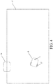
- FIG. 3 is a schematic diagram of a transmitting-receiving system of a pulse coherent radar in the embodiments.
- the pulse coherent radar includes a transmitting-receiving system.
- the system includes a transmitting unit 13, the transmitting unit 13 is configured to transmit a wavelet, and specifically, the transmitting unit 13 includes a first pulse generator 132 and a first wavelet generator 134.
- the system includes a receiving unit 14, the receiving unit 14 is configured to receive a wavelet, and specifically, the receiving unit 14 includes a second pulse generator 136 and a second wavelet generator 138 and further includes a correlator circuit 140.
- the system further includes a timing circuit 171, and the timing circuit 171 is configured to receive a reference clock signal, output a first trigger signal to trigger transmission of a wavelet, and output a second trigger signal to trigger generation of a reference wavelet.
- the first pulse generator 132 outputs a first pulse signal after receiving the first trigger signal from the timing circuit 171, and the first wavelet generator 134 outputs a wavelet in response to the first pulse signal.
- the second pulse generator 136 outputs a second pulse signal after receiving the second trigger signal from the timing circuit 171, and the second wavelet generator 138 outputs a reference wavelet in response to the second pulse signal.
- a wavelet refers to an electromagnetic oscillation signal having a certain amplitude envelope, and the amplitude envelope starts from zero amplitude, increases to a maximum amplitude, and then decreases to zero amplitude.
- a wavelet may include one or more oscillations.
- the first pulse generator is shown as a component separated from the first wavelet generator in FIG. 3 , but this separation is only made to facilitate understanding.
- a function of the first pulse generator 132 may be implemented in a same circuit as the first wavelet generator 134.
- a same wavelet generator can be used for generating both a wavelet to be transmitted and a reference wavelet.
- millimeter-level accuracy can be achieved in a distance measurement range within 2 meters, and a continuous scanning update rate can reach 1500 Hz.
- a radar 1 works in a millimeter-wave band.
- Millimeter wave refers to a frequency band from 30 GHz to 300 GHz (wavelength is 1-10 mm).
- a wavelength of a millimeter wave is between a centimeter wave and a light wave, and therefore, a millimeter wave has the advantages of microwave guidance and photoelectric guidance. Due to attenuation of a wireless signal, when signal transmission power is constant, the higher the frequency of a millimeter-wave radar, the shorter the detection range thereof.
- the radar 1 uses a license-free 60 GHz frequency band, and very small antennas and an ultra-short pulse can be used, thereby further achieving chip miniaturization and low power consumption.
- a power loss of the radar 1 is less than 50 mW.
- An update rate of the radar 1 is programmable, and performance can be optimized based on an expected usage scenario.
- an area of a chip where the radar 1 is located is less than 100 mm 2 .
- the chip has a size of 7.0 mm ⁇ 7.0 mm ⁇ 1.2 mm.
- an area of a chip where the radar 1 is located is less than 30 mm 2 .
- the chip has a size of 5.2mm ⁇ 5.2 mm ⁇ 0.88 mm. Certainly, due to different sizes and layouts of different components, the area of the chip changes accordingly.
- half-power point beamwidth of the radar 1 is 80 degrees in a horizontal direction and 40 degrees in a height direction.
- the radar 1 has a beam direction, and the beam direction refers to a maximum radiation direction of the radar 1.
- the radar 1 includes a rotation unit, one end of the rotation unit is fixed on an electric device 3, and a control unit 11 controls the rotation unit to rotate or stop, so as to drive the radar 1 to rotate or stop.
- a control unit 11 controls the rotation unit to rotate or stop, so as to drive the radar 1 to rotate or stop.
- the radar 1 transmits multiple electromagnetic waves, receives echoes, and calculates a spatial parameter and/or a physical parameter in a rotation plane.
- the electric device 3 is provided with two or more radars 1, which are arranged in a preset rule. Because a detection range of a chip-type radar is limited, mounting multiple radars 1 can increase the detection range of the radars 1, so as to meet detection requirements of the electric device 3.
- the preset rule may be a manner such as transverse mounting, longitudinal mounting, or circumferential mounting.
- a radar array is mounted on the electric device 3, that is, environmental information of a larger range is obtained through a combination of multiple radars 1.
- the half-power point beamwidth of the radar 1 in the horizontal direction is 80 degrees.
- radars 1 can be mounted in a same plane in a 2 ⁇ 2 arrangement, so that the detection range of the radars 1 can cover 360 degrees in the same plane. It can be understood that the number and arrangement of radars 1 can be adjusted according to specific detection requirements.
- the electric device 3 uses the radar 1 to perform environmental detection.
- the radar 1 transmits an electromagnetic wave.
- the electromagnetic wave would be reflected when hitting an obstacle in front.
- the radar 1 receives a reflected echo, and can obtain information such as a distance by analyzing the echo.
- a control module 35 controls a working module 39 and the like based on a detection result of the radar 1.
- the electric device 3 includes a self-moving device 5.
- front represents a heading direction of the self-moving device
- rear represents a direction opposite to "front”
- left represents a left side in the travel direction
- right represents a right side of the travel direction opposite to “left”
- up represents a direction away from a working surface of a machine during work
- down represents a direction close to the working surface of the machine and opposite to "up”.
- the self-moving device 5 includes a body 31, a radar 1 located on the body 31, a drive module 37 located at a bottom of the body 31, a working module 39 configured to perform work, a control module 35 configured to control the self-moving device 5 to automatically work and move, and an energy module 33 which provides energy for the self-moving device 5.
- the self-moving device 5 may be an intelligent lawn mower or a robotic vacuum cleaner or other devices that can move autonomously to complete work.
- the radar 1 is configured to identify a material type. Data detected by the radar 1 includes more information than simple distance and speed. A material can be classified by analyzing the data. In this embodiment, the radar 1 analyzes the data in combination with a dielectric constant of the material itself.
- the self-moving device 5 is a robotic vacuum cleaner.
- the control module 35 timely adjusts a height of the working module 39 by acquiring material information, to prevent reduction of work efficiency caused by the robotic vacuum cleaner being sucked on a working surface when entering a carpet and other surfaces.
- the radar 1 detects a foreign object such as spilled liquid or animal feces, the control module 35 can timely adjust a vacuuming manner to prevent the foreign object from further spreading.
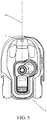
- FIG. 4 is a schematic diagram of an automatic working system in one of embodiments.
- a self-moving device 5 travels and works in a working region 55 specified by a user.
- the self-moving device 5 is an intelligent lawn mower, and a working surface in the working region 55 of the user is a lawn.
- a radar 1 can distinguish a material type of a surface detected, and a control module 35 controls the self-moving device 5 within the working region 55 based on an identification result of the radar 1.
- the control module 35 determines that the self-moving device 5 reaches a boundary of the working region 55, and controls a drive module 37 to move back or turn.
- the radar 1 is mounted below the self-moving device 5 and faces a surface to be detected.
- a beam direction of the radar 1 is perpendicular to the surface to be detected.
- the radar 1 can not only identify whether the surface detected is a lawn, but also identify different types and density of grass in a lawn.
- lawn grass such as cool-season grass and warm-season grass. Different varieties of grass grow in different ways, and have different growth density, stem and leave sizes, and hardness. There may even be many varieties of grass planted in a same lawn.
- a working mode of the self-moving device 5, including setting of a working plan, a travelling mode of the drive module 37, a working mode of a working module 39, and the like, can be adjusted accordingly, so as to ensure working efficiency of the self-moving device 5.
- the radar 1 identifies hardness or density of a lawn by analyzing an echo, and the control module 35 adjusts the working mode of the self-moving device 5 based on an identification result of the radar 1, so as to improve cutting efficiency of the self-moving device 5.
- the working module 39 includes a cutting motor.
- a lawn having high density may cause original output torque of the cutting motor to be insufficient to complete an original cutting amount, then the control module 35 controls the cutting motor to increase output torque. It can be understood that if the radar identifies that the density of a lawn is high and this may cause incomplete cutting of the lawn in a region in which the self-moving device 5 travels at an original travelling speed, the travelling speed of the drive module 37 can be reduced.
- the radar 1 is mounted on a front side of the self-moving device 5, and has a beam direction diagonally down toward a surface that the self-moving device 5 will pass, and there is an included angle between the beam direction and a surface to be detected.
- the radar 1 can detect a surface in front of the self-moving device 5 in advance, and the control module 35 makes a prediction based on a detection result, and controls the drive module 37 to decelerate or turn, or the like.
- the radar 1 detects a distance between the surface in front and the self-moving device 5 and a material type of the surface in front, and the control module 35 can determine, based on results of the above detection, whether there is a region such as a pit or a pool which cannot be entered on the surface in front, so as to control the drive module 37 to turn, thereby preventing the self-moving device 5 from entering such a region.
- FIG. 5 is a schematic diagram of a self-moving device in one of embodiments.
- a radar 1 is mounted on a front side of a self-moving device 5 and faces a heading direction of the self-moving device 5 to detect an obstacle in the heading direction.
- a control module 35 controls a drive module 37 to move back or turn to prevent the self-moving device 5 from being damaged by collision with the obstacle.
- a beam direction 10 of the radar 1 is parallel to a surface where the heading direction of the self-moving device 5 is located.
- the self-moving device 5 may also be provided with radars 1 at other positions, including a rear side or other circumferential directions such as left and right of the self-moving device 5, to detect obstacles in corresponding directions.
- radars 1 are mounted on left and right sides of the self-moving device 5, and the control module 35 performs determining by using detection results of the radars 1, so that the self-moving device 5 can pass the narrow passage more efficiently.
- a preset distance for obstacle detection is set in the control module 35, and when a distance between the self-moving device 5 and an obstacle is less than or equal to the preset distance, the self-moving device 5 avoids the obstacle and does not continue moving toward the obstacle, thereby achieving non-contact obstacle avoidance of the self-moving device 5.
- Different obstacle avoidance purposes can be achieved through different preset distance values. When the distance is relatively small, relatively short-distance non-contact obstacle avoidance can be achieved, and when the distance is relatively large, long-distance non-contact obstacle avoidance with respect to the short-distance non-contact obstacle avoidance can be achieved.
- the effective detection range of the radar 1 covers a region directly in front of the body 31 of the self-moving device 5, so that the radar 1 can detect an obstacle directly in front of the self-moving device 5 during travelling, thereby preventing the self-moving device from colliding with the obstacle during travelling.
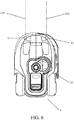
- FIG. 6 is a schematic diagram of a radar axis relationship in one of embodiments. Taking a left-right direction of a self-moving device 5 as a width direction, an effective detection width of a radar 1 needs to cover a width of a body 31. Transmitting and receiving ranges of antennas of a radar are limited. To ensure that an effective monitoring range of the radar 1 can cover the width of the body 31, in an embodiment, as shown in FIG. 6 , a first radar 11 and a second radar 13 are mounted on a front side of the self-moving device 5, a first beam direction 110 of the first radar 11 and a second beam direction 130 of the second radar 13 are parallel to each other, and a detection range is towards the heading direction of the self-moving device 5.
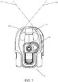
- FIG. 7 is a schematic diagram of radar arrangement and detection range in one of embodiments.
- a first radar 11 and a second radar 13 are mounted on a self-moving device 5 at an angle, so that a first beam direction 110 and a second beam direction 130 intersect, thereby reducing a detection blind region of a radar 1 in a short range, and achieving short-distance obstacle avoidance.
- a location and a direction of an obstacle are obtained through echo reception, thereby improving the obstacle positioning accuracy and helping the self-moving device 5 adapt to different working conditions.
- a control module 35 can also take a targeted obstacle avoidance measure based on the direction of the obstacle. It can be understood that radars 1 can be combined differently according to requirements for layout, for example, four radars 1 can be used for forming four detection regions to further accurately position an obstacle.
- the control module 35 when the radar 1 detects an obstacle, the control module 35 further obtains a result of analysis on a material type of the obstacle by the radar 1. If the radar 1 detects an obstacle and then the control module 35 immediately controls a drive module 37 to move back or turn, a lawn around the obstacle cannot be cut. After obtaining a material type of the obstacle, the control module 35 can determine properties such as hardness of the material according to the material type.
- the control module 35 determines that this situation is an unsafe situation and controls the drive module 37 to move back or turn; if an obstacle has low hardness and collision of the self-moving device 5 with the obstacle would not cause damage or other problems, the control module 35 determines that this situation is a safe situation, and controls the drive module 37 to continue travelling in a heading direction, and when a collision is detected, the control module 35 controls the drive module 37 to move back.
- an obstacle may be a fragile object that is not suitable for collision, and if the radar 1 detects such a material type, the control module 35 controls the drive module 37 to move back or turn to avoid collision with the obstacle.
- the radar 1 identifies a vital sign of an obstacle, and if a vital sign of the obstacle is detected, the control module 35 controls, based on the vital sign detected by the radar 1, the drive module to turn so that the self-moving device avoids the obstacle having the vital sign.
- the radar 1 identifies whether an obstacle is a human body or other animal, and the control module 35 controls, based on a detection result of the radar 1, the drive module 37 to move back or turn so that the self-moving device 5 moves away from the human body.
- the radar 1 can identify a human body or an animal by detecting a vital sign such as respiration or pulse.
- the self-moving device 5 is an intelligent lawn mower.
- a working module 39 may cause injury to a user due to accidental contact by the user during working, and therefore, a shield needs to be mounted around the working module 39 to avoid injuries.
- the provision of the shield makes the self-moving device 5 unable to complete cutting to an edge. In this embodiment, for better cutting to an edge, the manner of providing the shield can be changed.
- the radar 1 is mounted outside the working module 39, and multiple radars 1 are mounted, so as to ensure that a human body can be detected when approaching the working module 39 within a certain range. When the radar 1 detects a human body, the control module 35 controls the working module 39 to stop working to avoid injuries to the human body.
- an effective distance can be preset, for example, 1 meter, and when the radar identifies a human body within 1 meter, the control module 35 controls the working module 39 to stop working.
- an electric device 3 is an electric tool 7.
- the electric tool 7 includes: a body 31; a working module 39 mounted on the body 31 to fit with a working head 40 and output power to the working head 40; a control module 35 mounted on the body 31 and configured to control the working module 39; and an energy module 33 mounted on the body 31 and configured to provide energy to the working module 39 and/or the control module 35.
- the electric tool 7 in the embodiments may be a tool that completes a work task on a working surface, such as an electric drill, an electric hammer, an electric pick, a sanding machine, and a swing machine.
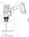
- FIG. 8 is a schematic diagram of an electric drill in one of embodiments.
- an electric tool 7 is an electric drill.
- a working module 39 includes: a drive motor, provided in a body 31 and outputs rotation power, and further includes an output shaft, provided in the body 31 and connected to a working head 40 to drive the working head 40 to work, and having an output shaft axis.
- the body 31 has a body 31 front end for receiving the output shaft and axially extending along the output shaft axis.
- the radar 1 is mounted at the body 31 front end and has a detection range towards a working surface 70 of the electric drill. In a preferred embodiment, a beam direction of the radar 1 is perpendicular to the working surface 70.
- the radar 1 is configured to detect a material type of the working surface 70 of the electric tool 7, and the control module 35 controls a parameter of the working head 40 based on a detection result of the radar 1.
- the electric tool 7 is an electric drill, and generally, different working surfaces 70 need to correspond to different working heads 40 to complete drilling work more efficiently.
- optimal correspondences between different working surfaces 70 and working heads 40 are configured in the control module 35, for example, a drill bit corresponding to a working surface 70 of metal and the like is a twisted metal drill bit, a drill bit corresponding to a working surface 70 of wood or plastic and the like is a woodworking drill bit, and the like.
- an indicator light is further mounted on the body 31, and is controlled by the control module 35.
- the radar 1 starts to identify the working surface 70 in a detection direction, and if the control module 35 determines that the working surface 70 does not match the working head 40, the control module 35 controls the indicator light to flash to prompt a user to replace the drill bit.
- the correspondences are not absolute, for example, a twisted metal drill bit is also suitable for wood.
- the control module 35 can also configure sub-optimal correspondences other than the optimal correspondences.
- the electric tool 7 further includes a communication module, which can communicate with other user equipment. When determining that the working surface 70 does not match the working head 40, the control module 35 sends prompt information to user equipment through the communication module to prompt the user to replace the working head 40.
- the radar 1 is configured to detect the material type of the working surface 70 of the electric tool 7, and the control module 35 controls a working mode of the electric tool 7 based on a detection result of the radar 1.
- the electric tool 7 is an electric hammer
- a working module 39 of the electric hammer includes a drive motor, and a motor shaft, a bevel gear shaft, an intermediate shaft, and an output shaft which are connected to the drive motor.
- the motor shaft can transmit power to the output shaft through the bevel gear shaft or the intermediate shaft.
- the intermediate shaft can be provided with a pendulum bearing to drive the output shaft to perform impact motion.
- the bevel gear shaft can drive the output shaft to rotate, to make the electric hammer in a drill gear or a hammer drill gear.
- the drill gear is mainly suitable for a working surface 70 having relatively low hardness, such as metal, wood, and plastic, and the hammer drill gear is mainly suitable for concrete, stone, and the like.
- the control module 35 prompts the user to switch the working mode.
- the control module 35 may be configured to automatically switch the working mode according to the material type of the working surface 70 detected by the radar 1 to provide a more efficient and convenient working mode.
- the radar 1 is configured to detect the material type of the working surface 70 of the electric tool 7, and the control module 35 controls torque based on a detection result of the radar 1.
- the electric tool 7 is a sanding machine
- a working module 39 includes a drive motor, a motor shaft fixedly connected to the drive motor, and an eccentric device fitted with the drive motor, where a bottom plate is fitted with the eccentric device.
- the radar 1 starts to identify the working surface 70 in a detection direction, and if the radar 1 identifies that the material type of the working surface 70 does not match current output torque, the control module 35 adjusts output torque of the drive motor based on a detection result of the radar 1 so that the output torque matches the working surface 70, thereby improving the polishing efficiency.
- the radar 1 is configured to detect a distance between the radar 1 and a reference surface 72.
- the electric tool 7 is an electric drill
- a hole depth setting module is mounted on a body 31, connected to a control module 35, and configured to set a drilling depth.
- the reference surface 72 is a surface where a working head 40 is located when the electric tool 7, i.e., an electric drill, starts to work. If the working surface 70 of the electric drill is flat, an initial working surface 70 when the electric drill starts to work is the reference surface 72. Before the electric drill works, a user sets the drilling depth to D by the hole depth setting module.
- the working module 39 of the electric tool 7 includes a moving element
- the radar 1 is configured to detect a distance between the moving element and the user, and when the distance is less than a preset distance, the control module 35 controls the working module 39 to stop working, so as to prevent the moving element from injuring the user.
- the electric tool 7 is an electric saw
- the moving element is a blade.
- the control module 35 controls a working module to stop working to prevent the user from contacting the moving blade.
- a beam direction of the radar 1 faces the moving element, and when the user approaches the moving element, the radar 1 can timely detect the user.
Landscapes
- Engineering & Computer Science (AREA)
- Remote Sensing (AREA)
- Radar, Positioning & Navigation (AREA)
- Physics & Mathematics (AREA)
- General Physics & Mathematics (AREA)
- Computer Networks & Wireless Communication (AREA)
- Mechanical Engineering (AREA)
- Automation & Control Theory (AREA)
- Electromagnetism (AREA)
- Life Sciences & Earth Sciences (AREA)
- Aviation & Aerospace Engineering (AREA)
- Wood Science & Technology (AREA)
- Forests & Forestry (AREA)
- Robotics (AREA)
- Radar Systems Or Details Thereof (AREA)
Applications Claiming Priority (2)
| Application Number | Priority Date | Filing Date | Title |
|---|---|---|---|
| CN201810669338 | 2018-06-26 | ||
| PCT/CN2019/093086 WO2020001490A1 (zh) | 2018-06-26 | 2019-06-26 | 应用雷达的电动设备 |
Publications (2)
| Publication Number | Publication Date |
|---|---|
| EP3816652A1 true EP3816652A1 (de) | 2021-05-05 |
| EP3816652A4 EP3816652A4 (de) | 2022-03-16 |
Family
ID=68986206
Family Applications (1)
| Application Number | Title | Priority Date | Filing Date |
|---|---|---|---|
| EP19825539.0A Withdrawn EP3816652A4 (de) | 2018-06-26 | 2019-06-26 | Elektrische vorrichtung, die radar anwendet |
Country Status (4)
| Country | Link |
|---|---|
| US (1) | US20210263131A1 (de) |
| EP (1) | EP3816652A4 (de) |
| CN (1) | CN112424629B (de) |
| WO (1) | WO2020001490A1 (de) |
Cited By (1)
| Publication number | Priority date | Publication date | Assignee | Title |
|---|---|---|---|---|
| SE2250671A1 (en) * | 2022-06-03 | 2023-12-04 | Husqvarna Ab | Enhanced drive motor control in a robotic lawnmower |
Families Citing this family (14)
| Publication number | Priority date | Publication date | Assignee | Title |
|---|---|---|---|---|
| CN113970918A (zh) * | 2020-07-10 | 2022-01-25 | 苏州宝时得电动工具有限公司 | 一种自动行走设备 |
| EP3968051B1 (de) * | 2020-09-15 | 2024-10-30 | Infineon Technologies AG | Führungssystem für einen roboter, basisstation mit einem solchen führungssystem und verfahren zum führen eines roboters |
| US12210086B2 (en) * | 2020-10-13 | 2025-01-28 | Google Llc | Smart-device-based radar system performing location tagging |
| US12296694B2 (en) | 2021-03-10 | 2025-05-13 | Techtronic Cordless Gp | Lawnmowers |
| US12443180B2 (en) | 2021-11-10 | 2025-10-14 | Techtronic Cordless Gp | Robotic lawn mowers |
| CN114264360A (zh) * | 2021-12-07 | 2022-04-01 | 深圳市博悠半导体科技有限公司 | 基于雷达的物体识别方法、装置及智能电子秤 |
| AU2023200381A1 (en) | 2022-01-31 | 2023-08-17 | Techtronic Cordless Gp | Robotic garden tool |
| EP4270138A1 (de) | 2022-04-28 | 2023-11-01 | Techtronic Cordless GP | Erzeugung einer virtuellen grenze für ein robotisches gartenwerkzeug |
| US12472611B2 (en) | 2022-05-31 | 2025-11-18 | Techtronic Cordless Gp | Peg driver |
| US20240000018A1 (en) * | 2022-06-29 | 2024-01-04 | Techtronic Cordless Gp | Controlling movement of a robotic garden tool with respect to one or more detected objects |
| AU2023204696A1 (en) | 2022-07-19 | 2024-02-08 | Techtronic Cordless Gp | Display for controlling robotic tool |
| AU2023206123A1 (en) | 2022-07-29 | 2024-02-15 | Techtronic Cordless Gp | Generation of a cryptography key for a robotic garden tool |
| SE548179C2 (en) * | 2024-02-06 | 2026-04-13 | Husqvarna Ab | Enhanced behavior for a robotic lawnmower that has left a grass surface |
| CN118915059A (zh) * | 2024-07-23 | 2024-11-08 | 复睿智行智能科技(上海)有限公司 | 一种多功能毫米波雷达系统及其使用方法 |
Family Cites Families (50)
| Publication number | Priority date | Publication date | Assignee | Title |
|---|---|---|---|---|
| US5511238A (en) * | 1987-06-26 | 1996-04-23 | Texas Instruments Incorporated | Monolithic microwave transmitter/receiver |
| GB9601528D0 (en) * | 1996-01-25 | 1996-03-27 | Chignell Richard J | Underground pipe locating system |
| DE102004059333A1 (de) * | 2004-12-09 | 2006-06-14 | Robert Bosch Gmbh | Antennenanordnung für einen Radar-Transceiver |
| DE102004059332A1 (de) * | 2004-12-09 | 2006-06-14 | Robert Bosch Gmbh | Radar-Transceiver |
| DE102005046044A1 (de) * | 2005-09-27 | 2007-03-29 | Robert Bosch Gmbh | Radar-Sensor |
| DE102005049130A1 (de) * | 2005-10-14 | 2007-04-19 | Robert Bosch Gmbh | Handwerkzeugmaschine |
| DE102005056756A1 (de) * | 2005-11-29 | 2007-05-31 | Robert Bosch Gmbh | Antennenanordnung für einen Radar-Sensor |
| US7379017B2 (en) * | 2006-01-24 | 2008-05-27 | Raytheon Company | Micro movement pulsed radar system and method of phase noise compensation |
| DE102006061581A1 (de) * | 2006-12-27 | 2008-07-03 | Robert Bosch Gmbh | Elektrowerkzeugvorrichtung |
| DE102006062492A1 (de) * | 2006-12-28 | 2008-07-03 | Robert Bosch Gmbh | Hochfrequenzsensor sowie Werkzeugmaschine mit einem Hochfrequenzsensor |
| JP2008191088A (ja) * | 2007-02-07 | 2008-08-21 | Toshiba Corp | レーダ装置 |
| CN201307245Y (zh) * | 2008-12-04 | 2009-09-09 | 杭州亿脑智能科技有限公司 | 割草机器人导航系统 |
| DE102009030076A1 (de) * | 2009-06-23 | 2010-12-30 | Symeo Gmbh | Abbildungsverfahren mittels synthetischer Apertur, Verfahren zur Bestimmung einer Relativgeschwindigkeit zwischen einem wellenbasierten Sensor und einem Objekt bzw. Vorrichtung zur Durchführung der Verfahren |
| EP2387932A1 (de) * | 2010-05-20 | 2011-11-23 | Koninklijke Philips Electronics N.V. | Vorrichtung zum Reinigen einer Oberfläche mit mindestens einer Drehbürste |
| CN101975951B (zh) * | 2010-06-09 | 2013-03-20 | 北京理工大学 | 一种融合距离和图像信息的野外环境障碍检测方法 |
| CN102540204B (zh) * | 2010-12-31 | 2014-10-29 | 杭州中科微电子有限公司 | 一种单芯片双频全球卫星导航接收机 |
| CN102423261B (zh) * | 2011-09-20 | 2013-10-02 | 中国人民解放军第四军医大学 | 超宽谱雷达式非接触生命参数实时监测系统 |
| CN104755002B (zh) * | 2012-12-18 | 2017-09-08 | 阿尔弗雷德·凯驰两合公司 | 用于地面清洁设备的清洁刷以及带清洁刷的地面清洁设备 |
| DE102013202075A1 (de) * | 2013-02-08 | 2014-08-14 | Robert Bosch Gmbh | Bewegungsstrategieerarbeitungs- und/oder Navigationsvorrichtung |
| CN103941306B (zh) * | 2014-01-13 | 2017-02-01 | 苏州爱普电器有限公司 | 清洁机器人及用于控制其避开障碍物的方法 |
| CN104081942A (zh) * | 2014-07-03 | 2014-10-08 | 安庆市鸿裕工业产品设计有限公司 | 保护刀具的割草机组件 |
| US9618611B2 (en) * | 2014-09-24 | 2017-04-11 | Nxp B.V. | Personal radar assistance |
| DE102014014860B3 (de) * | 2014-10-06 | 2015-09-17 | Audi Ag | Radarsensoranordnung und Kraftfahrzeug |
| US9733340B2 (en) * | 2014-11-21 | 2017-08-15 | Texas Instruments Incorporated | Techniques for high arrival angle resolution using multiple nano-radars |
| DE102015209101A1 (de) * | 2015-05-19 | 2016-11-24 | Robert Bosch Gmbh | Verfahren zum Erzeugen einer Karte für ein autonomes Fahrzeug |
| DE102015007040B4 (de) * | 2015-05-30 | 2020-09-24 | Audi Ag | Verfahren zur Detektion und Klassifikation von Fußgängern in einer Umgebung eines Kraftfahrzeugs und Kraftfahrzeug |
| CN104933708A (zh) * | 2015-06-07 | 2015-09-23 | 浙江大学 | 一种基于多谱三维特征融合的植被环境中障碍物检测方法 |
| EP3115804A1 (de) * | 2015-07-08 | 2017-01-11 | dSPACE digital signal processing and control engineering GmbH | Prüfstand zum test eines abstandsradargeräts zur entfernungs- und geschwindigkeitsbestimmung von hindernissen |
| EP3325917B1 (de) * | 2015-07-17 | 2020-02-26 | trinamiX GmbH | Detektor zur optischen detektion von mindestens einem objekt |
| CN115211274A (zh) * | 2015-12-17 | 2022-10-21 | 苏州宝时得电动工具有限公司 | 割草机 |
| CN105433860B (zh) * | 2015-12-25 | 2018-01-23 | 杭州它人机器人技术有限公司 | 一种智能地面清洁机器人 |
| CN107024928B (zh) * | 2016-02-01 | 2020-04-28 | 松下家电研究开发(杭州)有限公司 | 一种智能扫地机器人及智能扫地机器人控制方法 |
| CN105866790B (zh) * | 2016-04-07 | 2018-08-10 | 重庆大学 | 一种考虑激光发射强度的激光雷达障碍物识别方法及系统 |
| EP3459334B1 (de) * | 2016-05-19 | 2022-09-07 | Positec Power Tools (Suzhou) Co., Ltd. | Selbstbewegende vorrichtung und steuerungsverfahren dafür |
| EP3508049B1 (de) * | 2016-06-30 | 2022-08-24 | Techtronic Outdoor Products Technology Limited | Autonomer rasenmäher |
| CN107622666B (zh) * | 2016-07-13 | 2020-11-24 | 尚艳燕 | 一种平衡车巡航执法方法和装置 |
| CN107783116A (zh) * | 2016-08-25 | 2018-03-09 | 大连楼兰科技股份有限公司 | 无人驾驶汽车复杂环境防撞毫米波雷达系统 |
| CN107783115A (zh) * | 2016-08-25 | 2018-03-09 | 大连楼兰科技股份有限公司 | 旋翼无人机远距离复杂环境防撞毫米波雷达系统 |
| WO2018085095A1 (en) * | 2016-11-07 | 2018-05-11 | The Climate Corporation | Work layer imaging and analysis for implement monitoring, control and operator feedback |
| CN106333631B (zh) * | 2016-11-11 | 2022-03-08 | 北京地平线机器人技术研发有限公司 | 可移动清洁设备及其控制方法 |
| CN106377209B (zh) * | 2016-11-11 | 2022-07-22 | 北京地平线机器人技术研发有限公司 | 可移动清洁设备及其控制方法 |
| US10620310B2 (en) * | 2016-11-29 | 2020-04-14 | Waymo Llc | Rotating radar platform |
| CN206431284U (zh) * | 2016-12-30 | 2017-08-22 | 北京行易道科技有限公司 | 雷达及交通工具 |
| CN206990798U (zh) * | 2016-12-30 | 2018-02-09 | 北京行易道科技有限公司 | 雷达 |
| CN207148321U (zh) * | 2017-03-21 | 2018-03-27 | 坎德拉(深圳)科技创新有限公司 | 障碍物检测装置 |
| CN107132913A (zh) * | 2017-03-31 | 2017-09-05 | 南京理工大学 | 一种基于毫米波的多用户人机交互方法 |
| CN106901665A (zh) * | 2017-04-17 | 2017-06-30 | 沈昱成 | 多功能模块化智能家居服务机器人 |
| CN107548232A (zh) * | 2017-09-29 | 2018-01-05 | 北京微度芯创科技有限责任公司 | 毫米波雷达芯片和天线的集成封装件 |
| CN107690939A (zh) * | 2017-11-15 | 2018-02-16 | 宁夏智源农业装备有限公司 | 割草机以及割草系统 |
| US10852390B2 (en) * | 2017-12-20 | 2020-12-01 | Waymo Llc | Multiple polarization radar unit |
-
2019
- 2019-06-26 CN CN201980040393.XA patent/CN112424629B/zh active Active
- 2019-06-26 WO PCT/CN2019/093086 patent/WO2020001490A1/zh not_active Ceased
- 2019-06-26 EP EP19825539.0A patent/EP3816652A4/de not_active Withdrawn
- 2019-06-26 US US17/255,311 patent/US20210263131A1/en not_active Abandoned
Cited By (2)
| Publication number | Priority date | Publication date | Assignee | Title |
|---|---|---|---|---|
| SE2250671A1 (en) * | 2022-06-03 | 2023-12-04 | Husqvarna Ab | Enhanced drive motor control in a robotic lawnmower |
| SE546203C2 (en) * | 2022-06-03 | 2024-07-02 | Husqvarna Ab | Method for controlling a robotic lawnmower in dependence of analysis of information acquired by means of a radar transceiver and a control unit therefor |
Also Published As
| Publication number | Publication date |
|---|---|
| CN112424629A (zh) | 2021-02-26 |
| US20210263131A1 (en) | 2021-08-26 |
| CN112424629B (zh) | 2024-04-09 |
| WO2020001490A1 (zh) | 2020-01-02 |
| EP3816652A4 (de) | 2022-03-16 |
Similar Documents
| Publication | Publication Date | Title |
|---|---|---|
| EP3816652A1 (de) | Elektrische vorrichtung, die radar anwendet | |
| KR102834783B1 (ko) | 레이더 데이터 결합 시스템 및 방법 | |
| CN113156364B (zh) | 安全系统和方法 | |
| WO2019119243A1 (zh) | 无人机避障方法及无人机 | |
| CN215813854U (zh) | 一种自动行走设备 | |
| CN109426264A (zh) | 自移动设备及其移动路径的控制方法 | |
| CN107783115A (zh) | 旋翼无人机远距离复杂环境防撞毫米波雷达系统 | |
| WO2018192396A1 (zh) | 一种相控阵识别方法及系统 | |
| EP3732506B1 (de) | Autonomer mobiler reinigungsroboter | |
| EP3911973A1 (de) | Verbesserte kollisionsdetektion für ein roboterarbeitswerkzeug | |
| AU2014201836A1 (en) | Apparatus for Measuring the Position of a Vehicle or a Surface thereof | |
| CN113759377A (zh) | 自移动设备定位方法、装置、存储介质、设备及系统 | |
| CN107783116A (zh) | 无人驾驶汽车复杂环境防撞毫米波雷达系统 | |
| CN107783128A (zh) | 基于毫米波雷达的固定翼无人机多目标防撞系统 | |
| CN107783118A (zh) | 基于毫米波雷达的固定翼无人机多目标防撞系统的防撞方法 | |
| CN107783123A (zh) | 无人驾驶汽车复杂环境防撞毫米波雷达信号处理系统及方法 | |
| US20210333401A1 (en) | Distance measuring device, point cloud data application method, sensing system, and movable platform | |
| CN107783114A (zh) | 旋翼无人机远距离复杂环境防撞毫米波雷达信号处理系统及方法 | |
| CN205656309U (zh) | 小型红外测距装置 | |
| US12444994B2 (en) | Antenna device, feed system, feed device, and feed method | |
| AU2014201914B2 (en) | Method for Measuring the Position of a Surface of a Vehicle | |
| RU2005103453A (ru) | Способ контроля воздушного пространства, облучаемого внешними источниками излучения, и радиолокационная станция для его реализации | |
| US20230176584A1 (en) | Guidance for an outdoor robotic work tool to an outdoor robotic work tool interaction station | |
| CN214906430U (zh) | 雷达地毯识别装置及扫地机器人 | |
| CN107144245B (zh) | 测量高度的系统及测量高度的方法 |
Legal Events
| Date | Code | Title | Description |
|---|---|---|---|
| STAA | Information on the status of an ep patent application or granted ep patent |
Free format text: STATUS: THE INTERNATIONAL PUBLICATION HAS BEEN MADE |
|
| PUAI | Public reference made under article 153(3) epc to a published international application that has entered the european phase |
Free format text: ORIGINAL CODE: 0009012 |
|
| STAA | Information on the status of an ep patent application or granted ep patent |
Free format text: STATUS: REQUEST FOR EXAMINATION WAS MADE |
|
| 17P | Request for examination filed |
Effective date: 20210126 |
|
| AK | Designated contracting states |
Kind code of ref document: A1 Designated state(s): AL AT BE BG CH CY CZ DE DK EE ES FI FR GB GR HR HU IE IS IT LI LT LU LV MC MK MT NL NO PL PT RO RS SE SI SK SM TR |
|
| DAV | Request for validation of the european patent (deleted) | ||
| DAX | Request for extension of the european patent (deleted) | ||
| REG | Reference to a national code |
Ref country code: DE Ref legal event code: R079 Free format text: PREVIOUS MAIN CLASS: G01S0007000000 Ipc: G01S0007030000 |
|
| A4 | Supplementary search report drawn up and despatched |
Effective date: 20220215 |
|
| RIC1 | Information provided on ipc code assigned before grant |
Ipc: B27G 21/00 20060101ALI20220209BHEP Ipc: B25F 5/00 20060101ALI20220209BHEP Ipc: B23B 49/00 20060101ALI20220209BHEP Ipc: A47L 9/28 20060101ALI20220209BHEP Ipc: G01S 13/88 20060101ALI20220209BHEP Ipc: G01S 7/03 20060101AFI20220209BHEP |
|
| STAA | Information on the status of an ep patent application or granted ep patent |
Free format text: STATUS: EXAMINATION IS IN PROGRESS |
|
| 17Q | First examination report despatched |
Effective date: 20240304 |
|
| P01 | Opt-out of the competence of the unified patent court (upc) registered |
Effective date: 20240312 |
|
| STAA | Information on the status of an ep patent application or granted ep patent |
Free format text: STATUS: THE APPLICATION IS DEEMED TO BE WITHDRAWN |
|
| 18D | Application deemed to be withdrawn |
Effective date: 20240705 |