EP3816596B1 - Regelung der temperaturänderungsrate für einen trockenblockkalibrator - Google Patents
Regelung der temperaturänderungsrate für einen trockenblockkalibrator Download PDFInfo
- Publication number
- EP3816596B1 EP3816596B1 EP20203759.4A EP20203759A EP3816596B1 EP 3816596 B1 EP3816596 B1 EP 3816596B1 EP 20203759 A EP20203759 A EP 20203759A EP 3816596 B1 EP3816596 B1 EP 3816596B1
- Authority
- EP
- European Patent Office
- Prior art keywords
- temperature
- actual temperature
- change
- dry block
- rate
- Prior art date
- Legal status (The legal status is an assumption and is not a legal conclusion. Google has not performed a legal analysis and makes no representation as to the accuracy of the status listed.)
- Active
Links
Images


Classifications
-
- G—PHYSICS
- G01—MEASURING; TESTING
- G01K—MEASURING TEMPERATURE; MEASURING QUANTITY OF HEAT; THERMALLY-SENSITIVE ELEMENTS NOT OTHERWISE PROVIDED FOR
- G01K15/00—Testing or calibrating of thermometers
- G01K15/002—Calibrated temperature sources, temperature standards therefor
-
- G—PHYSICS
- G05—CONTROLLING; REGULATING
- G05D—SYSTEMS FOR CONTROLLING OR REGULATING NON-ELECTRIC VARIABLES
- G05D23/00—Control of temperature
- G05D23/19—Control of temperature characterised by the use of electric means
- G05D23/1919—Control of temperature characterised by the use of electric means characterised by the type of controller
-
- F—MECHANICAL ENGINEERING; LIGHTING; HEATING; WEAPONS; BLASTING
- F25—REFRIGERATION OR COOLING; COMBINED HEATING AND REFRIGERATION SYSTEMS; HEAT PUMP SYSTEMS; MANUFACTURE OR STORAGE OF ICE; LIQUEFACTION SOLIDIFICATION OF GASES
- F25B—REFRIGERATION MACHINES, PLANTS OR SYSTEMS; COMBINED HEATING AND REFRIGERATION SYSTEMS; HEAT PUMP SYSTEMS
- F25B21/00—Machines, plants or systems, using electric or magnetic effects
- F25B21/02—Machines, plants or systems, using electric or magnetic effects using Peltier effect; using Nernst-Ettinghausen effect
- F25B21/04—Machines, plants or systems, using electric or magnetic effects using Peltier effect; using Nernst-Ettinghausen effect reversible
-
- G—PHYSICS
- G01—MEASURING; TESTING
- G01K—MEASURING TEMPERATURE; MEASURING QUANTITY OF HEAT; THERMALLY-SENSITIVE ELEMENTS NOT OTHERWISE PROVIDED FOR
- G01K15/00—Testing or calibrating of thermometers
- G01K15/005—Calibration
-
- G—PHYSICS
- G01—MEASURING; TESTING
- G01K—MEASURING TEMPERATURE; MEASURING QUANTITY OF HEAT; THERMALLY-SENSITIVE ELEMENTS NOT OTHERWISE PROVIDED FOR
- G01K3/00—Thermometers giving results other than momentary value of temperature
- G01K3/08—Thermometers giving results other than momentary value of temperature giving differences of values; giving differentiated values
- G01K3/10—Thermometers giving results other than momentary value of temperature giving differences of values; giving differentiated values in respect of time, e.g. reacting only to a quick change of temperature
Definitions
- the present invention relates to temperature calibrations, and such procedures applied in temperature calibrators (i.e. dry blocks), which are widely used in various industrial processes and plants, for instance.
- Temperature calibrators are measurement units which can be made for industrial field use, and they can be manufactured as relatively small-sized units to be carriable around a plant, Temperature calibrators can also be called as dry blocks or dry block calibrators, meaning exactly the same. Temperature calibrators may be manufactured in different temperature range variations, e.g. by having a dry block which is suitable for calibrating temperatures of - 25 °C ... + 150 °C, and another dry block for calibrating temperatures of + 50 °C ... + 660 °C, to merely give some examples on different temperature range options.
- the temperature in the calibrator block needs to be measured and regulated, and a part of the process is to create a stable temperature environment for the temperature probes (i.e. sensors) to be calibrated in the calibrator block.
- Temperature regulation in a dry block is typically done with a PID regulator.
- FIG. 1 illustrates a manner as a flow chart in which the temperature is usually regulated in a temperature calibrator (i.e. in a dry block), by using a PID regulator (i.e. a proportional-integral-derivative regulator).
- FIG. 1 is shown as a block diagram, which comprises a regulator 12, a control element 13, a calibrator block 14 and a temperature sensor 15. Furthermore, there is a summing block 11, and the calibrator block 14 outputs the actual temperature.
- the temperature sensor 15 output is marked as "PV", a Process Variable, i.e. the measured temperature of the calibrator block 14.
- SP is the Set Point, i.e. a wanted temperature of the calibrator block 14.
- MV is the Manipulated Variable, i.e. the output signal from the regulator 12 in a suitable unit, e.g. in Watts or Amperes.
- MV is fed into the control element 13, and the control element 13 outputs "PQ", which is the Physical Quantity, i.e. an actual physical quantity (such as power in Watts or current in Amperes) which causes the calibrator block 14 to change temperature.
- This type of simple regulation depicted in FIG. 1 often suffers from temperature oscillation in the calibrator block 14, when approaching the temperature set-point. Such oscillations, especially the overshoots, are not desirable for accurate temperature probe calibration, as overshoots may cancel out the temperature sensing hysteresis in the temperature probe to be calibrated. When we want to measure hysteresis, we must not cancel out the hysteresis.
- FIG. 2 illustrates temperature behavior with an overshoot in an example of the situation using a PID regulator of FIG. 1 , shown as a graph with time in an X-axis and temperature of the calibrator block in a Y-axis.
- the regulating action is "too quick” or “too harsh”, resulting in the temperature going over the desired temperature in a relatively short time period, and thereafter resulting in an oscillating manner of the temperature, until the desired temperature is in practice reached after a certain oscillating time period.
- the oscillations can typically be reduced or removed totally.
- the temperature set-point changes can be made very slow by appropriate parameter adjustments using the PID regulator of FIG. 1 .
- Keen discloses a temperature control system for constant temperature ovens. Keen addresses the possibility of temperature overshoot during the initial warm-up period. This disclosure slows up the rate of change of temperature as the actual temperature approaches the desired operating temperature so that thermal inertia does not carry the actual temperature beyond the range of temperatures over which the controlling crystal can exercise control.
- US 2016/174749 discloses a sous-vide cooker. It involves a cooking chamber, a heating system and a housing comprising these elements.
- the heating system comprises a heating unit, one or more temperature sensors, a PID controller (a calibrated one), and a control panel.
- the device maintains a constant water temperature within tolerances.
- the derivative term slows the rate of change of the controller output and this effect is most noticeable close to the controller setpoint.
- derivative control is used to reduce the magnitude of the overshoot produced by the integral component and improve the combined controller-process stability.
- Han discloses a temperature conditioning system staging control and method.
- a further object of Han is to eliminate the need for anticipation means in the control, while minimizing overshoot of the zone setpoint.
- Han discloses a control for a multi-stage heating and cooling system used to temperature conditioning a comfort zone.
- the control includes a microprocessor responsive to a temperature sensor installed in the comfort zone.
- Heating and cooling setpoints and a lookup table including a plurality of ranges for deviation of the comfort zone from the setpoint temperature and associated limits for the rate of change of the comfort zone temperature used in determining specific staging control actions are stored in solid state memory accessed by the microprocessor.
- the stages of temperature conditioning are controlled as a function of both the deviation of the zone temperature from the heating or cooling setpoint (depending on the system operating mode), and the rate of change of zone temperature.
- the mode of operation i.e., heating or cooling, is determined by the relative values of the zone temperature and the heating and cooling setpoint.
- the invention comprises a method for regulating temperature in a dry block calibrator as defined by independent claim 1 as well as an arrangement for regulating temperature in a dry block calibrator as defined by independent claim 8 and a computer program for carrying out the inventive method as defined by independent claim 9.
- the present invention represents a method for regulating the temperature in a calibrator block, which method is particularly suitable for dry block calibrators.
- the purpose is to, instead of regulating the temperature directly, regulate the temperature velocity (i.e. the rate of change of the temperature) using a PID regulator, and have the velocity set-point follow predetermined velocity paths, when approaching the temperature set-point.
- the actual approaching process of the temperature set-point is under strict control.
- the velocity can be high, but close to the temperature set-point, the desired velocity is decreased and very close to the temperature set-point, the desired velocity is reduced to almost zero, so that the temperature slowly crawls up to the temperature set-point without overshooting.
- velocity regulation allows us to create stable temperature ramps needed for calibrating the activation and deactivation points of temperature switches i.e. switches which activate or deactivate at certain temperatures. This is an advantage of the invention.
- a PID regulator according to the present invention may comprise the following functional elements as shown in FIG. 4 .
- SP T is the Temperature Set Point, i.e. a wanted/desired temperature of the calibrator block 14.
- SP T is fed into a summing unit 11.
- Another signal entering the summing unit 11 i.e. a first summing unit
- the PV T i.e. Temperature Process Variable
- SPv enter a second summing unit 22.
- Max velocity means a maximum temperature velocity [in unit °C/s] which the block “A” 21 may output; this value is fixed and can be set by the user for the block “A” 21.
- PVv means a Velocity Process Variable, a measured temperature velocity [°C/s] in calibrator block 14.
- the temperature sensor 15 senses the actual temperature of the calibrator block 14, and a derivator 24 calculates and output its rate of change as a function of time, resulting in the Velocity Process Variable PVv.
- derivator 24 converts the measured temperature into a measured temperature velocity (i.e. rate of change) [°C/s].
- MVv i.e. Velocity Manipulated Variable
- MVv i.e. Velocity Manipulated Variable
- Block "B" takes both the Velocity Manipulated Variable and the temperature sensor 15 output as its input signals. Note that blocks "A" 21 and "B” 23 are discussed in more detail in the following paragraphs.
- Block “B” 23 will output "RQ", meaning a Regulated Quantity, i.e. a regulated quantity output from block “B” 23 in a suitable unit, e.g. in Watts or Amperes.
- This signal, RQ is directed to the control element 13.
- control element 13 will output "PQ” based on input "RQ” (not input MV anymore like in FIG. 1 ).
- PQ is a Physical Quantity, i.e. an actual physical quantity, such as power in Watts or current in Amperes, that causes the calibrator block 14 to change temperature.
- Blocks "A" 21, "B” 23 and derivator 24 are needed for having the regulator 12 operate in the so-called velocity domain which is called this way because the regulator is in this way elevated up to a higher domain.
- a base domain here would be the temperature itself, the velocity of the temperature change would be the next higher domain, and the temperature change acceleration would be the next higher domain.
- derivator 24 is a main functional block in the embodiments of the present invention.
- Block “A” 21 continuously evaluates the calibrator block's 14 temperature state with respect to the temperature set-point and other factors, and provides a "wanted velocity" to be kept by the regulator 12. The regulator 12 then outputs a "corrected velocity” that block "B" 23 converts to a suitable electrical quantity.
- the conversion method may differ depending on the type of the calibrator block 14.
- Block "A” 21 continuously calculates the velocity set-point SPv from the three input signals; E T , PV T and Max velocity; and calculates the velocity set-point SPv.
- the velocity set-point SPv is calculated so that the temperature in the calibrator block 14 will approach the temperature set-point without overshoots.
- the appropriate approach path is dependent on both the distance from the target set-point E T as well as the sensed temperature PV T .
- SPv is limited to not exceed the Max velocity value in the discussed embodiment according to FIG. 4 .
- a dry block calibrator utilizes Peltier elements (a.k.a. thermoelectric coolers (TEC)) as heating elements (meaning that the calibrator block's typical temperature range is +150 ... -30 °C)
- the output quantity from block "B" 23 is selected to be current in Amperes.
- the relationship between current and velocity at different calibrator block temperatures has been determined by measuring and characterizing an existing calibrator block assembly and the measurement data has been collected in a multi-dimensional lookup table, which block "B" 23 uses to convert between velocity in °C/s and current in Amperes.
- the lookup table does not give a perfect conversion, but the velocity regulator will compensate for these conversion errors.
- the output quantity from block "B" 23 is selected to be power in Watts.
- the conversion is done according to the following mathematical principles, presented in equations (1)-(17) in the following paragraphs.
- the rate of change of energy is the time derivative of equation (1).
- Rate of change of energy is the time derivative of the above equation (3).
- E ⁇ ⁇ n E ⁇ out
- Steady state power can be measured at different temperatures and given as a polynomial.
- q tot is the total heatloss including natural convection, radiation and conduction to other parts. It equals to steady state power that can be measured. Since we know the heating power P heating and heating speed can be easily measured, mc p can be calculated at different temperatures and given as a polynomial.
- Controlled cooling means applying power in heaters when cooling (i.e. simultaneous cooling and heating).
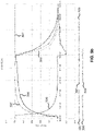
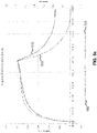
- FIG:s 5a-c illustrate actual measurement results concerning the velocity regulator implementation relating to temperature changes, for the "cold" dry block utilizing Peltier elements in an embodiment of the invention.
- the measurements have been performed at a set-point change from 20 °C to 50 °C, when the user has limited the velocity by setting "Max velocity" to 0,1 °C/s.
- the set-point change takes approximately 9 minutes to complete.
- FIG. 5a shows graphs representing temperatures: SP T , PV T , E T and a temperature measurement inside the calibrator block insert using an external reference sensor (this measurement corresponds closely to the "Actual temperature", which the sensors to be calibrated experience).
- the notation corresponds to the one presented earlier in the disclosure.
- the time-lag between the external reference sensor in the insert and the PV T sensor (which is the internal reference sensor in the calibrator block). This is because these two sensors are at different locations in the thermodynamic assembly.
- the PV T sensor is closer to the heating and cooling sources (the Peltier elements in this measurement), and therefore it registers changes in temperature sooner than the external reference sensor.
- FIG. 5b shows graphs representing velocities in °C/s: PVv, Ev, Max velocity, MVv and SPv. The notation corresponds to the one presented earlier in the disclosure here as well.
- FIG. 5c shows regulator output velocity MVv in the y-axis on the left, and regulated quantity RQ in the y-axis on the right.
- the velocity is shown in °C/s and the regulated quantity RQ is shown as a current in A.
- aspects of the present invention thus comprise a method for temperature velocity regulation in temperature calibrators, and a temperature velocity regulator in temperature calibrators.
- the method can be applied by software (i.e. a computer program, and/or a respective computer program product), which can be stored in a memory of the temperature calibrator, and executed by a processor or controller controlling the temperature calibrator.
- the temperature calibrator may have an I/O interface like a keyboard and a screen, or a touch screen for information feeding and presenting.
- the temperature calibrator may also have output connection means for wired or wireless communication means for information transfer e.g. to a remote computer or server in the cloud. Wireless transfer means then also comprises appropriate radio signal transmission means, comprising an antenna as well.
Landscapes
- Physics & Mathematics (AREA)
- General Physics & Mathematics (AREA)
- Engineering & Computer Science (AREA)
- Automation & Control Theory (AREA)
- Mechanical Engineering (AREA)
- Thermal Sciences (AREA)
- General Engineering & Computer Science (AREA)
- Control Of Temperature (AREA)
- Measuring Temperature Or Quantity Of Heat (AREA)
- Feedback Control In General (AREA)
Claims (9)
- Verfahren zur Regelung der Temperatur in einem Trockenblockkalibrator (14), wobei der Trockenblockkalibrator (14) einen Prozessor umfasst, wobei das Verfahren die folgenden Schritte umfasst:- Messen einer tatsächlichen Temperatur (PVT) des Trockenblockkalibrators (14) durch einen Temperatursensor (15);- Anlegen eines von einem Temperaturfehler (ET) abgeleiteten Signals an einen Regler (12), wobei das Temperaturfehlersignal (ET) ein Temperatursollwert (SPT) abzüglich der tatsächliche Temperatur (PVT) ist; und- Zuführen einer von einem Ausgangssignal des Reglers (12) abgeleiteten geregelten Größe (RQ) zu einem Steuerelement (13), wobei das Steuerelement (13) die geregelte Größe (RQ) in eine physikalische Größe (PQ) umwandelt, die an den Trockenblockkalibrator (14) zur Regelung der Temperatur ausgegeben wird;dadurch gekennzeichnet, dass das Verfahren ferner die folgenden Schritte umfasst:- Berechnen einer Änderungsrate (PVV) der tatsächlichen Temperatur (PVT) des Trockenblockkalibrators (14) durch einen Ableiter (24), wobei der Ableiter (24) die tatsächliche Temperatur (PVT) als Eingang nimmt;- Berechtigen eines Benutzers, um eine maximale Änderungsrate der tatsächlichen Temperatur (PVT) als Eingabewert an den Prozessor zu spezifizieren; und- Regeln der tatsächlichen Temperatur (PVT) des Trockenblockkalibrators (14) vom Prozessor, so dass die maximale Änderungsrate der Temperatur niemals überschritten wird, und so dass während der Temperaturregelung, wenn das Temperaturfehlersignal (ET) als Funktion der Zeit abnimmt, die Änderungsrate der tatsächlichen Temperatur (PVT) auch in Abhängigkeit von der Zeit abnimmt, und das- ein erstes Funktionselement (21) die tatsächliche Temperatur (PVT), das Temperaturfehlersignal (ET) und die spezifizierte maximale Änderungsrate der tatsächlichen Temperatur (PVT) als seine Eingänge nimmt, und das erste Funktionselement (21) einen Geschwindigkeitssollwert (SPV) ausgibt, und das- der Geschwindigkeitssollwert (SPV) abzüglich der von dem Ableiter (24) berechneten Änderungsrate (PVV) der tatsächlichen Temperatur (PVT) dem Regler (12) als Geschwindigkeitsfehlersignal (EV) zugeführt wird.
- Verfahren nach Anspruch 1, dadurch gekennzeichnet, dass die Regelung der Temperatur des Trockenblockkalibrators (14) vom Regler (12) auf der Grundlage des Temperaturfehlersignals (ET), der tatsächlichen Temperatur (PVT) und der von dem Ableiter (24) berechneten Änderungsrate (PVV) der tatsächlichen Temperatur (PVT) durchgeführt wird.
- Verfahren nach Anspruch 1, dadurch gekennzeichnet, dass ein zweites Funktionselement (23) den Ausgang des Reglers (12), der eine Geschwindigkeitsstellgröße (MVV) ist, und die tatsächliche Temperatur (PVT), als seine Eingänge nimmt, und das zweite Funktionselement (23) die geregelte Größe (RQ) an das Steuerelement (13) ausgibt.
- Verfahren nach Anspruch 3, dadurch gekennzeichnet, dass der Trockenblockkalibrator (14) Peltier-Elemente als Heizelemente aufweist, wenn die geregelte Größe (RQ) Strom in Ampere ist.
- Verfahren nach Anspruch 4, dadurch gekennzeichnet, dass eine durch das zweite Funktionselement (23) vorgenommene Umrechnung zwischen der Geschwindigkeitsstellgröße (MVV) in °C/s und dem Strom der geregelten Größe (RQ) in Ampere durch Anwendung einer Nachschlagetabelle durchgeführt wird, wobei die Nachschlagetabelle durch Messen eines vorhandenen Trockenblockkalibrators vorher gefüllt wurde.
- Verfahren nach Anspruch 3, dadurch gekennzeichnet, dass der Trockenblockkalibrator (14) Widerstandsheizungen als Heizelemente umfasst, wenn die geregelte Größe (RQ) Leistung in Watt ist.
- Verfahren nach Anspruch 6, dadurch gekennzeichnet, dass eine durch das zweite Funktionselement (23) vorgenommene Umrechnung zwischen der Geschwindigkeitsstellgröße (MVV) in °C/s und der Leistung der geregelten Größe (RQ) in Watt durch Anwenden mehrerer thermischer Energiegleichungen durchgeführt wird.
- Anordnung zur Regelung der Temperatur in einem Trockenblockkalibrator (14), wobei der Trockenblockkalibrator (14) einen Prozessor umfasst, wobei die Anordnung Folgendes umfasst:- einen Temperatursensor (15), der dazu konfiguriert ist, eine tatsächliche Temperatur (PVT) des Trockenblockkalibrators (14) zu messen;- einen Regler (12), der so konfiguriert ist, dass er als Eingang ein von einem Temperaturfehler (ET) abgeleitetes Signal nimmt, wobei das Temperaturfehlersignal (ET) ein Temperatursollwert (SPT) abzüglich der tatsächlichen Temperatur (PVT) ist; und- ein Steuerelement (13), das dazu konfiguriert ist, eine von einem Ausgangssignal des Reglers (12) abgeleitete geregelte Größe (RQ) als seinen Eingang zu nehmen, wobei das Steuerelement (13) ferner so konfiguriert ist, dass es die geregelte Größe (RQ) in eine physikalische Größe (PQ) umwandelt, die an den Trockenblockkalibrator (14) zur Regelung der Temperatur ausgegeben wird;dadurch gekennzeichnet, dass die Anordnung ferner Folgendes umfasst:- einen Ableiter (24), der konfiguriert ist, um eine Änderungsrate (PVV) der tatsächlichen Temperatur (PVT) des Trockenblockkalibrators (14) zu berechnen, wobei der Ableiter (24) ferner so konfiguriert ist, dass er die tatsächliche Temperatur (PVT) als seine Eingabe nimmt; und- Mittel, die so konfiguriert sind, dass sie einen Benutzer berechtigen, eine maximale Änderungsrate der tatsächlichen Temperatur (PVT) als einen Eingabewert für den Prozessor zu spezifizieren; und wo- der Prozessor so konfiguriert ist, dass er die tatsächliche Temperatur (PVT) des Trockenblockkalibrators (14) regelt, so dass die maximale Änderungsrate der Temperatur niemals überschritten wird, und so dass während der Temperaturregelung, wenn das Temperaturfehlersignal (ET) als Funktion der Zeit abnimmt, die Änderungsrate der tatsächlichen Temperatur (PVT) auch als Funktion der Zeit abnimmt, und- ein erstes Funktionselement (21), das so konfiguriert ist, dass es die tatsächliche Temperatur (PVT), das Temperaturfehlersignal (ET) und die spezifizierte maximale Änderungsrate der tatsächlichen Temperatur (PVT) als seine Eingänge nimmt, wobei das erste Funktionselement (21) ferner dazu konfiguriert ist, einen Geschwindigkeitssollwert (SPV) auszugeben, wobei die Anordnung so konfiguriert ist, dass- der Geschwindigkeitssollwert (SPV) abzüglich der Änderungsrate (PVV) der tatsächlichen Temperatur (PVT), die durch den Ableiter (24) berechnet wird, dem Regler (12) als ein Geschwindigkeitsfehlersignal (EV) zugeführt wird.
- Computerprogramm zur Regelung der Temperatur in einem Trockenblockkalibrator (14), wobei der Trockenblockkalibrator (14) einen Prozessor umfasst und das Computerprogramm einen Programmcode umfasst und in dem Prozessor ausführbar ist, wobei das Computerprogramm konfiguriert ist, die folgenden Schritte auszuführen:- Messen einer tatsächlichen Temperatur (PVT) des Trockenblockkalibrators (14) durch einen Temperatursensor (15);- Anlegen eines von einem Temperaturfehler (ET) abgeleiteten Signals an einen Regler (12), wobei das Temperaturfehlersignal (ET) ein Temperatursollwert (SPT) abzüglich der tatsächlichen Temperatur (PVT) ist; und- Zuführen einer von einem Ausgangssignal des Reglers (12) abgeleiteten geregelten Größe (RQ) zu einem Steuerelement (13), wobei das Steuerelement (13) die geregelte Größe (RQ) in eine physikalische Größe (PQ) umwandelt, die an den Trockenblockkalibrator (14) zur Regelung der Temperatur ausgegeben wird;dadurch gekennzeichnet, dass das Computerprogramm ferner so konfiguriert ist, dass es die folgenden Schritte ausführt:- Berechnen einer Änderungsrate (PVV) der tatsächlichen Temperatur (PVT) des Trockenblockkalibrators (14) durch einen Ableiter (24), wobei der Ableiter (24) die tatsächliche Temperatur (PVT) als seine Eingabe nimmt;- Berechtigen eines Benutzers, eine maximale Änderungsrate der tatsächlichen Temperatur (PVT) als Eingabewert für den Prozessor zu spezifizieren; und- Regeln der tatsächlichen Temperatur (PVT) des Trockenblockkalibrators (14) durch den Prozessor, so dass die maximale Änderungsrate der Temperatur niemals überschritten wird, und so dass während der Temperaturregelung, wenn das Temperaturfehlersignal (ET) als Funktion der Zeit abnimmt, die Änderungsrate der tatsächlichen Temperatur (PVT) auch als Funktion der Zeit abnimmt, und dass- ein erstes Funktionselement (21) als Eingänge die tatsächliche Temperatur (PVT), das Temperaturfehlersignal (ET) und die spezifizierte maximale Änderungsrate der tatsächlichen Temperatur (PVT) nimmt, und das erste Funktionselement (21) einen Geschwindigkeitssollwert (SPV) ausgibt, und dass- der Geschwindigkeitssollwert (SPV) abzüglich der Änderungsrate (PVV) der tatsächlichen Temperatur (PVT), die durch den Ableiter (24) berechnet wird, dem Regler (12) als ein Geschwindigkeitsfehlersignal (EV) zugeführt wird.
Applications Claiming Priority (1)
| Application Number | Priority Date | Filing Date | Title |
|---|---|---|---|
| FI20195925A FI129720B (en) | 2019-10-28 | 2019-10-28 | CALIBRATOR BLOCK SPEED ADJUSTMENT IN TEMPERATURE CALIBRATOR |
Publications (2)
| Publication Number | Publication Date |
|---|---|
| EP3816596A1 EP3816596A1 (de) | 2021-05-05 |
| EP3816596B1 true EP3816596B1 (de) | 2022-10-05 |
Family
ID=73014407
Family Applications (1)
| Application Number | Title | Priority Date | Filing Date |
|---|---|---|---|
| EP20203759.4A Active EP3816596B1 (de) | 2019-10-28 | 2020-10-26 | Regelung der temperaturänderungsrate für einen trockenblockkalibrator |
Country Status (3)
| Country | Link |
|---|---|
| US (1) | US11740140B2 (de) |
| EP (1) | EP3816596B1 (de) |
| FI (1) | FI129720B (de) |
Families Citing this family (2)
| Publication number | Priority date | Publication date | Assignee | Title |
|---|---|---|---|---|
| US11836028B2 (en) * | 2021-01-20 | 2023-12-05 | Dell Products L.P. | System and method for closed-loop memory power capping |
| US11519625B2 (en) * | 2021-04-13 | 2022-12-06 | Emerson Electric Co. | Managing temperature overshoot |
Family Cites Families (16)
| Publication number | Priority date | Publication date | Assignee | Title |
|---|---|---|---|---|
| US2975261A (en) * | 1958-09-11 | 1961-03-14 | Lavoie Lab Inc | Temperature control system |
| US3939687A (en) * | 1974-07-15 | 1976-02-24 | King Nutronics Corporation | Temperature calibration system |
| US4246641A (en) * | 1979-02-26 | 1981-01-20 | The Perkin-Elmer Corporation | Automatic temperature calibration of thermal analyzers |
| US4501125A (en) * | 1983-12-05 | 1985-02-26 | The Trane Company | Temperature conditioning system staging control and method |
| US4924173A (en) * | 1989-02-06 | 1990-05-08 | Troxler Electronic Laboratories, Inc. | Shielded capacitance standard |
| NO305295B1 (no) * | 1997-07-18 | 1999-05-03 | Instrutek Holding As | Innretning for kalibrering av temperaturf°lere |
| EP1988375A1 (de) * | 2007-05-03 | 2008-11-05 | Renishaw plc | Verfahren und Vorrichtung zur schnellen Temperaturmessung |
| WO2010040360A1 (en) | 2008-10-10 | 2010-04-15 | Ametek Denmark A/S | A calibration apparatus |
| AU2010293067B2 (en) | 2009-09-08 | 2017-04-06 | Daniel J. Eades | Sous- vide cooker |
| DE102014007786A1 (de) | 2014-05-23 | 2015-11-26 | SIKA Dr. Siebert & Kühn GmbH & Co. KG | Verfahren und Vorrichtung zur Regelung der Temperatur des Kalibriervolumens einer Einrichtung zum vergleichenden Kalibrieren von Temperatursensoren |
| DE102015122037B4 (de) * | 2015-12-17 | 2017-12-07 | Netzsch-Gerätebau GmbH | Verfahren zur thermischen Analyse einer Probe und/oder zur Kalibrierung einer Temperaturmesseinrichtung |
| DE102016123856A1 (de) | 2016-12-08 | 2018-06-14 | Endress + Hauser Wetzer Gmbh + Co. Kg | Verfahren zur in situ Kalibrierung eines Thermometers |
| EP3739314B1 (de) * | 2018-01-09 | 2024-08-21 | Beijing Const Instruments Technology Inc. | Strömungsführung und wärmeableitender trockenblocktemperaturkalibrator |
| FI129008B (en) * | 2019-10-28 | 2021-05-14 | Beamex Oy Ab | ADVANCED SAFETY MECHANISMS IN THE INTELLIGENT TEMPERATURE CALIBRATOR |
| FI129727B (en) * | 2019-10-28 | 2022-08-15 | Beamex Oy Ab | IMPROVEMENT, DETECTION AND DISPLAY OF STABILITY IN AN INDUSTRIAL TEMPERATURE CALIBRATOR |
| FI131042B1 (en) * | 2019-10-28 | 2024-08-13 | Beamex Oy Ab | Temperature calibrator with advanced functionalities |
-
2019
- 2019-10-28 FI FI20195925A patent/FI129720B/en active IP Right Grant
-
2020
- 2020-10-26 US US17/080,593 patent/US11740140B2/en active Active
- 2020-10-26 EP EP20203759.4A patent/EP3816596B1/de active Active
Also Published As
| Publication number | Publication date |
|---|---|
| FI129720B (en) | 2022-07-29 |
| EP3816596A1 (de) | 2021-05-05 |
| US20220128419A1 (en) | 2022-04-28 |
| US20230266179A9 (en) | 2023-08-24 |
| US11740140B2 (en) | 2023-08-29 |
| FI20195925A1 (en) | 2021-04-29 |
Similar Documents
| Publication | Publication Date | Title |
|---|---|---|
| US5179265A (en) | Cooking time control system for conveyor ovens | |
| CN112672664B (zh) | 控制护发器具的方法 | |
| KR20020039316A (ko) | 디지털 유량 조절기용 시스템 및 방법 | |
| CN105094168A (zh) | 对比较式地校准温度传感器的装置的校准容积的温度进行调节的方法和设备 | |
| CN114690636B (zh) | 基于机理参数在线修正的反应量热系统模型预测控温方法 | |
| WO2004017035A2 (en) | Method and apparatus for temperature control | |
| US11740140B2 (en) | Velocity regulation of the calibrator block in a dry block calibrator | |
| EP1161712B1 (de) | Verfahren und vorrichtung zum optimieren der umgebungstemperatur eines getesteten objektes | |
| JP7753347B2 (ja) | エネルギーの制御を使用した電気ヒーターの制御のための方法およびシステム | |
| CN202734509U (zh) | 一种隧道炉温度控制系统 | |
| JP5464326B2 (ja) | 物理量制御装置、物理量制御方法及び物理量制御プログラム | |
| JP6500976B2 (ja) | 温度制御システム及び温度制御方法 | |
| JP3829575B2 (ja) | 温度調節器および熱処理装置 | |
| CN108955249A (zh) | 一种隧道炉温度控制系统及控制方法 | |
| JP3664125B2 (ja) | 制御装置、温度調節器および熱処理装置 | |
| JPH0772927A (ja) | 形状記憶合金アクチュエータ制御装置 | |
| JPWO2006061892A1 (ja) | 温度制御方法、及び温度制御装置 | |
| EP3246783A2 (de) | Adaptives vorsteuerungsverfahren zur temperaturregelung | |
| US20250264222A1 (en) | Adjusting a cooking cycle according to thermal attributes of cookware items | |
| RU2384872C2 (ru) | Способ автоматической оптимальной импульсной настройки системы управления | |
| CA1332292C (en) | Temperature controlling means for a thermostat for use in measuring viscosity | |
| CN121326045A (zh) | 一种晶圆加热盘的标定方法和温度控制装置 | |
| WO2025033063A1 (ja) | 脱脂炉、脱脂炉の温度制御方法および脱脂炉の温度制御プログラム | |
| Stefanac et al. | Evolution of process controls toward factory automation | |
| Boháč | Dynamic behaviour of the panel radiator |
Legal Events
| Date | Code | Title | Description |
|---|---|---|---|
| PUAI | Public reference made under article 153(3) epc to a published international application that has entered the european phase |
Free format text: ORIGINAL CODE: 0009012 |
|
| STAA | Information on the status of an ep patent application or granted ep patent |
Free format text: STATUS: THE APPLICATION HAS BEEN PUBLISHED |
|
| AK | Designated contracting states |
Kind code of ref document: A1 Designated state(s): AL AT BE BG CH CY CZ DE DK EE ES FI FR GB GR HR HU IE IS IT LI LT LU LV MC MK MT NL NO PL PT RO RS SE SI SK SM TR |
|
| STAA | Information on the status of an ep patent application or granted ep patent |
Free format text: STATUS: REQUEST FOR EXAMINATION WAS MADE |
|
| GRAP | Despatch of communication of intention to grant a patent |
Free format text: ORIGINAL CODE: EPIDOSNIGR1 |
|
| STAA | Information on the status of an ep patent application or granted ep patent |
Free format text: STATUS: GRANT OF PATENT IS INTENDED |
|
| 17P | Request for examination filed |
Effective date: 20211104 |
|
| RBV | Designated contracting states (corrected) |
Designated state(s): AL AT BE BG CH CY CZ DE DK EE ES FI FR GB GR HR HU IE IS IT LI LT LU LV MC MK MT NL NO PL PT RO RS SE SI SK SM TR |
|
| INTG | Intention to grant announced |
Effective date: 20211210 |
|
| GRAJ | Information related to disapproval of communication of intention to grant by the applicant or resumption of examination proceedings by the epo deleted |
Free format text: ORIGINAL CODE: EPIDOSDIGR1 |
|
| STAA | Information on the status of an ep patent application or granted ep patent |
Free format text: STATUS: REQUEST FOR EXAMINATION WAS MADE |
|
| GRAS | Grant fee paid |
Free format text: ORIGINAL CODE: EPIDOSNIGR3 |
|
| STAA | Information on the status of an ep patent application or granted ep patent |
Free format text: STATUS: GRANT OF PATENT IS INTENDED |
|
| GRAP | Despatch of communication of intention to grant a patent |
Free format text: ORIGINAL CODE: EPIDOSNIGR1 |
|
| INTC | Intention to grant announced (deleted) | ||
| INTG | Intention to grant announced |
Effective date: 20220511 |
|
| GRAA | (expected) grant |
Free format text: ORIGINAL CODE: 0009210 |
|
| STAA | Information on the status of an ep patent application or granted ep patent |
Free format text: STATUS: THE PATENT HAS BEEN GRANTED |
|
| AK | Designated contracting states |
Kind code of ref document: B1 Designated state(s): AL AT BE BG CH CY CZ DE DK EE ES FI FR GB GR HR HU IE IS IT LI LT LU LV MC MK MT NL NO PL PT RO RS SE SI SK SM TR |
|
| REG | Reference to a national code |
Ref country code: GB Ref legal event code: FG4D |
|
| REG | Reference to a national code |
Ref country code: CH Ref legal event code: EP |
|
| REG | Reference to a national code |
Ref country code: AT Ref legal event code: REF Ref document number: 1523003 Country of ref document: AT Kind code of ref document: T Effective date: 20221015 |
|
| REG | Reference to a national code |
Ref country code: DE Ref legal event code: R096 Ref document number: 602020005469 Country of ref document: DE |
|
| REG | Reference to a national code |
Ref country code: IE Ref legal event code: FG4D |
|
| REG | Reference to a national code |
Ref country code: LT Ref legal event code: MG9D |
|
| REG | Reference to a national code |
Ref country code: NL Ref legal event code: MP Effective date: 20221005 |
|
| REG | Reference to a national code |
Ref country code: AT Ref legal event code: MK05 Ref document number: 1523003 Country of ref document: AT Kind code of ref document: T Effective date: 20221005 |
|
| PG25 | Lapsed in a contracting state [announced via postgrant information from national office to epo] |
Ref country code: NL Free format text: LAPSE BECAUSE OF FAILURE TO SUBMIT A TRANSLATION OF THE DESCRIPTION OR TO PAY THE FEE WITHIN THE PRESCRIBED TIME-LIMIT Effective date: 20221005 |
|
| PG25 | Lapsed in a contracting state [announced via postgrant information from national office to epo] |
Ref country code: SE Free format text: LAPSE BECAUSE OF FAILURE TO SUBMIT A TRANSLATION OF THE DESCRIPTION OR TO PAY THE FEE WITHIN THE PRESCRIBED TIME-LIMIT Effective date: 20221005 Ref country code: PT Free format text: LAPSE BECAUSE OF FAILURE TO SUBMIT A TRANSLATION OF THE DESCRIPTION OR TO PAY THE FEE WITHIN THE PRESCRIBED TIME-LIMIT Effective date: 20230206 Ref country code: NO Free format text: LAPSE BECAUSE OF FAILURE TO SUBMIT A TRANSLATION OF THE DESCRIPTION OR TO PAY THE FEE WITHIN THE PRESCRIBED TIME-LIMIT Effective date: 20230105 Ref country code: LT Free format text: LAPSE BECAUSE OF FAILURE TO SUBMIT A TRANSLATION OF THE DESCRIPTION OR TO PAY THE FEE WITHIN THE PRESCRIBED TIME-LIMIT Effective date: 20221005 Ref country code: FI Free format text: LAPSE BECAUSE OF FAILURE TO SUBMIT A TRANSLATION OF THE DESCRIPTION OR TO PAY THE FEE WITHIN THE PRESCRIBED TIME-LIMIT Effective date: 20221005 Ref country code: ES Free format text: LAPSE BECAUSE OF FAILURE TO SUBMIT A TRANSLATION OF THE DESCRIPTION OR TO PAY THE FEE WITHIN THE PRESCRIBED TIME-LIMIT Effective date: 20221005 Ref country code: AT Free format text: LAPSE BECAUSE OF FAILURE TO SUBMIT A TRANSLATION OF THE DESCRIPTION OR TO PAY THE FEE WITHIN THE PRESCRIBED TIME-LIMIT Effective date: 20221005 |
|
| PG25 | Lapsed in a contracting state [announced via postgrant information from national office to epo] |
Ref country code: RS Free format text: LAPSE BECAUSE OF FAILURE TO SUBMIT A TRANSLATION OF THE DESCRIPTION OR TO PAY THE FEE WITHIN THE PRESCRIBED TIME-LIMIT Effective date: 20221005 Ref country code: PL Free format text: LAPSE BECAUSE OF FAILURE TO SUBMIT A TRANSLATION OF THE DESCRIPTION OR TO PAY THE FEE WITHIN THE PRESCRIBED TIME-LIMIT Effective date: 20221005 Ref country code: LV Free format text: LAPSE BECAUSE OF FAILURE TO SUBMIT A TRANSLATION OF THE DESCRIPTION OR TO PAY THE FEE WITHIN THE PRESCRIBED TIME-LIMIT Effective date: 20221005 Ref country code: IS Free format text: LAPSE BECAUSE OF FAILURE TO SUBMIT A TRANSLATION OF THE DESCRIPTION OR TO PAY THE FEE WITHIN THE PRESCRIBED TIME-LIMIT Effective date: 20230205 Ref country code: HR Free format text: LAPSE BECAUSE OF FAILURE TO SUBMIT A TRANSLATION OF THE DESCRIPTION OR TO PAY THE FEE WITHIN THE PRESCRIBED TIME-LIMIT Effective date: 20221005 Ref country code: GR Free format text: LAPSE BECAUSE OF FAILURE TO SUBMIT A TRANSLATION OF THE DESCRIPTION OR TO PAY THE FEE WITHIN THE PRESCRIBED TIME-LIMIT Effective date: 20230106 |
|
| REG | Reference to a national code |
Ref country code: BE Ref legal event code: MM Effective date: 20221031 |
|
| PG25 | Lapsed in a contracting state [announced via postgrant information from national office to epo] |
Ref country code: LU Free format text: LAPSE BECAUSE OF NON-PAYMENT OF DUE FEES Effective date: 20221026 |
|
| P01 | Opt-out of the competence of the unified patent court (upc) registered |
Effective date: 20230526 |
|
| REG | Reference to a national code |
Ref country code: DE Ref legal event code: R097 Ref document number: 602020005469 Country of ref document: DE |
|
| PG25 | Lapsed in a contracting state [announced via postgrant information from national office to epo] |
Ref country code: SM Free format text: LAPSE BECAUSE OF FAILURE TO SUBMIT A TRANSLATION OF THE DESCRIPTION OR TO PAY THE FEE WITHIN THE PRESCRIBED TIME-LIMIT Effective date: 20221005 Ref country code: RO Free format text: LAPSE BECAUSE OF FAILURE TO SUBMIT A TRANSLATION OF THE DESCRIPTION OR TO PAY THE FEE WITHIN THE PRESCRIBED TIME-LIMIT Effective date: 20221005 Ref country code: MC Free format text: LAPSE BECAUSE OF FAILURE TO SUBMIT A TRANSLATION OF THE DESCRIPTION OR TO PAY THE FEE WITHIN THE PRESCRIBED TIME-LIMIT Effective date: 20221005 Ref country code: EE Free format text: LAPSE BECAUSE OF FAILURE TO SUBMIT A TRANSLATION OF THE DESCRIPTION OR TO PAY THE FEE WITHIN THE PRESCRIBED TIME-LIMIT Effective date: 20221005 Ref country code: DK Free format text: LAPSE BECAUSE OF FAILURE TO SUBMIT A TRANSLATION OF THE DESCRIPTION OR TO PAY THE FEE WITHIN THE PRESCRIBED TIME-LIMIT Effective date: 20221005 Ref country code: CZ Free format text: LAPSE BECAUSE OF FAILURE TO SUBMIT A TRANSLATION OF THE DESCRIPTION OR TO PAY THE FEE WITHIN THE PRESCRIBED TIME-LIMIT Effective date: 20221005 |
|
| PLBE | No opposition filed within time limit |
Free format text: ORIGINAL CODE: 0009261 |
|
| STAA | Information on the status of an ep patent application or granted ep patent |
Free format text: STATUS: NO OPPOSITION FILED WITHIN TIME LIMIT |
|
| PG25 | Lapsed in a contracting state [announced via postgrant information from national office to epo] |
Ref country code: SK Free format text: LAPSE BECAUSE OF FAILURE TO SUBMIT A TRANSLATION OF THE DESCRIPTION OR TO PAY THE FEE WITHIN THE PRESCRIBED TIME-LIMIT Effective date: 20221005 Ref country code: AL Free format text: LAPSE BECAUSE OF FAILURE TO SUBMIT A TRANSLATION OF THE DESCRIPTION OR TO PAY THE FEE WITHIN THE PRESCRIBED TIME-LIMIT Effective date: 20221005 |
|
| 26N | No opposition filed |
Effective date: 20230706 |
|
| PG25 | Lapsed in a contracting state [announced via postgrant information from national office to epo] |
Ref country code: BE Free format text: LAPSE BECAUSE OF NON-PAYMENT OF DUE FEES Effective date: 20221031 |
|
| PG25 | Lapsed in a contracting state [announced via postgrant information from national office to epo] |
Ref country code: IE Free format text: LAPSE BECAUSE OF NON-PAYMENT OF DUE FEES Effective date: 20221026 |
|
| PG25 | Lapsed in a contracting state [announced via postgrant information from national office to epo] |
Ref country code: SI Free format text: LAPSE BECAUSE OF FAILURE TO SUBMIT A TRANSLATION OF THE DESCRIPTION OR TO PAY THE FEE WITHIN THE PRESCRIBED TIME-LIMIT Effective date: 20221005 |
|
| PG25 | Lapsed in a contracting state [announced via postgrant information from national office to epo] |
Ref country code: CY Free format text: LAPSE BECAUSE OF FAILURE TO SUBMIT A TRANSLATION OF THE DESCRIPTION OR TO PAY THE FEE WITHIN THE PRESCRIBED TIME-LIMIT Effective date: 20221005 |
|
| PG25 | Lapsed in a contracting state [announced via postgrant information from national office to epo] |
Ref country code: MK Free format text: LAPSE BECAUSE OF FAILURE TO SUBMIT A TRANSLATION OF THE DESCRIPTION OR TO PAY THE FEE WITHIN THE PRESCRIBED TIME-LIMIT Effective date: 20221005 Ref country code: IT Free format text: LAPSE BECAUSE OF FAILURE TO SUBMIT A TRANSLATION OF THE DESCRIPTION OR TO PAY THE FEE WITHIN THE PRESCRIBED TIME-LIMIT Effective date: 20221005 |
|
| REG | Reference to a national code |
Ref country code: CH Ref legal event code: PL |
|
| PG25 | Lapsed in a contracting state [announced via postgrant information from national office to epo] |
Ref country code: CH Free format text: LAPSE BECAUSE OF NON-PAYMENT OF DUE FEES Effective date: 20231031 |
|
| PG25 | Lapsed in a contracting state [announced via postgrant information from national office to epo] |
Ref country code: HU Free format text: LAPSE BECAUSE OF FAILURE TO SUBMIT A TRANSLATION OF THE DESCRIPTION OR TO PAY THE FEE WITHIN THE PRESCRIBED TIME-LIMIT; INVALID AB INITIO Effective date: 20201026 Ref country code: CH Free format text: LAPSE BECAUSE OF NON-PAYMENT OF DUE FEES Effective date: 20231031 Ref country code: BG Free format text: LAPSE BECAUSE OF FAILURE TO SUBMIT A TRANSLATION OF THE DESCRIPTION OR TO PAY THE FEE WITHIN THE PRESCRIBED TIME-LIMIT Effective date: 20221005 |
|
| PG25 | Lapsed in a contracting state [announced via postgrant information from national office to epo] |
Ref country code: MT Free format text: LAPSE BECAUSE OF FAILURE TO SUBMIT A TRANSLATION OF THE DESCRIPTION OR TO PAY THE FEE WITHIN THE PRESCRIBED TIME-LIMIT Effective date: 20221005 |
|
| PG25 | Lapsed in a contracting state [announced via postgrant information from national office to epo] |
Ref country code: TR Free format text: LAPSE BECAUSE OF FAILURE TO SUBMIT A TRANSLATION OF THE DESCRIPTION OR TO PAY THE FEE WITHIN THE PRESCRIBED TIME-LIMIT Effective date: 20221005 |
|
| PGFP | Annual fee paid to national office [announced via postgrant information from national office to epo] |
Ref country code: DE Payment date: 20251020 Year of fee payment: 6 |
|
| PGFP | Annual fee paid to national office [announced via postgrant information from national office to epo] |
Ref country code: GB Payment date: 20251020 Year of fee payment: 6 |
|
| PGFP | Annual fee paid to national office [announced via postgrant information from national office to epo] |
Ref country code: FR Payment date: 20251017 Year of fee payment: 6 |