EP3816569A1 - Heat dissipating cladding - Google Patents
Heat dissipating cladding Download PDFInfo
- Publication number
- EP3816569A1 EP3816569A1 EP20204814.6A EP20204814A EP3816569A1 EP 3816569 A1 EP3816569 A1 EP 3816569A1 EP 20204814 A EP20204814 A EP 20204814A EP 3816569 A1 EP3816569 A1 EP 3816569A1
- Authority
- EP
- European Patent Office
- Prior art keywords
- dissipation
- cladding
- tape
- range
- busbar
- Prior art date
- Legal status (The legal status is an assumption and is not a legal conclusion. Google has not performed a legal analysis and makes no representation as to the accuracy of the status listed.)
- Granted
Links
Images



Classifications
-
- F—MECHANICAL ENGINEERING; LIGHTING; HEATING; WEAPONS; BLASTING
- F28—HEAT EXCHANGE IN GENERAL
- F28F—DETAILS OF HEAT-EXCHANGE AND HEAT-TRANSFER APPARATUS, OF GENERAL APPLICATION
- F28F13/00—Arrangements for modifying heat-transfer, e.g. increasing, decreasing
- F28F13/18—Arrangements for modifying heat-transfer, e.g. increasing, decreasing by applying coatings, e.g. radiation-absorbing, radiation-reflecting; by surface treatment, e.g. polishing
- F28F13/185—Heat-exchange surfaces provided with microstructures or with porous coatings
-
- H—ELECTRICITY
- H02—GENERATION; CONVERSION OR DISTRIBUTION OF ELECTRIC POWER
- H02G—INSTALLATION OF ELECTRIC CABLES OR LINES, OR OF COMBINED OPTICAL AND ELECTRIC CABLES OR LINES
- H02G5/00—Installations of bus-bars
-
- C—CHEMISTRY; METALLURGY
- C09—DYES; PAINTS; POLISHES; NATURAL RESINS; ADHESIVES; COMPOSITIONS NOT OTHERWISE PROVIDED FOR; APPLICATIONS OF MATERIALS NOT OTHERWISE PROVIDED FOR
- C09D—COATING COMPOSITIONS, e.g. PAINTS, VARNISHES OR LACQUERS; FILLING PASTES; CHEMICAL PAINT OR INK REMOVERS; INKS; CORRECTING FLUIDS; WOODSTAINS; PASTES OR SOLIDS FOR COLOURING OR PRINTING; USE OF MATERIALS THEREFOR
- C09D5/00—Coating compositions, e.g. paints, varnishes or lacquers, characterised by their physical nature or the effects produced; Filling pastes
-
- H—ELECTRICITY
- H01—ELECTRIC ELEMENTS
- H01B—CABLES; CONDUCTORS; INSULATORS; SELECTION OF MATERIALS FOR THEIR CONDUCTIVE, INSULATING OR DIELECTRIC PROPERTIES
- H01B5/00—Non-insulated conductors or conductive bodies characterised by their form
- H01B5/02—Single bars, rods, wires, or strips
-
- F—MECHANICAL ENGINEERING; LIGHTING; HEATING; WEAPONS; BLASTING
- F28—HEAT EXCHANGE IN GENERAL
- F28F—DETAILS OF HEAT-EXCHANGE AND HEAT-TRANSFER APPARATUS, OF GENERAL APPLICATION
- F28F2245/00—Coatings; Surface treatments
- F28F2245/06—Coatings; Surface treatments having particular radiating, reflecting or absorbing features, e.g. for improving heat transfer by radiation
-
- F—MECHANICAL ENGINEERING; LIGHTING; HEATING; WEAPONS; BLASTING
- F28—HEAT EXCHANGE IN GENERAL
- F28F—DETAILS OF HEAT-EXCHANGE AND HEAT-TRANSFER APPARATUS, OF GENERAL APPLICATION
- F28F2260/00—Heat exchangers or heat exchange elements having special size, e.g. microstructures
-
- H—ELECTRICITY
- H02—GENERATION; CONVERSION OR DISTRIBUTION OF ELECTRIC POWER
- H02G—INSTALLATION OF ELECTRIC CABLES OR LINES, OR OF COMBINED OPTICAL AND ELECTRIC CABLES OR LINES
- H02G5/00—Installations of bus-bars
- H02G5/10—Cooling
Definitions
- the subject matter disclosed herein relates to a heat dissipating cladding.
- a cladding for dissipating heat includes a dissipation tape and a particle coating.
- the dissipation tape comprises dissipation ridges that dissipate infrared radiation at a dissipation angle.
- the particle coating is deposited on the dissipation tape.
- a system for dissipating heat includes a busbar, dissipation tape, and a particle coating.
- the dissipation tape is disposed on the busbar and comprises dissipation ridges that dissipate infrared radiation at a dissipation angle.
- the particle coating is deposited on the dissipation tape.
- FIG 1 is a front view schematic drawing of busbar system 100.
- the busbar system 100 may distribute electrical power within an equipment cabinet.
- the busbar system 100 includes a busbar 111 and cladding 113 disposed on the busbar 111.
- the busbar 111 may distribute high current electrical power. As a result, the busbar 111 may generate significant heat. The heat may degrade the performance of the busbar 111.
- the embodiments provide cladding 113 that enhances heat dissipation from the busbar 111.
- the cladding 113 includes dissipation tape that dissipates infrared radiation at a dissipation angle to enhance the infrared radiation dissipation.
- the cladding 113 may include a particle coating deposited on the dissipation tape as will be described hereafter. As a result, an operating temperature of the busbar 111 may be reduced and the efficiency and safety of the busbar 111 may be enhanced.
- the cladding 113 and/or dissipation tape 101 may be applied to one side of the busbar 111. In addition, the cladding 113 and/or dissipation tape 101 may be applied to two sides of the busbar 111. In a certain embodiment, the cladding 113 and/or dissipation tape 101 is applied to each surface of the busbar 111.
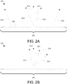
- Figure 2A is a side view drawing of the dissipation tape 101.
- the dissipation tape 101 comprises dissipation ridges 103 that dissipate the infrared radiation 315 at a dissipation angle 317.
- the dissipation angle 317 may be measured from a normal axis 313 for the dissipation tape 101.
- the dissipation angle 317 may be in the range of 5 to 35 degrees from the normal axis 313 for the dissipation tape 101.
- the dissipation angle 317 is a minimum dissipation angle 317.
- the dissipation angle 317 may increase from a center of the dissipation tape 101 towards an edge of the dissipation tape 101. In an alternate example, the dissipation angle 317 may increase from the edge of the dissipation tape 101 to the center of the dissipation tape 101.
- the dissipation angle 317 may direct the infrared radiation to a volume that more efficiently removes heat such as an area of air flow.
- the dissipation ridges 103 may be formed longitudinally along the dissipation tape 101. In one embodiment, the dissipation ridges 103 form a fresnel pattern.
- the dissipation tape 101 may have an infrared emissivity in the wavelength spectrum of 8 to 14 micrometers ( ⁇ m). In a certain embodiment, the dissipation ridges 103 have a thermal conductivity in the range of 5 to 20 degrees Celsius/Watt (°C/W).
- Figure 2B is a side view drawing of the dissipation tape 101.
- the dissipation tape 101 dissipates infrared radiation 315 at a dissipation vector 319 from the normal axis 313 for the dissipation table 101.
- the dissipation vector 319 may be an average of the vectors of infrared radiation 315 dissipating from the dissipation tape 110.
- the dissipation tape 101 may direct infrared radiation 315 at an average angle 321 from the normal axis 313.
- Figure 2C is a side view cross-section schematic drawing of the dissipation tape 101.
- the dissipation tape 101 is disposed on the busbar 111 and includes an adhesive material 107, a foil base 106, a base 105, and the dissipation ridges 103.
- the dissipation tape 101 includes a thermal coating 109.
- the cladding 113 includes a nano-paint layer 108 deposited on the busbar 111.
- the nano paint layer 108 may not be deposited on the busbar 111 under all of the dissipation tape 101. Only an overlap distance 219 of the nano paint layer 108 may be disposed between the cladding 113 and/or dissipation tape 101 and the busbar 111.
- the overlap distance 219 may be in the range of 50 to 500 millimeters (mm).
- the adhesive material 107 may have an adhesive thickness 211.
- the adhesive thickness 211 may be in the range of 25 to 100 ⁇ m. In one embodiment, the adhesive thickness 211 is 60 ⁇ m.
- the adhesive material 107 may be selected from the group consisting of acrylic adhesives and silicone adhesives. If the foil base 106 is a polyimide film, the adhesive material 107 may not be included.
- the foil base 106 may be selected from the group consisting of a polyimide film, an aluminum foil, and a copper foil.
- the polyimide film may be Kapton®.
- the foil base 106 may have a foil thickness 217 in the range of 25 to 100 ⁇ m.
- the foil thickness 217 may be in the range of 15 to 35 ⁇ m. In one embodiment, the foil thickness 217 for polyimide film is 25 ⁇ m.
- the foil thickness 217 for aluminum foil may be in the range of 80 to 120 ⁇ m.
- the foil thickness 217 for aluminum foil is 100 ⁇ m.
- the foil thickness 217 may be in the range of 80 to 120 ⁇ m.
- the foil thickness 217 for copper foil is 100 ⁇ m.
- An aluminum foil base 106 may be used with aluminum bus bars 111.
- a copper foil base 106 may be used with copper bus bars 111.
- the polyimide film may be punched, such as with a cold hammer.
- the aluminum foil and/or copper foil is skived.
- the aluminum foil and/or copper foil may be laser grooved.
- the dissipation ridges 103 may be formed with the base 105.
- a base ridge height 213 may be in the range of 80 to 150 ⁇ m. In one embodiment, the base ridge height 213 is 115 ⁇ m.
- a base height 203 may be in the range of 50 to 90 ⁇ m.
- the dissipation ridges 103 and base 105 may be metallic.
- the dissipation ridges 103 may have a ridge height 207 in the range of 30-60 ⁇ m and a ridge width 209 in the range of 50-90 ⁇ m.
- the dissipation ridges 103 may include a tape boundary 205.
- the tape boundary 205 may be in the range of 5 to 500 mm.
- the tape boundary 205 may be perpendicular to the normal axis 313. Alternatively, the tape boundary 205 may be sloped.
- the dissipation ridges 103 have a thermal coating 109.
- the thermal coating 109 may have a coating thickness 215 in the range of 4 to 10 ⁇ m.
- the thermal coating 109 may be black.
- Figure 2D is a perspective drawing of the dissipation tape 101.
- the dissipation tape 101 may be formed as a continuous segment.
- the dissipation tape 101 may be cut and applied to the busbar 111 to form the cladding 113.
- Figure 3A is a side view schematic drawing of dissipation tape 101.
- the particle coating 115 is shown deposited on the dissipation tape 101.
- the particle coating 115 comprises particles.
- the particles may be 50-70 percent by mass of silver and 30-50 percent by mass of copper, zinc, zinc oxide, gold, nickel, palladium, and/or aluminum.
- the particle coating 115 may be sintered to the dissipation tape 101.
- the particle coating 115 is sintered at a temperature in the range of 80 to 120 degrees C for a time in the range of 2 to 20 seconds.
- Figure 3B is a side view schematic drawing of a particle 305 of the particle coating 115.
- the particle 305 may have a particle dimension 307 in the range of 100 to 2500 nanometers (nm).
- a busbar 111 may carry significant current. As a result, the resistance of the busbar 111 may generate substantial heat. The heat must be dissipated from the busbar 111 to avoid damage to the busbar 111 and to improve the efficiency of the busbar 111 in distributing electrical power.
- the embodiments described herein include a cladding 113 with a dissipation tape 101 and a particle coating 115 deposited on the dissipation tape 101.
- the dissipation tape 101 may comprise dissipation ridges 103 that dissipate infrared radiation 315 at a dissipation angle 317.
- the dissipation angle 317 may be selected to dissipate the infrared radiation 315 more efficiently from the busbar 111.
- the dissipation tape 101 may include a particle coating 115 deposited on the dissipation tape 101.
- the particle coating 115 may further improve the efficiency of the cladding 113 in dissipating heat from the busbar 111.
Landscapes
- Engineering & Computer Science (AREA)
- Chemical & Material Sciences (AREA)
- Mechanical Engineering (AREA)
- Crystallography & Structural Chemistry (AREA)
- Physics & Mathematics (AREA)
- Thermal Sciences (AREA)
- General Engineering & Computer Science (AREA)
- Materials Engineering (AREA)
- Wood Science & Technology (AREA)
- Organic Chemistry (AREA)
- Life Sciences & Earth Sciences (AREA)
- Cooling Or The Like Of Semiconductors Or Solid State Devices (AREA)
- Cooling Or The Like Of Electrical Apparatus (AREA)
- Adhesive Tapes (AREA)
Abstract
Description
- The subject matter disclosed herein relates to a heat dissipating cladding.
- A cladding for dissipating heat is disclosed. The cladding includes a dissipation tape and a particle coating. The dissipation tape comprises dissipation ridges that dissipate infrared radiation at a dissipation angle. The particle coating is deposited on the dissipation tape.
- A system for dissipating heat is also disclosed. The system includes a busbar, dissipation tape, and a particle coating. The dissipation tape is disposed on the busbar and comprises dissipation ridges that dissipate infrared radiation at a dissipation angle. The particle coating is deposited on the dissipation tape.
- In order that the advantages of the embodiments of the invention will be readily understood, a more particular description of the embodiments briefly described above will be rendered by reference to specific embodiments that are illustrated in the appended drawings. Understanding that these drawings depict only some embodiments and are not therefore to be considered to be limiting of scope, the embodiments will be described and explained with additional specificity and detail through the use of the accompanying drawings, in which:
-
Figure 1 is a front view schematic drawing of busbar system according to an embodiment; -
Figure 2A is a side view drawing of dissipation tape according to an embodiment; -
Figure 2B is a side view drawing of dissipation tape according to an alternate embodiment; -
Figure 2C is a side view cross section schematic drawing of dissipation tape according to an embodiment; -
Figure 2D is a perspective drawing of the dissipation tape according to an embodiment; -
Figure 3A is a side view schematic drawing of dissipation tape with the particle coating according to an embodiment; and -
Figure 3B is a side view schematic drawing of a particle according to an embodiment. - Reference throughout this specification to "one embodiment," "an embodiment," or similar language means that a particular feature, structure, or characteristic described in connection with the embodiment is included in at least one embodiment. Thus, appearances of the phrases "in one embodiment," "in an embodiment," and similar language throughout this specification may, but do not necessarily, all refer to the same embodiment, but mean "one or more but not all embodiments" unless expressly specified otherwise. The terms "including," "comprising," "having," and variations thereof mean "including but not limited to" unless expressly specified otherwise. An enumerated listing of items does not imply that any or all of the items are mutually exclusive and/or mutually inclusive, unless expressly specified otherwise. The terms "a," "an," and "the" also refer to "one or more" unless expressly specified otherwise. The term "and/or" indicates embodiments of one or more of the listed elements, with "A and/or B" indicating embodiments of element A alone, element B alone, or elements A and B taken together.
- The description of elements in each figure may refer to elements of proceeding figures. Like numbers refer to like elements in all figures, including alternate embodiments of like elements.
-
Figure 1 is a front view schematic drawing ofbusbar system 100. Thebusbar system 100 may distribute electrical power within an equipment cabinet. In the depicted embodiment, thebusbar system 100 includes abusbar 111 and cladding 113 disposed on thebusbar 111. Thebusbar 111 may distribute high current electrical power. As a result, thebusbar 111 may generate significant heat. The heat may degrade the performance of thebusbar 111. - The embodiments provide cladding 113 that enhances heat dissipation from the
busbar 111. Thecladding 113 includes dissipation tape that dissipates infrared radiation at a dissipation angle to enhance the infrared radiation dissipation. In addition, thecladding 113 may include a particle coating deposited on the dissipation tape as will be described hereafter. As a result, an operating temperature of thebusbar 111 may be reduced and the efficiency and safety of thebusbar 111 may be enhanced. - The cladding 113 and/or
dissipation tape 101 may be applied to one side of thebusbar 111. In addition, the cladding 113 and/ordissipation tape 101 may be applied to two sides of thebusbar 111. In a certain embodiment, thecladding 113 and/ordissipation tape 101 is applied to each surface of thebusbar 111. -
Figure 2A is a side view drawing of thedissipation tape 101. In the depicted embodiment, thedissipation tape 101 comprisesdissipation ridges 103 that dissipate theinfrared radiation 315 at adissipation angle 317. Thedissipation angle 317 may be measured from anormal axis 313 for thedissipation tape 101. Thedissipation angle 317 may be in the range of 5 to 35 degrees from thenormal axis 313 for thedissipation tape 101. In a certain embodiment, thedissipation angle 317 is aminimum dissipation angle 317. For example, thedissipation angle 317 may increase from a center of thedissipation tape 101 towards an edge of thedissipation tape 101. In an alternate example, thedissipation angle 317 may increase from the edge of thedissipation tape 101 to the center of thedissipation tape 101. - By dissipating the infrared radiation at the
dissipation angle 317, heat may be more efficiently radiated from thebusbar 111. For example, thedissipation angle 317 may direct the infrared radiation to a volume that more efficiently removes heat such as an area of air flow. - The
dissipation ridges 103 may be formed longitudinally along thedissipation tape 101. In one embodiment, thedissipation ridges 103 form a fresnel pattern. Thedissipation tape 101 may have an infrared emissivity in the wavelength spectrum of 8 to 14 micrometers (µm). In a certain embodiment, thedissipation ridges 103 have a thermal conductivity in the range of 5 to 20 degrees Celsius/Watt (°C/W). -
Figure 2B is a side view drawing of thedissipation tape 101. In the depicted embodiment, thedissipation tape 101 dissipatesinfrared radiation 315 at adissipation vector 319 from thenormal axis 313 for the dissipation table 101. Thedissipation vector 319 may be an average of the vectors ofinfrared radiation 315 dissipating from the dissipation tape 110. As a result, thedissipation tape 101 may directinfrared radiation 315 at anaverage angle 321 from thenormal axis 313. -
Figure 2C is a side view cross-section schematic drawing of thedissipation tape 101. In the depicted embodiment, thedissipation tape 101 is disposed on thebusbar 111 and includes anadhesive material 107, afoil base 106, abase 105, and thedissipation ridges 103. In one embodiment, thedissipation tape 101 includes athermal coating 109. - In a certain embodiment, the
cladding 113 includes a nano-paint layer 108 deposited on thebusbar 111. Thenano paint layer 108 may not be deposited on thebusbar 111 under all of thedissipation tape 101. Only anoverlap distance 219 of thenano paint layer 108 may be disposed between thecladding 113 and/ordissipation tape 101 and thebusbar 111. Theoverlap distance 219 may be in the range of 50 to 500 millimeters (mm). - The
adhesive material 107 may have anadhesive thickness 211. Theadhesive thickness 211 may be in the range of 25 to 100 µm. In one embodiment, theadhesive thickness 211 is 60 µm. Theadhesive material 107 may be selected from the group consisting of acrylic adhesives and silicone adhesives. If thefoil base 106 is a polyimide film, theadhesive material 107 may not be included. - The
foil base 106 may be selected from the group consisting of a polyimide film, an aluminum foil, and a copper foil. The polyimide film may be Kapton®. Thefoil base 106 may have afoil thickness 217 in the range of 25 to 100 µm. For polyimide film, thefoil thickness 217 may be in the range of 15 to 35 µm. In one embodiment, thefoil thickness 217 for polyimide film is 25 µm. For aluminum foil, thefoil thickness 217 may be in the range of 80 to 120 µm. In a certain embodiment, thefoil thickness 217 for aluminum foil is 100 µm. For copper foil, thefoil thickness 217 may be in the range of 80 to 120 µm. In a certain embodiment, thefoil thickness 217 for copper foil is 100 µm. Analuminum foil base 106 may be used with aluminum bus bars 111. Acopper foil base 106 may be used with copper bus bars 111. - The polyimide film may be punched, such as with a cold hammer. In one embodiment, the aluminum foil and/or copper foil is skived. The aluminum foil and/or copper foil may be laser grooved.
- The
dissipation ridges 103 may be formed with thebase 105. Abase ridge height 213 may be in the range of 80 to 150 µm. In one embodiment, thebase ridge height 213 is 115 µm. Abase height 203 may be in the range of 50 to 90 µm. Thedissipation ridges 103 andbase 105 may be metallic. Thedissipation ridges 103 may have aridge height 207 in the range of 30-60 µm and aridge width 209 in the range of 50-90 µm. - In one embodiment, the
dissipation ridges 103 may include atape boundary 205. Thetape boundary 205 may be in the range of 5 to 500 mm. Thetape boundary 205 may be perpendicular to thenormal axis 313. Alternatively, thetape boundary 205 may be sloped. - In one embodiment, the
dissipation ridges 103 have athermal coating 109. Thethermal coating 109 may have acoating thickness 215 in the range of 4 to 10 µm. Thethermal coating 109 may be black. -
Figure 2D is a perspective drawing of thedissipation tape 101. Thedissipation tape 101 may be formed as a continuous segment. Thedissipation tape 101 may be cut and applied to thebusbar 111 to form thecladding 113. -
Figure 3A is a side view schematic drawing ofdissipation tape 101. In the depicted embodiment, theparticle coating 115 is shown deposited on thedissipation tape 101. In one embodiment, theparticle coating 115 comprises particles. The particles may be 50-70 percent by mass of silver and 30-50 percent by mass of copper, zinc, zinc oxide, gold, nickel, palladium, and/or aluminum. Theparticle coating 115 may be sintered to thedissipation tape 101. In one embodiment, theparticle coating 115 is sintered at a temperature in the range of 80 to 120 degrees C for a time in the range of 2 to 20 seconds. -
Figure 3B is a side view schematic drawing of aparticle 305 of theparticle coating 115. Theparticle 305 may have aparticle dimension 307 in the range of 100 to 2500 nanometers (nm). - A
busbar 111 may carry significant current. As a result, the resistance of thebusbar 111 may generate substantial heat. The heat must be dissipated from thebusbar 111 to avoid damage to thebusbar 111 and to improve the efficiency of thebusbar 111 in distributing electrical power. - The embodiments described herein include a
cladding 113 with adissipation tape 101 and aparticle coating 115 deposited on thedissipation tape 101. Thedissipation tape 101 may comprisedissipation ridges 103 that dissipateinfrared radiation 315 at adissipation angle 317. Thedissipation angle 317 may be selected to dissipate theinfrared radiation 315 more efficiently from thebusbar 111. In addition, thedissipation tape 101 may include aparticle coating 115 deposited on thedissipation tape 101. Theparticle coating 115 may further improve the efficiency of thecladding 113 in dissipating heat from thebusbar 111. - This description uses examples to disclose the invention and also to enable any person skilled in the art to practice the invention, including making and using any devices or systems and performing any incorporated methods. The patentable scope of the invention is defined by the claims and may include other examples that occur to those skilled in the art. Such other examples are intended to be within the scope of the claims if they have structural elements that do not differ from the literal language of the claims, or if they include equivalent structural elements with insubstantial differences from the literal language of the claims.
Claims (15)
- A cladding comprising:a dissipation tape comprising dissipation ridges that dissipate infrared radiation at a dissipation angle; anda particle coating deposited on the dissipation tape.
- The cladding of claim 1, wherein at least one of:the dissipation tape has an infrared emissivity in the wavelength spectrum of 8 to 14 micrometers (µm);the dissipation angle is in the range of 5 to 35 degrees from a normal axis for the dissipation tape;the dissipation tape dissipates infrared radiation at a dissipation vector from a normal axis for the dissipation tape; andthe dissipation ridges form a fresnel pattern.
- The cladding of claim 1 or 2, wherein the dissipation ridges have a ridge height in the range of 30-60 µm and a ridge width in the range of 50-90 µm.
- The cladding of claim 3, wherein the dissipation ridges have a thermal conductivity in the range of 5 to 20 degrees Celsius/Watt (°C/W).
- The cladding of claim 3 or 4, wherein the dissipation ridges are formed with a base and a base ridge height is in the range of 80 to 150 µm.
- The cladding of claim 5, wherein the dissipation ridges and base are metallic.
- The cladding of one of claims 1 to 6, the cladding further comprising a foil base, where the foil base is selected from the group consisting of polyimide film, aluminum foil, and copper foil.
- The cladding of claim 7, wherein the foil base has a foil thickness in the range of 25 to 100 µm.
- The cladding of one of claims 1 to 8, the cladding further comprising a nano-paint layer deposited on a busbar, wherein an overlap distance of the nano-paint layer is disposed between the cladding and the busbar.
- The cladding of one of claims 1 to 9, wherein the dissipation ridges have a thermal coating with a coating thickness in the range of 4 to 10 µm.
- The cladding of claim 10, wherein the thermal coating is black.
- The cladding of one of claims 1 to 11, wherein at least one of:the dissipation tape comprises an adhesive material with an adhesive thickness in the range of 25 to 100 µm;the particle coating comprises particles with a particle dimension in the range of 100 to 2500 nanometers (nm); andthe particle coating comprises particles of 50-70 percent by mass of silver and 30-50 percent by mass of copper, zinc, zinc oxide, gold, nickel, palladium, and/or aluminum.
- The cladding of one of claims 1 to 12, wherein the particle coating is sintered at a temperature in the range of 80 to 120 degrees C for a time in the range of 2 to 20 seconds.
- A system comprising:a busbar;a dissipation tape disposed on the busbar and comprising dissipation ridges that dissipate infrared radiation at a dissipation angle; anda particle coating deposited on the dissipating tape.
- The system of claim 14, wherein the dissipation tape is applied to two sides of the busbar.
Applications Claiming Priority (1)
| Application Number | Priority Date | Filing Date | Title |
|---|---|---|---|
| US16/671,031 US10648751B1 (en) | 2019-10-31 | 2019-10-31 | Heat dissipating cladding |
Publications (2)
| Publication Number | Publication Date |
|---|---|
| EP3816569A1 true EP3816569A1 (en) | 2021-05-05 |
| EP3816569B1 EP3816569B1 (en) | 2023-09-13 |
Family
ID=70612689
Family Applications (1)
| Application Number | Title | Priority Date | Filing Date |
|---|---|---|---|
| EP20204814.6A Active EP3816569B1 (en) | 2019-10-31 | 2020-10-30 | Heat dissipating cladding |
Country Status (3)
| Country | Link |
|---|---|
| US (1) | US10648751B1 (en) |
| EP (1) | EP3816569B1 (en) |
| CN (1) | CN112751298B (en) |
Families Citing this family (2)
| Publication number | Priority date | Publication date | Assignee | Title |
|---|---|---|---|---|
| US12011057B2 (en) | 2020-01-13 | 2024-06-18 | Msa Technology, Llc | Safety helmet |
| CN112126285B (en) * | 2020-09-27 | 2025-03-11 | 严继光 | A coating for enhancing thermal radiation and its application, and a radiation heat exchange device using the coating |
Citations (5)
| Publication number | Priority date | Publication date | Assignee | Title |
|---|---|---|---|---|
| CN102938549A (en) * | 2012-11-29 | 2013-02-20 | 江苏金华厦电气有限公司 | Novel energy-saving bus duct with high heat dissipation performance |
| US20130043071A1 (en) * | 2011-08-17 | 2013-02-21 | General Electric Company | Thermal energy management component and system incorporating the same |
| US20160324031A1 (en) * | 2013-11-12 | 2016-11-03 | Jnc Corporation | Heat sink |
| JP2017139842A (en) * | 2016-02-01 | 2017-08-10 | 東洋アルミニウム株式会社 | Heat radiating member for solar cell module and solar cell module using the same |
| CN110216924A (en) * | 2019-05-31 | 2019-09-10 | 宁波瑞凌新能源科技有限公司 | A kind of recombination radiation refrigeration film |
Family Cites Families (12)
| Publication number | Priority date | Publication date | Assignee | Title |
|---|---|---|---|---|
| US3930113A (en) * | 1974-06-10 | 1975-12-30 | Massachusetts Inst Technology | High voltage overhead transmission line conductor with reduced wet weather corona noise and corona losses |
| US6531206B2 (en) * | 2001-02-07 | 2003-03-11 | 3M Innovative Properties Company | Microstructured surface film assembly for liquid acquisition and transport |
| JP2008141809A (en) * | 2006-11-30 | 2008-06-19 | Mitsubishi Electric Corp | Resin molded insulated conductor |
| FR2934709B1 (en) * | 2008-08-01 | 2010-09-10 | Commissariat Energie Atomique | THERMAL EXCHANGE STRUCTURE AND COOLING DEVICE HAVING SUCH A STRUCTURE. |
| US8983019B2 (en) * | 2010-08-31 | 2015-03-17 | Massachusetts Institute Of Technology | Superwetting surfaces for diminishing leidenfrost effect, methods of making and devices incorporating the same |
| CN102446578A (en) * | 2010-10-15 | 2012-05-09 | 常熟市通润开关厂有限公司 | Bus with heat radiation function |
| US8780559B2 (en) * | 2011-12-29 | 2014-07-15 | General Electric Company | Heat exchange assembly for use with electrical devices and methods of assembling an electrical device |
| US9577164B2 (en) * | 2013-08-30 | 2017-02-21 | Asahi Kasei E-Materials Corporation | Semiconductor light emitting device and optical film |
| CN203590662U (en) * | 2013-11-13 | 2014-05-07 | 昆山立茂国际贸易有限公司 | Electronic component cooling device |
| CN206113101U (en) * | 2016-09-14 | 2017-04-19 | 沈阳金晨伟业冷暖设备有限公司 | Hyperthermia radiation ware |
| CN207869492U (en) * | 2017-12-29 | 2018-09-14 | 东莞市天晖电子材料科技有限公司 | Graphene heat sink substrate |
| CN209710562U (en) * | 2018-12-04 | 2019-11-29 | 广东智科精创科技股份有限公司 | A kind of temperature uniforming heat radiation piece |
-
2019
- 2019-10-31 US US16/671,031 patent/US10648751B1/en active Active
-
2020
- 2020-10-29 CN CN202011179425.5A patent/CN112751298B/en not_active Expired - Fee Related
- 2020-10-30 EP EP20204814.6A patent/EP3816569B1/en active Active
Patent Citations (5)
| Publication number | Priority date | Publication date | Assignee | Title |
|---|---|---|---|---|
| US20130043071A1 (en) * | 2011-08-17 | 2013-02-21 | General Electric Company | Thermal energy management component and system incorporating the same |
| CN102938549A (en) * | 2012-11-29 | 2013-02-20 | 江苏金华厦电气有限公司 | Novel energy-saving bus duct with high heat dissipation performance |
| US20160324031A1 (en) * | 2013-11-12 | 2016-11-03 | Jnc Corporation | Heat sink |
| JP2017139842A (en) * | 2016-02-01 | 2017-08-10 | 東洋アルミニウム株式会社 | Heat radiating member for solar cell module and solar cell module using the same |
| CN110216924A (en) * | 2019-05-31 | 2019-09-10 | 宁波瑞凌新能源科技有限公司 | A kind of recombination radiation refrigeration film |
Also Published As
| Publication number | Publication date |
|---|---|
| CN112751298A (en) | 2021-05-04 |
| CN112751298B (en) | 2022-06-07 |
| US10648751B1 (en) | 2020-05-12 |
| EP3816569B1 (en) | 2023-09-13 |
Similar Documents
| Publication | Publication Date | Title |
|---|---|---|
| EP1754401B1 (en) | Heat spreader with controlled z-axis conductivity | |
| JP5384522B2 (en) | Heat sink and heat sink forming method using wedge locking system | |
| US20140374080A1 (en) | Compliant multilayered thermally-conductive interface assemblies | |
| US9301429B2 (en) | Thermal blocker for mobile device skin hot spot management | |
| JP6439149B2 (en) | Chip resistor | |
| US11107749B2 (en) | Heat dissipation fin structure and cooling structure for electric substrate using the same | |
| KR20180084095A (en) | Manufacturing method of heat radiator, electronic device, lighting device and radiator | |
| US9593894B2 (en) | Thermal interface material and related systems and methods | |
| US10648751B1 (en) | Heat dissipating cladding | |
| JP2003188323A (en) | Graphite sheet and method for producing the same | |
| EP4218375B1 (en) | Thermal-control system of a media-streaming device and associated media-streaming devices | |
| JP2001358482A (en) | Heat radiative module | |
| JP2015046557A (en) | Radiator | |
| JP2009099753A (en) | heatsink | |
| US20080186675A1 (en) | Heatsink apparatus | |
| CN217936328U (en) | Shielding case cooling system and electronic equipment | |
| JP7734526B2 (en) | cooling device | |
| CN210628295U (en) | Graphite heat dissipation film | |
| JP2010045325A (en) | Semiconductor device, and method for manufacturing semiconductor device | |
| WO2017115627A1 (en) | Inverter | |
| KR20180032582A (en) | Thermal diffusion structure and method for forming the same | |
| EP3157054B1 (en) | Apparatus for regulating the temperature of an electronic device in a housing, a method and an assembly | |
| US10383254B2 (en) | Electronic device | |
| CN111010852B (en) | Electronic device | |
| CN209896481U (en) | Electrical cabinet and electrical control device |
Legal Events
| Date | Code | Title | Description |
|---|---|---|---|
| PUAI | Public reference made under article 153(3) epc to a published international application that has entered the european phase |
Free format text: ORIGINAL CODE: 0009012 |
|
| STAA | Information on the status of an ep patent application or granted ep patent |
Free format text: STATUS: THE APPLICATION HAS BEEN PUBLISHED |
|
| AK | Designated contracting states |
Kind code of ref document: A1 Designated state(s): AL AT BE BG CH CY CZ DE DK EE ES FI FR GB GR HR HU IE IS IT LI LT LU LV MC MK MT NL NO PL PT RO RS SE SI SK SM TR |
|
| STAA | Information on the status of an ep patent application or granted ep patent |
Free format text: STATUS: REQUEST FOR EXAMINATION WAS MADE |
|
| 17P | Request for examination filed |
Effective date: 20211105 |
|
| RBV | Designated contracting states (corrected) |
Designated state(s): AL AT BE BG CH CY CZ DE DK EE ES FI FR GB GR HR HU IE IS IT LI LT LU LV MC MK MT NL NO PL PT RO RS SE SI SK SM TR |
|
| STAA | Information on the status of an ep patent application or granted ep patent |
Free format text: STATUS: EXAMINATION IS IN PROGRESS |
|
| 17Q | First examination report despatched |
Effective date: 20221214 |
|
| GRAP | Despatch of communication of intention to grant a patent |
Free format text: ORIGINAL CODE: EPIDOSNIGR1 |
|
| STAA | Information on the status of an ep patent application or granted ep patent |
Free format text: STATUS: GRANT OF PATENT IS INTENDED |
|
| INTG | Intention to grant announced |
Effective date: 20230605 |
|
| GRAS | Grant fee paid |
Free format text: ORIGINAL CODE: EPIDOSNIGR3 |
|
| GRAA | (expected) grant |
Free format text: ORIGINAL CODE: 0009210 |
|
| STAA | Information on the status of an ep patent application or granted ep patent |
Free format text: STATUS: THE PATENT HAS BEEN GRANTED |
|
| AK | Designated contracting states |
Kind code of ref document: B1 Designated state(s): AL AT BE BG CH CY CZ DE DK EE ES FI FR GB GR HR HU IE IS IT LI LT LU LV MC MK MT NL NO PL PT RO RS SE SI SK SM TR |
|
| REG | Reference to a national code |
Ref country code: CH Ref legal event code: EP |
|
| REG | Reference to a national code |
Ref country code: DE Ref legal event code: R096 Ref document number: 602020017548 Country of ref document: DE |
|
| REG | Reference to a national code |
Ref country code: IE Ref legal event code: FG4D |
|
| REG | Reference to a national code |
Ref country code: LT Ref legal event code: MG9D |
|
| REG | Reference to a national code |
Ref country code: NL Ref legal event code: MP Effective date: 20230913 |
|
| PG25 | Lapsed in a contracting state [announced via postgrant information from national office to epo] |
Ref country code: GR Free format text: LAPSE BECAUSE OF FAILURE TO SUBMIT A TRANSLATION OF THE DESCRIPTION OR TO PAY THE FEE WITHIN THE PRESCRIBED TIME-LIMIT Effective date: 20231214 |
|
| PG25 | Lapsed in a contracting state [announced via postgrant information from national office to epo] |
Ref country code: SE Free format text: LAPSE BECAUSE OF FAILURE TO SUBMIT A TRANSLATION OF THE DESCRIPTION OR TO PAY THE FEE WITHIN THE PRESCRIBED TIME-LIMIT Effective date: 20230913 Ref country code: RS Free format text: LAPSE BECAUSE OF FAILURE TO SUBMIT A TRANSLATION OF THE DESCRIPTION OR TO PAY THE FEE WITHIN THE PRESCRIBED TIME-LIMIT Effective date: 20230913 Ref country code: NO Free format text: LAPSE BECAUSE OF FAILURE TO SUBMIT A TRANSLATION OF THE DESCRIPTION OR TO PAY THE FEE WITHIN THE PRESCRIBED TIME-LIMIT Effective date: 20231213 Ref country code: LV Free format text: LAPSE BECAUSE OF FAILURE TO SUBMIT A TRANSLATION OF THE DESCRIPTION OR TO PAY THE FEE WITHIN THE PRESCRIBED TIME-LIMIT Effective date: 20230913 Ref country code: LT Free format text: LAPSE BECAUSE OF FAILURE TO SUBMIT A TRANSLATION OF THE DESCRIPTION OR TO PAY THE FEE WITHIN THE PRESCRIBED TIME-LIMIT Effective date: 20230913 Ref country code: HR Free format text: LAPSE BECAUSE OF FAILURE TO SUBMIT A TRANSLATION OF THE DESCRIPTION OR TO PAY THE FEE WITHIN THE PRESCRIBED TIME-LIMIT Effective date: 20230913 Ref country code: GR Free format text: LAPSE BECAUSE OF FAILURE TO SUBMIT A TRANSLATION OF THE DESCRIPTION OR TO PAY THE FEE WITHIN THE PRESCRIBED TIME-LIMIT Effective date: 20231214 Ref country code: FI Free format text: LAPSE BECAUSE OF FAILURE TO SUBMIT A TRANSLATION OF THE DESCRIPTION OR TO PAY THE FEE WITHIN THE PRESCRIBED TIME-LIMIT Effective date: 20230913 |
|
| REG | Reference to a national code |
Ref country code: AT Ref legal event code: MK05 Ref document number: 1611687 Country of ref document: AT Kind code of ref document: T Effective date: 20230913 |
|
| PG25 | Lapsed in a contracting state [announced via postgrant information from national office to epo] |
Ref country code: NL Free format text: LAPSE BECAUSE OF FAILURE TO SUBMIT A TRANSLATION OF THE DESCRIPTION OR TO PAY THE FEE WITHIN THE PRESCRIBED TIME-LIMIT Effective date: 20230913 |
|
| PG25 | Lapsed in a contracting state [announced via postgrant information from national office to epo] |
Ref country code: IS Free format text: LAPSE BECAUSE OF FAILURE TO SUBMIT A TRANSLATION OF THE DESCRIPTION OR TO PAY THE FEE WITHIN THE PRESCRIBED TIME-LIMIT Effective date: 20240113 |
|
| PG25 | Lapsed in a contracting state [announced via postgrant information from national office to epo] |
Ref country code: AT Free format text: LAPSE BECAUSE OF FAILURE TO SUBMIT A TRANSLATION OF THE DESCRIPTION OR TO PAY THE FEE WITHIN THE PRESCRIBED TIME-LIMIT Effective date: 20230913 |
|
| PG25 | Lapsed in a contracting state [announced via postgrant information from national office to epo] |
Ref country code: ES Free format text: LAPSE BECAUSE OF FAILURE TO SUBMIT A TRANSLATION OF THE DESCRIPTION OR TO PAY THE FEE WITHIN THE PRESCRIBED TIME-LIMIT Effective date: 20230913 |
|
| PG25 | Lapsed in a contracting state [announced via postgrant information from national office to epo] |
Ref country code: SM Free format text: LAPSE BECAUSE OF FAILURE TO SUBMIT A TRANSLATION OF THE DESCRIPTION OR TO PAY THE FEE WITHIN THE PRESCRIBED TIME-LIMIT Effective date: 20230913 Ref country code: RO Free format text: LAPSE BECAUSE OF FAILURE TO SUBMIT A TRANSLATION OF THE DESCRIPTION OR TO PAY THE FEE WITHIN THE PRESCRIBED TIME-LIMIT Effective date: 20230913 Ref country code: IS Free format text: LAPSE BECAUSE OF FAILURE TO SUBMIT A TRANSLATION OF THE DESCRIPTION OR TO PAY THE FEE WITHIN THE PRESCRIBED TIME-LIMIT Effective date: 20240113 Ref country code: ES Free format text: LAPSE BECAUSE OF FAILURE TO SUBMIT A TRANSLATION OF THE DESCRIPTION OR TO PAY THE FEE WITHIN THE PRESCRIBED TIME-LIMIT Effective date: 20230913 Ref country code: EE Free format text: LAPSE BECAUSE OF FAILURE TO SUBMIT A TRANSLATION OF THE DESCRIPTION OR TO PAY THE FEE WITHIN THE PRESCRIBED TIME-LIMIT Effective date: 20230913 Ref country code: CZ Free format text: LAPSE BECAUSE OF FAILURE TO SUBMIT A TRANSLATION OF THE DESCRIPTION OR TO PAY THE FEE WITHIN THE PRESCRIBED TIME-LIMIT Effective date: 20230913 Ref country code: AT Free format text: LAPSE BECAUSE OF FAILURE TO SUBMIT A TRANSLATION OF THE DESCRIPTION OR TO PAY THE FEE WITHIN THE PRESCRIBED TIME-LIMIT Effective date: 20230913 Ref country code: SK Free format text: LAPSE BECAUSE OF FAILURE TO SUBMIT A TRANSLATION OF THE DESCRIPTION OR TO PAY THE FEE WITHIN THE PRESCRIBED TIME-LIMIT Effective date: 20230913 Ref country code: PT Free format text: LAPSE BECAUSE OF FAILURE TO SUBMIT A TRANSLATION OF THE DESCRIPTION OR TO PAY THE FEE WITHIN THE PRESCRIBED TIME-LIMIT Effective date: 20240115 |
|
| PG25 | Lapsed in a contracting state [announced via postgrant information from national office to epo] |
Ref country code: PL Free format text: LAPSE BECAUSE OF FAILURE TO SUBMIT A TRANSLATION OF THE DESCRIPTION OR TO PAY THE FEE WITHIN THE PRESCRIBED TIME-LIMIT Effective date: 20230913 Ref country code: IT Free format text: LAPSE BECAUSE OF FAILURE TO SUBMIT A TRANSLATION OF THE DESCRIPTION OR TO PAY THE FEE WITHIN THE PRESCRIBED TIME-LIMIT Effective date: 20230913 |
|
| REG | Reference to a national code |
Ref country code: CH Ref legal event code: PL |
|
| REG | Reference to a national code |
Ref country code: DE Ref legal event code: R097 Ref document number: 602020017548 Country of ref document: DE |
|
| REG | Reference to a national code |
Ref country code: BE Ref legal event code: MM Effective date: 20231031 |
|
| PG25 | Lapsed in a contracting state [announced via postgrant information from national office to epo] |
Ref country code: LU Free format text: LAPSE BECAUSE OF NON-PAYMENT OF DUE FEES Effective date: 20231030 |
|
| PG25 | Lapsed in a contracting state [announced via postgrant information from national office to epo] |
Ref country code: LU Free format text: LAPSE BECAUSE OF NON-PAYMENT OF DUE FEES Effective date: 20231030 |
|
| PG25 | Lapsed in a contracting state [announced via postgrant information from national office to epo] |
Ref country code: MC Free format text: LAPSE BECAUSE OF FAILURE TO SUBMIT A TRANSLATION OF THE DESCRIPTION OR TO PAY THE FEE WITHIN THE PRESCRIBED TIME-LIMIT Effective date: 20230913 |
|
| PG25 | Lapsed in a contracting state [announced via postgrant information from national office to epo] |
Ref country code: DK Free format text: LAPSE BECAUSE OF FAILURE TO SUBMIT A TRANSLATION OF THE DESCRIPTION OR TO PAY THE FEE WITHIN THE PRESCRIBED TIME-LIMIT Effective date: 20230913 |
|
| PG25 | Lapsed in a contracting state [announced via postgrant information from national office to epo] |
Ref country code: CH Free format text: LAPSE BECAUSE OF NON-PAYMENT OF DUE FEES Effective date: 20231031 |
|
| PLBE | No opposition filed within time limit |
Free format text: ORIGINAL CODE: 0009261 |
|
| STAA | Information on the status of an ep patent application or granted ep patent |
Free format text: STATUS: NO OPPOSITION FILED WITHIN TIME LIMIT |
|
| PG25 | Lapsed in a contracting state [announced via postgrant information from national office to epo] |
Ref country code: MC Free format text: LAPSE BECAUSE OF FAILURE TO SUBMIT A TRANSLATION OF THE DESCRIPTION OR TO PAY THE FEE WITHIN THE PRESCRIBED TIME-LIMIT Effective date: 20230913 Ref country code: DK Free format text: LAPSE BECAUSE OF FAILURE TO SUBMIT A TRANSLATION OF THE DESCRIPTION OR TO PAY THE FEE WITHIN THE PRESCRIBED TIME-LIMIT Effective date: 20230913 Ref country code: CH Free format text: LAPSE BECAUSE OF NON-PAYMENT OF DUE FEES Effective date: 20231031 |
|
| 26N | No opposition filed |
Effective date: 20240614 |
|
| PG25 | Lapsed in a contracting state [announced via postgrant information from national office to epo] |
Ref country code: BE Free format text: LAPSE BECAUSE OF NON-PAYMENT OF DUE FEES Effective date: 20231031 |
|
| PG25 | Lapsed in a contracting state [announced via postgrant information from national office to epo] |
Ref country code: IE Free format text: LAPSE BECAUSE OF NON-PAYMENT OF DUE FEES Effective date: 20231030 |
|
| PG25 | Lapsed in a contracting state [announced via postgrant information from national office to epo] |
Ref country code: SI Free format text: LAPSE BECAUSE OF FAILURE TO SUBMIT A TRANSLATION OF THE DESCRIPTION OR TO PAY THE FEE WITHIN THE PRESCRIBED TIME-LIMIT Effective date: 20230913 |
|
| PG25 | Lapsed in a contracting state [announced via postgrant information from national office to epo] |
Ref country code: SI Free format text: LAPSE BECAUSE OF FAILURE TO SUBMIT A TRANSLATION OF THE DESCRIPTION OR TO PAY THE FEE WITHIN THE PRESCRIBED TIME-LIMIT Effective date: 20230913 Ref country code: IE Free format text: LAPSE BECAUSE OF NON-PAYMENT OF DUE FEES Effective date: 20231030 |
|
| PG25 | Lapsed in a contracting state [announced via postgrant information from national office to epo] |
Ref country code: BG Free format text: LAPSE BECAUSE OF FAILURE TO SUBMIT A TRANSLATION OF THE DESCRIPTION OR TO PAY THE FEE WITHIN THE PRESCRIBED TIME-LIMIT Effective date: 20230913 |
|
| PG25 | Lapsed in a contracting state [announced via postgrant information from national office to epo] |
Ref country code: BG Free format text: LAPSE BECAUSE OF FAILURE TO SUBMIT A TRANSLATION OF THE DESCRIPTION OR TO PAY THE FEE WITHIN THE PRESCRIBED TIME-LIMIT Effective date: 20230913 |
|
| PG25 | Lapsed in a contracting state [announced via postgrant information from national office to epo] |
Ref country code: CY Free format text: LAPSE BECAUSE OF FAILURE TO SUBMIT A TRANSLATION OF THE DESCRIPTION OR TO PAY THE FEE WITHIN THE PRESCRIBED TIME-LIMIT; INVALID AB INITIO Effective date: 20201030 |
|
| PG25 | Lapsed in a contracting state [announced via postgrant information from national office to epo] |
Ref country code: HU Free format text: LAPSE BECAUSE OF FAILURE TO SUBMIT A TRANSLATION OF THE DESCRIPTION OR TO PAY THE FEE WITHIN THE PRESCRIBED TIME-LIMIT; INVALID AB INITIO Effective date: 20201030 |
|
| PGFP | Annual fee paid to national office [announced via postgrant information from national office to epo] |
Ref country code: GB Payment date: 20250923 Year of fee payment: 6 |
|
| PGFP | Annual fee paid to national office [announced via postgrant information from national office to epo] |
Ref country code: FR Payment date: 20250923 Year of fee payment: 6 |
|
| PG25 | Lapsed in a contracting state [announced via postgrant information from national office to epo] |
Ref country code: TR Free format text: LAPSE BECAUSE OF FAILURE TO SUBMIT A TRANSLATION OF THE DESCRIPTION OR TO PAY THE FEE WITHIN THE PRESCRIBED TIME-LIMIT Effective date: 20230913 |
|
| PGFP | Annual fee paid to national office [announced via postgrant information from national office to epo] |
Ref country code: DE Payment date: 20250923 Year of fee payment: 6 |