JP5384522B2 - Heat sink and heat sink forming method using wedge locking system - Google Patents
Heat sink and heat sink forming method using wedge locking system Download PDFInfo
- Publication number
- JP5384522B2 JP5384522B2 JP2010540692A JP2010540692A JP5384522B2 JP 5384522 B2 JP5384522 B2 JP 5384522B2 JP 2010540692 A JP2010540692 A JP 2010540692A JP 2010540692 A JP2010540692 A JP 2010540692A JP 5384522 B2 JP5384522 B2 JP 5384522B2
- Authority
- JP
- Japan
- Prior art keywords
- tpg
- hole
- heat sink
- metal
- bushing
- Prior art date
- Legal status (The legal status is an assumption and is not a legal conclusion. Google has not performed a legal analysis and makes no representation as to the accuracy of the status listed.)
- Expired - Fee Related
Links
Images


Classifications
-
- F—MECHANICAL ENGINEERING; LIGHTING; HEATING; WEAPONS; BLASTING
- F28—HEAT EXCHANGE IN GENERAL
- F28F—DETAILS OF HEAT-EXCHANGE AND HEAT-TRANSFER APPARATUS, OF GENERAL APPLICATION
- F28F21/00—Constructions of heat-exchange apparatus characterised by the selection of particular materials
- F28F21/02—Constructions of heat-exchange apparatus characterised by the selection of particular materials of carbon, e.g. graphite
-
- F—MECHANICAL ENGINEERING; LIGHTING; HEATING; WEAPONS; BLASTING
- F28—HEAT EXCHANGE IN GENERAL
- F28F—DETAILS OF HEAT-EXCHANGE AND HEAT-TRANSFER APPARATUS, OF GENERAL APPLICATION
- F28F21/00—Constructions of heat-exchange apparatus characterised by the selection of particular materials
- F28F21/08—Constructions of heat-exchange apparatus characterised by the selection of particular materials of metal
- F28F21/081—Heat exchange elements made from metals or metal alloys
- F28F21/084—Heat exchange elements made from metals or metal alloys from aluminium or aluminium alloys
-
- F—MECHANICAL ENGINEERING; LIGHTING; HEATING; WEAPONS; BLASTING
- F28—HEAT EXCHANGE IN GENERAL
- F28F—DETAILS OF HEAT-EXCHANGE AND HEAT-TRANSFER APPARATUS, OF GENERAL APPLICATION
- F28F21/00—Constructions of heat-exchange apparatus characterised by the selection of particular materials
- F28F21/08—Constructions of heat-exchange apparatus characterised by the selection of particular materials of metal
- F28F21/081—Heat exchange elements made from metals or metal alloys
- F28F21/085—Heat exchange elements made from metals or metal alloys from copper or copper alloys
-
- F—MECHANICAL ENGINEERING; LIGHTING; HEATING; WEAPONS; BLASTING
- F28—HEAT EXCHANGE IN GENERAL
- F28F—DETAILS OF HEAT-EXCHANGE AND HEAT-TRANSFER APPARATUS, OF GENERAL APPLICATION
- F28F3/00—Plate-like or laminated elements; Assemblies of plate-like or laminated elements
- F28F3/02—Elements or assemblies thereof with means for increasing heat-transfer area, e.g. with fins, with recesses, with corrugations
-
- H—ELECTRICITY
- H01—ELECTRIC ELEMENTS
- H01L—SEMICONDUCTOR DEVICES NOT COVERED BY CLASS H10
- H01L21/00—Processes or apparatus adapted for the manufacture or treatment of semiconductor or solid state devices or of parts thereof
- H01L21/02—Manufacture or treatment of semiconductor devices or of parts thereof
- H01L21/04—Manufacture or treatment of semiconductor devices or of parts thereof the devices having at least one potential-jump barrier or surface barrier, e.g. PN junction, depletion layer or carrier concentration layer
- H01L21/48—Manufacture or treatment of parts, e.g. containers, prior to assembly of the devices, using processes not provided for in a single one of the subgroups H01L21/06 - H01L21/326
- H01L21/4814—Conductive parts
- H01L21/4871—Bases, plates or heatsinks
- H01L21/4882—Assembly of heatsink parts
-
- H—ELECTRICITY
- H01—ELECTRIC ELEMENTS
- H01L—SEMICONDUCTOR DEVICES NOT COVERED BY CLASS H10
- H01L23/00—Details of semiconductor or other solid state devices
- H01L23/34—Arrangements for cooling, heating, ventilating or temperature compensation ; Temperature sensing arrangements
- H01L23/36—Selection of materials, or shaping, to facilitate cooling or heating, e.g. heatsinks
- H01L23/367—Cooling facilitated by shape of device
-
- H—ELECTRICITY
- H01—ELECTRIC ELEMENTS
- H01L—SEMICONDUCTOR DEVICES NOT COVERED BY CLASS H10
- H01L23/00—Details of semiconductor or other solid state devices
- H01L23/34—Arrangements for cooling, heating, ventilating or temperature compensation ; Temperature sensing arrangements
- H01L23/36—Selection of materials, or shaping, to facilitate cooling or heating, e.g. heatsinks
- H01L23/373—Cooling facilitated by selection of materials for the device or materials for thermal expansion adaptation, e.g. carbon
-
- H—ELECTRICITY
- H01—ELECTRIC ELEMENTS
- H01L—SEMICONDUCTOR DEVICES NOT COVERED BY CLASS H10
- H01L23/00—Details of semiconductor or other solid state devices
- H01L23/34—Arrangements for cooling, heating, ventilating or temperature compensation ; Temperature sensing arrangements
- H01L23/40—Mountings or securing means for detachable cooling or heating arrangements ; fixed by friction, plugs or springs
- H01L23/4006—Mountings or securing means for detachable cooling or heating arrangements ; fixed by friction, plugs or springs with bolts or screws
- H01L2023/4037—Mountings or securing means for detachable cooling or heating arrangements ; fixed by friction, plugs or springs with bolts or screws characterised by thermal path or place of attachment of heatsink
- H01L2023/4068—Heatconductors between device and heatsink, e.g. compliant heat-spreaders, heat-conducting bands
-
- H—ELECTRICITY
- H01—ELECTRIC ELEMENTS
- H01L—SEMICONDUCTOR DEVICES NOT COVERED BY CLASS H10
- H01L23/00—Details of semiconductor or other solid state devices
- H01L23/34—Arrangements for cooling, heating, ventilating or temperature compensation ; Temperature sensing arrangements
- H01L23/40—Mountings or securing means for detachable cooling or heating arrangements ; fixed by friction, plugs or springs
- H01L23/4006—Mountings or securing means for detachable cooling or heating arrangements ; fixed by friction, plugs or springs with bolts or screws
- H01L2023/4075—Mechanical elements
-
- H—ELECTRICITY
- H01—ELECTRIC ELEMENTS
- H01L—SEMICONDUCTOR DEVICES NOT COVERED BY CLASS H10
- H01L2924/00—Indexing scheme for arrangements or methods for connecting or disconnecting semiconductor or solid-state bodies as covered by H01L24/00
- H01L2924/0001—Technical content checked by a classifier
- H01L2924/0002—Not covered by any one of groups H01L24/00, H01L24/00 and H01L2224/00
-
- H—ELECTRICITY
- H01—ELECTRIC ELEMENTS
- H01L—SEMICONDUCTOR DEVICES NOT COVERED BY CLASS H10
- H01L2924/00—Indexing scheme for arrangements or methods for connecting or disconnecting semiconductor or solid-state bodies as covered by H01L24/00
- H01L2924/30—Technical effects
- H01L2924/301—Electrical effects
- H01L2924/3011—Impedance
-
- Y—GENERAL TAGGING OF NEW TECHNOLOGICAL DEVELOPMENTS; GENERAL TAGGING OF CROSS-SECTIONAL TECHNOLOGIES SPANNING OVER SEVERAL SECTIONS OF THE IPC; TECHNICAL SUBJECTS COVERED BY FORMER USPC CROSS-REFERENCE ART COLLECTIONS [XRACs] AND DIGESTS
- Y10—TECHNICAL SUBJECTS COVERED BY FORMER USPC
- Y10T—TECHNICAL SUBJECTS COVERED BY FORMER US CLASSIFICATION
- Y10T29/00—Metal working
- Y10T29/49—Method of mechanical manufacture
- Y10T29/4935—Heat exchanger or boiler making
Description
本開示は、一般に、様々な用途のヒートシンクとして働くように金属材料に熱分解グラファイト(TPG)を固定する方法に関し、より具体的には、楔係止システムを用いてTPG要素を金属材料に取外し可能に固定して、ヒートシンクを形成する方法に関する。 The present disclosure relates generally to a method of securing pyrolytic graphite (TPG) to a metallic material to serve as a heat sink for various applications, and more specifically, using a wedge locking system to remove a TPG element from a metallic material. The present invention relates to a method of forming a heat sink that can be fixed.
現代の組込み型コンピュータシステムは、熱出力が非常に高い電気部品を、限られた容積環境内に収容している。典型的には、こうした部品の熱出力放散が増大しても、その容積は変わらず、したがって部品温度の管理が重要な課題となっている。従来、アルミニウムおよび/または銅などの高熱伝導性材料から構成された能動または受動ヒートシンクなどの様々な直接冷却技術を用いて、温度上昇を管理してきている。しかし、これらの材料は、比較的広い表面積が空気流に露出する場合にしか十分でなく、したがって、利用可能な総容積の大部分を占める物理的に大型のヒートシンク構造が必要となる。ヒートシンクの物理的サイズが増大するにつれて、熱をヒートシンク先端部に迅速に伝達し、それによって熱を空気流に露出させるという材料の能力が低下する。 Modern embedded computer systems house electrical components with very high heat output in a limited volume environment. Typically, as the heat output dissipation of these components increases, their volume does not change, and therefore component temperature management has become an important issue. Traditionally, various direct cooling techniques such as active or passive heat sinks constructed from highly thermally conductive materials such as aluminum and / or copper have been used to manage temperature rise. However, these materials are only sufficient when a relatively large surface area is exposed to the air stream, thus requiring a physically large heat sink structure that occupies the majority of the total available volume. As the physical size of the heat sink increases, the ability of the material to transfer heat quickly to the heat sink tip, thereby exposing the heat to the air stream, decreases.
熱分解グラファイト(TPG)は、従来の金属材料に比べて、単一(X−Y)平面でより優れた熱伝導を実現する能力を有することが判明している。さらに、TPGは、銅に比べて、全体的な伝導率が改善されることが判明している。近年では、拡散接合法を用いて、TPGをアルミニウム構造に埋め込む方法が開発されてきている。拡散接合法によって、TPG材料とアルミニウム構造との間で非常に良好な熱接触が得られるものの、TPG埋込み構造を形成するには、専用の設備が必要であり、工程に時間がかかるという点で限界を有し、その結果製品が高価になる。 Pyrolytic graphite (TPG) has been found to have the ability to achieve better heat conduction in a single (XY) plane compared to conventional metallic materials. Furthermore, TPG has been found to improve overall conductivity compared to copper. In recent years, a method of embedding TPG in an aluminum structure using a diffusion bonding method has been developed. Although the diffusion bonding method provides very good thermal contact between the TPG material and the aluminum structure, a dedicated facility is required to form the TPG embedded structure, and the process takes time. There are limitations that result in expensive products.
したがって、アルミニウム構造などの金属材料にTPGを固定して、金属熱伝導構造(すなわちヒートシンク)を形成して、X−Y平面において有効な熱伝導率を実現する、費用効果の高い製品を形成する方法が求められている。さらに、本方法は、容易に再現可能であり、数多くの様々な施設で数多くの様々な種類の設備を使用して実施できると有利である。 Thus, TPG is secured to a metal material such as an aluminum structure to form a metal thermal conduction structure (ie heat sink) to form a cost effective product that achieves effective thermal conductivity in the XY plane. There is a need for a method. Furthermore, it is advantageous if the method is easily reproducible and can be performed using a number of different types of equipment in a number of different facilities.
一態様では、ヒートシンクを形成する方法が提供される。本方法は、楔形表面を有する第1の側、および平坦表面を有する第2の側を有する少なくとも1つのTPG要素を形成すること、少なくとも1つのTPG要素上に、少なくとも1つのTPG要素の第1の側と相補的となる(complementary)ように構成された金属材料を積層すること、および金属材料を少なくとも1つのTPG要素に固定するために圧力を印加することを含む。 In one aspect, a method for forming a heat sink is provided. The method includes forming at least one TPG element having a first side having a wedge-shaped surface and a second side having a flat surface, the first of the at least one TPG element on the at least one TPG element. Laminating a metal material configured to be complementary to the side of the substrate and applying pressure to secure the metal material to the at least one TPG element.
別の態様では、ヒートシンクを形成する方法が提供される。本方法は、少なくとも1つの拡張可能なブッシュと相補的となるように構成され、少なくとも1つのTPG要素を貫通する少なくとも1つの孔を形成すること、少なくとも1つの拡張可能なブッシュよりも大きく構成され、金属材料を貫通する少なくとも1つの孔を形成すること、および締結具を用いて、少なくとも1つの拡張可能なブッシュを金属材料中の少なくとも1つの孔に嵌入させることを含む。 In another aspect, a method for forming a heat sink is provided. The method is configured to be complementary to at least one expandable bushing, is configured to form at least one hole through the at least one TPG element, and is larger than at least one expandable bushing. Forming at least one hole through the metal material, and using a fastener to fit at least one expandable bush into the at least one hole in the metal material.
さらに別の態様では、ヒートシンクが提供される。このヒートシンクは、楔形表面を有する第1の側、および平坦表面を有する第2の側を備える少なくとも1つのTPG要素を含む。さらに、このヒートシンクは、少なくとも1つのTPG要素の第1の側に結合された金属材料を含む。 In yet another aspect, a heat sink is provided. The heat sink includes at least one TPG element having a first side having a wedge-shaped surface and a second side having a flat surface. Furthermore, the heat sink includes a metallic material bonded to the first side of the at least one TPG element.
さらに別の態様では、ヒートシンクが提供される。このヒートシンクは、少なくとも1つの貫通した孔を有する第1の側を有する少なくとも1つのTPG要素と、少なくとも1つのTPG要素中の少なくとも1つの孔の内側表面に結合された金属材料とを備える。この少なくとも1つのTPG要素は、少なくとも1つの拡張可能なブッシングと相補的となるように構成される。 In yet another aspect, a heat sink is provided. The heat sink comprises at least one TPG element having a first side with at least one through-hole and a metallic material coupled to the inner surface of at least one hole in the at least one TPG element. The at least one TPG element is configured to be complementary to at least one expandable bushing.
本開示は、熱分解グラファイト(TPG)を金属材料に固定してヒートシンクを形成することに関する。本明細書では、「TPG」とは、黒鉛が熱伝導に最適な一方向に整列した任意の黒鉛ベース材料を指す。この材料は、典型的には「整列グラファイト(aligned graphite)」、「TPG」、および「高配向性熱分解グラファイト(Highly Oriented Pyrolytic Graphite)(HOPG)」と呼ばれる。TPG要素によって、ヒートシンクのX−Y平面における熱伝導率の改善が実現される。より具体的には、本開示で提供される、TPG要素を金属材料に固定する方法を使用することによって、コンピュータシステムなどの電気システムの使用時に生じる温度を、従来の熱対策に比べて約10℃以上下げることができることが判明している。こうした放熱の改善によって、同じ容積環境で電気システムの電力容量をほぼ倍増させることが可能となる。さらに、電力の増大によって、通常なら支持できなかったシステムを支持することができ、または、周囲温度がより高い環境で既存のシステムを使用することが可能となる。 The present disclosure relates to securing pyrolytic graphite (TPG) to a metallic material to form a heat sink. As used herein, “TPG” refers to any graphite-based material in which graphite is aligned in one direction optimal for heat conduction. This material is typically referred to as “aligned graphite”, “TPG”, and “Highly Oriented Pyrolytic Graphite (HOPG)”. With the TPG element, an improvement in the thermal conductivity in the XY plane of the heat sink is realized. More specifically, by using the method provided in this disclosure for securing a TPG element to a metallic material, the temperature generated during use of an electrical system, such as a computer system, is about 10 compared to conventional thermal countermeasures. It has been found that the temperature can be lowered by more than ℃. This improvement in heat dissipation makes it possible to almost double the power capacity of the electrical system in the same volumetric environment. In addition, increased power can support systems that would otherwise not be supported, or allow existing systems to be used in environments with higher ambient temperatures.
上記のように、TPGを金属材料に固定することによってヒートシンクを形成する。TPG要素は、当技術分野で既知であり、また、本明細書に記載の教示が手引きする任意の適切なTPG要素製造方法および/または設備を使用して得ることができる。さらに、TPG要素は、例えば、コネチカット州ウィルトン所在のMomentive Performance Material社などの製造業者から市販されているものを入手することができる。 As described above, the heat sink is formed by fixing the TPG to a metal material. TPG elements are known in the art and can be obtained using any suitable TPG element manufacturing method and / or equipment guided by the teachings described herein. Further, TPG elements can be obtained commercially, for example, from manufacturers such as Momentive Performance Material, Wilton, Connecticut.
より具体的には、本方法は、一般に、少なくとも1つの楔形TPG要素を形成することを含む。楔形TPG要素上に金属材料を積層し、この金属材料は、TPG要素の楔形表面側と相補的となるように構成する。金属材料を楔形TPG要素に固定するために圧力を印加する。 More specifically, the method generally includes forming at least one wedge-shaped TPG element. A metal material is laminated on the wedge-shaped TPG element, and the metal material is configured to be complementary to the wedge-shaped surface side of the TPG element. Pressure is applied to secure the metallic material to the wedge-shaped TPG element.
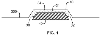
図1に示すように、TPG要素100は、楔形要素となるように構成される。より具体的には、楔形TPG要素100は、楔形表面を有する第1の側10と、平坦表面を有する第2の側12とを有するストリップを含む。図1に示すように、TPG要素100の第1の側10は、反対向きの第1の表面30と第2の表面32とが、中間表面34に対して約45度の角度でテーパが付いている。図1では反対向きの表面として示されているが、第1の表面30と、第2の表面32とは、本開示の範囲から逸脱することなく、互いに直接接触してもよいことを当業者には理解されたい。
As shown in FIG. 1, the
図2に示すように、特定の実施形態では、楔形TPG要素100は、第1の表面30のところ、またはその付近で、第2の表面32のところ、またはその付近の厚さとは異なる厚さを有する。限定するものではないが、図2に示すように、第1の表面30は、約0.060インチの厚さを有し、第2の表面32は、約0.050インチの厚さを有する。図2では異なる厚さを有するように示されているが、第1の表面30のところ、またはその付近の厚さは、本開示の範囲から逸脱することなく、第2の表面32のところ、またはその付近の厚さと同じでもよいことを当業者には理解されたい。楔形TPG要素100の厚さは、一方の表面30と、反対向きの表面32とで変える(または変えない)ことができるが、第1の表面30の幅と、第2の表面32の幅とは同じままとすることができることに留意されたい。さらに、第1の表面30は、第2の表面32よりも薄くてもよいことを理解されたい。また、2つ以上の表面(すなわち第1の表面30)を、本開示の範囲から逸脱することなく、楔形としてもよいことを理解されたい。
As shown in FIG. 2, in certain embodiments, the wedge-
要素100の1つまたは複数の寸法は変えることができるが、一実施形態の要素100は、約0.05インチ〜約0.06インチの厚さを有する。
Although one or more dimensions of the
本開示の方法で使用する少なくとも1つのTPG要素100を形成する。TPG要素100の寸法、TPG要素100の数、および/または隣接するTPG要素100間の間隔は、所望の最終製品に依存する。しかし、典型的には、2つ以上のTPG要素100を用いてヒートシンク(図3の500で示す)を形成することが適切である。
Form at least one
上記のように、本方法は、1つまたは複数のTPG要素100に金属材料300を積層することをさらに含む。金属材料300は、典型的には高い熱伝導率を有する材料から作成される。例えば、金属材料300は、アルミニウムおよび/または銅を含む。一実施形態では、金属材料300は、アルミニウムである。アルミニウムおよび銅はどちらも、ヒートシンクに使用すると、高い伝導率を示すことが示されてきている。より具体的には、アルミニウムは、ヒートシンクに使用すると、「Z」平面(図5に示す)において良好な熱伝導率を示す。しかし、上記のように、アルミニウムおよび銅だけでは、X−Y平面において十分な熱伝達が得られず、したがって、本開示では、TPGをアルミニウムおよび/または銅と組み合わせている。
As described above, the method further includes laminating the
一実施形態では、金属材料300は、TPG要素100の第1の側10と相補的となるように構成されている。より具体的には、図1に示すように、金属材料300をTPG要素100の第1の側10上に積層または配置する。この構成によって、係止固定システムが可能となり、その詳細を以下で説明する。
In one embodiment, the
一実施形態では、図3に示すように、金属材料300は、金属フィンアセンブリ302を含む。金属フィンアセンブリ302によって、熱伝導のためにより広い表面積が得られ、それによって、CPUなどの集積半導体回路などの熱源要素(図示せず)からの、より効率的かつ有効な放熱が促進される。特定の実施形態では、金属フィンアセンブリ302は、約6インチ×5インチ、厚さは約0.3インチである。一実施形態では、フィンアセンブリ302は、複数のフィン304を含み、これらのフィンはそれぞれ、高さが約0.24インチ、厚さが約0.024インチである。フィンアセンブリ302の隣接するフィン304間の間隔は、約0.096インチである。金属フィンアセンブリ302のフィン304は、本開示の範囲から逸脱することなく、上記以外のサイズおよび間隔とすることができることを当業者には理解されたい。
In one embodiment, as shown in FIG. 3, the
代替実施形態では、金属材料300は、空気ではなく、冷却壁に面した伝導冷却熱フレーム(図示せず)であり、この熱フレームは、その1つまたは複数の縁部に熱を伝達することを目的とする。伝導冷却熱フレームは、当技術分野で既知であり、ノースカロライナ州モーリスビル所在の製造業者Simon Industries社などから市販されているものなどでよい。
In an alternative embodiment, the
TPG要素100および金属材料300に加えて、いくつかの実施形態(図3および4に示すものなど)では、TPG要素100が、熱スペーサ400と、金属材料300との間に位置するような構成で、熱スペーサ400がTPG要素100(または、使用する場合にはストリップ保持プレート200)上に積層されている。熱スペーサ400を用いて、熱源要素(図示せず)をヒートシンク500に結合させる。さらに、熱スペーサ400は、熱を金属材料300の縁部に拡散させることが可能である。
In addition to the
典型的には、熱スペーサ400は、以下で説明するように、熱源要素と相補的となるように構成される。熱スペーサ400は、上述の金属材料300と同じ材料でも、または異なる材料でも作成することもできる。熱スペーサ400の作成に適した材料には、例えば、アルミニウムおよび/または銅を含めた金属材料が含まれる。一実施形態では、熱スペーサ400は、銅である。
Typically, the
上記のように、熱スペーサ400は、典型的には熱源要素と相補的となるように構成される。一般には、熱源要素は、集積半導体回路またはCPUなどの電気熱源要素である。上記のように、CPUなどの熱源要素の使用中、大量の熱が生じ、こうした熱は、熱源要素の過熱および/または誤動作を防止するために外部環境に放出しなければならない。例えば、集積回路では約30ワット以上の熱出力が放散されることがあり、ダイ温度は約100℃を超えるまでに達する。こうした熱は、集積回路の過熱を防止するために放出しなければならない。
As described above, the
図3および4に示すように、一実施形態では、積層後、TPG要素(複数可)100および金属材料300をストリップ保持プレート200に結合させる。より具体的には、図1に示す、TPG要素100の第2の側12の平坦表面を、平坦なストリップ保持プレート200に結合させる。例を挙げると、図3に示す一実施形態では、1つまたは複数のねじ120など、機械的結合手段を用いて、TPG要素100をストリップ保持プレート200に取り付ける。図3ではねじとして示されているが、TPG要素100は、当技術分野で既知の適切な任意の機械的結合手段を用いて、ストリップ保持プレート200に結合させることができることを当業者には理解されたい。
As shown in FIGS. 3 and 4, in one embodiment, after lamination, the TPG element (s) 100 and the
一般には、ストリップ保持プレート200は、TPG要素100を金属材料300に圧接するように力を加えるために設けられ、それによってTPG要素100と金属材料300との間の熱インターフェイスを最小限に抑え、さらに、ヒートシンク500に構造的支持および強度を加えるものである。
In general, the
典型的には、ストリップ保持プレート200は、アルミニウムおよび/または銅から作成される。一実施形態では、ストリップ保持プレート200は、アルミニウムから作成される。
Typically, the
一実施形態では、本開示の方法は、TPG要素100の第1の側10に、金属ベースのコーティング材料を付着させることを含む。より具体的には、使用する場合には、金属ベースのコーティング材料を、典型的にはTPG要素100の、金属材料300の方に面している第1の側10に付着させる。アルミニウム、銅、鉄、銀、金、ニッケル、亜鉛、錫、またはそれらの組合せなどの金属層を、TPG要素100の第1の側10に付着させる。特定の実施形態では、金属ベースのコーティング材料は、ニッケルで上塗りされる銅コーティング材料である。代替実施形態では、インジウムコーティングを、金属ベースのコーティング材料として使用している。
In one embodiment, the disclosed method includes depositing a metal-based coating material on the
金属ベースのコーティング材料によって、適切には機械的強度が得られる。金属ベースのコーティング材料は、典型的には厚さが少なくとも約0.001インチである。より適切には、金属ベースのコーティング材料は、約0.006インチ〜約0.025インチの厚さを有する。 The metal-based coating material suitably provides mechanical strength. Metal-based coating materials are typically at least about 0.001 inch thick. More suitably, the metal-based coating material has a thickness of about 0.006 inches to about 0.025 inches.
金属ベースのコーティング材料は、当技術分野で既知の適切な任意のパターンでTPG要素100の第1の側10に付着させることができる。例えば、一実施形態では、金属ベースのコーティング材料を、網目状(cross−hatched)パターンに付着させる。代替実施形態では、金属ベースのコーティング材料を線状(striped)パターンに付着させる。
The metal-based coating material can be applied to the
金属ベースのコーティング材料に加えて、一実施形態では、本方法は、TPG要素100の第1の側10に熱インターフェイス材料20を付着させることを含む。より具体的には、図1に示すように、その全体を20で示す熱インターフェイス材料を、適切には、金属材料300とTPG要素100との間に配設する。熱インターフェイス材料20によって、ヒートシンク500の2つの構成要素間、例えば、TPG要素100の第1の側10と、金属材料300との間の熱抵抗を低減させることが望まれる。適切な熱インターフェイス材料20の一例に、ミネソタ州チャンハッセン所在のBergquist社から市販されているBergquist TIC4000がある。
In addition to the metal-based coating material, in one embodiment, the method includes depositing a thermal interface material 20 on the
本開示の方法は、TPG要素100(および、使用する場合には保持プレート200)を金属材料300(および、使用する場合には熱スペーサ400)に固定して、ヒートシンク500を形成することを含む。適切には、TPG要素100および金属材料300を固定して、熱源要素から熱スペーサ400(使用する場合)へと、次いで、TPG要素100および金属材料300を介して周囲環境へと熱伝導を促進するように構成されたヒートシンク500を形成する。
The method of the present disclosure includes securing the TPG element 100 (and retaining
適切には、固定ステップは、楔係止金属材料300およびTPG要素ともに圧力を印加することを含む。圧力は、当技術分野で既知の適切な任意の手段を用いて印加することができる。圧力の量は、典型的には、使用する金属材料、およびともに係止させるTPG要素100の寸法および/または数に依存することになる。
Suitably, the securing step includes applying pressure with the wedge locking
上記のように、本開示の方法を用いて、TPG要素100を金属材料300に取外し可能に固定する。すなわち、本開示で使用する固定用楔係止システムによって、ヒートシンク500を便宜的かつ容易に分解し、組み立て直すことが可能となる。
As described above, the method of the present disclosure is used to removably secure the
代替の一実施形態では、熱伝導性接着剤(図示せず)をさらに用いて、TPG要素100を金属材料300に固定する。典型的には、TPG要素100および金属材料300、ならびに熱スペーサ400(使用する場合)の少なくとも一方に接着剤を付着させる。より具体的には、接着剤は、当技術分野で既知の任意の方法を用いて、ペーストまたはゲル状の形など、一般に半固体状態で付着させることができる。
In an alternative embodiment, a thermally conductive adhesive (not shown) is further used to secure the
一実施形態では、熱伝導性接着剤は、カリフォルニア州ビサリア所在のArctic Silver,Inc.社から市販されているArctic Silver Epoxyである。使用する接着剤の量は、典型的には、特定のヒートシンク構成に依存することになる。一実施形態では、シリンジおよびスパチュラを用いて接着剤約1.5mLを付着させ、TPG要素100、金属材料300、および熱スペーサ400上を覆う薄層となるように接着剤を塗り広げる。
In one embodiment, the thermally conductive adhesive is manufactured by Arcic Silver, Inc., Visalia, California. Arcic Silver Epoxy, commercially available from the company. The amount of adhesive used will typically depend on the particular heat sink configuration. In one embodiment, approximately 1.5 mL of adhesive is applied using a syringe and a spatula and spread to a thin layer over the
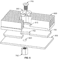
別の実施形態では、図6に示すように、少なくとも1つのTPG要素700が、拡張可能なブッシング900と相補的なサイズの少なくとも1つの孔750を含むように構成される。本明細書では、拡張可能なブッシング900は、当技術分野で既知の適切な任意の拡張可能なブッシングでよい。さらに、拡張可能なブッシング900を拡張させる特定の方法は、拡張可能なブッシング900を拡張させる、当技術分野で既知の任意の方法でよい。拡張可能なブッシング900のサイズおよび/または寸法は、典型的には、少なくとも1つの孔750のサイズ、ならびに特定のヒートシンクの構成および/または寸法に依存することになる。
In another embodiment, as shown in FIG. 6, at least one
さらに、金属材料600は、拡張可能なブッシング900が、その拡張時に、金属材料600ではなく、TPG要素700の内側表面に接して押し付けられるように、TPG要素700の孔750よりも十分大きくサイズ設定された少なくとも1つの孔610を含む。拡張可能なブッシング900の形状は、締結具740を中に嵌入させると、その外側表面が拡張するような形状である。一実施形態では、図6に示すように、テーパねじ740を、拡張可能なブッシング900を通して嵌入させる。さらに、テーパねじ740を、拡張可能なブッシング900を通し、テーパねじ740を受け入れられるほど十分大きい孔820を有する保持プレート800を通して、ナット742で受ける。テーパねじ740を締め付けると、拡張可能なブッシング900の外側表面(本明細書では壁とも呼ぶ)は拡張し、TPG要素700の内側表面に接して押し付けられ、それによって熱インターフェイスが減少する。
Further, the
一実施形態では、拡張可能なブッシング900の外側表面を、熱インターフェイス材料(図示せず)で被覆する。この熱インターフェイス材料は、拡張可能なブッシング900の外側表面の欠陥を塞いで、熱インピーダンスがより低い熱インターフェイスを形成する。一実施形態では、熱インターフェイス材料は、ミネソタ州チャンハッセン所在のBergquist社から市販されているTIC−4000であり、この熱インターフェイス材料を、拡張可能なブッシング900に線状パターンで付着させている。
In one embodiment, the outer surface of the
本発明を様々な特定の実施形態に関して説明してきたが、本発明は、特許請求の範囲の趣旨および範囲に含まれる改変形態でも実施できることが当業者には理解されよう。 While the invention has been described in terms of various specific embodiments, those skilled in the art will recognize that the invention can be practiced with modification within the spirit and scope of the claims.
10 第1の側
12 第2の側
20 熱インターフェイス材料
30 第1の表面
32 第2の表面
34 中間表面
100、700 TPG要素
200、800 ストリップ保持プレート
300、600 金属材料
302 金属フィンアセンブリ
304 フィン
400 熱スペーサ
500 ヒートシンク
610、750、820 孔
740 締結具(テーパねじ)
742 ナット
900 拡張可能なブッシング
DESCRIPTION OF
742
Claims (7)
前記TPG要素上に、金属フィンアセンブリを備えた金属材料を積層する工程と、
前記第1の孔よりも大きい第2の孔を前記金属材料に形成する工程と、
前記ブッシングを、前記金属材料中の前記第2の孔と、前記TPG要素中の前記第1の孔に嵌入させる工程と、
締結具を前記ブッシングに嵌入させる工程と、
前記締結具を締め付け、前記ブッシングを拡張させて、前記第1の孔内で前記ブッシングを前記TPG要素に押し付ける工程と、
を含み、
前記締結具が、前記第2の孔内で前記金属材料から隔てられており、前記締結具が前記金属材料を前記TPG要素に固定する、
ことを特徴とするヒートシンク形成方法。 Forming a first hole in the pyrolytic graphite (TPG) element , the first hole configured to be complementary to the bushing ;
On the T PG element, laminating a metal material having a metal fin assembly,
Forming a second hole larger than the first hole in the metal material;
Fitting the bushing into the second hole in the metallic material and the first hole in the TPG element;
Inserting a fastener into the bushing;
Tightening the fastener, expanding the bushing and pressing the bushing against the TPG element in the first hole;
Including
The fastener is separated from the metallic material in the second hole, and the fastener secures the metallic material to the TPG element;
The heat sink formation method characterized by the above-mentioned.
第3の孔を前記ストリップ保持プレートに形成する工程と、Forming a third hole in the strip retaining plate;
前記テーパねじを前記第3の孔に通す工程と、Passing the taper screw through the third hole;
前記テーパねじをナットで受けて締め付ける工程と、Receiving and tightening the taper screw with a nut;
含むことを特徴とする請求項6に記載の方法。The method of claim 6 comprising:
Applications Claiming Priority (3)
| Application Number | Priority Date | Filing Date | Title |
|---|---|---|---|
| US11/966,201 US8347502B2 (en) | 2007-12-28 | 2007-12-28 | Heat sink and method of forming a heatsink using a wedge-lock system |
| US11/966,201 | 2007-12-28 | ||
| PCT/US2008/083645 WO2009085423A2 (en) | 2007-12-28 | 2008-11-14 | A heat sink and method of forming a heatsink using a wedge-lock system |
Publications (3)
| Publication Number | Publication Date |
|---|---|
| JP2011508446A JP2011508446A (en) | 2011-03-10 |
| JP2011508446A5 JP2011508446A5 (en) | 2012-01-05 |
| JP5384522B2 true JP5384522B2 (en) | 2014-01-08 |
Family
ID=40328487
Family Applications (1)
| Application Number | Title | Priority Date | Filing Date |
|---|---|---|---|
| JP2010540692A Expired - Fee Related JP5384522B2 (en) | 2007-12-28 | 2008-11-14 | Heat sink and heat sink forming method using wedge locking system |
Country Status (6)
| Country | Link |
|---|---|
| US (2) | US8347502B2 (en) |
| EP (1) | EP2227822A2 (en) |
| JP (1) | JP5384522B2 (en) |
| KR (1) | KR20100110346A (en) |
| CN (1) | CN101911270B (en) |
| WO (1) | WO2009085423A2 (en) |
Families Citing this family (16)
| Publication number | Priority date | Publication date | Assignee | Title |
|---|---|---|---|---|
| US7740380B2 (en) * | 2008-10-29 | 2010-06-22 | Thrailkill John E | Solid state lighting apparatus utilizing axial thermal dissipation |
| US20110162828A1 (en) * | 2010-01-06 | 2011-07-07 | Graham Charles Kirk | Thermal plug for use with a heat sink and method of assembling same |
| US9096784B2 (en) | 2010-07-23 | 2015-08-04 | International Business Machines Corporation | Method and system for allignment of graphite nanofibers for enhanced thermal interface material performance |
| FR2967763B1 (en) * | 2010-11-19 | 2014-07-04 | Thales Sa | HEAT DISSIPATING DEVICE AND CORRESPONDING ELECTRONIC BOARD |
| CN102768998A (en) * | 2011-05-05 | 2012-11-07 | 优杰精密机械(苏州)有限公司 | Substrate for high-power electronic device module |
| US9111899B2 (en) | 2012-09-13 | 2015-08-18 | Lenovo | Horizontally and vertically aligned graphite nanofibers thermal interface material for use in chip stacks |
| US9245813B2 (en) | 2013-01-30 | 2016-01-26 | International Business Machines Corporation | Horizontally aligned graphite nanofibers in etched silicon wafer troughs for enhanced thermal performance |
| US9090004B2 (en) | 2013-02-06 | 2015-07-28 | International Business Machines Corporation | Composites comprised of aligned carbon fibers in chain-aligned polymer binder |
| US9082744B2 (en) | 2013-07-08 | 2015-07-14 | International Business Machines Corporation | Method for aligning carbon nanotubes containing magnetic nanoparticles in a thermosetting polymer using a magnetic field |
| NL2012119C2 (en) * | 2014-01-22 | 2015-07-23 | Dutch Space B V | Radiator, as well as space vehicle structure comprising such radiator. |
| US9426931B2 (en) | 2014-02-07 | 2016-08-23 | Lockheed Martin Corporation | Fluid-flow-through cooling of circuit boards |
| US9357670B2 (en) | 2014-02-18 | 2016-05-31 | Lockheed Martin Corporation | Efficient heat transfer from conduction-cooled circuit cards |
| US9953957B2 (en) | 2015-03-05 | 2018-04-24 | Invensas Corporation | Embedded graphite heat spreader for 3DIC |
| US20190016482A1 (en) * | 2015-03-12 | 2019-01-17 | Airbus Defence And Space Netherlands B.V. | Radiator, as well as space vehicle structure comprising such radiator |
| US10101099B2 (en) | 2015-03-12 | 2018-10-16 | Airbus Defence And Space Netherlands B.V. | Radiator, as well as space vehicle structure comprising such radiator |
| US11141823B2 (en) | 2018-04-28 | 2021-10-12 | Laird Technologies, Inc. | Systems and methods of applying materials to components |
Family Cites Families (33)
| Publication number | Priority date | Publication date | Assignee | Title |
|---|---|---|---|---|
| BE755639A (en) * | 1969-09-05 | 1971-03-02 | Amp Inc | CONNECTION FOR CIRCUIT PANEL PRINT |
| US4507034A (en) | 1982-10-01 | 1985-03-26 | Adjustable Bushing Corporation | Expandable bushing and lock fastener |
| EP0125683A3 (en) | 1983-05-19 | 1985-07-10 | Adjustable Bushing Corporation | An improved radially expandable bushing assembly |
| US5316080A (en) | 1990-03-30 | 1994-05-31 | The United States Of America As Represented By The Administrator Of The National Aeronautics & Space Administration | Heat transfer device |
| JPH0823183A (en) * | 1994-07-06 | 1996-01-23 | Matsushita Electric Ind Co Ltd | Structure of cooling member |
| US5969949A (en) | 1998-03-31 | 1999-10-19 | Sun Microsystems, Inc. | Interfitting heat sink and heat spreader slug |
| US5969950A (en) | 1998-11-04 | 1999-10-19 | Sun Microsystems, Inc. | Enhanced heat sink attachment |
| EP1187199A2 (en) | 2000-08-28 | 2002-03-13 | Alcan Technology & Management AG | Heatsink for Semiconductor Device, Method of Mannufacturing the same, as well as Molding Die therefore |
| US7219721B2 (en) | 2002-01-16 | 2007-05-22 | Fujitsu Limited | Heat sink having high efficiency cooling capacity and semiconductor device comprising it |
| US20030203181A1 (en) | 2002-04-29 | 2003-10-30 | International Business Machines Corporation | Interstitial material with enhanced thermal conductance for semiconductor device packaging |
| US8584738B2 (en) * | 2002-06-14 | 2013-11-19 | Lockheed Martin Corporation | Apparatus and method for extracting heat from a device |
| US6749010B2 (en) * | 2002-06-28 | 2004-06-15 | Advanced Energy Technology Inc. | Composite heat sink with metal base and graphite fins |
| US7416362B2 (en) | 2002-08-16 | 2008-08-26 | Siemens Power Generation, Inc. | Multidirectionally compliant fastening system |
| JP3948000B2 (en) | 2003-08-26 | 2007-07-25 | 松下電器産業株式会社 | High thermal conductivity member, method for manufacturing the same, and heat dissipation system using the same |
| US7220485B2 (en) | 2003-09-19 | 2007-05-22 | Momentive Performance Materials Inc. | Bulk high thermal conductivity feedstock and method of making thereof |
| US6903271B2 (en) * | 2003-09-30 | 2005-06-07 | Intel Corporation | Electronic assembly with thermally separated support |
| DE10353849B4 (en) | 2003-11-18 | 2009-05-07 | Infineon Technologies Ag | Pressing element for pressing an electrical pre-cooling part to be cooled against a cooling element, system for cooling an electrical component, and component arrangement with an electrical component to be cooled |
| US20100326645A1 (en) * | 2004-01-21 | 2010-12-30 | Wei Fan | Thermal pyrolytic graphite laminates with vias |
| US20070053168A1 (en) * | 2004-01-21 | 2007-03-08 | General Electric Company | Advanced heat sinks and thermal spreaders |
| US7288839B2 (en) | 2004-02-27 | 2007-10-30 | International Business Machines Corporation | Apparatus and methods for cooling semiconductor integrated circuit package structures |
| JP4430451B2 (en) * | 2004-04-21 | 2010-03-10 | 大成ラミネーター株式会社 | Semiconductor device heat dissipation device |
| TWI244370B (en) * | 2004-07-30 | 2005-11-21 | Ind Tech Res Inst | Bonding structure of heat sink fin and heat spreader |
| US7290596B2 (en) * | 2004-10-20 | 2007-11-06 | University Of Maryland | Thermal management of systems having localized regions of elevated heat flux |
| US7654311B2 (en) * | 2004-10-20 | 2010-02-02 | University Of Maryland | Thermal management of systems having localized regions of elevated heat flux |
| US20080248309A1 (en) * | 2004-11-09 | 2008-10-09 | Shimane Prefectural Government | Metal-Based Carbon Fiber Composite Material and Producing Method Thereof |
| US7567438B1 (en) * | 2005-06-14 | 2009-07-28 | Hewlett-Packard Development Company, L.P. | Heat sink with precompressed bias member |
| WO2006134858A1 (en) * | 2005-06-16 | 2006-12-21 | Matsushita Electric Industrial Co., Ltd. | Heat dissipating graphite sheet and electronic device using same |
| US20070188993A1 (en) | 2006-02-14 | 2007-08-16 | Gallina Mark J | Quasi-radial heatsink with rectangular form factor and uniform fin length |
| US7901509B2 (en) * | 2006-09-19 | 2011-03-08 | Momentive Performance Materials Inc. | Heating apparatus with enhanced thermal uniformity and method for making thereof |
| US8051896B2 (en) * | 2007-07-31 | 2011-11-08 | Adc Telecommunications, Inc. | Apparatus for spreading heat over a finned surface |
| US7539019B2 (en) * | 2007-07-31 | 2009-05-26 | Adc Telecommunications, Inc. | Apparatus for transferring heat from a heat spreader |
| US20090165302A1 (en) * | 2007-12-31 | 2009-07-02 | Slaton David S | Method of forming a heatsink |
| US7898807B2 (en) * | 2009-03-09 | 2011-03-01 | General Electric Company | Methods for making millichannel substrate, and cooling device and apparatus using the substrate |
-
2007
- 2007-12-28 US US11/966,201 patent/US8347502B2/en not_active Expired - Fee Related
-
2008
- 2008-11-14 CN CN2008801240236A patent/CN101911270B/en not_active Expired - Fee Related
- 2008-11-14 JP JP2010540692A patent/JP5384522B2/en not_active Expired - Fee Related
- 2008-11-14 KR KR1020107016840A patent/KR20100110346A/en not_active Application Discontinuation
- 2008-11-14 EP EP08867497A patent/EP2227822A2/en not_active Withdrawn
- 2008-11-14 WO PCT/US2008/083645 patent/WO2009085423A2/en active Application Filing
-
2012
- 2012-12-05 US US13/705,532 patent/US20130092363A1/en not_active Abandoned
Also Published As
| Publication number | Publication date |
|---|---|
| EP2227822A2 (en) | 2010-09-15 |
| CN101911270A (en) | 2010-12-08 |
| US8347502B2 (en) | 2013-01-08 |
| CN101911270B (en) | 2013-03-13 |
| US20090166021A1 (en) | 2009-07-02 |
| WO2009085423A3 (en) | 2009-10-08 |
| US20130092363A1 (en) | 2013-04-18 |
| KR20100110346A (en) | 2010-10-12 |
| WO2009085423A2 (en) | 2009-07-09 |
| JP2011508446A (en) | 2011-03-10 |
Similar Documents
| Publication | Publication Date | Title |
|---|---|---|
| JP5384522B2 (en) | Heat sink and heat sink forming method using wedge locking system | |
| US9222735B2 (en) | Compliant multilayered thermally-conductive interface assemblies | |
| US20100326645A1 (en) | Thermal pyrolytic graphite laminates with vias | |
| KR101385576B1 (en) | Compliant multilayered thermally-conductive interface assemblies and memory modules including the same | |
| EP2686163B1 (en) | High thermal conductivity/low coefficient of thermal expansion composites | |
| US20100321897A1 (en) | Compliant multilayered thermally-conductive interface assemblies | |
| JP2003188323A (en) | Graphite sheet and its manufacturing method | |
| US6131651A (en) | Flexible heat transfer device and method | |
| US20070053168A1 (en) | Advanced heat sinks and thermal spreaders | |
| US20150334871A1 (en) | Thermal interface materials with thin film sealants | |
| WO2007106653A2 (en) | Led with integral thermal via | |
| JP6432918B1 (en) | Circuit board housing | |
| JP2011508446A5 (en) | ||
| WO2016084751A1 (en) | Heat-dissipating structure and method for manufacturing same | |
| TWI700025B (en) | Multi-layer circuit board structure | |
| US10117355B2 (en) | Heat dissipation foil and methods of heat dissipation | |
| JP2012060127A (en) | Thermal interface material for reducing thermal resistance | |
| EP1025586B1 (en) | Flexible heat transfer device and method | |
| TWM540741U (en) | Multi-layer composite heat conduction structure | |
| CN112888238B (en) | Heat dissipation framework | |
| JP2003152371A (en) | Heat conductive material and manufacturing method thereof | |
| TWI391087B (en) | Expansion card assembly and heat sink thereof | |
| CN114144877A (en) | Thermal management of high heat flux multi-element assemblies |
Legal Events
| Date | Code | Title | Description |
|---|---|---|---|
| A521 | Written amendment |
Free format text: JAPANESE INTERMEDIATE CODE: A523 Effective date: 20111110 |
|
| A621 | Written request for application examination |
Free format text: JAPANESE INTERMEDIATE CODE: A621 Effective date: 20111110 |
|
| A521 | Written amendment |
Free format text: JAPANESE INTERMEDIATE CODE: A523 Effective date: 20121107 |
|
| A977 | Report on retrieval |
Free format text: JAPANESE INTERMEDIATE CODE: A971007 Effective date: 20130522 |
|
| A131 | Notification of reasons for refusal |
Free format text: JAPANESE INTERMEDIATE CODE: A131 Effective date: 20130611 |
|
| A521 | Written amendment |
Free format text: JAPANESE INTERMEDIATE CODE: A523 Effective date: 20130711 |
|
| TRDD | Decision of grant or rejection written | ||
| A01 | Written decision to grant a patent or to grant a registration (utility model) |
Free format text: JAPANESE INTERMEDIATE CODE: A01 Effective date: 20130910 |
|
| A61 | First payment of annual fees (during grant procedure) |
Free format text: JAPANESE INTERMEDIATE CODE: A61 Effective date: 20131002 |
|
| R150 | Certificate of patent or registration of utility model |
Free format text: JAPANESE INTERMEDIATE CODE: R150 |
|
| LAPS | Cancellation because of no payment of annual fees |