EP3816312A1 - Motor - Google Patents
Motor Download PDFInfo
- Publication number
- EP3816312A1 EP3816312A1 EP19804557.7A EP19804557A EP3816312A1 EP 3816312 A1 EP3816312 A1 EP 3816312A1 EP 19804557 A EP19804557 A EP 19804557A EP 3816312 A1 EP3816312 A1 EP 3816312A1
- Authority
- EP
- European Patent Office
- Prior art keywords
- motor
- steel sheet
- flux density
- equal
- magnetic flux
- Prior art date
- Legal status (The legal status is an assumption and is not a legal conclusion. Google has not performed a legal analysis and makes no representation as to the accuracy of the status listed.)
- Pending
Links
Images

Classifications
-
- C—CHEMISTRY; METALLURGY
- C22—METALLURGY; FERROUS OR NON-FERROUS ALLOYS; TREATMENT OF ALLOYS OR NON-FERROUS METALS
- C22C—ALLOYS
- C22C38/00—Ferrous alloys, e.g. steel alloys
- C22C38/02—Ferrous alloys, e.g. steel alloys containing silicon
-
- H—ELECTRICITY
- H01—ELECTRIC ELEMENTS
- H01F—MAGNETS; INDUCTANCES; TRANSFORMERS; SELECTION OF MATERIALS FOR THEIR MAGNETIC PROPERTIES
- H01F1/00—Magnets or magnetic bodies characterised by the magnetic materials therefor; Selection of materials for their magnetic properties
- H01F1/01—Magnets or magnetic bodies characterised by the magnetic materials therefor; Selection of materials for their magnetic properties of inorganic materials
- H01F1/03—Magnets or magnetic bodies characterised by the magnetic materials therefor; Selection of materials for their magnetic properties of inorganic materials characterised by their coercivity
- H01F1/12—Magnets or magnetic bodies characterised by the magnetic materials therefor; Selection of materials for their magnetic properties of inorganic materials characterised by their coercivity of soft-magnetic materials
- H01F1/14—Magnets or magnetic bodies characterised by the magnetic materials therefor; Selection of materials for their magnetic properties of inorganic materials characterised by their coercivity of soft-magnetic materials metals or alloys
- H01F1/147—Alloys characterised by their composition
-
- C—CHEMISTRY; METALLURGY
- C21—METALLURGY OF IRON
- C21D—MODIFYING THE PHYSICAL STRUCTURE OF FERROUS METALS; GENERAL DEVICES FOR HEAT TREATMENT OF FERROUS OR NON-FERROUS METALS OR ALLOYS; MAKING METAL MALLEABLE, e.g. BY DECARBURISATION OR TEMPERING
- C21D1/00—General methods or devices for heat treatment, e.g. annealing, hardening, quenching or tempering
- C21D1/26—Methods of annealing
- C21D1/30—Stress-relieving
-
- C—CHEMISTRY; METALLURGY
- C21—METALLURGY OF IRON
- C21D—MODIFYING THE PHYSICAL STRUCTURE OF FERROUS METALS; GENERAL DEVICES FOR HEAT TREATMENT OF FERROUS OR NON-FERROUS METALS OR ALLOYS; MAKING METAL MALLEABLE, e.g. BY DECARBURISATION OR TEMPERING
- C21D6/00—Heat treatment of ferrous alloys
- C21D6/008—Heat treatment of ferrous alloys containing Si
-
- C—CHEMISTRY; METALLURGY
- C21—METALLURGY OF IRON
- C21D—MODIFYING THE PHYSICAL STRUCTURE OF FERROUS METALS; GENERAL DEVICES FOR HEAT TREATMENT OF FERROUS OR NON-FERROUS METALS OR ALLOYS; MAKING METAL MALLEABLE, e.g. BY DECARBURISATION OR TEMPERING
- C21D8/00—Modifying the physical properties by deformation combined with, or followed by, heat treatment
- C21D8/12—Modifying the physical properties by deformation combined with, or followed by, heat treatment during manufacturing of articles with special electromagnetic properties
- C21D8/1216—Modifying the physical properties by deformation combined with, or followed by, heat treatment during manufacturing of articles with special electromagnetic properties the working step(s) being of interest
- C21D8/1222—Hot rolling
-
- C—CHEMISTRY; METALLURGY
- C21—METALLURGY OF IRON
- C21D—MODIFYING THE PHYSICAL STRUCTURE OF FERROUS METALS; GENERAL DEVICES FOR HEAT TREATMENT OF FERROUS OR NON-FERROUS METALS OR ALLOYS; MAKING METAL MALLEABLE, e.g. BY DECARBURISATION OR TEMPERING
- C21D8/00—Modifying the physical properties by deformation combined with, or followed by, heat treatment
- C21D8/12—Modifying the physical properties by deformation combined with, or followed by, heat treatment during manufacturing of articles with special electromagnetic properties
- C21D8/1216—Modifying the physical properties by deformation combined with, or followed by, heat treatment during manufacturing of articles with special electromagnetic properties the working step(s) being of interest
- C21D8/1233—Cold rolling
-
- C—CHEMISTRY; METALLURGY
- C21—METALLURGY OF IRON
- C21D—MODIFYING THE PHYSICAL STRUCTURE OF FERROUS METALS; GENERAL DEVICES FOR HEAT TREATMENT OF FERROUS OR NON-FERROUS METALS OR ALLOYS; MAKING METAL MALLEABLE, e.g. BY DECARBURISATION OR TEMPERING
- C21D8/00—Modifying the physical properties by deformation combined with, or followed by, heat treatment
- C21D8/12—Modifying the physical properties by deformation combined with, or followed by, heat treatment during manufacturing of articles with special electromagnetic properties
- C21D8/1244—Modifying the physical properties by deformation combined with, or followed by, heat treatment during manufacturing of articles with special electromagnetic properties the heat treatment(s) being of interest
- C21D8/1266—Modifying the physical properties by deformation combined with, or followed by, heat treatment during manufacturing of articles with special electromagnetic properties the heat treatment(s) being of interest between cold rolling steps
-
- C—CHEMISTRY; METALLURGY
- C21—METALLURGY OF IRON
- C21D—MODIFYING THE PHYSICAL STRUCTURE OF FERROUS METALS; GENERAL DEVICES FOR HEAT TREATMENT OF FERROUS OR NON-FERROUS METALS OR ALLOYS; MAKING METAL MALLEABLE, e.g. BY DECARBURISATION OR TEMPERING
- C21D9/00—Heat treatment, e.g. annealing, hardening, quenching or tempering, adapted for particular articles; Furnaces therefor
- C21D9/46—Heat treatment, e.g. annealing, hardening, quenching or tempering, adapted for particular articles; Furnaces therefor for sheet metals
-
- C—CHEMISTRY; METALLURGY
- C22—METALLURGY; FERROUS OR NON-FERROUS ALLOYS; TREATMENT OF ALLOYS OR NON-FERROUS METALS
- C22C—ALLOYS
- C22C38/00—Ferrous alloys, e.g. steel alloys
- C22C38/001—Ferrous alloys, e.g. steel alloys containing N
-
- C—CHEMISTRY; METALLURGY
- C22—METALLURGY; FERROUS OR NON-FERROUS ALLOYS; TREATMENT OF ALLOYS OR NON-FERROUS METALS
- C22C—ALLOYS
- C22C38/00—Ferrous alloys, e.g. steel alloys
- C22C38/002—Ferrous alloys, e.g. steel alloys containing In, Mg, or other elements not provided for in one single group C22C38/001 - C22C38/60
-
- C—CHEMISTRY; METALLURGY
- C22—METALLURGY; FERROUS OR NON-FERROUS ALLOYS; TREATMENT OF ALLOYS OR NON-FERROUS METALS
- C22C—ALLOYS
- C22C38/00—Ferrous alloys, e.g. steel alloys
- C22C38/008—Ferrous alloys, e.g. steel alloys containing tin
-
- C—CHEMISTRY; METALLURGY
- C22—METALLURGY; FERROUS OR NON-FERROUS ALLOYS; TREATMENT OF ALLOYS OR NON-FERROUS METALS
- C22C—ALLOYS
- C22C38/00—Ferrous alloys, e.g. steel alloys
- C22C38/04—Ferrous alloys, e.g. steel alloys containing manganese
-
- C—CHEMISTRY; METALLURGY
- C22—METALLURGY; FERROUS OR NON-FERROUS ALLOYS; TREATMENT OF ALLOYS OR NON-FERROUS METALS
- C22C—ALLOYS
- C22C38/00—Ferrous alloys, e.g. steel alloys
- C22C38/06—Ferrous alloys, e.g. steel alloys containing aluminium
-
- C—CHEMISTRY; METALLURGY
- C22—METALLURGY; FERROUS OR NON-FERROUS ALLOYS; TREATMENT OF ALLOYS OR NON-FERROUS METALS
- C22C—ALLOYS
- C22C38/00—Ferrous alloys, e.g. steel alloys
- C22C38/12—Ferrous alloys, e.g. steel alloys containing tungsten, tantalum, molybdenum, vanadium, or niobium
-
- C—CHEMISTRY; METALLURGY
- C22—METALLURGY; FERROUS OR NON-FERROUS ALLOYS; TREATMENT OF ALLOYS OR NON-FERROUS METALS
- C22C—ALLOYS
- C22C38/00—Ferrous alloys, e.g. steel alloys
- C22C38/60—Ferrous alloys, e.g. steel alloys containing lead, selenium, tellurium, or antimony, or more than 0.04% by weight of sulfur
-
- H—ELECTRICITY
- H01—ELECTRIC ELEMENTS
- H01F—MAGNETS; INDUCTANCES; TRANSFORMERS; SELECTION OF MATERIALS FOR THEIR MAGNETIC PROPERTIES
- H01F1/00—Magnets or magnetic bodies characterised by the magnetic materials therefor; Selection of materials for their magnetic properties
- H01F1/01—Magnets or magnetic bodies characterised by the magnetic materials therefor; Selection of materials for their magnetic properties of inorganic materials
- H01F1/03—Magnets or magnetic bodies characterised by the magnetic materials therefor; Selection of materials for their magnetic properties of inorganic materials characterised by their coercivity
- H01F1/12—Magnets or magnetic bodies characterised by the magnetic materials therefor; Selection of materials for their magnetic properties of inorganic materials characterised by their coercivity of soft-magnetic materials
- H01F1/14—Magnets or magnetic bodies characterised by the magnetic materials therefor; Selection of materials for their magnetic properties of inorganic materials characterised by their coercivity of soft-magnetic materials metals or alloys
- H01F1/147—Alloys characterised by their composition
- H01F1/14766—Fe-Si based alloys
- H01F1/14775—Fe-Si based alloys in the form of sheets
-
- H—ELECTRICITY
- H01—ELECTRIC ELEMENTS
- H01F—MAGNETS; INDUCTANCES; TRANSFORMERS; SELECTION OF MATERIALS FOR THEIR MAGNETIC PROPERTIES
- H01F3/00—Cores, Yokes, or armatures
- H01F3/02—Cores, Yokes, or armatures made from sheets
-
- H—ELECTRICITY
- H02—GENERATION; CONVERSION OR DISTRIBUTION OF ELECTRIC POWER
- H02K—DYNAMO-ELECTRIC MACHINES
- H02K1/00—Details of the magnetic circuit
- H02K1/02—Details of the magnetic circuit characterised by the magnetic material
-
- H—ELECTRICITY
- H02—GENERATION; CONVERSION OR DISTRIBUTION OF ELECTRIC POWER
- H02K—DYNAMO-ELECTRIC MACHINES
- H02K2213/00—Specific aspects, not otherwise provided for and not covered by codes H02K2201/00 - H02K2211/00
- H02K2213/03—Machines characterised by numerical values, ranges, mathematical expressions or similar information
-
- Y—GENERAL TAGGING OF NEW TECHNOLOGICAL DEVELOPMENTS; GENERAL TAGGING OF CROSS-SECTIONAL TECHNOLOGIES SPANNING OVER SEVERAL SECTIONS OF THE IPC; TECHNICAL SUBJECTS COVERED BY FORMER USPC CROSS-REFERENCE ART COLLECTIONS [XRACs] AND DIGESTS
- Y02—TECHNOLOGIES OR APPLICATIONS FOR MITIGATION OR ADAPTATION AGAINST CLIMATE CHANGE
- Y02T—CLIMATE CHANGE MITIGATION TECHNOLOGIES RELATED TO TRANSPORTATION
- Y02T10/00—Road transport of goods or passengers
- Y02T10/60—Other road transportation technologies with climate change mitigation effect
- Y02T10/64—Electric machine technologies in electromobility
Abstract
Description
- The present invention relates to a motor that is suitable for cordless home appliances, cutting tools, and drones, and is driven at high speed.
- Product value of apparatuses using a battery as a power supply, such as cordless home appliances (for example, a vacuum cleaner), cutting tools, and drones, frequently depend on their usable time and weight. It is therefore highly demanded to increase the efficiency by reducing loss in the control system such as a motor and an inverter, and to achieve downsizing and higher speed rotation of the motor. Motors are thus designed to have the minimum body size and to be able to output the maximum power at the highest efficiency depending on the usage. On the other hand, motors are required to be driven not only at a rotational speed for the maximum output (maximum output speed), but also under conditions of a lower output speed and a lower output. Under such driving conditions, the iron core is excited by the magnet to a level that is not necessarily required, which compromises the efficiency of the motor. Against this background, to reduce the iron loss in the motor when driving under conditions other than the maximum output, in some driving conditions, control is conducted on the motor to intentionally weaken the excitation magnetic flux density of the iron core by current phase advance control. This type of motor is designed to be smaller and lighter and thus to rotate at high speed. The excitation frequency of the iron core is therefore high such as one to several kilo-Hertz. Iron cores for specific purposes are made of permendur and other materials. Since such materials are quite expensive, non-oriented electrical steel sheets are widely used for iron cores.
- The loss caused in the iron core is classed into the hysteresis loss and the eddy-current loss. As is known, the eddy current loss becomes dominant with an increase in the excitation frequency. As measures taken to reduce the eddy-current losses, for example, the specific resistance of the steel sheet may be increased by adding a non-magnetic element such as Si or Al, or the thickness of the sheet may be reduced. Unfortunately, increasing the content of alloy made of non-magnetic elements reduces the value of magnetic saturation of the steel sheet. To reduce the iron loss at high frequencies while keeping the magnetic flux density high,
Patent Literature 1 describes use of Si gradient steel that has the concentration gradient of Si controlled in the sheet thickness direction. - Patent Literature 1: Japanese Patent No.
4677955 - Use of the Si gradient steel for a material of the iron core of an electric apparatus, having an excitation frequency of several kilo-Hertz, can reduce the eddy-current losses; however, this method is not sufficiently effective to reduce the loss in a motor in which the above-described current phase advance control is employed with the intention to reduce the loss in the motor iron core. This is a critical issue especially for a reduced-size high-speed motor that is designed to be fed with power from the battery. For controlling the magnetic flux density of the iron core using the current phase advance control, a large magnetizing force is necessary. In other words, it is necessary to apply a large current to the magnet wire or to increase the number of windings of the coil. An increase in the current increases the copper loss, the loss in the magnet wire, which reduces the efficiency of the motor. An increase in the number of windings of the coil increases the counter electromotive voltage generated by a rotor magnet of the motor, which makes it more difficult to drive the motor at high rotational speed. As described above, a motor that achieves high efficiency, downsizing, and high speed under limited power conditions has problems to be solved, and above all, an iron core material suitable for such a motor is yet to be found.
- The present invention is made in view of the above problems. An object of the present invention is to provide a motor capable of achieving higher efficiency, downsizing, and higher speed by reducing the iron loss during drive at a rotational speed lower than the maximum rotational speed.
- To solve the above problems, the inventors of the present invention have conducted earnest studies on iron core materials having electrical characteristics suitable for high-speed motor. As a result, it has been found out that iron core materials having not only a low iron loss but also having a sharp change in a magnetic flux density to a change in a magnetic field is effective for achieving higher efficiency, downsizing, and higher speed of a motor. In the present specification, "high-speed motor" means a motor whose maximum frequency of basic component of excitation condition of iron core, is over 1000 Hz.
- To solve the problem and achieve the object, a motor according to the present invention that is able to perform motor drive control that weakens a magnetic flux density of an iron core during drive at a rotational speed lower than a maximum rotational speed. The motor includes a steel sheet used as a core material of the motor, wherein the steel sheet includes a composition including: by mass%, 0.010% or less of C; 2.0% to 7.0% of Si; 2.0% or less of Al; 0.05% to 1.0% of Mn; 0.005% or less of S; 0.005% or less of N; and balance Fe and inevitable impurities; the steel sheet includes a magnetic flux density changing area where a change ΔB in magnetic flux density to a change ΔH = 50 A/m in a magnetic field, is equal to or higher than 0.50 T; a thickness of the steel sheet is 0.05 mm to 0.20 mm; and an eddy-current loss of the steel sheet, at 1000 Hz - 1.0 T, is equal to or less than 0.55 of a total iron loss.
- Moreover, in the motor according to the present invention, the steel sheet further includes: by mass%, at least one element selected from 0.01% to 0.1% of P; 0.001% to 0.1% of Sn; 0.001% to 0.1% of Sb; and 0.001% to 0.01% of Mo.
- Moreover, in the motor according to the present invention, a difference between a concentration of Si at a surface of the steel sheet and a concentration of Si at a center portion of the steel sheet is 0.5% to 4.0%, and a saturation magnetic flux density Bs of the steel sheet is equal to or higher than 2.0 T.
- Moreover, in the motor according to the present invention, the magnetic flux density changing area is present in an area including a magnetic flux density equal to or higher than 1 T.
- According to the present invention, it is possible to provide a motor capable of achieving higher efficiency, downsizing, and higher speed by reducing the iron loss during drive at a rotational speed lower than the maximum rotational speed.
-
-
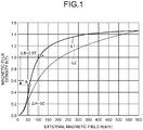
FIG. 1 is an example graph of the magnetic flux density versus the external magnetic field of a steel sheet. -
FIG. 2 is a schematic drawing that illustrates an example configuration of a two-pole three-phase brushless DC motor. - Requirements of a steel sheet, used as a material of the iron core of a motor according to the present invention, and reasons for the limitation will now be described. There is no limitation, other than being a magnetic motor, on the type of motor according to the present invention. In the following description, added components simply indicated in "percentage" are actually in "percentage by mass".
- Since excessively adding carbon (C) to a steel sheet increases the hysteresis losses in the motor, the content of C should be equal to or less than 0.010%.
- Silicon (Si) is an additive element effective for reducing the eddy-current losses in the motor by increasing the specific resistance of the steel sheet. Too much Si added to a steel sheet, however, makes the processing into a motor iron core more difficult and reduces the saturation magnetic flux density of the steel sheet. The content of Si should therefore be from 2.0% to 7.0%. Since adding Si equal to or higher than 4.0% impairs the rollability of the steel sheet, for example, Si may be added after cold rolling using the chemical vapor siliconizing method. More specifically, Si may be added such that the concentration difference of Si between the center layer and the surface layer of the steel sheet is in the range from 0.5% to 4.0% and that the saturation magnetic flux density Bs is equal to or higher than 2.0 T. This manner is advantageous in reducing the size of the motor while reducing the eddy-current losses.
- Aluminum (Al) and manganese (Mn) are elements effective for reducing the eddy-current losses in a motor by increasing the specific resistance of the steel sheet. Excessive addition of Al and Mn, however, negatively affects the grain growth and increases the hysteresis losses in the motor. The content of Al should therefore be equal to or less than 2.0%, and the content of Mn should be in the range from 0.05% to 1.0%.
- Excessive addition of S and N causes generation of precipitates and inhibits the grain growth and increases the hysteresis losses in the motor. The content of each S and N is therefore equal to or less than 0.005%, and the balance is Fe and unavoidable impurities.
- At least one of elements selected from P: from 0.01% to 0.1%, Sn: from 0.001% to 0.1%, Sb: from 0.001% to 0.1%, and Mo: from 0.001% to 0.01%
- To the above composition, containing at least one of elements selected from P: from 0.01% to 0.1%, Sn: from 0.001% to 0.1%, Sb: from 0.001% to 0.1%, and Mo: from 0.001% to 0.01% can improve the magnetic flux density of the steel sheet. It is therefore preferable to add the selected element. However, excessive addition of whatever the element impairs productivity and magnetic characteristics of the steel sheet.
- Change ΔB in magnetic flux density to change ΔH = 50 A/m in magnetic field being equal to or higher than 0.50 T
- A steel sheet subjected to a sharp change ΔB in the magnetic flux density equal to or higher than 0.50 T to a change ΔH = 50 A/m in the magnetic field enables easy control of the magnetic flux density of the motor in the event of drive that is powered by a battery and has limited conditions on the power supply (the voltage, the current, or both of them).
- For example,
FIG. 1 is an example graph of the magnetic flux density B versus the external magnetic field H of a steel sheet. In an example of the invention (a curve L1), a change ΔB in the magnetic flux density B is equal to or higher than 0.50 T to a change ΔH = 50 A/m in the external magnetic field H from a point A to a point B. In a comparative example (a curve L2), there is no areas that includes a change ΔB in the magnetic flux density B equal to or higher than 0.50 T to a change ΔH = 50 A/m in the external magnetic field H. In the example of the invention, for example, if the excitation magnetic flux density in use of a magnet is designed to a value around the point A, a magnetizing force of 50 A/m is necessary for a current control to weaken the magnetic flux density of the iron core to the level of the point B. In the comparative example, a magnetizing force of 140 A/m is necessary to weaken the magnetic flux density of the iron core from the level of the point A to the level of the point B. With power supply under limited conditions, however, such a strong magnetizing force is actually unavailable. It is therefore difficult to weaken the magnetic flux density, and the current control cannot effectively reduce the iron loss in the motor. - The steel sheet used as a material of the iron core of a motor according to the present invention therefore has an area having a sharp change in the magnetic flux density where a change ΔB in magnetic flux density is equal to or higher than 0.50 T to a change ΔH = 50A/m in the magnetic field. Furthermore, if this area having a sharp change in the magnetic flux density is present in the area including the magnetic flux density equal to or higher than 1 T, the magnetic flux density of the iron core is maintained high with the above-described current control being effectively conducted. Downsizing of the motor is therefore achieved.
- Although reducing the thickness of a steel sheet is effective in reducing the eddy-current losses in the motor, making the steel sheet thinner problematically increases the manufacturing cost and the cost for producing the motor iron core. The thickness of the steel sheet should therefore be in the range from 0.05 mm to 0.20 mm.
- Eddy-current loss at 1000 Hz - 1.0 T being equal to or less than 0.55 of total iron loss
- The excitation frequency of a small high-speed motor is usually several hundreds to 10 kHz. When the motor actually drives, the iron loss at high frequencies caused with excitation from a PWM inverter is a more important issue. Since the eddy-current loss is dominant at high frequencies, if the eddy-current loss at 1000 Hz- 1.0 T is not smaller than the hysteresis loss, the loss generated in the iron core is large. The loss reduces the efficiency of the motor, and moreover, an increase in the size of the motor is inevitable to avoid heat generation. The eddy-current loss at 1000 Hz - 1.0 T should therefore be equal to or less than 0.55 of the total iron loss. The eddy-current loss herein defined is calculated using, what is called, the dual-frequency method, on the magnetic characteristics measured using a method in compliance with JIS C 2550-1. If the motor iron core is magnetically closed, the magnetic characteristics may be measured as a ring iron core with primary and secondary coils wound. In this case, any of the magnetic characteristics may meet the above standards.
- A steel sheet used as a material of the iron core of the motor according to the present invention may be any desired steel sheet satisfying the above requirements. Such a steel sheet is preferably manufactured in the following conditions.
- There is no limitation on the conditions of hot rolling applied to steel slabs, and any desired known conditions may be used. It is preferable that the temperature to heat the slabs be under 1250°C for energy efficiency and that the thickness of a finished hot-rolled steel sheet be equal to or smaller than 2.0 mm. If the sheet finally has a thickness of 0.05 mm to 0.20 mm after undergoing a high rate of reduction in cold rolling, crystal planes, which inhibit magnetization (111), are increased in the crystal texture after recrystallization. The thickness is, however, not necessarily in the range if the cold rolling is performed twice with intermediate annealing put therebetween. After hot rolling, and annealing treatment if necessary, the steel sheet undergoes cold rolling to have a thickness of 0.05 mm to 0.20 mm. The sheet then undergoes finishing annealing that heats and retains the sheet at temperatures in the range from 900°C to 1250°C in an oxidation atmosphere equal to or less than 0.010, given by P(H2O) / P(H2). The heating rate is set equal to or higher than 25°C/s in the temperature range from 600°C to 900°C, which is beneficial in improving the crystal texture and obtaining excellent magnetic characteristics. The heating rate is preferably equal to or higher than 100°C/s, and is more preferably, equal to or higher than 200°C/s. Furthermore, in the finishing annealing process, the Si concentration distribution of the steel is controlled at temperatures higher than 1200°C using the chemical vapor siliconizing method. With this control, more excellent magnetic characteristics are obtained. The steel sheet used for the iron core of the motor according to the present invention is manufactured in the above manufacturing conditions to be adjusted as appropriate. The motor iron core is made by punching, wire cutting, and other methods. The advantageous effects of the present invention are exerted by any method satisfying the requirements. As is known, introducing strain into the core material by punching affects the magnetic characteristics of the core material. It is therefore preferable to perform stress relieving annealing if punching is employed.
- The steel slabs (steel marks A to F) containing the components of Table 1 were heated to 1200°C and then formed into hot-rolled steel sheets having a thickness of 1.8 mm through the hot rolling process. The sheet underwent annealing treatment at 1000°C × 30 s and was finished as a sheet having a thickness of 0.05 mm to 0.20 mm through the cold-rolling process. Finishing annealing was performed under the conditions (
test numbers 1 to 13) of Table 2. Magnetic characteristics (the maximum change ΔB(T) in the magnetic flux density to ΔH = 50 A/m, and the rate of eddy-current loss at W10/100) indicated in Table 2 were obtained. The magnetic characteristics were measured using a method in accordance with JIS C 2550-1. Some cold-rolled steel sheets having passed the cold-rolling process were subjected to siliconizing treatment in the finishing annealing process, at 1200°C under the atmosphere of silicon tetrachloride using the chemical vapor siliconizing method. The time period of treatment and the magnetic characteristics are indicated in Table 3. With regards to the sheets subjected to the siliconizing treatment, since the siliconizing treatment changes the concentration of Si and C, values of these components after the treatment were added to the data. Components of the steel slab and components of the steel sheet used for the iron core were the same in other conditions.Table 1 Components (mass%) Steel Mark C Si Al Mn S N Others A 0.002 2.5 0.002 0.1 0.002 0.001 Sn: 0.04 B 0.003 3.6 0.1 0.6 0.003 0.002 - C 0.0015 3.1 1 0.2 0.001 0.001 P: 0.07 D 0.002 4 0.2 0.8 0.002 0.002 Mo: 0.05 E 0.01 3.3 0.2 0.1 0.001 0.002 Sb: 0.005 Sn: 0.007 F 0.0025 2.7 0.5 0.3 0.002 0.001 - Table 2 Test No. Steel Mark Thickness (mm) Retention Temperature (°C) at Finishing Annealing Maximum Change ΔB(T) in Magnetic Flux Density to ΔH = 50 (A/m) Rate of Eddy-current Loss at W10/1000 Remarks 1 A 0.10 950 0.53 0.60 Comparative Example 2 A 0.05 1050 0.61 0.47 Example 3 B 0.10 1000 0.63 0.58 Comparative Example 4 B 0.07 1050 0.64 0.53 Example 5 C 0.20 950 0.65 0.79 Comparative Example 6 C 0.10 1000 0.66 0.60 Comparative Example 7 C 0.05 1100 0.69 0.50 Example 8 D 0.15 1000 0.56 0.62 Comparative Example 9 D 0.10 1050 0.59 0.55 Example 10 D 0.05 1100 0.60 0.43 Example 11 E 0.10 1050 0.49 0.63 Comparative Example 12 E 0.05 1000 0.51 0.52 Example 13 F 0.10 1100 0.65 0.59 Comparative Example Table 3 Test No. Steel Mark Thickness (mm) Time period of Siliconizing (min) Components after Annealing (mass %) Maximum Change ΔB(T) in Magnetic Flux Density to ΔH = 50 (A/m) Rate of Eddy-current Loss at W10/1000 Remarks Surface Si Average Si C 14 A 0.20 16 6.5 5.2 0.002 0.31 0.47 Comparative Example 15 A 0.20 12 5.2 4.3 0.002 0.55 0.55 Example 16 A 0.10 19 6.5 5.2 0.001 0.30 0.41 Comparative Example 17 A 0.10 13 4.6 3.9 0.001 0.52 0.46 Example 18 A 0.10 11 4.1 3.6 0.001 0.59 0.52 Example 19 B 0.20 14 6.5 5.5 0.001 0.38 0.44 Comparative Example 20 B 0.20 11 4.5 4.2 0.002 0.54 0.52 Example 21 B 0.10 10 4.4 4.1 0.002 0.52 0.46 Example 22 C 0.10 15 5.5 4.7 0.001 0.45 0.45 Comparative Example 23 C 0.10 10 4.1 3.8 0.001 0.52 0.49 Example 24 D 0.10 10 5.2 4.8 0.001 0.47 0.43 Comparative Example 25 D 0.10 5 4.5 4.3 0.001 0.54 0.50 Example 26 E 0.15 12 5.2 4.6 0.003 0.48 0.48 Comparative Example 27 E 0.15 8 4.5 4.1 0.005 0.50 0.51 Example 28 F 0.10 8 4.1 3.6 0.001 0.51 0.48 Example 29 F 0.05 5 3.7 3.4 0.001 0.56 0.44 Example - Iron cores were fabricated using the steel sheets indicated in Tables 2 and 3 to evaluate the efficiency of the motor. The evaluated motor is a two-pole 3-phase brushless DC motor (the drive voltage 25.2 V), the size of which is illustrated in
FIG. 2 . The iron core had a thickness of lamination of 15 mm, and the laminated steel sheets were bonded using the impregnation technique. The efficiency of the motor was evaluated based on driving conditions A (sine wave drive having current phase advance of 30 degrees at 50000 rpm - 10 mNm), as conditions of drive at a rotational speed lower than the maximum rotational speed, and based on driving conditions B (sine wave drive having current phase advance of 0 degree at 85000 rpm - 25 Nm), as conditions of drive at the maximum rotational speed. Table 4 demonstrates the results of evaluation. The example of the present invention has an area having a sharp change in the magnetic flux density where a change ΔB in magnetic flux density is equal to or higher than 0.50 T to a change ΔH = 50 A/m in the magnetic field and an eddy-current loss at 1000 Hz - 1.0 T is equal to or less than 0.55 of the total iron loss. As demonstrated in Table 4, the example of the present invention achieved high motor efficiency in both the driving conditions A and B with the average motor efficiency over 85%. The comparative example not satisfying the above requirements had low motor efficiency in comparison with the example of the invention, in either or both of the driving conditions A or B with the average motor efficiency under 85%.Table 4 Test No. Driving Conditions A Driving Conditions B Motor Average Efficiency (%) Remarks Motor Efficiency (%) Motor Efficiency (%) 1 80.3 86.7 83.5 Comparative Example 2 86.1 89.0 87.6 Example 3 82.0 87.5 84.7 Comparative Example 4 85.7 88.3 87.0 Example 5 80.4 84.4 82.4 Comparative Example 6 82.3 87.3 84.8 Comparative Example 7 86.9 89.0 87.9 Example 8 80.6 86.5 83.5 Comparative Example 9 84.6 87.7 86.2 Example 10 86.6 89.6 88.1 Example 11 74.6 86.0 80.3 Comparative Example 12 83.9 87.8 85.8 Example 13 82.2 87.4 84.8 Comparative Example 14 77.8 87.5 82.6 Comparative Example 15 84.0 87.5 85.8 Example 16 78.6 88.4 83.5 Comparative Example 17 84.9 88.7 86.8 Example 18 85.1 88.2 86.6 Example 19 78.7 88.3 83.5 Comparative Example 20 84.3 87.9 86.1 Example 21 84.9 88.7 86.8 Example 22 79.3 88.5 83.9 Comparative Example 23 84.5 88.3 86.4 Example 24 79.8 88.9 84.4 Comparative Example 25 84.6 88.2 86.4 Example 26 79.2 88.2 83.7 Comparative Example 27 83.9 87.9 85.9 Example 28 84.5 88.4 86.4 Example 29 85.8 89.2 87.5 Example - According to the present invention, it is possible to provide a motor capable of achieving higher efficiency, downsizing, and higher speed by reducing the iron loss during drive at a rotational speed lower than the maximum rotational speed.
Claims (4)
- A motor that is able to perform motor drive control that weakens a magnetic flux density of an iron core during drive at a rotational speed lower than a maximum rotational speed, the motor comprising a steel sheet used as a core material of the motor, wherein
the steel sheet includes a composition including: by mass%, 0.010% or less of C; 2.0% to 7.0% of Si; 2.0% or less of Al; 0.05% to 1.0% of Mn; 0.005% or less of S; 0.005% or less of N; and balance Fe and inevitable impurities;
the steel sheet includes a magnetic flux density changing area where a change ΔB in magnetic flux density to a change ΔH = 50 A/m in a magnetic field, is equal to or higher than 0.50 T;
a thickness of the steel sheet is 0.05 mm to 0.20 mm; and
an eddy-current loss of the steel sheet, at 1000 Hz - 1.0 T, is equal to or less than 0.55 of a total iron loss. - The motor according to claim 1, wherein the steel sheet further includes: by mass%, at least one element selected from 0.01% to 0.1% of P; 0.001% to 0.1% of Sn; 0.001% to 0.1% of Sb; and 0.001% to 0.01% of Mo.
- The motor according to claim 1 or 2, wherein
a difference between a concentration of Si at a surface of the steel sheet and a concentration of Si at a center portion of the steel sheet is 0.5% to 4.0%, and
a saturation magnetic flux density Bs of the steel sheet is equal to or higher than 2.0 T. - The motor according to any one of claims 1 to 3, wherein the magnetic flux density changing area is present in an area including a magnetic flux density equal to or higher than 1 T.
Applications Claiming Priority (2)
| Application Number | Priority Date | Filing Date | Title |
|---|---|---|---|
| JP2018092718A JP6878351B2 (en) | 2018-05-14 | 2018-05-14 | motor |
| PCT/JP2019/011635 WO2019220770A1 (en) | 2018-05-14 | 2019-03-20 | Motor |
Publications (2)
| Publication Number | Publication Date |
|---|---|
| EP3816312A1 true EP3816312A1 (en) | 2021-05-05 |
| EP3816312A4 EP3816312A4 (en) | 2022-01-26 |
Family
ID=68540242
Family Applications (1)
| Application Number | Title | Priority Date | Filing Date |
|---|---|---|---|
| EP19804557.7A Pending EP3816312A4 (en) | 2018-05-14 | 2019-03-20 | Motor |
Country Status (9)
| Country | Link |
|---|---|
| US (1) | US11551839B2 (en) |
| EP (1) | EP3816312A4 (en) |
| JP (1) | JP6878351B2 (en) |
| KR (1) | KR102503899B1 (en) |
| CN (1) | CN112119173A (en) |
| CA (1) | CA3100302C (en) |
| MX (1) | MX2020012218A (en) |
| TW (1) | TWI699437B (en) |
| WO (1) | WO2019220770A1 (en) |
Families Citing this family (2)
| Publication number | Priority date | Publication date | Assignee | Title |
|---|---|---|---|---|
| KR20220028054A (en) * | 2019-07-31 | 2022-03-08 | 제이에프이 스틸 가부시키가이샤 | Non-oriented electrical steel sheet and its manufacturing method |
| WO2021205752A1 (en) * | 2020-04-06 | 2021-10-14 | Jfeスチール株式会社 | Method for processing magnetic steel sheet and method for manufacturing motor and motor core |
Family Cites Families (17)
| Publication number | Priority date | Publication date | Assignee | Title |
|---|---|---|---|---|
| EP0741191B1 (en) | 1995-05-02 | 2003-01-22 | Sumitomo Metal Industries, Ltd. | A magnetic steel sheet having excellent magnetic characteristics and blanking performance |
| JP3252700B2 (en) * | 1995-05-02 | 2002-02-04 | 住友金属工業株式会社 | Electrical steel sheet with excellent magnetic properties and punchability |
| JPH11199988A (en) * | 1998-01-13 | 1999-07-27 | Nkk Corp | Silicon steel sheet having gradient of silicon concentration |
| JP2001025181A (en) * | 1999-07-09 | 2001-01-26 | Matsushita Electric Ind Co Ltd | Material for stator core and motor mounting the same |
| JP4258147B2 (en) | 2001-10-05 | 2009-04-30 | Jfeスチール株式会社 | Non-oriented electrical steel sheet and manufacturing method thereof |
| JP4677955B2 (en) | 2006-06-08 | 2011-04-27 | 住友金属工業株式会社 | Converter blowing control method, converter blowing control device, and computer program |
| JP5644680B2 (en) * | 2011-06-01 | 2014-12-24 | Jfeスチール株式会社 | Electrical steel sheet and manufacturing method thereof |
| JP2013034348A (en) * | 2011-08-03 | 2013-02-14 | Fuji Electric Co Ltd | Permanent magnet type rotary electrical machine |
| KR101203791B1 (en) | 2012-03-27 | 2012-11-21 | 허남회 | Manufacturing method of 100 ovw non-oriented electrical steel sheet with excellent magnetic properties |
| KR101227767B1 (en) | 2012-09-26 | 2013-01-29 | 허남회 | (100)〔0vw〕 NON-ORIENTED ELECTRICAL STEEL SHEET WITH EXCELLENT MAGNETIC PROPERTIES |
| JP2015131993A (en) * | 2014-01-14 | 2015-07-23 | Jfeスチール株式会社 | Non-oriented silicon steel sheet having excellent magnetic property |
| KR101898368B1 (en) | 2014-07-02 | 2018-09-12 | 신닛테츠스미킨 카부시키카이샤 | Non-oriented magnetic steel sheet, and manufacturing method for same |
| JP2016180176A (en) | 2015-03-24 | 2016-10-13 | 日新製鋼株式会社 | Steel sheet for rotor iron core of ipm motor, manufacturing method thereof, rotor iron core of ipm rotor, and ipm motor |
| EP3438314B1 (en) | 2016-03-31 | 2020-12-30 | JFE Steel Corporation | Electrical steel sheet and production method therefor |
| RS63177B1 (en) * | 2016-08-05 | 2022-06-30 | Nippon Steel Corp | Non-oriented electrical steel sheet, production method for non-oriented electrical steel sheet, and production method for motor core |
| WO2018079059A1 (en) | 2016-10-27 | 2018-05-03 | Jfeスチール株式会社 | Nonoriented electromagnetic steel sheet and method for producing same |
| TWI635188B (en) | 2017-09-08 | 2018-09-11 | 中國鋼鐵股份有限公司 | Non-oriented electromagnetic steel sheet and method of forming the same |
-
2018
- 2018-05-14 JP JP2018092718A patent/JP6878351B2/en active Active
-
2019
- 2019-03-20 CN CN201980032398.8A patent/CN112119173A/en active Pending
- 2019-03-20 WO PCT/JP2019/011635 patent/WO2019220770A1/en unknown
- 2019-03-20 US US17/054,605 patent/US11551839B2/en active Active
- 2019-03-20 MX MX2020012218A patent/MX2020012218A/en unknown
- 2019-03-20 KR KR1020207032541A patent/KR102503899B1/en active IP Right Grant
- 2019-03-20 CA CA3100302A patent/CA3100302C/en active Active
- 2019-03-20 EP EP19804557.7A patent/EP3816312A4/en active Pending
- 2019-04-25 TW TW108114587A patent/TWI699437B/en active
Also Published As
| Publication number | Publication date |
|---|---|
| TW201947040A (en) | 2019-12-16 |
| KR20210003797A (en) | 2021-01-12 |
| CA3100302A1 (en) | 2019-11-21 |
| US20210125759A1 (en) | 2021-04-29 |
| JP6878351B2 (en) | 2021-05-26 |
| KR102503899B1 (en) | 2023-02-24 |
| MX2020012218A (en) | 2021-04-28 |
| TWI699437B (en) | 2020-07-21 |
| WO2019220770A1 (en) | 2019-11-21 |
| US11551839B2 (en) | 2023-01-10 |
| CA3100302C (en) | 2022-04-12 |
| CN112119173A (en) | 2020-12-22 |
| EP3816312A4 (en) | 2022-01-26 |
| JP2019199624A (en) | 2019-11-21 |
Similar Documents
| Publication | Publication Date | Title |
|---|---|---|
| JP4023183B2 (en) | Non-oriented electrical steel sheet for rotating machine and manufacturing method thereof | |
| US20140373340A1 (en) | Non-grain-oriented higher-strength electrical strip with high polarisation and method for the production thereof | |
| JP5219434B2 (en) | Manufacturing method of steel sheet for rotor core of permanent magnet embedded motor | |
| JP2011246810A (en) | Nonoriented magnetic steel sheet and motor core using the same | |
| EP3816312A1 (en) | Motor | |
| US6938324B2 (en) | Method of manufacturing a stator core | |
| JPH028346A (en) | High tensile electrical steel sheet and its manufacture | |
| JP4765347B2 (en) | Electrical steel sheet | |
| JP2020020005A (en) | Method for manufacturing non-oriented silicon steel sheet | |
| JPH0425346B2 (en) | ||
| JP5876210B2 (en) | Motor core with low iron loss degradation under compressive stress | |
| JP2001303213A (en) | Nonoriented silicon steel sheet for high efficiency motor | |
| EP3725905A1 (en) | Multilayer electromagnetic steel sheet | |
| JP5561148B2 (en) | Motor core with low iron loss degradation under compressive stress | |
| JP5732718B2 (en) | Motor core | |
| JP2001152300A (en) | Nonoriented silicon steel sheet minimal in magnetic anisotropy in high frequency region and excellent in press workability | |
| JPH11340030A (en) | High-performance iron core | |
| JP2012092445A (en) | Steel sheet for rotor core of ipm motor excellent in magnetic property | |
| RU2742291C1 (en) | Multilayered sheet of electrical steel | |
| JP5561094B2 (en) | Motor core with low iron loss degradation under compressive stress | |
| EP4135172A1 (en) | Method for processing magnetic steel sheet and method for manufacturing motor and motor core | |
| JP4284870B2 (en) | Method for producing non-oriented electrical steel sheet for reluctance motor iron core | |
| EP3725907A1 (en) | Multilayer electromagnetic steel sheet | |
| JP2004100026A (en) | Electromagnetic steel sheet for split-type iron core | |
| JP5468107B2 (en) | Steel plate for rotor core of embedded permanent magnet motor |
Legal Events
| Date | Code | Title | Description |
|---|---|---|---|
| STAA | Information on the status of an ep patent application or granted ep patent |
Free format text: STATUS: THE INTERNATIONAL PUBLICATION HAS BEEN MADE |
|
| STAA | Information on the status of an ep patent application or granted ep patent |
Free format text: STATUS: THE INTERNATIONAL PUBLICATION HAS BEEN MADE |
|
| PUAI | Public reference made under article 153(3) epc to a published international application that has entered the european phase |
Free format text: ORIGINAL CODE: 0009012 |
|
| STAA | Information on the status of an ep patent application or granted ep patent |
Free format text: STATUS: REQUEST FOR EXAMINATION WAS MADE |
|
| 17P | Request for examination filed |
Effective date: 20201203 |
|
| AK | Designated contracting states |
Kind code of ref document: A1 Designated state(s): AL AT BE BG CH CY CZ DE DK EE ES FI FR GB GR HR HU IE IS IT LI LT LU LV MC MK MT NL NO PL PT RO RS SE SI SK SM TR |
|
| DAV | Request for validation of the european patent (deleted) | ||
| DAX | Request for extension of the european patent (deleted) | ||
| A4 | Supplementary search report drawn up and despatched |
Effective date: 20220104 |
|
| RIC1 | Information provided on ipc code assigned before grant |
Ipc: H02K 1/02 20060101ALI20211221BHEP Ipc: H01F 1/147 20060101ALI20211221BHEP Ipc: C22C 38/60 20060101ALI20211221BHEP Ipc: C22C 38/06 20060101ALI20211221BHEP Ipc: C21D 8/12 20060101ALI20211221BHEP Ipc: C22C 38/00 20060101AFI20211221BHEP |
|
| STAA | Information on the status of an ep patent application or granted ep patent |
Free format text: STATUS: EXAMINATION IS IN PROGRESS |
|
| 17Q | First examination report despatched |
Effective date: 20221007 |