EP3816145B1 - Procédé et système de fabrication de méthanol à partir de gaz de synthèse riche en hydrogène - Google Patents
Procédé et système de fabrication de méthanol à partir de gaz de synthèse riche en hydrogène Download PDFInfo
- Publication number
- EP3816145B1 EP3816145B1 EP19020610.2A EP19020610A EP3816145B1 EP 3816145 B1 EP3816145 B1 EP 3816145B1 EP 19020610 A EP19020610 A EP 19020610A EP 3816145 B1 EP3816145 B1 EP 3816145B1
- Authority
- EP
- European Patent Office
- Prior art keywords
- hydrogen
- gas stream
- synthesis gas
- stream
- methanol
- Prior art date
- Legal status (The legal status is an assumption and is not a legal conclusion. Google has not performed a legal analysis and makes no representation as to the accuracy of the status listed.)
- Active
Links
- 239000007789 gas Substances 0.000 title claims description 273
- OKKJLVBELUTLKV-UHFFFAOYSA-N Methanol Chemical compound OC OKKJLVBELUTLKV-UHFFFAOYSA-N 0.000 title claims description 240
- 238000003786 synthesis reaction Methods 0.000 title claims description 195
- 230000015572 biosynthetic process Effects 0.000 title claims description 194
- 229910052739 hydrogen Inorganic materials 0.000 title claims description 183
- 239000001257 hydrogen Substances 0.000 title claims description 183
- UFHFLCQGNIYNRP-UHFFFAOYSA-N Hydrogen Chemical compound [H][H] UFHFLCQGNIYNRP-UHFFFAOYSA-N 0.000 title claims description 172
- 238000000034 method Methods 0.000 title claims description 49
- 238000009434 installation Methods 0.000 title 1
- 238000011084 recovery Methods 0.000 claims description 36
- 239000003054 catalyst Substances 0.000 claims description 30
- UGFAIRIUMAVXCW-UHFFFAOYSA-N Carbon monoxide Chemical class [O+]#[C-] UGFAIRIUMAVXCW-UHFFFAOYSA-N 0.000 claims description 26
- 238000010926 purge Methods 0.000 claims description 20
- 229910002090 carbon oxide Inorganic materials 0.000 claims description 11
- 150000002431 hydrogen Chemical class 0.000 claims description 7
- 238000010521 absorption reaction Methods 0.000 claims description 6
- 238000002453 autothermal reforming Methods 0.000 claims description 6
- 230000003647 oxidation Effects 0.000 claims description 5
- 238000007254 oxidation reaction Methods 0.000 claims description 5
- 238000001816 cooling Methods 0.000 claims description 4
- 239000012528 membrane Substances 0.000 claims description 3
- 238000000926 separation method Methods 0.000 claims description 3
- 239000012530 fluid Substances 0.000 claims description 2
- VNWKTOKETHGBQD-UHFFFAOYSA-N methane Chemical compound C VNWKTOKETHGBQD-UHFFFAOYSA-N 0.000 description 20
- 229910002091 carbon monoxide Inorganic materials 0.000 description 17
- 238000004519 manufacturing process Methods 0.000 description 17
- XLYOFNOQVPJJNP-UHFFFAOYSA-N water Substances O XLYOFNOQVPJJNP-UHFFFAOYSA-N 0.000 description 15
- 238000011010 flushing procedure Methods 0.000 description 13
- 239000000203 mixture Substances 0.000 description 13
- CURLTUGMZLYLDI-UHFFFAOYSA-N Carbon dioxide Chemical compound O=C=O CURLTUGMZLYLDI-UHFFFAOYSA-N 0.000 description 12
- 241000196324 Embryophyta Species 0.000 description 12
- 238000006243 chemical reaction Methods 0.000 description 11
- 230000000052 comparative effect Effects 0.000 description 11
- XKRFYHLGVUSROY-UHFFFAOYSA-N Argon Chemical compound [Ar] XKRFYHLGVUSROY-UHFFFAOYSA-N 0.000 description 10
- IJGRMHOSHXDMSA-UHFFFAOYSA-N Atomic nitrogen Chemical compound N#N IJGRMHOSHXDMSA-UHFFFAOYSA-N 0.000 description 10
- 230000006835 compression Effects 0.000 description 9
- 238000007906 compression Methods 0.000 description 9
- 239000000047 product Substances 0.000 description 8
- 239000000126 substance Substances 0.000 description 8
- 229910002092 carbon dioxide Inorganic materials 0.000 description 6
- 239000001569 carbon dioxide Substances 0.000 description 6
- 229910052786 argon Inorganic materials 0.000 description 5
- 239000003345 natural gas Substances 0.000 description 5
- 229910052757 nitrogen Inorganic materials 0.000 description 5
- RYGMFSIKBFXOCR-UHFFFAOYSA-N Copper Chemical compound [Cu] RYGMFSIKBFXOCR-UHFFFAOYSA-N 0.000 description 4
- 229910052802 copper Inorganic materials 0.000 description 4
- 239000010949 copper Substances 0.000 description 4
- 239000003245 coal Substances 0.000 description 3
- 230000006735 deficit Effects 0.000 description 3
- 238000010586 diagram Methods 0.000 description 3
- 238000011835 investigation Methods 0.000 description 3
- 238000004886 process control Methods 0.000 description 3
- XLOMVQKBTHCTTD-UHFFFAOYSA-N Zinc monoxide Chemical compound [Zn]=O XLOMVQKBTHCTTD-UHFFFAOYSA-N 0.000 description 2
- 239000006227 byproduct Substances 0.000 description 2
- 230000002950 deficient Effects 0.000 description 2
- 238000005265 energy consumption Methods 0.000 description 2
- 238000002309 gasification Methods 0.000 description 2
- 239000007787 solid Substances 0.000 description 2
- 239000002028 Biomass Substances 0.000 description 1
- OKTJSMMVPCPJKN-UHFFFAOYSA-N Carbon Chemical compound [C] OKTJSMMVPCPJKN-UHFFFAOYSA-N 0.000 description 1
- 241000183024 Populus tremula Species 0.000 description 1
- 150000001298 alcohols Chemical class 0.000 description 1
- 238000009835 boiling Methods 0.000 description 1
- 229910052799 carbon Inorganic materials 0.000 description 1
- 238000004891 communication Methods 0.000 description 1
- 238000009833 condensation Methods 0.000 description 1
- 230000005494 condensation Effects 0.000 description 1
- 230000001419 dependent effect Effects 0.000 description 1
- 230000005611 electricity Effects 0.000 description 1
- 239000002737 fuel gas Substances 0.000 description 1
- 239000007792 gaseous phase Substances 0.000 description 1
- 239000011261 inert gas Substances 0.000 description 1
- 239000004615 ingredient Substances 0.000 description 1
- 150000002576 ketones Chemical class 0.000 description 1
- 239000007791 liquid phase Substances 0.000 description 1
- 239000000463 material Substances 0.000 description 1
- 239000010813 municipal solid waste Substances 0.000 description 1
- 210000000056 organ Anatomy 0.000 description 1
- TWNQGVIAIRXVLR-UHFFFAOYSA-N oxo(oxoalumanyloxy)alumane Chemical compound O=[Al]O[Al]=O TWNQGVIAIRXVLR-UHFFFAOYSA-N 0.000 description 1
- 239000011541 reaction mixture Substances 0.000 description 1
- 238000002407 reforming Methods 0.000 description 1
- 239000002910 solid waste Substances 0.000 description 1
- 238000011064 split stream procedure Methods 0.000 description 1
- 238000011144 upstream manufacturing Methods 0.000 description 1
- 239000002912 waste gas Substances 0.000 description 1
- 239000011787 zinc oxide Substances 0.000 description 1
Images


Classifications
-
- C—CHEMISTRY; METALLURGY
- C07—ORGANIC CHEMISTRY
- C07C—ACYCLIC OR CARBOCYCLIC COMPOUNDS
- C07C29/00—Preparation of compounds having hydroxy or O-metal groups bound to a carbon atom not belonging to a six-membered aromatic ring
- C07C29/15—Preparation of compounds having hydroxy or O-metal groups bound to a carbon atom not belonging to a six-membered aromatic ring by reduction of oxides of carbon exclusively
- C07C29/151—Preparation of compounds having hydroxy or O-metal groups bound to a carbon atom not belonging to a six-membered aromatic ring by reduction of oxides of carbon exclusively with hydrogen or hydrogen-containing gases
- C07C29/1516—Multisteps
- C07C29/1518—Multisteps one step being the formation of initial mixture of carbon oxides and hydrogen for synthesis
-
- B—PERFORMING OPERATIONS; TRANSPORTING
- B01—PHYSICAL OR CHEMICAL PROCESSES OR APPARATUS IN GENERAL
- B01J—CHEMICAL OR PHYSICAL PROCESSES, e.g. CATALYSIS OR COLLOID CHEMISTRY; THEIR RELEVANT APPARATUS
- B01J3/00—Processes of utilising sub-atmospheric or super-atmospheric pressure to effect chemical or physical change of matter; Apparatus therefor
- B01J3/04—Pressure vessels, e.g. autoclaves
-
- C—CHEMISTRY; METALLURGY
- C01—INORGANIC CHEMISTRY
- C01B—NON-METALLIC ELEMENTS; COMPOUNDS THEREOF; METALLOIDS OR COMPOUNDS THEREOF NOT COVERED BY SUBCLASS C01C
- C01B3/00—Hydrogen; Gaseous mixtures containing hydrogen; Separation of hydrogen from mixtures containing it; Purification of hydrogen
- C01B3/02—Production of hydrogen or of gaseous mixtures containing a substantial proportion of hydrogen
- C01B3/32—Production of hydrogen or of gaseous mixtures containing a substantial proportion of hydrogen by reaction of gaseous or liquid organic compounds with gasifying agents, e.g. water, carbon dioxide, air
- C01B3/34—Production of hydrogen or of gaseous mixtures containing a substantial proportion of hydrogen by reaction of gaseous or liquid organic compounds with gasifying agents, e.g. water, carbon dioxide, air by reaction of hydrocarbons with gasifying agents
- C01B3/38—Production of hydrogen or of gaseous mixtures containing a substantial proportion of hydrogen by reaction of gaseous or liquid organic compounds with gasifying agents, e.g. water, carbon dioxide, air by reaction of hydrocarbons with gasifying agents using catalysts
- C01B3/382—Multi-step processes
-
- C—CHEMISTRY; METALLURGY
- C07—ORGANIC CHEMISTRY
- C07C—ACYCLIC OR CARBOCYCLIC COMPOUNDS
- C07C29/00—Preparation of compounds having hydroxy or O-metal groups bound to a carbon atom not belonging to a six-membered aromatic ring
- C07C29/15—Preparation of compounds having hydroxy or O-metal groups bound to a carbon atom not belonging to a six-membered aromatic ring by reduction of oxides of carbon exclusively
- C07C29/151—Preparation of compounds having hydroxy or O-metal groups bound to a carbon atom not belonging to a six-membered aromatic ring by reduction of oxides of carbon exclusively with hydrogen or hydrogen-containing gases
- C07C29/152—Preparation of compounds having hydroxy or O-metal groups bound to a carbon atom not belonging to a six-membered aromatic ring by reduction of oxides of carbon exclusively with hydrogen or hydrogen-containing gases characterised by the reactor used
-
- C—CHEMISTRY; METALLURGY
- C01—INORGANIC CHEMISTRY
- C01B—NON-METALLIC ELEMENTS; COMPOUNDS THEREOF; METALLOIDS OR COMPOUNDS THEREOF NOT COVERED BY SUBCLASS C01C
- C01B2203/00—Integrated processes for the production of hydrogen or synthesis gas
- C01B2203/02—Processes for making hydrogen or synthesis gas
- C01B2203/0205—Processes for making hydrogen or synthesis gas containing a reforming step
- C01B2203/0227—Processes for making hydrogen or synthesis gas containing a reforming step containing a catalytic reforming step
- C01B2203/0244—Processes for making hydrogen or synthesis gas containing a reforming step containing a catalytic reforming step the reforming step being an autothermal reforming step, e.g. secondary reforming processes
-
- C—CHEMISTRY; METALLURGY
- C01—INORGANIC CHEMISTRY
- C01B—NON-METALLIC ELEMENTS; COMPOUNDS THEREOF; METALLOIDS OR COMPOUNDS THEREOF NOT COVERED BY SUBCLASS C01C
- C01B2203/00—Integrated processes for the production of hydrogen or synthesis gas
- C01B2203/04—Integrated processes for the production of hydrogen or synthesis gas containing a purification step for the hydrogen or the synthesis gas
- C01B2203/042—Purification by adsorption on solids
- C01B2203/043—Regenerative adsorption process in two or more beds, one for adsorption, the other for regeneration
-
- C—CHEMISTRY; METALLURGY
- C01—INORGANIC CHEMISTRY
- C01B—NON-METALLIC ELEMENTS; COMPOUNDS THEREOF; METALLOIDS OR COMPOUNDS THEREOF NOT COVERED BY SUBCLASS C01C
- C01B2203/00—Integrated processes for the production of hydrogen or synthesis gas
- C01B2203/06—Integration with other chemical processes
- C01B2203/061—Methanol production
-
- Y—GENERAL TAGGING OF NEW TECHNOLOGICAL DEVELOPMENTS; GENERAL TAGGING OF CROSS-SECTIONAL TECHNOLOGIES SPANNING OVER SEVERAL SECTIONS OF THE IPC; TECHNICAL SUBJECTS COVERED BY FORMER USPC CROSS-REFERENCE ART COLLECTIONS [XRACs] AND DIGESTS
- Y02—TECHNOLOGIES OR APPLICATIONS FOR MITIGATION OR ADAPTATION AGAINST CLIMATE CHANGE
- Y02P—CLIMATE CHANGE MITIGATION TECHNOLOGIES IN THE PRODUCTION OR PROCESSING OF GOODS
- Y02P20/00—Technologies relating to chemical industry
- Y02P20/50—Improvements relating to the production of bulk chemicals
- Y02P20/52—Improvements relating to the production of bulk chemicals using catalysts, e.g. selective catalysts
Definitions
- the invention relates to a method and a plant for producing methanol from a hydrogen-poor fresh gas stream, a hydrogen-containing stream being fed to the hydrogen-poor fresh gas stream so that a hydrogen-rich synthesis gas stream with a stoichiometry number of 2.0 or greater is obtained.
- the invention also relates to the use of the method according to the invention or the plant according to the invention for the production of methanol from fresh gas produced by autothermal reforming and/or partial oxidation.
- Synthesis gas is a mixture of mainly hydrogen (H 2 ), carbon monoxide (CO) and carbon dioxide (CO 2 ). In addition, it contains small amounts of gas components that are inert under the conditions of methanol synthesis. Carbon monoxide and carbon dioxide are often combined under the term "carbon oxides" or "carbon oxides".
- the synthesis gas is converted into methanol and water (as an inevitable by-product) at a synthesis pressure of 60 to 120 bar.
- That Synthesis gas used is passed through a catalyst bed of a methanol synthesis catalyst after compression to the respective synthesis pressure at catalyst temperatures of usually greater than 200 °C.
- the methanol synthesis catalyst is usually a composition having copper as the catalytically active species.
- one or more reactors connected in series or in parallel are used, each of which has a corresponding catalyst bed.
- the conversion of the carbon oxides into methanol and water on the catalyst is due to the establishment of a thermodynamic equilibrium in accordance with the reactions not completely. For this reason, the manufacturing process is usually run as a circulatory process in a so-called synthesis loop.
- reaction mixture obtained at the reactor outlet is cooled below the boiling point of methanol in order to separate methanol and water from the circuit.
- unreacted synthesis gas is returned to the methanol synthesis catalyst for renewed reaction.
- a partial flow of the unreacted synthesis gas is continuously removed as a purge gas flow in order to avoid an increase in the concentration of inert components in the synthesis loop over time.
- a fresh gas composition that is stoichiometrically balanced for the methanol synthesis is characterized by a stoichiometric number SN of 2.0.
- Values less than 2.0 indicate a hydrogen deficit, while values greater than 2.0 indicate a hydrogen excess.
- Hydrogen-deficient synthesis gases are obtained, for example, from processes which include a partial oxidation step or from the production of synthesis gas by coal gasification. In such a case, the hydrogen is almost completely consumed in the methanol synthesis, while a substantial part of the carbon oxides is not converted. This leads to a composition in the synthesis loop characterized by a high proportion of carbon oxides but a low proportion of hydrogen.
- the methanol synthesis reactor has to be designed with a high catalyst volume and that the content of by-products (in particular higher alcohols and ketones) is higher than desired.
- the synthesis gas can be adjusted to the desired stoichiometry number of two or greater, for example by means of hydrogen from a hydrogen recovery plant. This is possible, for example, by recovering hydrogen from the purge flow.
- EP 3 205 622 B1 discloses a process in which unreacted synthesis gas, referred to as tail gas, is partially fed (as purge gas) to a hydrogen recovery stage. A hydrogen-containing stream is obtained, which is fed to the fresh gas stream. The resulting mixture is then compressed to synthesis pressure and converted to methanol.
- the amounts of hydrogen to be obtained from the substream of the unreacted synthesis gas are often not sufficient to obtain a synthesis gas with a sufficiently high stoichiometry number.
- synthesis gases with a high hydrogen deficit may require such a high proportion of hydrogen recovery purge flow that the synthesis loop must either be operated at low pressures or that the ratio of recycle gas flow to make-up gas flow must be set low.
- U.S. 7,786,180 B2 therefore proposes feeding a mixed flow of make-up gas and purge gas to the hydrogen recovery stage in order to at least partially overcome the above disadvantages.
- a disadvantage of this arrangement is, for example, that the fresh gas flow has to be throttled by a pressure-reducing valve in order to at least compensate for the pressure loss generated by the hydrogen recovery stage. The pressure lost in the fresh gas line as a result must be compensated for in the subsequent compression to synthesis pressure.
- One object of the present invention is to provide a method and a plant for the production of methanol, which at least partially overcomes the disadvantages of the prior art.
- part of the residual gas stream is separated off as a flushing gas stream and part of the hydrogen-rich synthesis gas stream is separated off and combined with the flushing gas stream, a mixed synthesis gas stream being obtained, and the mixed synthesis gas stream being fed to the hydrogen recovery stage to generate the hydrogen-containing stream.
- the fresh gas stream and the purge gas stream branched off from the residual gas stream are not fed to the hydrogen recovery stage, but rather the hydrogen-rich synthesis gas stream, which has already been adjusted with hydrogen to a stoichiometry number of 2.0 or greater, is fed to the hydrogen recovery stage together with the purge gas stream.
- the hydrogen-rich synthesis gas stream which has already been adjusted with hydrogen to a stoichiometry number of 2.0 or greater.
- the fresh gas flow is preferably a synthesis gas flow from a reformer unit, which is characterized in particular by a hydrogen deficit, so that the stoichiometry number of the fresh gas is in particular less than 2.0.
- a fresh gas stream is generated in particular in a reformer unit, which includes a partial oxidation step of a carbon-containing feed gas to generate the synthesis gas.
- the fresh gas stream can be generated from autothermal reforming of a carbonaceous feed gas.
- the feed gas is preferably natural gas.
- the fresh gas stream can be generated from coal gasification.
- the fresh gas stream Before the hydrogen-containing stream is fed in and compressed to synthesis pressure, the fresh gas stream is cooled to a temperature of preferably 40° C. or less for condensation and removal of water.
- the fresh gas stream usually has a pressure of between 35 and 60 bar, which is why additional compression to synthesis pressure is required before the reaction on the methanol synthesis catalyst.
- a reformer unit may comprise a unit for converting (reforming) a gaseous carbonaceous feedstock or a solid carbonaceous feedstock.
- a gaseous carbonaceous feedstock is natural gas.
- solid carbonaceous feedstocks are coal, solid waste (garbage) and biomass.
- the hydrogen-containing stream preferably has a hydrogen content of 95% by volume or more.
- the aim is a hydrogen-containing stream which contains pure or essentially pure hydrogen.
- the hydrogen recovery stage also produces a waste gas stream which comprises components which are inert under the conditions of the methanol synthesis and also small amounts of unreacted carbon oxides.
- the conversion of the hydrogen-rich synthesis gas stream and the residual gas stream to methanol (and water) takes place at the methanol synthesis catalyst.
- the reaction takes place in a synthesis loop, ie what is not reacted on the catalyst Synthesis gas is fed back (recycled) as a residual gas stream to the inlet of the relevant reactor and converted to methanol on the methanol synthesis catalyst together with the hydrogen-rich synthesis gas used for the first time.
- the reaction over the methanol synthesis catalyst preferably takes place at a catalyst temperature of from 220° C. to 270° C. and preferably at a pressure of from 55 bar to 80 bar.
- the reaction over the methanol synthesis catalyst preferably takes place in one or more reactor stages connected in series or in parallel, each of the reactor stages comprising a corresponding catalyst bed.
- the reactor stages comprise a water-cooled reactor and a gas-cooled reactor downstream of the water-cooled reactor.
- Suitable catalysts are copper-based materials known from the prior art with copper as the catalytically active species, an example of this is a catalyst composition which comprises copper, zinc oxide and aluminum oxide.
- a preferred embodiment of the method according to the invention is characterized in that the hydrogen-rich synthesis gas stream is compressed and a portion of the compressed hydrogen-rich synthesis gas stream is separated and combined with the flushing gas stream.
- the hydrogen-rich synthesis gas stream is preferably compressed to synthesis pressure.
- the hydrogen-rich synthesis gas stream is compressed to a pressure of 70 bar or more and up to a pressure of 90 bar.
- savings in the required compression energy are achieved by this type of process control.
- the tail gas stream is compressed and combined with the compressed hydrogen-rich synthesis gas stream and the combined streams are passed through the methanol synthesis catalyst bed.
- the flushing gas flow is branched off from the residual gas flow, in particular before the residual gas flow is compressed.
- the residual gas stream is preferably compressed to synthesis pressure.
- the residual gas stream is preferably compressed to a pressure of 70 bar or more and up to a pressure of 90 bar.
- a preferred embodiment of the method according to the invention is characterized in that the hydrogen-containing stream is compressed by a hydrogen compressor, and the compressed hydrogen-containing stream is combined with the fresh gas stream, the hydrogen-rich synthesis gas stream being obtained, and a portion of the hydrogen-rich synthesis gas stream is separated and combined with the purge gas stream is merged.
- the hydrogen-containing stream is compressed by the hydrogen compressor to a pressure which is approximately 1 to 2 bar above the pressure of the fresh gas (approx. 35 to 60 bar).
- the hydrogen-rich synthesis gas stream and the residual gas stream are preferably compressed together and passed through the bed of the methanol synthesis catalyst.
- the hydrogen-rich synthesis gas stream and the residual gas stream are preferably compressed together to synthesis pressure.
- the hydrogen-rich synthesis gas stream and the residual gas stream are compressed together to a pressure of 70 bar or more and up to a pressure of 90 bar.
- the flushing gas stream is inevitably branched off from the residual gas stream before the common compression of the residual gas stream and the hydrogen-rich synthesis gas stream.
- a preferred embodiment of the method according to the invention is characterized in that the mass flow fraction of the hydrogen-rich synthesis gas flow in the mixed synthesis gas flow is between 0.10 and 0.95, preferably between 0.20 and 0.90, more preferably between 0.30 and 0 .80 and more preferably between 0.50 and 0.75.
- the mass flow rate can be represented, for example, by the unit “kmol/h” (kilomoles per hour).
- a preferred embodiment of the method according to the invention is characterized in that the mass flow fraction of the part separated from the hydrogen-rich synthesis gas flow in relation to the total mass flow of hydrogen-rich synthesis gas is between 0.001 and 0.999, preferably between 0.005 and 0.800, more preferably between 0.010 and 0.500, more preferably between 0.020 and 0.200 and more preferably between 0.050 and 0.100.
- a preferred embodiment of the method according to the invention is characterized in that the hydrogen-rich synthesis gas stream has a stoichiometry number SN from 2.00 to 2.20, preferably from 2.02 to 2.10, and more preferably from 2.05 to 2.07 .
- a preferred embodiment of the method according to the invention is characterized in that the fresh gas stream has a stoichiometry SN of less than 2.0, preferably from 1.70 to 1.95, more preferably from 1.75 to 1.90, and more preferably from 1.78 to 1.85.
- Synthesis gas from autothermal reforming often has a stoichiometry number around 1.80.
- a preferred embodiment of the process according to the invention is characterized in that the hydrogen recovery stage comprises an alternating pressure absorption device for separating hydrogen from the mixed synthesis gas stream.
- Pure or at least almost pure hydrogen can be generated at high pressures, for example at 40 to 60 bar, by means of an alternating pressure absorption device.
- downstream compressor stages for example for compressing hydrogen (hydrogen compressor) or for compressing the hydrogen-rich synthesis gas stream, can be designed correspondingly smaller.
- the higher the purity of the hydrogen produced in the hydrogen recovery stage the slower the increase in the concentration of inerts in the synthesis loop.
- the hydrogen recovery stage may also include a membrane separation stage for separating hydrogen from the mixed synthesis gas stream. Combinations of one or more alternating pressure absorption devices and one or more membrane separation stages are also conceivable.
- a preferred embodiment of the process according to the invention is characterized in that the hydrogen-containing stream has a hydrogen content of at least 95% by volume, preferably at least 99% by volume, more preferably at least 99.5% by volume, more preferably of at least 99.9% by volume.
- the plant is configured in such a way that a part of the residual gas stream can be separated as a purge gas stream and a part of the synthesis gas stream can be separated and combined with the purge gas stream, whereby a mixed synthesis gas stream is obtainable, and the mixed synthesis gas stream of the hydrogen recovery stage can be supplied to generate the hydrogen-containing stream.
- the aforementioned objects are also at least partially achieved by using the method according to the invention or the plant according to the invention for the production of methanol from fresh gas produced by autothermal reforming and/or partial oxidation.
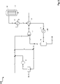
- a fresh gas stream 11 for example generated in a plant for autothermal reforming of natural gas (not shown), is combined with a hydrogen-containing stream 12, whereby a hydrogen-rich synthesis gas stream 13 with a stoichiometry number of 2.0 or greater is generated.
- the hydrogen-rich synthesis gas stream 13 is compressed by a compressor stage 30 to synthesis pressure.
- a portion of the hydrogen-rich synthesis gas stream 13 is separated off as a hydrogen-rich partial synthesis gas stream 14 and combined with a flushing gas stream 15 , resulting in a mixed synthesis gas stream 16 .
- the mixed synthesis gas stream 16 is fed to the hydrogen recovery stage 31, in which the hydrogen-containing stream 12 with a hydrogen content of at least 99% by volume is generated by alternating pressure absorption.
- Exhaust gas simultaneously generated in the hydrogen recovery stage 31 17, which contains carbon oxides and components that are inert under the conditions of methanol synthesis can be used, for example, as fuel gas in the reformer unit upstream of the methanol synthesis.
- the main part 18 of the hydrogen-rich synthesis gas stream compressed to synthesis pressure is combined with a residual gas stream 19 compressed to synthesis pressure in a compressor stage 32 .
- the resulting combined synthesis gas stream 20 is heated in a heat exchanger 33 and fed to a methanol reactor 34 as heated synthesis gas stream 21 .
- the methanol reactor 34 the conversion of the synthesis gas from synthesis gas stream 21 to methanol and water takes place on the methanol synthesis catalyst of the catalyst bed 35.
- the product stream 22 resulting from the reaction in reactor 34 which in addition to methanol and water also includes unreacted synthesis gas or residual gas, is then successively cooled via the heat exchangers 36, 33 and 37, with the product streams 23, 24 and 25 downstream of the respective heat exchangers result.
- the cooled product stream 25 is then separated in a separator 38 into a liquid phase comprising methanol and water and a gaseous phase comprising residual gas.
- the synthesis gas or residual gas that has not been converted in the reactor 34 is drawn off as residual gas stream 26 from the separator 38 .
- a crude methanol stream 27 comprising methanol and water is drawn off from the separator 38 and fed to further processing, for example a rectification (not shown).
- the flushing gas stream 15 is separated from the residual gas stream 26 and a remaining residual gas stream 28 is compressed in the compressor stage 32 to synthesis pressure. Residual gas stream 19 compressed to synthesis pressure is in turn combined with hydrogen-rich synthesis gas stream 18 and again fed to the conversion to methanol in the methanol reactor 34 .
- figure 2 shows a compared to the example of figure 1 modified type of process management according to a further example of the invention.
- the hydrogen-containing stream 12 generated in the hydrogen recovery stage 31 is compressed in a hydrogen compressor 40, wherein a compressed hydrogen-containing stream 51 is obtained, which is combined with the fresh gas stream 11.
- a hydrogen-rich synthesis gas stream 13 the main part 18 of which is fed to the compressor stage 41 for compression to synthesis pressure and part of which is branched off as a hydrogen-rich synthesis gas partial stream 14 and combined with the purge gas stream 15.
- the mixed synthesis gas stream 16 results from the streams 14 and 15 .
- the hydrogen-rich synthesis gas stream 18 and the residual gas stream are fed together to a compressor stage 41 .
- Compressor stage 41 has two nozzles on the suction side, which enables the simultaneous compression of the hydrogen-rich synthesis gas stream 18 and the residual gas stream 28, with the combined synthesis gas stream 20 being obtained, which is heated in the heat exchanger 33 and fed to the methanol reactor 34 as the synthesis gas stream 21.
- FIG 3 shows a type of process control known from the prior art.
- the hydrogen recovery stage 31 is also fed a mixed gas stream of synthesis gas and purge gas and used for hydrogen recovery.
- the synthesis gas portion of the mixed gas flow is a partial fresh gas flow 60 which is branched off from the (main) fresh gas flow 11 with the aid of the throttle element 70 .
- the partial make-up gas stream 60 and the purge gas stream 15 are combined and fed to the hydrogen recovery stage 31 as a mixed synthesis gas stream 61 .
- the mixed synthesis gas flow 61 is accordingly not generated from synthesis gas already enriched with hydrogen and flushing gas, but from fresh gas and flushing gas.
- this type of process procedure has disadvantages compared to the process according to the invention.
- a disadvantage results from the inevitable use of the throttling element 70 required for throttling the (main) fresh gas flow 11 .
- Example 1 is based on the procedure according to figure 1 , in comparison with the procedure according to the state of the art ( figure 3 - comparative example).
- the low-hydrogen synthesis gas stream or fresh gas stream (11) has the following composition according to Example 1 and Comparative Example: component Percentage (vol%) water 0.21 carbon dioxide 8.04 carbon monoxide 23:16 hydrogen 65.94 argon 0.12 nitrogen 0.52 methane 2.01
- Argon, nitrogen and methane are inert gas components under the conditions of methanol synthesis and are essentially removed from the synthesis circuit via the flushing gas stream (15).
- the hydrogen-rich synthesis gas stream (13, 18) has the following composition: component Percentage (vol%) water 0.19 carbon dioxide 7.54 carbon monoxide 21.71 hydrogen 68.07 argon 0.11 nitrogen 0.49 methane 1.89
- the amount of substance flow of hydrogen-rich synthesis gas fed to the hydrogen recovery stage (31) (share 14 in the total flow of the hydrogen-rich synthesis gas) is 1451.5 kmol/h.
- the mass flow of the flushing gas flow (15) is 1306.3 kmol/h.
- Both streams together form the mixed synthesis gas stream (16) with a molar flow rate of 2757.8 kmol/h. For Example 1, this results in a molar flow fraction or molar fraction of the hydrogen-rich synthesis gas flow in the mixed synthesis gas flow of 0.53.
- the amount of substance flow fraction or amount of substance fraction of the part (14) separated from the hydrogen-rich synthesis gas stream in relation to the total amount of substance flow of hydrogen-rich synthesis gas (13) is, according to example 1, 0.059.
- Example 2 is based on the procedure according to figure 2 , in comparison with the procedure according to the state of the art ( figure 3 - comparative example).
- the low-hydrogen synthesis gas stream or fresh gas stream (11) has the following composition according to Example 2 and Comparative Example: component Percentage (vol%) water 0.16 carbon dioxide 7.54 carbon monoxide 24.68 hydrogen 65.55 argon 0.12 nitrogen 0.09 methane 1.86
- the hydrogen-rich synthesis gas stream (13, 18) has the following composition: component Percentage (vol%) water 0.14 carbon dioxide 6.99 carbon monoxide 22.84 hydrogen 68:12 argon 0.11 nitrogen 0.08 methane 1.72
- the amount of substance flow of hydrogen-rich synthesis gas fed to the hydrogen recovery stage (31) (share 14 in the total flow of the hydrogen-rich synthesis gas) is 2280.0 kmol/hr.
- the mass flow of the flushing gas flow (15) is 976.4 kmol/hr.
- Both streams together form the mixed synthesis gas stream (16) with a molar flow rate of 3256.4 kmol/hr. For Example 2, this results in a molar flow fraction or molar fraction of the hydrogen-rich synthesis gas stream in the mixed synthesis gas stream of 0.70.
- the amount of substance flow fraction or amount of substance fraction of the part (14) separated from the hydrogen-rich synthesis gas stream in relation to the total amount of substance flow of hydrogen-rich synthesis gas (13) is, according to example 2, 0.091.
Claims (14)
- Procédé (100, 200) pour la production de méthanol, un courant contenant de l'hydrogène (12, 51) provenant d'une étape de récupération d'hydrogène (31) étant ajouté à un courant de gaz frais (11) provenant d'une unité de reformage, qui comprend de l'hydrogène et des oxydes de carbone, un courant de gaz de synthèse riche en hydrogène (13, 18) ayant un nombre stœchiométrique SN, défini par SN = [n(H2) - n(CO2)]/[n (CO) + n(CO2)], de 2,0 ou plus étant obtenu, et le courant de gaz de synthèse riche en hydrogène étant combiné à un courant de gaz résiduel (19, 28) et le courant de gaz de synthèse riche en hydrogène et le courant de gaz résiduel étant passés à pression élevée et température élevée à travers un lit d'un catalyseur de synthèse de méthanol (35), un courant de produit (22, 23, 24, 25) étant obtenu, qui comprend du méthanol et le courant de gaz résiduel, et le courant de produit étant refroidi pour séparer le méthanol (27) du courant de gaz résiduel,
caractérisé en ce que
une partie du courant de gaz résiduel est séparée en tant que courant de gaz de balayage (15) et une partie (14) du courant de gaz de synthèse riche en hydrogène est séparée et combinée avec le courant de gaz de balayage, un courant de gaz de synthèse mélangé (16) étant obtenu, et le courant de gaz de synthèse mélangé est amené à l'étape de récupération d'hydrogène pour produire le courant contenant de l'hydrogène. - Procédé selon la revendication 1, caractérisé en ce que le courant de gaz de synthèse riche en hydrogène est comprimé, et une partie du courant de gaz de synthèse riche en hydrogène comprimé (18) est séparée et combinée avec le courant de gaz de balayage.
- Procédé selon la revendication 2, caractérisé en ce que le courant de gaz résiduel est comprimé et combiné avec le courant de gaz de synthèse riche en hydrogène comprimé, et les courants combinés sont passés à travers le lit du catalyseur de synthèse de méthanol.
- Procédé selon la revendication 1, caractérisé en ce que le courant contenant de l'hydrogène est comprimé par un compresseur d'hydrogène (40), et le courant contenant de l'hydrogène comprimé est combiné avec le courant de gaz frais, le courant de gaz de synthèse riche en hydrogène étant obtenu, et une partie du courant de gaz de synthèse riche en hydrogène est séparée et combinée avec le courant de gaz de balayage.
- Procédé selon la revendication 4, caractérisé en ce que le courant de gaz de synthèse riche en hydrogène et le courant de gaz résiduel sont comprimés ensemble et passés à travers le lit du catalyseur de synthèse de méthanol.
- Procédé selon l'une quelconque des revendications précédentes, caractérisé en ce que la proportion de courant de matière du courant de gaz de synthèse riche en hydrogène par rapport au courant de gaz de synthèse mélangé est comprise entre 0,10 et 0,95, de préférence entre 0,20 et 0,90, de manière davantage préférée entre 0,30 et 0,80 et de manière davantage préférée entre 0,50 et 0,75.
- Procédé selon l'une quelconque des revendications précédentes, caractérisé en ce que la proportion de courant de matière de la partie séparée du courant de gaz de synthèse riche en hydrogène par rapport au courant de matière total de gaz de synthèse riche en hydrogène est comprise entre 0,001 et 0,999, de préférence entre 0,005 et 0,800, de manière davantage préférée entre 0,010 et 0,500, de manière davantage préférée entre 0,020 et 0,200 et de manière davantage préférée entre 0,050 et 0,100.
- Procédé selon l'une quelconque des revendications précédentes, caractérisé en ce que le courant de gaz de synthèse riche en hydrogène présente un nombre stœchiométrique SN de 2,00 à 2,20, de préférence de 2,02 à 2,10, et de manière davantage préférée de 2,05 à 2,07.
- Procédé selon l'une quelconque des revendications précédentes, caractérisé en ce que le courant de gaz frais présente un nombre stœchiométrique SN inférieur à 2,0, de préférence de 1,70 à 1,95, de manière davantage préférée de 1,75 à 1,90, et de manière davantage préférée de 1,78 à 1,85.
- Procédé selon l'une quelconque des revendications précédentes, caractérisé en ce que l'étape de récupération d'hydrogène comprend un dispositif d'absorption à pression alternée pour séparer l'hydrogène du courant de gaz de synthèse mélangé.
- Procédé selon l'une quelconque des revendications 1 à 9, caractérisé en ce que l'étape de récupération d'hydrogène comprend une étape de séparation à membrane pour séparer l'hydrogène du courant de gaz de synthèse mélangé.
- Procédé selon l'une quelconque des revendications précédentes, caractérisé en ce que le courant contenant de l'hydrogène présente une proportion d'hydrogène d'au moins 95 % en volume, de préférence d'au moins 99 % en volume, de manière davantage préférée d'au moins 99,5 % en volume, de manière davantage préférée d'au moins 99,9 % en volume.
- Installation (100, 200) pour la production de méthanol, présentant les composants d'installation suivants en liaison fluidique les uns avec les autres :une unité de reformage pour produire un courant de gaz frais (11) comprenant de l'hydrogène et des oxydes de carbone ;une étape de récupération d'hydrogène (31) pour produire un courant contenant de l'hydrogène (12, 51), l'unité de reformage et l'étape de récupération d'hydrogène étant configurées de telle sorte qu'à partir du courant contenant de l'hydrogène et du courant de gaz frais, un courant de gaz de synthèse riche en hydrogène (13) ayant un nombre stœchiométrique SN, défini par SN = [n(H2) - n(CO2)]/[n(CO) + n(CO2)], de 2,0 ou plus peut être obtenu ;une étape de réacteur (34) comprenant un lit de catalyseur de synthèse de méthanol (35), l'étape de réacteur étant configurée de telle sorte que le courant de gaz de synthèse riche en hydrogène et un courant de gaz résiduel (19, 26, 28) peuvent être passés à pression élevée et température élevées à travers le lit de catalyseur de synthèse de méthanol, ce qui permet d'obtenir un courant de produit (22, 23, 24, 25), qui comprend du méthanol et le courant de gaz résiduel ;un dispositif de refroidissement (33, 36, 37) pour refroidir le courant de produit, le dispositif de refroidissement étant configuré de telle sorte que le méthanol (27) peut être séparé du courant de gaz résiduel,caractérisée en ce quel'installation est configurée de telle sorte qu'une partie du courant de gaz résiduel peut être séparée en tant que courant de gaz de balayage et une partie du courant de gaz de synthèse peut être séparée et combinée avec le courant de gaz de balayage, ce qui permet d'obtenir un courant de gaz de synthèse mélangé (16), et le courant de gaz de synthèse mélangé peut être amené à l'étape de récupération d'hydrogène pour produire le courant contenant de l'hydrogène.
- Utilisation du procédé selon l'une quelconque des revendications 1 à 12 ou de l'installation selon la revendication 13 pour la production de méthanol à partir de gaz frais produit par reformage autotherme et/ou oxydation partielle.
Priority Applications (8)
| Application Number | Priority Date | Filing Date | Title |
|---|---|---|---|
| ES19020610T ES2926723T3 (es) | 2019-10-31 | 2019-10-31 | Procedimiento e instalación para la producción de metanol a partir de gas de síntesis rico en hidrógeno |
| EP19020610.2A EP3816145B1 (fr) | 2019-10-31 | 2019-10-31 | Procédé et système de fabrication de méthanol à partir de gaz de synthèse riche en hydrogène |
| PCT/EP2020/025472 WO2021083546A1 (fr) | 2019-10-31 | 2020-10-23 | Procédé et installation de production de méthanol à partir de gaz de synthèse riche en hydrogène |
| US17/773,306 US20220396539A1 (en) | 2019-10-31 | 2020-10-23 | Process and plant for producing methanol from hydrogen-rich synthesis gas |
| BR112022005830A BR112022005830A2 (pt) | 2019-10-31 | 2020-10-23 | Processo e usina para produzir metanol a partir de gás de síntese rico em hidrogênio |
| MX2022004681A MX2022004681A (es) | 2019-10-31 | 2020-10-23 | Proceso y planta para producir metanol a partir de gas de sintesis rico en hidrogeno. |
| CA3154753A CA3154753A1 (fr) | 2019-10-31 | 2020-10-23 | Procede et installation de production de methanol a partir de gaz de synthese riche en hydrogene |
| CN202080068224.XA CN114502525A (zh) | 2019-10-31 | 2020-10-23 | 用于从富含氢气的合成气生产甲醇的方法和设备 |
Applications Claiming Priority (1)
| Application Number | Priority Date | Filing Date | Title |
|---|---|---|---|
| EP19020610.2A EP3816145B1 (fr) | 2019-10-31 | 2019-10-31 | Procédé et système de fabrication de méthanol à partir de gaz de synthèse riche en hydrogène |
Publications (2)
| Publication Number | Publication Date |
|---|---|
| EP3816145A1 EP3816145A1 (fr) | 2021-05-05 |
| EP3816145B1 true EP3816145B1 (fr) | 2022-07-06 |
Family
ID=68426065
Family Applications (1)
| Application Number | Title | Priority Date | Filing Date |
|---|---|---|---|
| EP19020610.2A Active EP3816145B1 (fr) | 2019-10-31 | 2019-10-31 | Procédé et système de fabrication de méthanol à partir de gaz de synthèse riche en hydrogène |
Country Status (8)
| Country | Link |
|---|---|
| US (1) | US20220396539A1 (fr) |
| EP (1) | EP3816145B1 (fr) |
| CN (1) | CN114502525A (fr) |
| BR (1) | BR112022005830A2 (fr) |
| CA (1) | CA3154753A1 (fr) |
| ES (1) | ES2926723T3 (fr) |
| MX (1) | MX2022004681A (fr) |
| WO (1) | WO2021083546A1 (fr) |
Family Cites Families (4)
| Publication number | Priority date | Publication date | Assignee | Title |
|---|---|---|---|---|
| GB0510823D0 (en) | 2005-05-27 | 2005-07-06 | Johnson Matthey Plc | Methanol synthesis |
| DE102007040707B4 (de) * | 2007-08-29 | 2012-05-16 | Lurgi Gmbh | Verfahren und Anlage zur Herstellung von Methanol |
| DK3205622T3 (en) * | 2016-02-11 | 2018-08-06 | Ulrich Wagner | METHOD OF SYNTHESIS OF METHANOL |
| EP3219697B1 (fr) * | 2016-03-16 | 2018-06-13 | L'Air Liquide Société Anonyme pour l'Etude et l'Exploitation des Procédés Georges Claude | Synthese de methanol a partir de gaz de synthese ayant un manque d'hydrogene |
-
2019
- 2019-10-31 EP EP19020610.2A patent/EP3816145B1/fr active Active
- 2019-10-31 ES ES19020610T patent/ES2926723T3/es active Active
-
2020
- 2020-10-23 WO PCT/EP2020/025472 patent/WO2021083546A1/fr active Application Filing
- 2020-10-23 BR BR112022005830A patent/BR112022005830A2/pt unknown
- 2020-10-23 CA CA3154753A patent/CA3154753A1/fr active Pending
- 2020-10-23 MX MX2022004681A patent/MX2022004681A/es unknown
- 2020-10-23 US US17/773,306 patent/US20220396539A1/en active Pending
- 2020-10-23 CN CN202080068224.XA patent/CN114502525A/zh active Pending
Also Published As
| Publication number | Publication date |
|---|---|
| BR112022005830A2 (pt) | 2022-06-21 |
| EP3816145A1 (fr) | 2021-05-05 |
| WO2021083546A8 (fr) | 2022-03-24 |
| CA3154753A1 (fr) | 2021-05-06 |
| US20220396539A1 (en) | 2022-12-15 |
| ES2926723T3 (es) | 2022-10-27 |
| WO2021083546A1 (fr) | 2021-05-06 |
| MX2022004681A (es) | 2022-05-10 |
| CN114502525A (zh) | 2022-05-13 |
Similar Documents
| Publication | Publication Date | Title |
|---|---|---|
| EP3205622B1 (fr) | Procede de synthese de methanol | |
| EP3307675B1 (fr) | Procédé multipression pour la production d'ammoniac | |
| EP2281793B1 (fr) | Procédé et installation destinés à la fabrication de méthanol | |
| DE10057863C2 (de) | Mehrdruckverfahren zur Herstellung von Ammoniak | |
| DE102012112705A1 (de) | Verfahren zur Herstellung von Methanol aus Kohlendioxid | |
| WO2011101081A1 (fr) | Procédé de production de méthanol | |
| EP3954650A1 (fr) | Procédé et installation de fabrication d'hydrogène et de séparation du dioxyde de carbone | |
| EP3219697B1 (fr) | Synthese de methanol a partir de gaz de synthese ayant un manque d'hydrogene | |
| EP1814823B1 (fr) | Procede de production d'uree a partir de gaz naturel | |
| DE102017204208A1 (de) | Verfahren und Anlage zur Erzeugung und Aufbereitung eines Synthesegasgemisches | |
| EP2598618B1 (fr) | Procédé de production de gaz naturel de substitution | |
| EP3816145B1 (fr) | Procédé et système de fabrication de méthanol à partir de gaz de synthèse riche en hydrogène | |
| EP3782973B1 (fr) | Procédé et installation de fabrication de méthanol | |
| EP3782974B1 (fr) | Procédé et installation de fabrication de méthanol à partir de gaz de synthèse à teneur augmentée en dioxyde de carbone | |
| EP3741738B1 (fr) | Procédé de fabrication de méthanol | |
| EP3802410B1 (fr) | Procédé et dispositif de réalisation d'une conversion du gaz à l'eau | |
| EP3020696B1 (fr) | Procede de fabrication d'un ou plusieurs produits de reaction | |
| EP3969433A1 (fr) | Procédé et installation de synthèse de méthanol | |
| DE2904008C2 (fr) | ||
| EP3744416B1 (fr) | Procédé et installation de synthèse de méthanol | |
| EP3770140B1 (fr) | Procédé et installation de synthèse de méthanol | |
| WO2017207110A1 (fr) | Procédé et installation de fabrication d'éthanol | |
| EP4324815A1 (fr) | Procédé et installation de production de méthanol et de gaz de synthèse | |
| EP4066921A1 (fr) | Procédé et installation de production de méthanol et d'ammoniaque | |
| WO2017207107A1 (fr) | Procédé et installation de fabrication d'éthanol |
Legal Events
| Date | Code | Title | Description |
|---|---|---|---|
| PUAI | Public reference made under article 153(3) epc to a published international application that has entered the european phase |
Free format text: ORIGINAL CODE: 0009012 |
|
| STAA | Information on the status of an ep patent application or granted ep patent |
Free format text: STATUS: THE APPLICATION HAS BEEN PUBLISHED |
|
| AK | Designated contracting states |
Kind code of ref document: A1 Designated state(s): AL AT BE BG CH CY CZ DE DK EE ES FI FR GB GR HR HU IE IS IT LI LT LU LV MC MK MT NL NO PL PT RO RS SE SI SK SM TR |
|
| STAA | Information on the status of an ep patent application or granted ep patent |
Free format text: STATUS: REQUEST FOR EXAMINATION WAS MADE |
|
| 17P | Request for examination filed |
Effective date: 20211105 |
|
| RBV | Designated contracting states (corrected) |
Designated state(s): AL AT BE BG CH CY CZ DE DK EE ES FI FR GB GR HR HU IE IS IT LI LT LU LV MC MK MT NL NO PL PT RO RS SE SI SK SM TR |
|
| GRAP | Despatch of communication of intention to grant a patent |
Free format text: ORIGINAL CODE: EPIDOSNIGR1 |
|
| STAA | Information on the status of an ep patent application or granted ep patent |
Free format text: STATUS: GRANT OF PATENT IS INTENDED |
|
| RIC1 | Information provided on ipc code assigned before grant |
Ipc: C01B 3/38 20060101ALI20220303BHEP Ipc: C07C 31/04 20060101ALI20220303BHEP Ipc: C07C 29/151 20060101AFI20220303BHEP |
|
| INTG | Intention to grant announced |
Effective date: 20220321 |
|
| GRAS | Grant fee paid |
Free format text: ORIGINAL CODE: EPIDOSNIGR3 |
|
| GRAA | (expected) grant |
Free format text: ORIGINAL CODE: 0009210 |
|
| STAA | Information on the status of an ep patent application or granted ep patent |
Free format text: STATUS: THE PATENT HAS BEEN GRANTED |
|
| AK | Designated contracting states |
Kind code of ref document: B1 Designated state(s): AL AT BE BG CH CY CZ DE DK EE ES FI FR GB GR HR HU IE IS IT LI LT LU LV MC MK MT NL NO PL PT RO RS SE SI SK SM TR |
|
| REG | Reference to a national code |
Ref country code: AT Ref legal event code: REF Ref document number: 1502787 Country of ref document: AT Kind code of ref document: T Effective date: 20220715 Ref country code: CH Ref legal event code: EP |
|
| REG | Reference to a national code |
Ref country code: DE Ref legal event code: R096 Ref document number: 502019004844 Country of ref document: DE |
|
| REG | Reference to a national code |
Ref country code: IE Ref legal event code: FG4D Free format text: LANGUAGE OF EP DOCUMENT: GERMAN |
|
| REG | Reference to a national code |
Ref country code: NL Ref legal event code: FP |
|
| REG | Reference to a national code |
Ref country code: LT Ref legal event code: MG9D |
|
| REG | Reference to a national code |
Ref country code: ES Ref legal event code: FG2A Ref document number: 2926723 Country of ref document: ES Kind code of ref document: T3 Effective date: 20221027 |
|
| PG25 | Lapsed in a contracting state [announced via postgrant information from national office to epo] |
Ref country code: SE Free format text: LAPSE BECAUSE OF FAILURE TO SUBMIT A TRANSLATION OF THE DESCRIPTION OR TO PAY THE FEE WITHIN THE PRESCRIBED TIME-LIMIT Effective date: 20220706 Ref country code: RS Free format text: LAPSE BECAUSE OF FAILURE TO SUBMIT A TRANSLATION OF THE DESCRIPTION OR TO PAY THE FEE WITHIN THE PRESCRIBED TIME-LIMIT Effective date: 20220706 Ref country code: PT Free format text: LAPSE BECAUSE OF FAILURE TO SUBMIT A TRANSLATION OF THE DESCRIPTION OR TO PAY THE FEE WITHIN THE PRESCRIBED TIME-LIMIT Effective date: 20221107 Ref country code: NO Free format text: LAPSE BECAUSE OF FAILURE TO SUBMIT A TRANSLATION OF THE DESCRIPTION OR TO PAY THE FEE WITHIN THE PRESCRIBED TIME-LIMIT Effective date: 20221006 Ref country code: LV Free format text: LAPSE BECAUSE OF FAILURE TO SUBMIT A TRANSLATION OF THE DESCRIPTION OR TO PAY THE FEE WITHIN THE PRESCRIBED TIME-LIMIT Effective date: 20220706 Ref country code: LT Free format text: LAPSE BECAUSE OF FAILURE TO SUBMIT A TRANSLATION OF THE DESCRIPTION OR TO PAY THE FEE WITHIN THE PRESCRIBED TIME-LIMIT Effective date: 20220706 Ref country code: FI Free format text: LAPSE BECAUSE OF FAILURE TO SUBMIT A TRANSLATION OF THE DESCRIPTION OR TO PAY THE FEE WITHIN THE PRESCRIBED TIME-LIMIT Effective date: 20220706 |
|
| PG25 | Lapsed in a contracting state [announced via postgrant information from national office to epo] |
Ref country code: PL Free format text: LAPSE BECAUSE OF FAILURE TO SUBMIT A TRANSLATION OF THE DESCRIPTION OR TO PAY THE FEE WITHIN THE PRESCRIBED TIME-LIMIT Effective date: 20220706 Ref country code: IS Free format text: LAPSE BECAUSE OF FAILURE TO SUBMIT A TRANSLATION OF THE DESCRIPTION OR TO PAY THE FEE WITHIN THE PRESCRIBED TIME-LIMIT Effective date: 20221106 Ref country code: GR Free format text: LAPSE BECAUSE OF FAILURE TO SUBMIT A TRANSLATION OF THE DESCRIPTION OR TO PAY THE FEE WITHIN THE PRESCRIBED TIME-LIMIT Effective date: 20221007 |
|
| PGFP | Annual fee paid to national office [announced via postgrant information from national office to epo] |
Ref country code: BE Payment date: 20221019 Year of fee payment: 4 |
|
| REG | Reference to a national code |
Ref country code: DE Ref legal event code: R097 Ref document number: 502019004844 Country of ref document: DE |
|
| PG25 | Lapsed in a contracting state [announced via postgrant information from national office to epo] |
Ref country code: SM Free format text: LAPSE BECAUSE OF FAILURE TO SUBMIT A TRANSLATION OF THE DESCRIPTION OR TO PAY THE FEE WITHIN THE PRESCRIBED TIME-LIMIT Effective date: 20220706 Ref country code: RO Free format text: LAPSE BECAUSE OF FAILURE TO SUBMIT A TRANSLATION OF THE DESCRIPTION OR TO PAY THE FEE WITHIN THE PRESCRIBED TIME-LIMIT Effective date: 20220706 Ref country code: DK Free format text: LAPSE BECAUSE OF FAILURE TO SUBMIT A TRANSLATION OF THE DESCRIPTION OR TO PAY THE FEE WITHIN THE PRESCRIBED TIME-LIMIT Effective date: 20220706 Ref country code: CZ Free format text: LAPSE BECAUSE OF FAILURE TO SUBMIT A TRANSLATION OF THE DESCRIPTION OR TO PAY THE FEE WITHIN THE PRESCRIBED TIME-LIMIT Effective date: 20220706 |
|
| PLBE | No opposition filed within time limit |
Free format text: ORIGINAL CODE: 0009261 |
|
| STAA | Information on the status of an ep patent application or granted ep patent |
Free format text: STATUS: NO OPPOSITION FILED WITHIN TIME LIMIT |
|
| PG25 | Lapsed in a contracting state [announced via postgrant information from national office to epo] |
Ref country code: SK Free format text: LAPSE BECAUSE OF FAILURE TO SUBMIT A TRANSLATION OF THE DESCRIPTION OR TO PAY THE FEE WITHIN THE PRESCRIBED TIME-LIMIT Effective date: 20220706 Ref country code: MC Free format text: LAPSE BECAUSE OF FAILURE TO SUBMIT A TRANSLATION OF THE DESCRIPTION OR TO PAY THE FEE WITHIN THE PRESCRIBED TIME-LIMIT Effective date: 20220706 Ref country code: EE Free format text: LAPSE BECAUSE OF FAILURE TO SUBMIT A TRANSLATION OF THE DESCRIPTION OR TO PAY THE FEE WITHIN THE PRESCRIBED TIME-LIMIT Effective date: 20220706 |
|
| REG | Reference to a national code |
Ref country code: CH Ref legal event code: PL |
|
| 26N | No opposition filed |
Effective date: 20230411 |
|
| P01 | Opt-out of the competence of the unified patent court (upc) registered |
Effective date: 20230518 |
|
| PG25 | Lapsed in a contracting state [announced via postgrant information from national office to epo] |
Ref country code: LU Free format text: LAPSE BECAUSE OF NON-PAYMENT OF DUE FEES Effective date: 20221031 Ref country code: AL Free format text: LAPSE BECAUSE OF FAILURE TO SUBMIT A TRANSLATION OF THE DESCRIPTION OR TO PAY THE FEE WITHIN THE PRESCRIBED TIME-LIMIT Effective date: 20220706 |
|
| PG25 | Lapsed in a contracting state [announced via postgrant information from national office to epo] |
Ref country code: LI Free format text: LAPSE BECAUSE OF NON-PAYMENT OF DUE FEES Effective date: 20221031 Ref country code: CH Free format text: LAPSE BECAUSE OF NON-PAYMENT OF DUE FEES Effective date: 20221031 |
|
| PG25 | Lapsed in a contracting state [announced via postgrant information from national office to epo] |
Ref country code: SI Free format text: LAPSE BECAUSE OF FAILURE TO SUBMIT A TRANSLATION OF THE DESCRIPTION OR TO PAY THE FEE WITHIN THE PRESCRIBED TIME-LIMIT Effective date: 20220706 |
|
| PG25 | Lapsed in a contracting state [announced via postgrant information from national office to epo] |
Ref country code: IE Free format text: LAPSE BECAUSE OF NON-PAYMENT OF DUE FEES Effective date: 20221031 |
|
| PGFP | Annual fee paid to national office [announced via postgrant information from national office to epo] |
Ref country code: NL Payment date: 20231019 Year of fee payment: 5 |
|
| PGFP | Annual fee paid to national office [announced via postgrant information from national office to epo] |
Ref country code: GB Payment date: 20231020 Year of fee payment: 5 |
|
| PGFP | Annual fee paid to national office [announced via postgrant information from national office to epo] |
Ref country code: ES Payment date: 20231227 Year of fee payment: 5 |
|
| PGFP | Annual fee paid to national office [announced via postgrant information from national office to epo] |
Ref country code: IT Payment date: 20231023 Year of fee payment: 5 Ref country code: FR Payment date: 20231026 Year of fee payment: 5 Ref country code: DE Payment date: 20231020 Year of fee payment: 5 |
|
| PGFP | Annual fee paid to national office [announced via postgrant information from national office to epo] |
Ref country code: BE Payment date: 20231019 Year of fee payment: 5 |