EP3816145B1 - Method and installation for producing methanol from hydrogen-rich synthesis gas - Google Patents
Method and installation for producing methanol from hydrogen-rich synthesis gas Download PDFInfo
- Publication number
- EP3816145B1 EP3816145B1 EP19020610.2A EP19020610A EP3816145B1 EP 3816145 B1 EP3816145 B1 EP 3816145B1 EP 19020610 A EP19020610 A EP 19020610A EP 3816145 B1 EP3816145 B1 EP 3816145B1
- Authority
- EP
- European Patent Office
- Prior art keywords
- hydrogen
- gas stream
- synthesis gas
- stream
- methanol
- Prior art date
- Legal status (The legal status is an assumption and is not a legal conclusion. Google has not performed a legal analysis and makes no representation as to the accuracy of the status listed.)
- Active
Links
- 239000007789 gas Substances 0.000 title claims description 273
- OKKJLVBELUTLKV-UHFFFAOYSA-N Methanol Chemical compound OC OKKJLVBELUTLKV-UHFFFAOYSA-N 0.000 title claims description 240
- 238000003786 synthesis reaction Methods 0.000 title claims description 195
- 230000015572 biosynthetic process Effects 0.000 title claims description 194
- 229910052739 hydrogen Inorganic materials 0.000 title claims description 183
- 239000001257 hydrogen Substances 0.000 title claims description 183
- UFHFLCQGNIYNRP-UHFFFAOYSA-N Hydrogen Chemical compound [H][H] UFHFLCQGNIYNRP-UHFFFAOYSA-N 0.000 title claims description 172
- 238000000034 method Methods 0.000 title claims description 49
- 238000009434 installation Methods 0.000 title 1
- 238000011084 recovery Methods 0.000 claims description 36
- 239000003054 catalyst Substances 0.000 claims description 30
- UGFAIRIUMAVXCW-UHFFFAOYSA-N Carbon monoxide Chemical class [O+]#[C-] UGFAIRIUMAVXCW-UHFFFAOYSA-N 0.000 claims description 26
- 238000010926 purge Methods 0.000 claims description 20
- 229910002090 carbon oxide Inorganic materials 0.000 claims description 11
- 150000002431 hydrogen Chemical class 0.000 claims description 7
- 238000010521 absorption reaction Methods 0.000 claims description 6
- 238000002453 autothermal reforming Methods 0.000 claims description 6
- 230000003647 oxidation Effects 0.000 claims description 5
- 238000007254 oxidation reaction Methods 0.000 claims description 5
- 238000001816 cooling Methods 0.000 claims description 4
- 239000012528 membrane Substances 0.000 claims description 3
- 238000000926 separation method Methods 0.000 claims description 3
- 239000012530 fluid Substances 0.000 claims description 2
- VNWKTOKETHGBQD-UHFFFAOYSA-N methane Chemical compound C VNWKTOKETHGBQD-UHFFFAOYSA-N 0.000 description 20
- 229910002091 carbon monoxide Inorganic materials 0.000 description 17
- 238000004519 manufacturing process Methods 0.000 description 17
- XLYOFNOQVPJJNP-UHFFFAOYSA-N water Substances O XLYOFNOQVPJJNP-UHFFFAOYSA-N 0.000 description 15
- 238000011010 flushing procedure Methods 0.000 description 13
- 239000000203 mixture Substances 0.000 description 13
- CURLTUGMZLYLDI-UHFFFAOYSA-N Carbon dioxide Chemical compound O=C=O CURLTUGMZLYLDI-UHFFFAOYSA-N 0.000 description 12
- 241000196324 Embryophyta Species 0.000 description 12
- 238000006243 chemical reaction Methods 0.000 description 11
- 230000000052 comparative effect Effects 0.000 description 11
- XKRFYHLGVUSROY-UHFFFAOYSA-N Argon Chemical compound [Ar] XKRFYHLGVUSROY-UHFFFAOYSA-N 0.000 description 10
- IJGRMHOSHXDMSA-UHFFFAOYSA-N Atomic nitrogen Chemical compound N#N IJGRMHOSHXDMSA-UHFFFAOYSA-N 0.000 description 10
- 230000006835 compression Effects 0.000 description 9
- 238000007906 compression Methods 0.000 description 9
- 239000000047 product Substances 0.000 description 8
- 239000000126 substance Substances 0.000 description 8
- 229910002092 carbon dioxide Inorganic materials 0.000 description 6
- 239000001569 carbon dioxide Substances 0.000 description 6
- 229910052786 argon Inorganic materials 0.000 description 5
- 239000003345 natural gas Substances 0.000 description 5
- 229910052757 nitrogen Inorganic materials 0.000 description 5
- RYGMFSIKBFXOCR-UHFFFAOYSA-N Copper Chemical compound [Cu] RYGMFSIKBFXOCR-UHFFFAOYSA-N 0.000 description 4
- 229910052802 copper Inorganic materials 0.000 description 4
- 239000010949 copper Substances 0.000 description 4
- 239000003245 coal Substances 0.000 description 3
- 230000006735 deficit Effects 0.000 description 3
- 238000010586 diagram Methods 0.000 description 3
- 238000011835 investigation Methods 0.000 description 3
- 238000004886 process control Methods 0.000 description 3
- XLOMVQKBTHCTTD-UHFFFAOYSA-N Zinc monoxide Chemical compound [Zn]=O XLOMVQKBTHCTTD-UHFFFAOYSA-N 0.000 description 2
- 239000006227 byproduct Substances 0.000 description 2
- 230000002950 deficient Effects 0.000 description 2
- 238000005265 energy consumption Methods 0.000 description 2
- 238000002309 gasification Methods 0.000 description 2
- 239000007787 solid Substances 0.000 description 2
- 239000002028 Biomass Substances 0.000 description 1
- OKTJSMMVPCPJKN-UHFFFAOYSA-N Carbon Chemical compound [C] OKTJSMMVPCPJKN-UHFFFAOYSA-N 0.000 description 1
- 241000183024 Populus tremula Species 0.000 description 1
- 150000001298 alcohols Chemical class 0.000 description 1
- 238000009835 boiling Methods 0.000 description 1
- 229910052799 carbon Inorganic materials 0.000 description 1
- 238000004891 communication Methods 0.000 description 1
- 238000009833 condensation Methods 0.000 description 1
- 230000005494 condensation Effects 0.000 description 1
- 230000001419 dependent effect Effects 0.000 description 1
- 230000005611 electricity Effects 0.000 description 1
- 239000002737 fuel gas Substances 0.000 description 1
- 239000007792 gaseous phase Substances 0.000 description 1
- 239000011261 inert gas Substances 0.000 description 1
- 239000004615 ingredient Substances 0.000 description 1
- 150000002576 ketones Chemical class 0.000 description 1
- 239000007791 liquid phase Substances 0.000 description 1
- 239000000463 material Substances 0.000 description 1
- 239000010813 municipal solid waste Substances 0.000 description 1
- 210000000056 organ Anatomy 0.000 description 1
- TWNQGVIAIRXVLR-UHFFFAOYSA-N oxo(oxoalumanyloxy)alumane Chemical compound O=[Al]O[Al]=O TWNQGVIAIRXVLR-UHFFFAOYSA-N 0.000 description 1
- 239000011541 reaction mixture Substances 0.000 description 1
- 238000002407 reforming Methods 0.000 description 1
- 239000002910 solid waste Substances 0.000 description 1
- 238000011064 split stream procedure Methods 0.000 description 1
- 238000011144 upstream manufacturing Methods 0.000 description 1
- 239000002912 waste gas Substances 0.000 description 1
- 239000011787 zinc oxide Substances 0.000 description 1
Images


Classifications
-
- C—CHEMISTRY; METALLURGY
- C07—ORGANIC CHEMISTRY
- C07C—ACYCLIC OR CARBOCYCLIC COMPOUNDS
- C07C29/00—Preparation of compounds having hydroxy or O-metal groups bound to a carbon atom not belonging to a six-membered aromatic ring
- C07C29/15—Preparation of compounds having hydroxy or O-metal groups bound to a carbon atom not belonging to a six-membered aromatic ring by reduction of oxides of carbon exclusively
- C07C29/151—Preparation of compounds having hydroxy or O-metal groups bound to a carbon atom not belonging to a six-membered aromatic ring by reduction of oxides of carbon exclusively with hydrogen or hydrogen-containing gases
- C07C29/1516—Multisteps
- C07C29/1518—Multisteps one step being the formation of initial mixture of carbon oxides and hydrogen for synthesis
-
- B—PERFORMING OPERATIONS; TRANSPORTING
- B01—PHYSICAL OR CHEMICAL PROCESSES OR APPARATUS IN GENERAL
- B01J—CHEMICAL OR PHYSICAL PROCESSES, e.g. CATALYSIS OR COLLOID CHEMISTRY; THEIR RELEVANT APPARATUS
- B01J3/00—Processes of utilising sub-atmospheric or super-atmospheric pressure to effect chemical or physical change of matter; Apparatus therefor
- B01J3/04—Pressure vessels, e.g. autoclaves
-
- C—CHEMISTRY; METALLURGY
- C01—INORGANIC CHEMISTRY
- C01B—NON-METALLIC ELEMENTS; COMPOUNDS THEREOF; METALLOIDS OR COMPOUNDS THEREOF NOT COVERED BY SUBCLASS C01C
- C01B3/00—Hydrogen; Gaseous mixtures containing hydrogen; Separation of hydrogen from mixtures containing it; Purification of hydrogen
- C01B3/02—Production of hydrogen or of gaseous mixtures containing a substantial proportion of hydrogen
- C01B3/32—Production of hydrogen or of gaseous mixtures containing a substantial proportion of hydrogen by reaction of gaseous or liquid organic compounds with gasifying agents, e.g. water, carbon dioxide, air
- C01B3/34—Production of hydrogen or of gaseous mixtures containing a substantial proportion of hydrogen by reaction of gaseous or liquid organic compounds with gasifying agents, e.g. water, carbon dioxide, air by reaction of hydrocarbons with gasifying agents
- C01B3/38—Production of hydrogen or of gaseous mixtures containing a substantial proportion of hydrogen by reaction of gaseous or liquid organic compounds with gasifying agents, e.g. water, carbon dioxide, air by reaction of hydrocarbons with gasifying agents using catalysts
- C01B3/382—Multi-step processes
-
- C—CHEMISTRY; METALLURGY
- C07—ORGANIC CHEMISTRY
- C07C—ACYCLIC OR CARBOCYCLIC COMPOUNDS
- C07C29/00—Preparation of compounds having hydroxy or O-metal groups bound to a carbon atom not belonging to a six-membered aromatic ring
- C07C29/15—Preparation of compounds having hydroxy or O-metal groups bound to a carbon atom not belonging to a six-membered aromatic ring by reduction of oxides of carbon exclusively
- C07C29/151—Preparation of compounds having hydroxy or O-metal groups bound to a carbon atom not belonging to a six-membered aromatic ring by reduction of oxides of carbon exclusively with hydrogen or hydrogen-containing gases
- C07C29/152—Preparation of compounds having hydroxy or O-metal groups bound to a carbon atom not belonging to a six-membered aromatic ring by reduction of oxides of carbon exclusively with hydrogen or hydrogen-containing gases characterised by the reactor used
-
- C—CHEMISTRY; METALLURGY
- C01—INORGANIC CHEMISTRY
- C01B—NON-METALLIC ELEMENTS; COMPOUNDS THEREOF; METALLOIDS OR COMPOUNDS THEREOF NOT COVERED BY SUBCLASS C01C
- C01B2203/00—Integrated processes for the production of hydrogen or synthesis gas
- C01B2203/02—Processes for making hydrogen or synthesis gas
- C01B2203/0205—Processes for making hydrogen or synthesis gas containing a reforming step
- C01B2203/0227—Processes for making hydrogen or synthesis gas containing a reforming step containing a catalytic reforming step
- C01B2203/0244—Processes for making hydrogen or synthesis gas containing a reforming step containing a catalytic reforming step the reforming step being an autothermal reforming step, e.g. secondary reforming processes
-
- C—CHEMISTRY; METALLURGY
- C01—INORGANIC CHEMISTRY
- C01B—NON-METALLIC ELEMENTS; COMPOUNDS THEREOF; METALLOIDS OR COMPOUNDS THEREOF NOT COVERED BY SUBCLASS C01C
- C01B2203/00—Integrated processes for the production of hydrogen or synthesis gas
- C01B2203/04—Integrated processes for the production of hydrogen or synthesis gas containing a purification step for the hydrogen or the synthesis gas
- C01B2203/042—Purification by adsorption on solids
- C01B2203/043—Regenerative adsorption process in two or more beds, one for adsorption, the other for regeneration
-
- C—CHEMISTRY; METALLURGY
- C01—INORGANIC CHEMISTRY
- C01B—NON-METALLIC ELEMENTS; COMPOUNDS THEREOF; METALLOIDS OR COMPOUNDS THEREOF NOT COVERED BY SUBCLASS C01C
- C01B2203/00—Integrated processes for the production of hydrogen or synthesis gas
- C01B2203/06—Integration with other chemical processes
- C01B2203/061—Methanol production
-
- Y—GENERAL TAGGING OF NEW TECHNOLOGICAL DEVELOPMENTS; GENERAL TAGGING OF CROSS-SECTIONAL TECHNOLOGIES SPANNING OVER SEVERAL SECTIONS OF THE IPC; TECHNICAL SUBJECTS COVERED BY FORMER USPC CROSS-REFERENCE ART COLLECTIONS [XRACs] AND DIGESTS
- Y02—TECHNOLOGIES OR APPLICATIONS FOR MITIGATION OR ADAPTATION AGAINST CLIMATE CHANGE
- Y02P—CLIMATE CHANGE MITIGATION TECHNOLOGIES IN THE PRODUCTION OR PROCESSING OF GOODS
- Y02P20/00—Technologies relating to chemical industry
- Y02P20/50—Improvements relating to the production of bulk chemicals
- Y02P20/52—Improvements relating to the production of bulk chemicals using catalysts, e.g. selective catalysts
Definitions
- the invention relates to a method and a plant for producing methanol from a hydrogen-poor fresh gas stream, a hydrogen-containing stream being fed to the hydrogen-poor fresh gas stream so that a hydrogen-rich synthesis gas stream with a stoichiometry number of 2.0 or greater is obtained.
- the invention also relates to the use of the method according to the invention or the plant according to the invention for the production of methanol from fresh gas produced by autothermal reforming and/or partial oxidation.
- Synthesis gas is a mixture of mainly hydrogen (H 2 ), carbon monoxide (CO) and carbon dioxide (CO 2 ). In addition, it contains small amounts of gas components that are inert under the conditions of methanol synthesis. Carbon monoxide and carbon dioxide are often combined under the term "carbon oxides" or "carbon oxides".
- the synthesis gas is converted into methanol and water (as an inevitable by-product) at a synthesis pressure of 60 to 120 bar.
- That Synthesis gas used is passed through a catalyst bed of a methanol synthesis catalyst after compression to the respective synthesis pressure at catalyst temperatures of usually greater than 200 °C.
- the methanol synthesis catalyst is usually a composition having copper as the catalytically active species.
- one or more reactors connected in series or in parallel are used, each of which has a corresponding catalyst bed.
- the conversion of the carbon oxides into methanol and water on the catalyst is due to the establishment of a thermodynamic equilibrium in accordance with the reactions not completely. For this reason, the manufacturing process is usually run as a circulatory process in a so-called synthesis loop.
- reaction mixture obtained at the reactor outlet is cooled below the boiling point of methanol in order to separate methanol and water from the circuit.
- unreacted synthesis gas is returned to the methanol synthesis catalyst for renewed reaction.
- a partial flow of the unreacted synthesis gas is continuously removed as a purge gas flow in order to avoid an increase in the concentration of inert components in the synthesis loop over time.
- a fresh gas composition that is stoichiometrically balanced for the methanol synthesis is characterized by a stoichiometric number SN of 2.0.
- Values less than 2.0 indicate a hydrogen deficit, while values greater than 2.0 indicate a hydrogen excess.
- Hydrogen-deficient synthesis gases are obtained, for example, from processes which include a partial oxidation step or from the production of synthesis gas by coal gasification. In such a case, the hydrogen is almost completely consumed in the methanol synthesis, while a substantial part of the carbon oxides is not converted. This leads to a composition in the synthesis loop characterized by a high proportion of carbon oxides but a low proportion of hydrogen.
- the methanol synthesis reactor has to be designed with a high catalyst volume and that the content of by-products (in particular higher alcohols and ketones) is higher than desired.
- the synthesis gas can be adjusted to the desired stoichiometry number of two or greater, for example by means of hydrogen from a hydrogen recovery plant. This is possible, for example, by recovering hydrogen from the purge flow.
- EP 3 205 622 B1 discloses a process in which unreacted synthesis gas, referred to as tail gas, is partially fed (as purge gas) to a hydrogen recovery stage. A hydrogen-containing stream is obtained, which is fed to the fresh gas stream. The resulting mixture is then compressed to synthesis pressure and converted to methanol.
- the amounts of hydrogen to be obtained from the substream of the unreacted synthesis gas are often not sufficient to obtain a synthesis gas with a sufficiently high stoichiometry number.
- synthesis gases with a high hydrogen deficit may require such a high proportion of hydrogen recovery purge flow that the synthesis loop must either be operated at low pressures or that the ratio of recycle gas flow to make-up gas flow must be set low.
- U.S. 7,786,180 B2 therefore proposes feeding a mixed flow of make-up gas and purge gas to the hydrogen recovery stage in order to at least partially overcome the above disadvantages.
- a disadvantage of this arrangement is, for example, that the fresh gas flow has to be throttled by a pressure-reducing valve in order to at least compensate for the pressure loss generated by the hydrogen recovery stage. The pressure lost in the fresh gas line as a result must be compensated for in the subsequent compression to synthesis pressure.
- One object of the present invention is to provide a method and a plant for the production of methanol, which at least partially overcomes the disadvantages of the prior art.
- part of the residual gas stream is separated off as a flushing gas stream and part of the hydrogen-rich synthesis gas stream is separated off and combined with the flushing gas stream, a mixed synthesis gas stream being obtained, and the mixed synthesis gas stream being fed to the hydrogen recovery stage to generate the hydrogen-containing stream.
- the fresh gas stream and the purge gas stream branched off from the residual gas stream are not fed to the hydrogen recovery stage, but rather the hydrogen-rich synthesis gas stream, which has already been adjusted with hydrogen to a stoichiometry number of 2.0 or greater, is fed to the hydrogen recovery stage together with the purge gas stream.
- the hydrogen-rich synthesis gas stream which has already been adjusted with hydrogen to a stoichiometry number of 2.0 or greater.
- the fresh gas flow is preferably a synthesis gas flow from a reformer unit, which is characterized in particular by a hydrogen deficit, so that the stoichiometry number of the fresh gas is in particular less than 2.0.
- a fresh gas stream is generated in particular in a reformer unit, which includes a partial oxidation step of a carbon-containing feed gas to generate the synthesis gas.
- the fresh gas stream can be generated from autothermal reforming of a carbonaceous feed gas.
- the feed gas is preferably natural gas.
- the fresh gas stream can be generated from coal gasification.
- the fresh gas stream Before the hydrogen-containing stream is fed in and compressed to synthesis pressure, the fresh gas stream is cooled to a temperature of preferably 40° C. or less for condensation and removal of water.
- the fresh gas stream usually has a pressure of between 35 and 60 bar, which is why additional compression to synthesis pressure is required before the reaction on the methanol synthesis catalyst.
- a reformer unit may comprise a unit for converting (reforming) a gaseous carbonaceous feedstock or a solid carbonaceous feedstock.
- a gaseous carbonaceous feedstock is natural gas.
- solid carbonaceous feedstocks are coal, solid waste (garbage) and biomass.
- the hydrogen-containing stream preferably has a hydrogen content of 95% by volume or more.
- the aim is a hydrogen-containing stream which contains pure or essentially pure hydrogen.
- the hydrogen recovery stage also produces a waste gas stream which comprises components which are inert under the conditions of the methanol synthesis and also small amounts of unreacted carbon oxides.
- the conversion of the hydrogen-rich synthesis gas stream and the residual gas stream to methanol (and water) takes place at the methanol synthesis catalyst.
- the reaction takes place in a synthesis loop, ie what is not reacted on the catalyst Synthesis gas is fed back (recycled) as a residual gas stream to the inlet of the relevant reactor and converted to methanol on the methanol synthesis catalyst together with the hydrogen-rich synthesis gas used for the first time.
- the reaction over the methanol synthesis catalyst preferably takes place at a catalyst temperature of from 220° C. to 270° C. and preferably at a pressure of from 55 bar to 80 bar.
- the reaction over the methanol synthesis catalyst preferably takes place in one or more reactor stages connected in series or in parallel, each of the reactor stages comprising a corresponding catalyst bed.
- the reactor stages comprise a water-cooled reactor and a gas-cooled reactor downstream of the water-cooled reactor.
- Suitable catalysts are copper-based materials known from the prior art with copper as the catalytically active species, an example of this is a catalyst composition which comprises copper, zinc oxide and aluminum oxide.
- a preferred embodiment of the method according to the invention is characterized in that the hydrogen-rich synthesis gas stream is compressed and a portion of the compressed hydrogen-rich synthesis gas stream is separated and combined with the flushing gas stream.
- the hydrogen-rich synthesis gas stream is preferably compressed to synthesis pressure.
- the hydrogen-rich synthesis gas stream is compressed to a pressure of 70 bar or more and up to a pressure of 90 bar.
- savings in the required compression energy are achieved by this type of process control.
- the tail gas stream is compressed and combined with the compressed hydrogen-rich synthesis gas stream and the combined streams are passed through the methanol synthesis catalyst bed.
- the flushing gas flow is branched off from the residual gas flow, in particular before the residual gas flow is compressed.
- the residual gas stream is preferably compressed to synthesis pressure.
- the residual gas stream is preferably compressed to a pressure of 70 bar or more and up to a pressure of 90 bar.
- a preferred embodiment of the method according to the invention is characterized in that the hydrogen-containing stream is compressed by a hydrogen compressor, and the compressed hydrogen-containing stream is combined with the fresh gas stream, the hydrogen-rich synthesis gas stream being obtained, and a portion of the hydrogen-rich synthesis gas stream is separated and combined with the purge gas stream is merged.
- the hydrogen-containing stream is compressed by the hydrogen compressor to a pressure which is approximately 1 to 2 bar above the pressure of the fresh gas (approx. 35 to 60 bar).
- the hydrogen-rich synthesis gas stream and the residual gas stream are preferably compressed together and passed through the bed of the methanol synthesis catalyst.
- the hydrogen-rich synthesis gas stream and the residual gas stream are preferably compressed together to synthesis pressure.
- the hydrogen-rich synthesis gas stream and the residual gas stream are compressed together to a pressure of 70 bar or more and up to a pressure of 90 bar.
- the flushing gas stream is inevitably branched off from the residual gas stream before the common compression of the residual gas stream and the hydrogen-rich synthesis gas stream.
- a preferred embodiment of the method according to the invention is characterized in that the mass flow fraction of the hydrogen-rich synthesis gas flow in the mixed synthesis gas flow is between 0.10 and 0.95, preferably between 0.20 and 0.90, more preferably between 0.30 and 0 .80 and more preferably between 0.50 and 0.75.
- the mass flow rate can be represented, for example, by the unit “kmol/h” (kilomoles per hour).
- a preferred embodiment of the method according to the invention is characterized in that the mass flow fraction of the part separated from the hydrogen-rich synthesis gas flow in relation to the total mass flow of hydrogen-rich synthesis gas is between 0.001 and 0.999, preferably between 0.005 and 0.800, more preferably between 0.010 and 0.500, more preferably between 0.020 and 0.200 and more preferably between 0.050 and 0.100.
- a preferred embodiment of the method according to the invention is characterized in that the hydrogen-rich synthesis gas stream has a stoichiometry number SN from 2.00 to 2.20, preferably from 2.02 to 2.10, and more preferably from 2.05 to 2.07 .
- a preferred embodiment of the method according to the invention is characterized in that the fresh gas stream has a stoichiometry SN of less than 2.0, preferably from 1.70 to 1.95, more preferably from 1.75 to 1.90, and more preferably from 1.78 to 1.85.
- Synthesis gas from autothermal reforming often has a stoichiometry number around 1.80.
- a preferred embodiment of the process according to the invention is characterized in that the hydrogen recovery stage comprises an alternating pressure absorption device for separating hydrogen from the mixed synthesis gas stream.
- Pure or at least almost pure hydrogen can be generated at high pressures, for example at 40 to 60 bar, by means of an alternating pressure absorption device.
- downstream compressor stages for example for compressing hydrogen (hydrogen compressor) or for compressing the hydrogen-rich synthesis gas stream, can be designed correspondingly smaller.
- the higher the purity of the hydrogen produced in the hydrogen recovery stage the slower the increase in the concentration of inerts in the synthesis loop.
- the hydrogen recovery stage may also include a membrane separation stage for separating hydrogen from the mixed synthesis gas stream. Combinations of one or more alternating pressure absorption devices and one or more membrane separation stages are also conceivable.
- a preferred embodiment of the process according to the invention is characterized in that the hydrogen-containing stream has a hydrogen content of at least 95% by volume, preferably at least 99% by volume, more preferably at least 99.5% by volume, more preferably of at least 99.9% by volume.
- the plant is configured in such a way that a part of the residual gas stream can be separated as a purge gas stream and a part of the synthesis gas stream can be separated and combined with the purge gas stream, whereby a mixed synthesis gas stream is obtainable, and the mixed synthesis gas stream of the hydrogen recovery stage can be supplied to generate the hydrogen-containing stream.
- the aforementioned objects are also at least partially achieved by using the method according to the invention or the plant according to the invention for the production of methanol from fresh gas produced by autothermal reforming and/or partial oxidation.
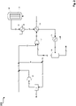
- a fresh gas stream 11 for example generated in a plant for autothermal reforming of natural gas (not shown), is combined with a hydrogen-containing stream 12, whereby a hydrogen-rich synthesis gas stream 13 with a stoichiometry number of 2.0 or greater is generated.
- the hydrogen-rich synthesis gas stream 13 is compressed by a compressor stage 30 to synthesis pressure.
- a portion of the hydrogen-rich synthesis gas stream 13 is separated off as a hydrogen-rich partial synthesis gas stream 14 and combined with a flushing gas stream 15 , resulting in a mixed synthesis gas stream 16 .
- the mixed synthesis gas stream 16 is fed to the hydrogen recovery stage 31, in which the hydrogen-containing stream 12 with a hydrogen content of at least 99% by volume is generated by alternating pressure absorption.
- Exhaust gas simultaneously generated in the hydrogen recovery stage 31 17, which contains carbon oxides and components that are inert under the conditions of methanol synthesis can be used, for example, as fuel gas in the reformer unit upstream of the methanol synthesis.
- the main part 18 of the hydrogen-rich synthesis gas stream compressed to synthesis pressure is combined with a residual gas stream 19 compressed to synthesis pressure in a compressor stage 32 .
- the resulting combined synthesis gas stream 20 is heated in a heat exchanger 33 and fed to a methanol reactor 34 as heated synthesis gas stream 21 .
- the methanol reactor 34 the conversion of the synthesis gas from synthesis gas stream 21 to methanol and water takes place on the methanol synthesis catalyst of the catalyst bed 35.
- the product stream 22 resulting from the reaction in reactor 34 which in addition to methanol and water also includes unreacted synthesis gas or residual gas, is then successively cooled via the heat exchangers 36, 33 and 37, with the product streams 23, 24 and 25 downstream of the respective heat exchangers result.
- the cooled product stream 25 is then separated in a separator 38 into a liquid phase comprising methanol and water and a gaseous phase comprising residual gas.
- the synthesis gas or residual gas that has not been converted in the reactor 34 is drawn off as residual gas stream 26 from the separator 38 .
- a crude methanol stream 27 comprising methanol and water is drawn off from the separator 38 and fed to further processing, for example a rectification (not shown).
- the flushing gas stream 15 is separated from the residual gas stream 26 and a remaining residual gas stream 28 is compressed in the compressor stage 32 to synthesis pressure. Residual gas stream 19 compressed to synthesis pressure is in turn combined with hydrogen-rich synthesis gas stream 18 and again fed to the conversion to methanol in the methanol reactor 34 .
- figure 2 shows a compared to the example of figure 1 modified type of process management according to a further example of the invention.
- the hydrogen-containing stream 12 generated in the hydrogen recovery stage 31 is compressed in a hydrogen compressor 40, wherein a compressed hydrogen-containing stream 51 is obtained, which is combined with the fresh gas stream 11.
- a hydrogen-rich synthesis gas stream 13 the main part 18 of which is fed to the compressor stage 41 for compression to synthesis pressure and part of which is branched off as a hydrogen-rich synthesis gas partial stream 14 and combined with the purge gas stream 15.
- the mixed synthesis gas stream 16 results from the streams 14 and 15 .
- the hydrogen-rich synthesis gas stream 18 and the residual gas stream are fed together to a compressor stage 41 .
- Compressor stage 41 has two nozzles on the suction side, which enables the simultaneous compression of the hydrogen-rich synthesis gas stream 18 and the residual gas stream 28, with the combined synthesis gas stream 20 being obtained, which is heated in the heat exchanger 33 and fed to the methanol reactor 34 as the synthesis gas stream 21.
- FIG 3 shows a type of process control known from the prior art.
- the hydrogen recovery stage 31 is also fed a mixed gas stream of synthesis gas and purge gas and used for hydrogen recovery.
- the synthesis gas portion of the mixed gas flow is a partial fresh gas flow 60 which is branched off from the (main) fresh gas flow 11 with the aid of the throttle element 70 .
- the partial make-up gas stream 60 and the purge gas stream 15 are combined and fed to the hydrogen recovery stage 31 as a mixed synthesis gas stream 61 .
- the mixed synthesis gas flow 61 is accordingly not generated from synthesis gas already enriched with hydrogen and flushing gas, but from fresh gas and flushing gas.
- this type of process procedure has disadvantages compared to the process according to the invention.
- a disadvantage results from the inevitable use of the throttling element 70 required for throttling the (main) fresh gas flow 11 .
- Example 1 is based on the procedure according to figure 1 , in comparison with the procedure according to the state of the art ( figure 3 - comparative example).
- the low-hydrogen synthesis gas stream or fresh gas stream (11) has the following composition according to Example 1 and Comparative Example: component Percentage (vol%) water 0.21 carbon dioxide 8.04 carbon monoxide 23:16 hydrogen 65.94 argon 0.12 nitrogen 0.52 methane 2.01
- Argon, nitrogen and methane are inert gas components under the conditions of methanol synthesis and are essentially removed from the synthesis circuit via the flushing gas stream (15).
- the hydrogen-rich synthesis gas stream (13, 18) has the following composition: component Percentage (vol%) water 0.19 carbon dioxide 7.54 carbon monoxide 21.71 hydrogen 68.07 argon 0.11 nitrogen 0.49 methane 1.89
- the amount of substance flow of hydrogen-rich synthesis gas fed to the hydrogen recovery stage (31) (share 14 in the total flow of the hydrogen-rich synthesis gas) is 1451.5 kmol/h.
- the mass flow of the flushing gas flow (15) is 1306.3 kmol/h.
- Both streams together form the mixed synthesis gas stream (16) with a molar flow rate of 2757.8 kmol/h. For Example 1, this results in a molar flow fraction or molar fraction of the hydrogen-rich synthesis gas flow in the mixed synthesis gas flow of 0.53.
- the amount of substance flow fraction or amount of substance fraction of the part (14) separated from the hydrogen-rich synthesis gas stream in relation to the total amount of substance flow of hydrogen-rich synthesis gas (13) is, according to example 1, 0.059.
- Example 2 is based on the procedure according to figure 2 , in comparison with the procedure according to the state of the art ( figure 3 - comparative example).
- the low-hydrogen synthesis gas stream or fresh gas stream (11) has the following composition according to Example 2 and Comparative Example: component Percentage (vol%) water 0.16 carbon dioxide 7.54 carbon monoxide 24.68 hydrogen 65.55 argon 0.12 nitrogen 0.09 methane 1.86
- the hydrogen-rich synthesis gas stream (13, 18) has the following composition: component Percentage (vol%) water 0.14 carbon dioxide 6.99 carbon monoxide 22.84 hydrogen 68:12 argon 0.11 nitrogen 0.08 methane 1.72
- the amount of substance flow of hydrogen-rich synthesis gas fed to the hydrogen recovery stage (31) (share 14 in the total flow of the hydrogen-rich synthesis gas) is 2280.0 kmol/hr.
- the mass flow of the flushing gas flow (15) is 976.4 kmol/hr.
- Both streams together form the mixed synthesis gas stream (16) with a molar flow rate of 3256.4 kmol/hr. For Example 2, this results in a molar flow fraction or molar fraction of the hydrogen-rich synthesis gas stream in the mixed synthesis gas stream of 0.70.
- the amount of substance flow fraction or amount of substance fraction of the part (14) separated from the hydrogen-rich synthesis gas stream in relation to the total amount of substance flow of hydrogen-rich synthesis gas (13) is, according to example 2, 0.091.
Description
Die Erfindung betrifft ein Verfahren sowie eine Anlage zur Herstellung von Methanol aus einem wasserstoffarmen Frischgasstrom, wobei dem wasserstoffarmen Frischgasstrom ein wasserstoffhaltiger Strom zugeführt wird, so dass ein wasserstoffreicher Synthesegasstrom mit einer Stöchiometriezahl von 2.0 oder größer erhalten wird. Die Erfindung betrifft ferner die Verwendung des erfindungsgemäßen Verfahrens oder der erfindungsgemäßen Anlage zur Herstellung von Methanol aus durch autotherme Reformierung und/oder partielle Oxidation erzeugtem Frischgas.The invention relates to a method and a plant for producing methanol from a hydrogen-poor fresh gas stream, a hydrogen-containing stream being fed to the hydrogen-poor fresh gas stream so that a hydrogen-rich synthesis gas stream with a stoichiometry number of 2.0 or greater is obtained. The invention also relates to the use of the method according to the invention or the plant according to the invention for the production of methanol from fresh gas produced by autothermal reforming and/or partial oxidation.
Methanol wird im großtechnischen Maßstab aus Synthesegas hergestellt. Synthesegas ist ein Gemisch aus vorwiegend Wasserstoff (H2), Kohlenmonoxid (CO) sowie Kohlendioxid (CO2). Darüber hinaus weist es kleinere Mengen an unter den Bedingungen der Methanolsynthese inerten Gasbestandteilen auf. Kohlenmonoxid sowie Kohlendioxid werden dabei häufig unter dem Begriff "Kohlenoxide" oder "Kohlenstoffoxide" zusammengefasst. Im heute als Niederdruck-Methanolsynthese bezeichneten Prozess wird das Synthesegas bei einem Synthesedruck von 60 bis 120 bar zu Methanol und Wasser (als zwangsläufig anfallendes Nebenprodukt) umgesetzt. Das eingesetzte Synthesegas, häufig als Frischgas bezeichnet, wird dabei nach Verdichtung auf den jeweiligen Synthesedruck bei Katalysator-Temperaturen von üblicherweise größer als 200 °C durch ein Katalysatorbett eines Methanolsynthese-Katalysators geleitet. Bei dem Methanolsynthese-Katalysator handelt es sich üblicherweise um eine als katalytisch aktive Spezies Kupfer aufweisende Zusammensetzung. Je nach Verfahrensführung kommen eine oder mehrere hintereinander oder parallel geschaltete Reaktoren zum Einsatz, welche jeweils über ein entsprechendes Katalysatorbett verfügen. Dabei ist die Umsetzung der Kohlenstoffoxide zu Methanol und Wasser am Katalysator aufgrund der Einstellung eines thermodynamischen Gleichgewichts gemäß der Reaktionen
![]()
![]()
![]()
![]()
Die Zusammensetzung des Frischgases oder eines Synthesegases im Allgemeinen ist durch die sogenannte Stöchiometriezahl SN, definiert als ![]()
![]()
Werte von kleiner als 2,0 weisen auf ein Wasserstoffdefizit hin, während Werte von größer als 2,0 auf einen Wasserstoffüberschuss hinweisen.Values less than 2.0 indicate a hydrogen deficit, while values greater than 2.0 indicate a hydrogen excess.
Synthesegase mit Wasserstoffdefizit werden beispielsweise bei Prozessen, welche einen partiellen Oxidationsschritt umfassen, oder bei der Erzeugung von Synthesegas durch Kohlevergasung, erhalten. In einem solchen Fall wird der Wasserstoff bei der Methanolsynthese nahezu vollständig verbraucht, während ein wesentlicher Teil der Kohlenstoffoxide nicht umgesetzt wird. Dies führt zu einer Zusammensetzung in der Syntheseschleife, welche sich durch hohe Anteile an Kohlenstoffoxiden, jedoch einen niedrigen Anteil an Wasserstoff auszeichnen. Dies hat unter anderem zur Folge, dass der Methanolsynthese-Reaktor mit einem hohen Katalysatorvolumen auszulegen ist und dass der Gehalt an Nebenprodukten (insbesondere höhere Alkohole und Ketone) höher ist als erwünscht.Hydrogen-deficient synthesis gases are obtained, for example, from processes which include a partial oxidation step or from the production of synthesis gas by coal gasification. In such a case, the hydrogen is almost completely consumed in the methanol synthesis, while a substantial part of the carbon oxides is not converted. This leads to a composition in the synthesis loop characterized by a high proportion of carbon oxides but a low proportion of hydrogen. One of the consequences of this is that the methanol synthesis reactor has to be designed with a high catalyst volume and that the content of by-products (in particular higher alcohols and ketones) is higher than desired.
Um auch wasserstoffarmes Synthesegas sinnvoll großtechnisch bei der Methanolherstellung verwenden zu können, kann das Synthesegas beispielsweise durch Wasserstoff aus einer Wasserstoffrückgewinnungsanlage auf die gewünschte Stöchiometriezahl von zwei oder größer eingestellt werden. Dies ist beispielsweise durch Wasserstoffrückgewinnung aus dem Spülstrom möglich.In order to also be able to use hydrogen-poor synthesis gas on an industrial scale in the production of methanol, the synthesis gas can be adjusted to the desired stoichiometry number of two or greater, for example by means of hydrogen from a hydrogen recovery plant. This is possible, for example, by recovering hydrogen from the purge flow.
Die aus dem Teilstrom des nicht umgesetzten Synthesegases zu gewinnenden Wasserstoffmengen sind jedoch häufig nicht ausreichend, um ein Synthesegas mit ausreichend hoher Stöchiometriezahl zu erhalten. Beispielsweise können Synthesegase mit einem hohen Wasserstoffdefizit einen so hohen Spülstrom-Anteil zur Wasserstoffrückgewinnung erfordern, dass die Syntheseschleife entweder bei niedrigen Drücken betrieben werden muss oder dass das Verhältnis des Rückführgasstroms zum Frischgasstrom niedrig eingestellt werden muss.However, the amounts of hydrogen to be obtained from the substream of the unreacted synthesis gas are often not sufficient to obtain a synthesis gas with a sufficiently high stoichiometry number. For example, synthesis gases with a high hydrogen deficit may require such a high proportion of hydrogen recovery purge flow that the synthesis loop must either be operated at low pressures or that the ratio of recycle gas flow to make-up gas flow must be set low.
Um diesen Nachteilen zu begegnen, ist auch denkbar einen Teil des Frischgases vor der Methanolsynthese abzuzweigen und einer Wasserstoffrückgewinnungsstufe zuzuführen. Der Nachteil dieser Anordnung besteht darin, dass ein Teil des Wasserstoffs in der Wasserstoffrückgewinnungsstufe verloren geht, bevor er in den Synthesekreislauf gelangt. Weiterhin weist das Synthesegas nach der Anreicherung mit diesem Wasserstoff eine Stöchiometriezahl von größer als zwei auf, was dazu führen kann, dass der in diesem Fall nicht genutzte Spülgasstrom zu einem erheblichen Teil nicht umgesetzten Wasserstoff aufweisen kann.In order to counteract these disadvantages, it is also conceivable to branch off part of the fresh gas before the methanol synthesis and feed it to a hydrogen recovery stage. The disadvantage of this arrangement is that some of the hydrogen is lost in the hydrogen recovery stage before entering the synthesis loop. Furthermore, after enrichment with this hydrogen, the synthesis gas has a stoichiometry number of greater than two, which can result in the flushing gas flow not used in this case having a significant proportion of unreacted hydrogen.
Eine Aufgabe der vorliegenden Erfindung besteht darin ein Verfahren und eine Anlage zur Herstellung von Methanol bereitzustellen, welches die Nachteile des Standes der Technik zumindest teilweise überwindet. Insbesondere besteht eine Aufgabe der vorliegenden Erfindung darin ein Verfahren und eine Anlage bereitzustellen, welches keine Drosselung des Hauptfrischgasstroms durch eine Druckminderungsvorrichtung erfordert.One object of the present invention is to provide a method and a plant for the production of methanol, which at least partially overcomes the disadvantages of the prior art. In particular, it is an object of the present invention to provide a method and a system which do not require the main fresh gas flow to be throttled by a pressure-reducing device.
Ein Beitrag zur mindestens teilweisen Erfüllung mindestens einer der obigen Aufgaben wird durch die unabhängigen Ansprüche geleistet. Die abhängigen Ansprüche stellen bevorzugte Ausführungsformen bereit, die zur mindestens teilweisen Erfüllung mindestens einer der Aufgaben beitragen. Bevorzugte Ausgestaltungen von Bestandteilen einer erfindungsgemäßen Kategorie sind, soweit zutreffend, ebenso bevorzugt für gleichnamige oder entsprechende Bestandteile einer jeweils anderen erfindungsgemäßen Kategorie.A contribution to at least partially fulfilling at least one of the above objects is made by the independent claims. The dependent claims provide preferred embodiments contributing to at least partly fulfilling at least one of the objects. Preferred configurations of components of a category according to the invention are, if applicable, also preferred for components of the same name or corresponding components of a different category according to the invention.
Die Ausdrücke "aufweisend", "umfassend" oder "beinhaltend" etc. schließen nicht aus, dass weitere Elemente, Inhaltsstoffe etc. enthalten sein können. Der unbestimmte Artikel "ein" schließt nicht aus, dass eine Mehrzahl vorhanden sein kann.The terms "comprising", "comprising" or "including" etc. do not exclude that further elements, ingredients etc. can be included. The indefinite article "a" does not exclude that a plural number can be present.
Die vorgenannten Aufgaben werden zumindest teilweise gelöst durch ein Verfahren zur Herstellung von Methanol, wobei einem Frischgasstrom aus einer Reformereinheit, welcher Wasserstoff und Kohlenoxide umfasst, ein wasserstoffhaltiger Strom aus einer Wasserstoffrückgewinnungsstufe zugeführt wird, wobei ein wasserstoffreicher Synthesegasstrom mit einer Stöchiometriezahl SN, definiert als SN = [n(H2)-n(CO2)] / [n(CO) + n(CO2)], von 2.0 oder größer erhalten wird, und wobei der wasserstoffreiche Synthesegasstrom mit einem Restgasstrom zusammengeführt und der wasserstoffreiche Synthesegasstrom und der Restgasstrom bei erhöhtem Druck und erhöhter Temperatur durch ein Bett eines Methanolsynthese-Katalysators geleitet werden, wobei ein Produktstrom erhalten wird, welcher Methanol und den Restgasstrom umfasst, und wobei der Produktstrom gekühlt wird um Methanol vom Restgasstrom abzutrennen. Erfindungsgemäß ist vorgesehen, dass von dem Restgasstrom ein Teil als Spülgasstrom abgetrennt wird und von dem wasserstoffreichen Synthesegasstrom ein Teil abgetrennt und mit dem Spülgasstrom zusammengeführt wird, wobei ein gemischter Synthesegasstrom erhalten wird, und der gemischte Synthesegasstrom der Wasserstoffrückgewinnungsstufe zur Erzeugung des wasserstoffhaltigen Stroms zugeführt wird.The above objects are at least partially achieved by a process for the production of methanol, a fresh gas stream from a reformer unit, which comprises hydrogen and carbon oxides, being supplied with a hydrogen-containing stream from a hydrogen recovery stage, with a hydrogen-rich synthesis gas stream having a stoichiometry number SN, defined as SN= [n(H 2 )-n(CO 2 )] / [n(CO) + n(CO 2 )], of 2.0 or greater, and wherein the hydrogen-rich syngas stream is combined with a tail gas stream and the hydrogen-rich syn gas stream and the tail gas stream are passed through a bed of a methanol synthesis catalyst at elevated pressure and elevated temperature, a product stream being obtained which comprises methanol and the tail gas stream, and the product stream being cooled in order to separate methanol from the tail gas stream. According to the invention, part of the residual gas stream is separated off as a flushing gas stream and part of the hydrogen-rich synthesis gas stream is separated off and combined with the flushing gas stream, a mixed synthesis gas stream being obtained, and the mixed synthesis gas stream being fed to the hydrogen recovery stage to generate the hydrogen-containing stream.
Erfindungsgemäß wird nicht der Frischgasstrom und der aus dem Restgasstrom abgezweigte Spülgasstrom der Wasserstoffrückgewinnungsstufe zugeführt, sondern der bereits mit Wasserstoff auf eine Stöchiometriezahl von 2.0 oder größer eingestellte wasserstoffreiche Synthesegasstrom wird zusammen mit dem Spülgasstrom der Wasserstoffrückgewinnungsstufe zugeführt. Dadurch kann auf eine Drosselung des Frischgasstroms zum Abzweigen eines Teils des Frischgasstroms in Richtung der Wasserstoffrückgewinnungsstufe verzichtet werden. Ferner haben Untersuchungen gezeigt, dass durch die erfindungsgemäße Verfahrensführung Einsparungen in Bezug auf die aufzuwendende Kompressionsenergie erzielt werden können.According to the invention, the fresh gas stream and the purge gas stream branched off from the residual gas stream are not fed to the hydrogen recovery stage, but rather the hydrogen-rich synthesis gas stream, which has already been adjusted with hydrogen to a stoichiometry number of 2.0 or greater, is fed to the hydrogen recovery stage together with the purge gas stream. As a result, a throttling of the fresh gas flow in order to divert part of the fresh gas flow in the direction of the hydrogen recovery stage can be dispensed with. Furthermore, investigations have shown that savings in relation to the compression energy to be used can be achieved by the process management according to the invention.
Bei dem Frischgasstrom handelt es sich vorzugsweise um einen Synthesegasstrom aus einer Reformereinheit, welcher sich insbesondere durch ein Defizit an Wasserstoff auszeichnet, so dass die Stöchiometriezahl des Frischgases insbesondere bei kleiner als 2.0 liegt. Ein solcher Frischgasstrom wird insbesondere in einer Reformereinheit erzeugt, welche zur Erzeugung des Synthesegases einen partiellen Oxidationsschritt eines kohlenstoffhaltigen Einsatzgases umfasst. Beispielsweise kann der Frischgasstrom aus autothermer Reformierung eines kohlenstoffhaltigen Einsatzgases erzeugt werden. Bei dem Einsatzgas handelt es sich vorzugsweise um Erdgas. Ferner kann der Frischgasstrom aus Kohlevergasung erzeugt werden. Der Frischgasstrom wird vor dem Zuführen des wasserstoffhaltigen Stroms und Verdichtung auf Synthesedruck, zur Kondensation und Abtrennung von Wasser, auf eine Temperatur von vorzugsweise 40 °C oder weniger abgekühlt. Der Frischgasstrom weist üblicherweise einen Druck zwischen 35 und 60 bar auf, weshalb vor der Umsetzung am Methanolsynthese-Katalysator eine zusätzliche Verdichtung auf Synthesedruck erforderlich ist.The fresh gas flow is preferably a synthesis gas flow from a reformer unit, which is characterized in particular by a hydrogen deficit, so that the stoichiometry number of the fresh gas is in particular less than 2.0. Such a fresh gas stream is generated in particular in a reformer unit, which includes a partial oxidation step of a carbon-containing feed gas to generate the synthesis gas. For example, the fresh gas stream can be generated from autothermal reforming of a carbonaceous feed gas. The feed gas is preferably natural gas. Furthermore, the fresh gas stream can be generated from coal gasification. Before the hydrogen-containing stream is fed in and compressed to synthesis pressure, the fresh gas stream is cooled to a temperature of preferably 40° C. or less for condensation and removal of water. The fresh gas stream usually has a pressure of between 35 and 60 bar, which is why additional compression to synthesis pressure is required before the reaction on the methanol synthesis catalyst.
Eine Reformereinheit kann eine Einheit zur Umwandlung (Reformierung) eines gasförmigen kohlenstoffhaltigen Einsatzstoffes oder eines festen kohlenstoffhaltigen Einsatzstoffes umfassen. Ein Beispiel für einen gasförmigen kohlenstoffhaltigen Einsatzstoff ist Erdgas. Beispiele für feste kohlenstoffhaltige Einsatzstoffe sind Kohle, feste Abfälle (Müll) und Biomasse.A reformer unit may comprise a unit for converting (reforming) a gaseous carbonaceous feedstock or a solid carbonaceous feedstock. An example of a gaseous carbonaceous feedstock is natural gas. Examples of solid carbonaceous feedstocks are coal, solid waste (garbage) and biomass.
Der wasserstoffhaltige Strom weist vorzugsweise einen Wasserstoff-Gehalt von 95 Vol.-% oder mehr auf. Angestrebt wird ein wasserstoffhaltiger Strom, welcher reinen oder im Wesentlichen reinen Wasserstoff enthält. Außer dem wasserstoffhaltigen Strom wird durch die Wasserstoffrückgewinnungsstufe auch ein Abgasstrom erzeugt, welcher unter den Bedingungen der Methanolsynthese inerte Bestandteile sowie kleinere Mengen an nicht umgesetzten Kohlenoxiden umfasst.The hydrogen-containing stream preferably has a hydrogen content of 95% by volume or more. The aim is a hydrogen-containing stream which contains pure or essentially pure hydrogen. In addition to the hydrogen-containing stream, the hydrogen recovery stage also produces a waste gas stream which comprises components which are inert under the conditions of the methanol synthesis and also small amounts of unreacted carbon oxides.
Am Methanolsynthese-Katalysator erfolgt die Umsetzung des wasserstoffreichen Synthesegasstroms und des Restgasstroms zu Methanol (und Wasser). Die Umsetzung erfolgt in einer Syntheseschleife, das heißt am Katalysator nicht umgesetztes Synthesegas wird als Restgasstrom zum Eingang des betreffenden Reaktors zurückgeführt (recycelt) und am Methanolsynthese-Katalysator zusammen mit erstmalig verwendetem wasserstoffreichem Synthesegas zu Methanol umgesetzt. Die Umsetzung am Methanolsynthese-Katalysator erfolgt vorzugsweise bei einer Katalysatortemperatur von 220 °C bis 270 °C und vorzugsweise einem Druck von 55 bar bis 80 bar. Die Umsetzung am Methanolsynthese-Katalysator findet vorzugsweise in einer oder mehreren hintereinander oder parallel geschalteten Reaktorstufen statt, wobei jede der Reaktorstufen ein entsprechendes Katalysatorbett umfasst. Insbesondere umfassen die Reaktorstufen einen wassergekühlten Reaktor und einen dem wassergekühlten Reaktor nachgeschalteten gasgekühlten Reaktor. Geeignete Katalysatoren sind aus dem Stand der Technik bekannte Materialien auf Kupfer-Basis mit Kupfer als katalytisch aktiver Spezies, ein Beispiel hierfür ist eine Katalysator-Zusammensetzung welche Kupfer, Zinkoxid sowie Aluminiumoxid umfasst.The conversion of the hydrogen-rich synthesis gas stream and the residual gas stream to methanol (and water) takes place at the methanol synthesis catalyst. The reaction takes place in a synthesis loop, ie what is not reacted on the catalyst Synthesis gas is fed back (recycled) as a residual gas stream to the inlet of the relevant reactor and converted to methanol on the methanol synthesis catalyst together with the hydrogen-rich synthesis gas used for the first time. The reaction over the methanol synthesis catalyst preferably takes place at a catalyst temperature of from 220° C. to 270° C. and preferably at a pressure of from 55 bar to 80 bar. The reaction over the methanol synthesis catalyst preferably takes place in one or more reactor stages connected in series or in parallel, each of the reactor stages comprising a corresponding catalyst bed. In particular, the reactor stages comprise a water-cooled reactor and a gas-cooled reactor downstream of the water-cooled reactor. Suitable catalysts are copper-based materials known from the prior art with copper as the catalytically active species, an example of this is a catalyst composition which comprises copper, zinc oxide and aluminum oxide.
Eine bevorzugte Ausführungsform des erfindungsgemäßen Verfahrens ist dadurch gekennzeichnet, dass der wasserstoffreiche Synthesegasstrom verdichtet wird, und von dem verdichteten wasserstoffreichen Synthesegasstrom ein Teil abgetrennt und mit dem Spülgasstrom zusammengeführt wird. Vorzugsweise wird der wasserstoffreiche Synthesegasstrom auf Synthesedruck verdichtet. Vorzugsweise wird der wasserstoffreiche Synthesegasstrom auf einen Druck von 70 bar oder mehr, und bis zu einem Druck von 90 bar verdichtet. Wie Untersuchungen gezeigt haben und im Detail weiter unten ausgeführt, werden durch diese Art der Verfahrensführung Einsparungen bei der benötigten Kompressionsenergie erzielt. Vorzugsweise wird in diesem Zusammenhang der Restgasstrom verdichtet und mit dem verdichteten wasserstoffreichen Synthesegasstrom zusammengeführt, und die zusammengeführten Ströme werden durch das Bett des Methanolsynthese-Katalysators geleitet. Der Spülgasstrom wird insbesondere vor der Verdichtung des Restgasstroms von dem Restgasstrom abgezweigt. Vorzugsweise wird der Restgasstrom auf Synthesedruck verdichtet. Vorzugsweise wird der Restgasstrom dabei auf einen Druck von 70 bar oder mehr, und bis zu einem Druck von 90 bar verdichtet.A preferred embodiment of the method according to the invention is characterized in that the hydrogen-rich synthesis gas stream is compressed and a portion of the compressed hydrogen-rich synthesis gas stream is separated and combined with the flushing gas stream. The hydrogen-rich synthesis gas stream is preferably compressed to synthesis pressure. Preferably, the hydrogen-rich synthesis gas stream is compressed to a pressure of 70 bar or more and up to a pressure of 90 bar. As investigations have shown and explained in detail below, savings in the required compression energy are achieved by this type of process control. Preferably in this regard the tail gas stream is compressed and combined with the compressed hydrogen-rich synthesis gas stream and the combined streams are passed through the methanol synthesis catalyst bed. The flushing gas flow is branched off from the residual gas flow, in particular before the residual gas flow is compressed. The residual gas stream is preferably compressed to synthesis pressure. The residual gas stream is preferably compressed to a pressure of 70 bar or more and up to a pressure of 90 bar.
Eine bevorzugte Ausführungsform des erfindungsgemäßen Verfahrens ist dadurch gekennzeichnet, dass der wasserstoffhaltige Strom durch einen Wasserstoffkompressor verdichtet wird, und der verdichtete wasserstoffhaltige Strom mit dem Frischgasstrom zusammengeführt wird, wobei der wasserstoffreiche Synthesegasstrom erhalten wird, und von dem wasserstoffreichen Synthesegasstrom ein Teil abgetrennt und mit dem Spülgasstrom zusammengeführt wird. Wie Untersuchungen gezeigt haben und weiter unten ausgeführt, werden durch diese Art der Verfahrensführung Einsparungen bei der benötigten Kompressionsenergie erzielt. Der wasserstoffhaltige Strom wird durch den Wasserstoffkompressor auf einen Druck verdichtet, welcher in etwa 1 bis 2 bar oberhalb des Drucks des Frischgases (ca. 35 bis 60 bar) liegt. Vorzugsweise werden in diesem Zusammenhang der wasserstoffreiche Synthesegasstrom und der Restgasstrom gemeinsam verdichtet und durch das Bett des Methanolsynthese-Katalysators geleitet. Vorzugsweise werden der wasserstoffreiche Synthesegasstrom und der Restgasstrom gemeinsam auf Synthesedruck verdichtet. Insbesondere werden der wasserstoffreiche Synthesegasstrom und der Restgasstrom dabei gemeinsam auf einen Druck von 70 bar oder mehr und bis zu einem Druck von 90 bar verdichtet. Der Spülgasstrom wird dabei zwangsläufig vor der gemeinsamen Verdichtung des Restgasstroms und des wasserstoffreichen Synthesegasstroms von dem Restgasstrom abgezweigt.A preferred embodiment of the method according to the invention is characterized in that the hydrogen-containing stream is compressed by a hydrogen compressor, and the compressed hydrogen-containing stream is combined with the fresh gas stream, the hydrogen-rich synthesis gas stream being obtained, and a portion of the hydrogen-rich synthesis gas stream is separated and combined with the purge gas stream is merged. As investigations have shown and explained further below, savings in the required compression energy are achieved by this type of process control. The hydrogen-containing stream is compressed by the hydrogen compressor to a pressure which is approximately 1 to 2 bar above the pressure of the fresh gas (approx. 35 to 60 bar). In this context, the hydrogen-rich synthesis gas stream and the residual gas stream are preferably compressed together and passed through the bed of the methanol synthesis catalyst. The hydrogen-rich synthesis gas stream and the residual gas stream are preferably compressed together to synthesis pressure. In particular, the hydrogen-rich synthesis gas stream and the residual gas stream are compressed together to a pressure of 70 bar or more and up to a pressure of 90 bar. The flushing gas stream is inevitably branched off from the residual gas stream before the common compression of the residual gas stream and the hydrogen-rich synthesis gas stream.
Eine bevorzugte Ausführungsform des erfindungsgemäßen Verfahrens ist dadurch gekennzeichnet, dass der Stoffmengenstrom-Anteil des wasserstoffreichen Synthesegasstroms am gemischten Synthesegasstrom zwischen 0,10 und 0,95 liegt, bevorzugt zwischen 0,20 und 0,90 liegt, weiter bevorzugt zwischen 0,30 und 0,80 liegt und weiter bevorzugt zwischen 0,50 und 0,75 liegt.A preferred embodiment of the method according to the invention is characterized in that the mass flow fraction of the hydrogen-rich synthesis gas flow in the mixed synthesis gas flow is between 0.10 and 0.95, preferably between 0.20 and 0.90, more preferably between 0.30 and 0 .80 and more preferably between 0.50 and 0.75.
Der Stoffmengenstrom kann beispielsweise durch die Einheit "kmol/h" (kilomol pro Stunde) wiedergegeben werden.The mass flow rate can be represented, for example, by the unit “kmol/h” (kilomoles per hour).
Eine bevorzugte Ausführungsform des erfindungsgemäßen Verfahrens ist dadurch gekennzeichnet, dass der Stoffmengenstrom-Anteil des vom wasserstoffreichen Synthesegasstrom abgetrennten Teils in Bezug auf den gesamten Stoffmengenstrom an wasserstoffreichem Synthesegas zwischen 0,001 und 0,999 liegt, vorzugsweise zwischen 0,005 und 0,800 liegt, weiter bevorzugt zwischen 0,010 und 0,500 liegt, weiter bevorzugt zwischen 0,020 und 0,200 liegt und weiter bevorzugt zwischen 0,050 und 0,100 liegt.A preferred embodiment of the method according to the invention is characterized in that the mass flow fraction of the part separated from the hydrogen-rich synthesis gas flow in relation to the total mass flow of hydrogen-rich synthesis gas is between 0.001 and 0.999, preferably between 0.005 and 0.800, more preferably between 0.010 and 0.500, more preferably between 0.020 and 0.200 and more preferably between 0.050 and 0.100.
Eine bevorzugte Ausführungsform des erfindungsgemäßen Verfahrens ist dadurch gekennzeichnet, dass der wasserstoffreiche Synthesegasstrom eine Stöchiometriezahl SN von 2,00 bis 2,20 aufweist, bevorzugt von 2,02 bis 2,10 aufweist, und weiter bevorzugt von 2,05 bis 2,07 aufweist.A preferred embodiment of the method according to the invention is characterized in that the hydrogen-rich synthesis gas stream has a stoichiometry number SN from 2.00 to 2.20, preferably from 2.02 to 2.10, and more preferably from 2.05 to 2.07 .
Eine bevorzugte Ausführungsform des erfindungsgemäßen Verfahrens ist dadurch gekennzeichnet, dass der Frischgasstrom eine Stöchiometriezahl SN von kleiner als 2,0 aufweist, bevorzugt von 1,70 bis 1,95 aufweist, weiter bevorzugt von 1,75 bis 1,90 aufweist, und weiter bevorzugt von 1,78 bis 1,85 aufweist. Synthesegas aus autothermer Reformierung weist häufig eine Stöchiometriezahl um 1,80 auf.A preferred embodiment of the method according to the invention is characterized in that the fresh gas stream has a stoichiometry SN of less than 2.0, preferably from 1.70 to 1.95, more preferably from 1.75 to 1.90, and more preferably from 1.78 to 1.85. Synthesis gas from autothermal reforming often has a stoichiometry number around 1.80.
Eine bevorzugte Ausführungsform des erfindungsgemäßen Verfahrens ist dadurch gekennzeichnet, dass die Wasserstoffrückgewinnungsstufe eine Wechseldruckabsorptionsvorrichtung zur Abtrennung von Wasserstoff aus dem gemischten Synthesegasstrom umfasst. Durch eine Wechseldruckabsorptionsvorrichtung kann reiner oder zumindest nahezu reiner Wasserstoff bei hohen Drücken, beispielsweise bei 40 bis 60 bar, erzeugt werden. Wird Wasserstoff bereits bei hohem Druck durch die Wasserstoffrückgewinnungsstufe bereitgestellt, können nachfolgend angeordnete Verdichterstufen, beispielsweise zur Verdichtung von Wasserstoff (Wasserstoffkompressor) oder zur Verdichtung des wasserstoffreichen Synthesegasstroms entsprechend kleiner ausgelegt werden. Ferner steigt die Konzentration an inerten Bestandteilen in der Syntheseschleife umso langsamer an, je höher die Reinheit des in der Wasserstoffrückgewinnungsstufe erzeugten Wasserstoffs ist.A preferred embodiment of the process according to the invention is characterized in that the hydrogen recovery stage comprises an alternating pressure absorption device for separating hydrogen from the mixed synthesis gas stream. Pure or at least almost pure hydrogen can be generated at high pressures, for example at 40 to 60 bar, by means of an alternating pressure absorption device. If hydrogen is already provided at high pressure by the hydrogen recovery stage, downstream compressor stages, for example for compressing hydrogen (hydrogen compressor) or for compressing the hydrogen-rich synthesis gas stream, can be designed correspondingly smaller. Furthermore, the higher the purity of the hydrogen produced in the hydrogen recovery stage, the slower the increase in the concentration of inerts in the synthesis loop.
Alternativ zu einer Wechseldruckabsorptionsvorrichtung kann die Wasserstoffrückgewinnungsstufe auch eine Membrantrennstufe zur Abtrennung von Wasserstoff aus dem gemischten Synthesegasstrom umfassen. Ebenso denkbar sind Kombinationen aus einer oder mehreren Wechseldruckabsorptionsvorrichtungen und einer oder mehreren Membrantrennstufen.As an alternative to an alternating pressure absorption device, the hydrogen recovery stage may also include a membrane separation stage for separating hydrogen from the mixed synthesis gas stream. Combinations of one or more alternating pressure absorption devices and one or more membrane separation stages are also conceivable.
Eine bevorzugte Ausführungsform des erfindungsgemäßen Verfahrens ist dadurch gekennzeichnet, dass der wasserstoffhaltige Strom einen Wasserstoffanteil von mindestens 95 Vol.-% aufweist, bevorzugt von mindestens 99 Vol.-% aufweist, weiter bevorzugt von mindestens 99,5 Vol.-% aufweist, weiter bevorzugt von mindestens 99,9 Vol.-% aufweist.A preferred embodiment of the process according to the invention is characterized in that the hydrogen-containing stream has a hydrogen content of at least 95% by volume, preferably at least 99% by volume, more preferably at least 99.5% by volume, more preferably of at least 99.9% by volume.
Die vorgenannten Aufgaben werden ferner zumindest teilweise gelöst durch eine Anlage zur Herstellung von Methanol, aufweisend folgende miteinander in Fluidverbindung stehende Anlagenkomponenten: Eine Reformereinheit zur Erzeugung eines Wasserstoff und Kohlenstoffoxide aufweisenden Frischgasstroms; eine Wasserstoffrückgewinnungsstufe zur Erzeugung eines wasserstoffhaltigen Stroms, wobei die Reformereinheit und die Wasserstoffrückgewinnungsstufe so konfiguriert sind, dass aus dem wasserstoffhaltigen Strom und dem Frischgasstrom ein wasserstoffreicher Synthesegasstrom mit einer Stöchiometriezahl SN, definiert als SN = [n(H2) - n(CO2)] / [n(CO) + n(CO2)], von 2.0 oder größer erhältlich ist; eine Reaktorstufe umfassend ein Methanolsynthese-Katalysatorbett, wobei die Reaktorstufe so konfiguriert ist, dass der wasserstoffreiche Synthesegasstrom sowie ein Restgasstrom bei erhöhtem Druck und erhöhter Temperatur durch das Methanolsynthese-Katalysatorbett hindurchgeleitet werden können, wodurch ein Produktstrom erhältlich ist, welcher Methanol und den Restgasstrom umfasst; eine Kühlvorrichtung zum Kühlen des Produktstroms, wobei die Kühlvorrichtung so konfiguriert ist, dass Methanol vom Restgasstrom abgetrennt werden kann. Erfindungsgemäß ist vorgesehen, dass die Anlage so konfiguriert ist, dass von dem Restgasstrom ein Teil als Spülgasstrom abgetrennt werden kann und von dem Synthesegasstrom ein Teil abgetrennt und mit dem Spülgasstrom zusammengeführt werden kann, wodurch ein gemischter Synthesegasstrom erhältlich ist, und der gemischte Synthesegasstrom der Wasserstoffrückgewinnungsstufe zur Erzeugung des wasserstoffhaltigen Stroms zugeführt werden kann.The aforementioned objects are also at least partially achieved by a plant for the production of methanol, having the following plant components which are in fluid communication with one another: a reformer unit for generating a fresh gas stream containing hydrogen and carbon oxides; a hydrogen recovery stage for producing a hydrogen-containing stream, wherein the reformer unit and the hydrogen recovery stage are configured such that from the hydrogen-containing stream and the make-up gas stream a hydrogen-rich synthesis gas stream having a stoichiometry number SN, defined as SN = [n(H 2 ) - n(CO 2 ) ] / [n(CO) + n(CO 2 )], from 2.0 or greater; a reactor stage comprising a methanol synthesis catalyst bed, the reactor stage being configured such that the hydrogen-rich synthesis gas stream and a tail gas stream can be passed through the methanol synthesis catalyst bed at elevated pressure and temperature, whereby a product stream comprising methanol and the tail gas stream is obtainable; a cooler for cooling the product stream, wherein the cooler is configured so that methanol can be separated from the residual gas stream. According to the invention, it is provided that the plant is configured in such a way that a part of the residual gas stream can be separated as a purge gas stream and a part of the synthesis gas stream can be separated and combined with the purge gas stream, whereby a mixed synthesis gas stream is obtainable, and the mixed synthesis gas stream of the hydrogen recovery stage can be supplied to generate the hydrogen-containing stream.
Die vorgenannten Aufgaben werden ferner zumindest teilweise gelöst durch die Verwendung des erfindungsgemäßen Verfahrens oder der erfindungsgemäßen Anlage zur Herstellung von Methanol aus durch autotherme Reformierung und/oder partielle Oxidation erzeugtem Frischgas.The aforementioned objects are also at least partially achieved by using the method according to the invention or the plant according to the invention for the production of methanol from fresh gas produced by autothermal reforming and/or partial oxidation.
Die Erfindung wird im Folgenden durch zwei erfindungsgemäße Beispiele sowie ein Vergleichsbeispiel näher erläutert, ohne den Gegenstand der Erfindung dadurch zu beschränken. Weitere Merkmale, Vorteile und Anwendungsmöglichkeiten der Erfindung ergeben sich aus der nachfolgenden Beschreibung der Ausführungsbeispiele in Zusammenhang mit den Zeichnungen und den Zahlenbeispielen.The invention is explained in more detail below by means of two examples according to the invention and a comparative example, without thereby restricting the subject matter of the invention. Further features, advantages and application possibilities of the invention result from the following description of the exemplary embodiments in connection with the drawings and the numerical examples.
Es zeigt
- Figur 1
- ein schematisches Blockfließbild eines Herstellverfahrens oder einer Anlage 100 für die Methanolsynthese gemäß einem ersten Ausführungsbeispiel der Erfindung,
- Figur 2
- ein schematisches Blockfließbild eines Herstellverfahrens oder einer Anlage 200 für die Methanolsynthese gemäß einem zweiten Ausführungsbeispiel der Erfindung,
- Figur 3
- ein schematisches Blockfließbild eines Herstellverfahrens oder einer Anlage 300 für die Synthese von Methanol gemäß Stand der Technik.
- figure 1
- a schematic block flow diagram of a manufacturing process or a
plant 100 for the methanol synthesis according to a first embodiment of the invention, - figure 2
- a schematic block flow diagram of a manufacturing process or a
plant 200 for the methanol synthesis according to a second embodiment of the invention, - figure 3
- a schematic block diagram of a manufacturing process or a
plant 300 for the synthesis of methanol according to the prior art.
Bei der Verfahrensführung gemäß
Der Hauptteil 18 des auf Synthesedruck verdichteten wasserstoffreichen Synthesegasstroms wird mit in einer Kompressorstufe 32 auf Synthesedruck verdichteten Restgasstrom 19 zusammengeführt. Der resultierende kombinierte Synthesegasstrom 20 wird in einem Wärmeaustauscher 33 aufgeheizt und als aufgeheizter Synthesegasstrom 21 einem Methanol-Reaktor 34 zugeführt. Im Methanol-Reaktor 34 findet die Umsetzung des Synthesegases aus Synthesegasstrom 21 am Methanolsynthese-Katalysator des Katalysatorbetts 35 zu Methanol und Wasser statt. Der aus der Umsetzung im Reaktor 34 resultierende Produktstrom 22, welcher neben Methanol und Wasser auch nicht reagiertes Synthesegas oder Restgas umfasst, wird anschließend nacheinander über die Wärmeaustauscher 36, 33 und 37 gekühlt, wobei den jeweiligen Wärmeaustauschern nachgeschaltet jeweils die Produktströme 23, 24 und 25 resultieren. Anschließend erfolgt in einem Abscheider 38 die Trennung des gekühlten Produktstroms 25 in eine Methanol und Wasser aufweisende flüssige Phase sowie eine Restgas umfassende gasförmige Phase. Aus dem Abscheider 38 wird das nicht im Reaktor 34 umgesetzte Synthesegas oder Restgas als Restgasstrom 26 abgezogen. Gleichzeitig wird ein Methanol und Wasser aufweisender Rohmethanolstrom 27 aus dem Abscheider 38 abgezogen und der weiteren Aufarbeitung, beispielsweise einer Rektifikation (nicht gezeigt), zugeführt. Von dem Restgasstrom 26 wird der Spülgasstrom 15 abgetrennt und ein verbleibender Restgasstrom 28 in der Kompressorstufe 32 auf Synthesedruck verdichtet. Auf Synthesedruck verdichteter Restgasstrom 19 wird wiederum mit wasserstoffreichem Synthesegasstrom 18 zusammengeführt und erneut der Umsetzung zu Methanol im Methanol-Reaktor 34 zugeführt.The
Bezüglich der weiteren in
Die Vorteile der Erfindung werden im Folgenden durch zwei Zahlenbeispiele aufgezeigt. Beide Beispiele stellen simulierte Fälle da, welche mit Hilfe der Simulationssoftware "Aspen Plus" berechnet wurden.The advantages of the invention are shown below by two numerical examples. Both examples represent simulated cases, which were calculated using the "Aspen Plus" simulation software.
Beispiel 1 basiert auf der Verfahrensführung gemäß
Der wasserstoffarme Synthesegasstrom oder Frischgasstrom (11) weist gemäß Beispiel 1 und Vergleichsbeispiel folgende Zusammensetzung auf:
Daraus ergibt sich für den wasserstoffarmen Synthesegasstrom oder Frischgasstrom eine Stöchiometriezahl SN von 1,86.This results in a stoichiometry number SN of 1.86 for the low-hydrogen synthesis gas stream or fresh gas stream.
Argon, Stickstoff sowie Methan stellen unter den Bedingungen der Methanolsynthese inerte Gasbestandteile dar und werden im Wesentlichen über den Spülgasstrom (15) aus dem Synthesekreislauf abgeführt.Argon, nitrogen and methane are inert gas components under the conditions of methanol synthesis and are essentially removed from the synthesis circuit via the flushing gas stream (15).
Der wasserstoffreiche Synthesegasstrom (13, 18) weist gemäß Beispiel 1 und Vergleichsbeispiel folgende Zusammensetzung auf:
Daraus ergibt sich für den wasserstoffreichen Synthesegasstrom eine Stöchiometriezahl SN von 2,07.This results in a stoichiometry number SN of 2.07 for the hydrogen-rich synthesis gas stream.
Der Wasserstoffrückgewinnungsstufe (31) zugeführte Stoffmengenstrom an wasserstoffreichem Synthesegas (Anteil 14 am Gesamtstrom des wasserstoffreichen Synthesegases) beträgt 1451,5 kmol/h. Der Stoffmengenstrom des Spülgasstroms (15) beträgt 1306,3 kmol/h. Beide Ströme zusammen bilden den gemischten Synthesegasstrom (16) mit einem Stoffmengenstrom von 2757,8 kmol/h. Daraus ergibt sich für Beispiel 1 ein Stoffmengenstrom-Anteil oder Stoffmengen-Anteil des wasserstoffreichen Synthesegasstroms am gemischten Synthesegasstrom von 0,53.The amount of substance flow of hydrogen-rich synthesis gas fed to the hydrogen recovery stage (31) (
Der Stoffmengenstrom-Anteil oder Stoffmengen-Anteil des vom wasserstoffreichen Synthesegasstrom abgetrennten Teil (14) in Bezug auf den gesamten Stoffmengenstrom an wasserstoffreichem Synthesegas (13) beträgt gemäß Beispiel 1 0,059. Bezüglich des Energieverbrauchs ergibt sich im Vergleich zur Verfahrensführung gemäß Vergleichsbeispiel (
Auf Basis der erzielten Energieeinsparungen bezüglich der für die Verdichtung des Synthesegases auf Synthesedruck erforderlichen Kompressorleistung (Kompressorstufe 30 in
Beispiel 2 basiert auf der Verfahrensführung gemäß
Der wasserstoffarme Synthesegasstrom oder Frischgasstrom (11) weist gemäß Beispiel 2 und Vergleichsbeispiel folgende Zusammensetzung auf:
Daraus ergibt sich für den wasserstoffarmen Synthesegasstrom oder Frischgasstrom eine Stöchiometriezahl SN von 1,80.This results in a stoichiometry number SN of 1.80 for the low-hydrogen synthesis gas stream or fresh gas stream.
Der wasserstoffreiche Synthesegasstrom (13, 18) weist gemäß Beispiel 2 und Vergleichsbeispiel folgende Zusammensetzung auf:
Daraus ergibt sich für den wasserstoffreichen Synthesegasstrom eine Stöchiometriezahl SN von 2,05.This results in a stoichiometry number SN of 2.05 for the hydrogen-rich synthesis gas stream.
Der Wasserstoffrückgewinnungsstufe (31) zugeführte Stoffmengenstrom an wasserstoffreichem Synthesegas (Anteil 14 am Gesamtstrom des wasserstoffreichen Synthesegases) beträgt 2280,0 kmol/hr. Der Stoffmengenstrom des Spülgasstroms (15) beträgt 976,4 kmol/hr. Beide Ströme zusammen bilden den gemischten Synthesegasstrom (16) mit einem Stoffmengenstrom von 3256,4 kmol/hr. Daraus ergibt sich für Beispiel 2 ein Stoffmengenstrom-Anteil oder Stoffmengen-Anteil des wasserstoffreichen Synthesegasstroms am gemischten Synthesegasstrom von 0,70.The amount of substance flow of hydrogen-rich synthesis gas fed to the hydrogen recovery stage (31) (
Der Stoffmengenstrom-Anteil oder Stoffmengen-Anteil des vom wasserstoffreichen Synthesegasstrom abgetrennten Teil (14) in Bezug auf den gesamten Stoffmengenstrom an wasserstoffreichem Synthesegas (13) beträgt gemäß Beispiel 2 0,091.The amount of substance flow fraction or amount of substance fraction of the part (14) separated from the hydrogen-rich synthesis gas stream in relation to the total amount of substance flow of hydrogen-rich synthesis gas (13) is, according to example 2, 0.091.
Bezüglich des Energieverbrauchs ergibt sich im Vergleich zur Verfahrensführung gemäß Vergleichsbeispiel (
Auf Basis der erzielten Energieeinsparungen bezüglich der für die Verdichtung des Synthesegases auf Synthesedruck erforderlichen Kompressorleistung (Kompressorstufe 30 in
- 100, 200100, 200
- Verfahren, Anlage (Erfindung)Method, system (invention)
- 300300
- Verfahren, Anlage (Stand der Technik)Process, system (state of the art)
- 1111
- Frischgasstromfresh gas flow
- 12, 5112, 51
- wasserstoffhaltiger Stromhydrogen containing electricity
- 13, 1813, 18
- wasserstoffreicher Synthesegasstromhydrogen-rich synthesis gas stream
- 1414
- wasserstoffreicher Synthesegasteilstromhydrogen-rich syngas split stream
- 1515
- Spülgasstrompurge gas flow
- 1616
- gemischter Synthesegasstrom (Erfindung)mixed synthesis gas stream (invention)
- 1717
- Abgasexhaust
- 19, 26, 2819, 26, 28
- Restgasstromresidual gas flow
- 2020
- Kombinierter SynthesegasstromCombined synthesis gas stream
- 2121
- Synthesegasstromsynthesis gas stream
- 22, 23, 24, 2522, 23, 24, 25
- Produktstromproduct stream
- 2626
- Restgasstromresidual gas flow
- 2727
- Rohmethanolstromcrude methanol stream
- 30, 32, 4130, 32, 41
- Kompressorstufecompressor stage
- 3131
- Wasserstoffrückgewinnungsstufehydrogen recovery stage
- 33, 36, 3733, 36, 37
- Wärmeausstauscherheat exchanger
- 3838
- Abscheiderseparator
- 4040
- Wasserstoffkompressorhydrogen compressor
- 6060
- Teilfrischgasstrompartial fresh gas flow
- 6161
- gemischter Synthesegasstrom (Stand der Technik)mixed synthesis gas stream (state of the art)
- 7070
- Drosselorganthrottle organ
Claims (14)
- Process (100, 200) for producing methanol, wherein a make-up gas stream (11) from a reformer unit comprising hydrogen and carbon oxides is admixed with a hydrogen-containing stream (12, 51) from a hydrogen recovery stage (31) to obtain a hydrogen-rich synthesis gas stream (13, 18) having a stoichiometry number SN, defined as SN = [n(H2) - n(CO2)] / [n(CO) + n(CO2)], of not less than 2.0 and wherein the hydrogen-rich synthesis gas stream is combined with a residual gas stream (19, 28) and the hydrogen-rich synthesis gas stream and the residual gas stream are passed through a bed of a methanol synthesis catalyst (35) at elevated pressure and elevated temperature to obtain a product stream (22, 23, 24, 25) comprising methanol and the residual gas stream and wherein the product stream is cooled to remove methanol (27) from the residual gas stream, characterized in thata portion of the residual gas stream is removed as a purge gas stream (15) anda portion (14) of the hydrogen-rich synthesis gas stream is removed and combined with the purge gas stream to obtain a mixed synthesis gas stream (16) and the mixed synthesis gas stream is sent to the hydrogen recovery stage to produce the hydrogen-containing stream.
- Process according to Claim 1, characterized in that the hydrogen-rich synthesis gas stream is compressed and a portion of the compressed hydrogen-rich synthesis gas stream (18) is removed and combined with the purge gas stream.
- Process according to Claim 2, characterized in that the residual gas stream is compressed and combined with the compressed hydrogen-rich synthesis gas stream and the combined streams are passed through the bed of the methanol synthesis catalyst.
- Process according to Claim 1, characterized in that the hydrogen-containing stream is compressed by a hydrogen compressor (40) and the compressed hydrogen-containing stream is combined with the make-up gas stream to obtain the hydrogen-rich synthesis gas stream and a portion of the hydrogen-rich synthesis gas stream is removed and combined with the purge gas stream.
- Process according to Claim 4, characterized in that the hydrogen-rich synthesis gas stream and the residual gas stream are compressed and passed through the bed of the methanol synthesis catalyst together.
- Process according to any of the preceding claims, characterized in that the molar flow rate proportion of the hydrogen-rich synthesis gas stream in the mixed synthesis gas stream is between 0.10 and 0.95, preferably between 0.20 and 0.90, more preferably between 0.30 and 0.80 and more preferably between 0.50 and 0.75.
- Process according to any of the preceding claims, characterized in that the molar flow rate proportion of the portion removed from the hydrogen-rich synthesis gas stream based on the total molar flow rate of hydrogen-rich synthesis gas is between 0.001 and 0.999, preferably between 0.005 and 0.800, more preferably between 0.010 and 0.500, more preferably between 0.020 and 0.200 and more preferably between 0.050 and 0.100.
- Process according to any of the preceding claims, characterized in that the hydrogen-rich synthesis gas stream has a stoichiometry number SN of 2.00 to 2.20, preferably of 2.02 to 2.10 and more preferably of 2.05 to 2.07.
- Process according to any of the preceding claims, characterized in that the make-up gas stream has a stoichiometry number SN of less than 2.0, preferably of 1.70 to 1.95, more preferably of 1.75 to 1.90 and more preferably of 1.78 to 1.85.
- Process according to any of the preceding claims, characterized in that the hydrogen recovery stage comprises a pressure swing absorption apparatus for removing hydrogen from the mixed synthesis gas stream.
- Process according to any of Claims 1 to 9, characterized in that the hydrogen recovery stage comprises a membrane separation stage for removing hydrogen from the mixed synthesis gas stream.
- Process according to any of the preceding claims, characterized in that the hydrogen-containing stream has a hydrogen proportion of at least 95% by volume, preferably of at least 99% by volume, more preferably of at least 99.5% by volume, more preferably of at least 99.9% by volume.
- Plant (100, 200) for producing methanol comprising the following plant components arranged in fluid connection with one another:a reformer unit for producing a make-up gas stream (11) comprising hydrogen and carbon oxides;a hydrogen recovery stage (31) for producing a hydrogen-containing stream (12, 51), wherein the reformer unit and the hydrogen recovery stage are configured such that a hydrogen-rich synthesis gas stream (13) having a stoichiometry number SN, defined as SN = [n(H2) - n(CO2)] / [n (CO) + n(CO2)], of not less than 2.0 is obtainable from the hydrogen-containing stream and the make-up gas stream;a reactor stage (34) comprising a methanol synthesis catalyst bed (35), wherein the reactor stage is configured such that the hydrogen-rich synthesis gas stream and a residual gas stream (19, 26, 28) may be passed through the methanol synthesis catalyst bed at elevated pressure and elevated temperature, thus making it possible to obtain a product stream (22, 23, 24, 25) comprising methanol and the residual gas stream;a cooling apparatus (33, 36, 37) for cooling the product stream, wherein the cooling apparatus is configured such that methanol (27) may be removed from the residual gas stream,characterized in thatthe plant is configured such that a portion of the residual gas stream may be removed as a purge gas stream and a portion of the synthesis gas stream may be removed and combined with the purge gas stream, thus making it possible to obtain a mixed synthesis gas stream (16), and the mixed synthesis gas stream may be sent to the hydrogen recovery stage to produce the hydrogen-containing stream.
- Use of the process according to any of Claims 1 to 12 or of the plant according to Claim 13 for producing methanol from make-up gas produced by autothermal reforming and/or partial oxidation.
Priority Applications (8)
| Application Number | Priority Date | Filing Date | Title |
|---|---|---|---|
| EP19020610.2A EP3816145B1 (en) | 2019-10-31 | 2019-10-31 | Method and installation for producing methanol from hydrogen-rich synthesis gas |
| ES19020610T ES2926723T3 (en) | 2019-10-31 | 2019-10-31 | Procedure and installation for the production of methanol from hydrogen-rich synthesis gas |
| CA3154753A CA3154753A1 (en) | 2019-10-31 | 2020-10-23 | Process and plant for producing methanol from hydrogen-rich synthesis gas |
| MX2022004681A MX2022004681A (en) | 2019-10-31 | 2020-10-23 | Process and plant for producing methanol from hydrogen-rich synthesis gas. |
| CN202080068224.XA CN114502525A (en) | 2019-10-31 | 2020-10-23 | Method and apparatus for producing methanol from hydrogen-rich synthesis gas |
| PCT/EP2020/025472 WO2021083546A1 (en) | 2019-10-31 | 2020-10-23 | Process and plant for producing methanol from hydrogen-rich synthesis gas |
| US17/773,306 US20220396539A1 (en) | 2019-10-31 | 2020-10-23 | Process and plant for producing methanol from hydrogen-rich synthesis gas |
| BR112022005830A BR112022005830A2 (en) | 2019-10-31 | 2020-10-23 | Process and plant to produce methanol from hydrogen-rich syngas |
Applications Claiming Priority (1)
| Application Number | Priority Date | Filing Date | Title |
|---|---|---|---|
| EP19020610.2A EP3816145B1 (en) | 2019-10-31 | 2019-10-31 | Method and installation for producing methanol from hydrogen-rich synthesis gas |
Publications (2)
| Publication Number | Publication Date |
|---|---|
| EP3816145A1 EP3816145A1 (en) | 2021-05-05 |
| EP3816145B1 true EP3816145B1 (en) | 2022-07-06 |
Family
ID=68426065
Family Applications (1)
| Application Number | Title | Priority Date | Filing Date |
|---|---|---|---|
| EP19020610.2A Active EP3816145B1 (en) | 2019-10-31 | 2019-10-31 | Method and installation for producing methanol from hydrogen-rich synthesis gas |
Country Status (8)
| Country | Link |
|---|---|
| US (1) | US20220396539A1 (en) |
| EP (1) | EP3816145B1 (en) |
| CN (1) | CN114502525A (en) |
| BR (1) | BR112022005830A2 (en) |
| CA (1) | CA3154753A1 (en) |
| ES (1) | ES2926723T3 (en) |
| MX (1) | MX2022004681A (en) |
| WO (1) | WO2021083546A1 (en) |
Family Cites Families (4)
| Publication number | Priority date | Publication date | Assignee | Title |
|---|---|---|---|---|
| GB0510823D0 (en) * | 2005-05-27 | 2005-07-06 | Johnson Matthey Plc | Methanol synthesis |
| DE102007040707B4 (en) * | 2007-08-29 | 2012-05-16 | Lurgi Gmbh | Process and plant for the production of methanol |
| DK3205622T3 (en) * | 2016-02-11 | 2018-08-06 | Ulrich Wagner | METHOD OF SYNTHESIS OF METHANOL |
| EP3219697B1 (en) * | 2016-03-16 | 2018-06-13 | L'Air Liquide Société Anonyme pour l'Etude et l'Exploitation des Procédés Georges Claude | The synthesis of methanol from synthesis gases with hydrogen mangle |
-
2019
- 2019-10-31 EP EP19020610.2A patent/EP3816145B1/en active Active
- 2019-10-31 ES ES19020610T patent/ES2926723T3/en active Active
-
2020
- 2020-10-23 MX MX2022004681A patent/MX2022004681A/en unknown
- 2020-10-23 CA CA3154753A patent/CA3154753A1/en active Pending
- 2020-10-23 US US17/773,306 patent/US20220396539A1/en active Pending
- 2020-10-23 CN CN202080068224.XA patent/CN114502525A/en active Pending
- 2020-10-23 WO PCT/EP2020/025472 patent/WO2021083546A1/en active Application Filing
- 2020-10-23 BR BR112022005830A patent/BR112022005830A2/en unknown
Also Published As
| Publication number | Publication date |
|---|---|
| CA3154753A1 (en) | 2021-05-06 |
| EP3816145A1 (en) | 2021-05-05 |
| US20220396539A1 (en) | 2022-12-15 |
| MX2022004681A (en) | 2022-05-10 |
| BR112022005830A2 (en) | 2022-06-21 |
| ES2926723T3 (en) | 2022-10-27 |
| WO2021083546A1 (en) | 2021-05-06 |
| CN114502525A (en) | 2022-05-13 |
| WO2021083546A8 (en) | 2022-03-24 |
Similar Documents
| Publication | Publication Date | Title |
|---|---|---|
| EP3205622B1 (en) | Method for synthesis of methanol | |
| EP3307675B1 (en) | Multiple-pressure process for the production of ammonia | |
| EP2281793B1 (en) | Method and device for manufacturing methanol | |
| DE10057863C2 (en) | Multi-pressure process for the production of ammonia | |
| DE102010008857A1 (en) | Process for the production of methanol | |
| EP3954650A1 (en) | Method and system for the production of hydrogen and deposition of carbon dioxide | |
| EP3219697B1 (en) | The synthesis of methanol from synthesis gases with hydrogen mangle | |
| EP1814823B1 (en) | Method for the production of urea from natural gas | |
| DE102017204208A1 (en) | Process and plant for the production and preparation of a synthesis gas mixture | |
| EP2598618B1 (en) | Method for producing substitute natural gas | |
| EP3816145B1 (en) | Method and installation for producing methanol from hydrogen-rich synthesis gas | |
| EP3782974B1 (en) | Method and installation for producing methanol from synthesis gases with a high content of carbon dioxide | |
| EP3741738B1 (en) | Process for manufacturing methanol | |
| EP3802410B1 (en) | Method and device for carrying out a water-gas shift reactor | |
| EP3969433A1 (en) | Method and system for the synthesis of methanol | |
| EP3782973B1 (en) | Process and system for the manufacture of methanol | |
| DE2904008C2 (en) | ||
| EP3744416B1 (en) | Method and system for synthesising methanol | |
| EP3770140B1 (en) | Method and system for synthesising methanol | |
| WO2017207110A1 (en) | Method and installation for producing ethanol | |
| EP4324815A1 (en) | Method and system for producing methanol and synthesis gas | |
| EP4066921A1 (en) | Method and installation for producing methanol and ammonia | |
| WO2017207107A1 (en) | Method and installation for producing ethanol | |
| DE102019124078A1 (en) | Process for the synthesis of a substance | |
| EP3725760A1 (en) | Method and system for synthesising methanol |
Legal Events
| Date | Code | Title | Description |
|---|---|---|---|
| PUAI | Public reference made under article 153(3) epc to a published international application that has entered the european phase |
Free format text: ORIGINAL CODE: 0009012 |
|
| STAA | Information on the status of an ep patent application or granted ep patent |
Free format text: STATUS: THE APPLICATION HAS BEEN PUBLISHED |
|
| AK | Designated contracting states |
Kind code of ref document: A1 Designated state(s): AL AT BE BG CH CY CZ DE DK EE ES FI FR GB GR HR HU IE IS IT LI LT LU LV MC MK MT NL NO PL PT RO RS SE SI SK SM TR |
|
| STAA | Information on the status of an ep patent application or granted ep patent |
Free format text: STATUS: REQUEST FOR EXAMINATION WAS MADE |
|
| 17P | Request for examination filed |
Effective date: 20211105 |
|
| RBV | Designated contracting states (corrected) |
Designated state(s): AL AT BE BG CH CY CZ DE DK EE ES FI FR GB GR HR HU IE IS IT LI LT LU LV MC MK MT NL NO PL PT RO RS SE SI SK SM TR |
|
| GRAP | Despatch of communication of intention to grant a patent |
Free format text: ORIGINAL CODE: EPIDOSNIGR1 |
|
| STAA | Information on the status of an ep patent application or granted ep patent |
Free format text: STATUS: GRANT OF PATENT IS INTENDED |
|
| RIC1 | Information provided on ipc code assigned before grant |
Ipc: C01B 3/38 20060101ALI20220303BHEP Ipc: C07C 31/04 20060101ALI20220303BHEP Ipc: C07C 29/151 20060101AFI20220303BHEP |
|
| INTG | Intention to grant announced |
Effective date: 20220321 |
|
| GRAS | Grant fee paid |
Free format text: ORIGINAL CODE: EPIDOSNIGR3 |
|
| GRAA | (expected) grant |
Free format text: ORIGINAL CODE: 0009210 |
|
| STAA | Information on the status of an ep patent application or granted ep patent |
Free format text: STATUS: THE PATENT HAS BEEN GRANTED |
|
| AK | Designated contracting states |
Kind code of ref document: B1 Designated state(s): AL AT BE BG CH CY CZ DE DK EE ES FI FR GB GR HR HU IE IS IT LI LT LU LV MC MK MT NL NO PL PT RO RS SE SI SK SM TR |
|
| REG | Reference to a national code |
Ref country code: AT Ref legal event code: REF Ref document number: 1502787 Country of ref document: AT Kind code of ref document: T Effective date: 20220715 Ref country code: CH Ref legal event code: EP |
|
| REG | Reference to a national code |
Ref country code: DE Ref legal event code: R096 Ref document number: 502019004844 Country of ref document: DE |
|
| REG | Reference to a national code |
Ref country code: IE Ref legal event code: FG4D Free format text: LANGUAGE OF EP DOCUMENT: GERMAN |
|
| REG | Reference to a national code |
Ref country code: NL Ref legal event code: FP |
|
| REG | Reference to a national code |
Ref country code: LT Ref legal event code: MG9D |
|
| REG | Reference to a national code |
Ref country code: ES Ref legal event code: FG2A Ref document number: 2926723 Country of ref document: ES Kind code of ref document: T3 Effective date: 20221027 |
|
| PG25 | Lapsed in a contracting state [announced via postgrant information from national office to epo] |
Ref country code: SE Free format text: LAPSE BECAUSE OF FAILURE TO SUBMIT A TRANSLATION OF THE DESCRIPTION OR TO PAY THE FEE WITHIN THE PRESCRIBED TIME-LIMIT Effective date: 20220706 Ref country code: RS Free format text: LAPSE BECAUSE OF FAILURE TO SUBMIT A TRANSLATION OF THE DESCRIPTION OR TO PAY THE FEE WITHIN THE PRESCRIBED TIME-LIMIT Effective date: 20220706 Ref country code: PT Free format text: LAPSE BECAUSE OF FAILURE TO SUBMIT A TRANSLATION OF THE DESCRIPTION OR TO PAY THE FEE WITHIN THE PRESCRIBED TIME-LIMIT Effective date: 20221107 Ref country code: NO Free format text: LAPSE BECAUSE OF FAILURE TO SUBMIT A TRANSLATION OF THE DESCRIPTION OR TO PAY THE FEE WITHIN THE PRESCRIBED TIME-LIMIT Effective date: 20221006 Ref country code: LV Free format text: LAPSE BECAUSE OF FAILURE TO SUBMIT A TRANSLATION OF THE DESCRIPTION OR TO PAY THE FEE WITHIN THE PRESCRIBED TIME-LIMIT Effective date: 20220706 Ref country code: LT Free format text: LAPSE BECAUSE OF FAILURE TO SUBMIT A TRANSLATION OF THE DESCRIPTION OR TO PAY THE FEE WITHIN THE PRESCRIBED TIME-LIMIT Effective date: 20220706 Ref country code: FI Free format text: LAPSE BECAUSE OF FAILURE TO SUBMIT A TRANSLATION OF THE DESCRIPTION OR TO PAY THE FEE WITHIN THE PRESCRIBED TIME-LIMIT Effective date: 20220706 |
|
| PG25 | Lapsed in a contracting state [announced via postgrant information from national office to epo] |
Ref country code: PL Free format text: LAPSE BECAUSE OF FAILURE TO SUBMIT A TRANSLATION OF THE DESCRIPTION OR TO PAY THE FEE WITHIN THE PRESCRIBED TIME-LIMIT Effective date: 20220706 Ref country code: IS Free format text: LAPSE BECAUSE OF FAILURE TO SUBMIT A TRANSLATION OF THE DESCRIPTION OR TO PAY THE FEE WITHIN THE PRESCRIBED TIME-LIMIT Effective date: 20221106 Ref country code: GR Free format text: LAPSE BECAUSE OF FAILURE TO SUBMIT A TRANSLATION OF THE DESCRIPTION OR TO PAY THE FEE WITHIN THE PRESCRIBED TIME-LIMIT Effective date: 20221007 |
|
| PGFP | Annual fee paid to national office [announced via postgrant information from national office to epo] |
Ref country code: BE Payment date: 20221019 Year of fee payment: 4 |
|
| REG | Reference to a national code |
Ref country code: DE Ref legal event code: R097 Ref document number: 502019004844 Country of ref document: DE |
|
| PG25 | Lapsed in a contracting state [announced via postgrant information from national office to epo] |
Ref country code: SM Free format text: LAPSE BECAUSE OF FAILURE TO SUBMIT A TRANSLATION OF THE DESCRIPTION OR TO PAY THE FEE WITHIN THE PRESCRIBED TIME-LIMIT Effective date: 20220706 Ref country code: RO Free format text: LAPSE BECAUSE OF FAILURE TO SUBMIT A TRANSLATION OF THE DESCRIPTION OR TO PAY THE FEE WITHIN THE PRESCRIBED TIME-LIMIT Effective date: 20220706 Ref country code: DK Free format text: LAPSE BECAUSE OF FAILURE TO SUBMIT A TRANSLATION OF THE DESCRIPTION OR TO PAY THE FEE WITHIN THE PRESCRIBED TIME-LIMIT Effective date: 20220706 Ref country code: CZ Free format text: LAPSE BECAUSE OF FAILURE TO SUBMIT A TRANSLATION OF THE DESCRIPTION OR TO PAY THE FEE WITHIN THE PRESCRIBED TIME-LIMIT Effective date: 20220706 |
|
| PLBE | No opposition filed within time limit |
Free format text: ORIGINAL CODE: 0009261 |
|
| STAA | Information on the status of an ep patent application or granted ep patent |
Free format text: STATUS: NO OPPOSITION FILED WITHIN TIME LIMIT |
|
| PG25 | Lapsed in a contracting state [announced via postgrant information from national office to epo] |
Ref country code: SK Free format text: LAPSE BECAUSE OF FAILURE TO SUBMIT A TRANSLATION OF THE DESCRIPTION OR TO PAY THE FEE WITHIN THE PRESCRIBED TIME-LIMIT Effective date: 20220706 Ref country code: MC Free format text: LAPSE BECAUSE OF FAILURE TO SUBMIT A TRANSLATION OF THE DESCRIPTION OR TO PAY THE FEE WITHIN THE PRESCRIBED TIME-LIMIT Effective date: 20220706 Ref country code: EE Free format text: LAPSE BECAUSE OF FAILURE TO SUBMIT A TRANSLATION OF THE DESCRIPTION OR TO PAY THE FEE WITHIN THE PRESCRIBED TIME-LIMIT Effective date: 20220706 |
|
| REG | Reference to a national code |
Ref country code: CH Ref legal event code: PL |
|
| 26N | No opposition filed |
Effective date: 20230411 |
|
| P01 | Opt-out of the competence of the unified patent court (upc) registered |
Effective date: 20230518 |
|
| PG25 | Lapsed in a contracting state [announced via postgrant information from national office to epo] |
Ref country code: LU Free format text: LAPSE BECAUSE OF NON-PAYMENT OF DUE FEES Effective date: 20221031 Ref country code: AL Free format text: LAPSE BECAUSE OF FAILURE TO SUBMIT A TRANSLATION OF THE DESCRIPTION OR TO PAY THE FEE WITHIN THE PRESCRIBED TIME-LIMIT Effective date: 20220706 |
|
| PG25 | Lapsed in a contracting state [announced via postgrant information from national office to epo] |
Ref country code: LI Free format text: LAPSE BECAUSE OF NON-PAYMENT OF DUE FEES Effective date: 20221031 Ref country code: CH Free format text: LAPSE BECAUSE OF NON-PAYMENT OF DUE FEES Effective date: 20221031 |
|
| PG25 | Lapsed in a contracting state [announced via postgrant information from national office to epo] |
Ref country code: SI Free format text: LAPSE BECAUSE OF FAILURE TO SUBMIT A TRANSLATION OF THE DESCRIPTION OR TO PAY THE FEE WITHIN THE PRESCRIBED TIME-LIMIT Effective date: 20220706 |
|
| PG25 | Lapsed in a contracting state [announced via postgrant information from national office to epo] |
Ref country code: IE Free format text: LAPSE BECAUSE OF NON-PAYMENT OF DUE FEES Effective date: 20221031 |
|
| PGFP | Annual fee paid to national office [announced via postgrant information from national office to epo] |
Ref country code: NL Payment date: 20231019 Year of fee payment: 5 |
|
| PGFP | Annual fee paid to national office [announced via postgrant information from national office to epo] |
Ref country code: GB Payment date: 20231020 Year of fee payment: 5 |
|
| PGFP | Annual fee paid to national office [announced via postgrant information from national office to epo] |
Ref country code: ES Payment date: 20231227 Year of fee payment: 5 |
|
| PGFP | Annual fee paid to national office [announced via postgrant information from national office to epo] |
Ref country code: IT Payment date: 20231023 Year of fee payment: 5 Ref country code: FR Payment date: 20231026 Year of fee payment: 5 Ref country code: DE Payment date: 20231020 Year of fee payment: 5 |
|
| PGFP | Annual fee paid to national office [announced via postgrant information from national office to epo] |
Ref country code: BE Payment date: 20231019 Year of fee payment: 5 |