EP3782974B1 - Procédé et installation de fabrication de méthanol à partir de gaz de synthèse à teneur augmentée en dioxyde de carbone - Google Patents
Procédé et installation de fabrication de méthanol à partir de gaz de synthèse à teneur augmentée en dioxyde de carbone Download PDFInfo
- Publication number
- EP3782974B1 EP3782974B1 EP19020480.0A EP19020480A EP3782974B1 EP 3782974 B1 EP3782974 B1 EP 3782974B1 EP 19020480 A EP19020480 A EP 19020480A EP 3782974 B1 EP3782974 B1 EP 3782974B1
- Authority
- EP
- European Patent Office
- Prior art keywords
- gas
- reactor
- compressor stage
- methanol
- stream
- Prior art date
- Legal status (The legal status is an assumption and is not a legal conclusion. Google has not performed a legal analysis and makes no representation as to the accuracy of the status listed.)
- Active
Links
- 239000007789 gas Substances 0.000 title claims description 400
- OKKJLVBELUTLKV-UHFFFAOYSA-N Methanol Chemical compound OC OKKJLVBELUTLKV-UHFFFAOYSA-N 0.000 title claims description 354
- 230000015572 biosynthetic process Effects 0.000 title claims description 160
- 238000003786 synthesis reaction Methods 0.000 title claims description 160
- CURLTUGMZLYLDI-UHFFFAOYSA-N Carbon dioxide Chemical compound O=C=O CURLTUGMZLYLDI-UHFFFAOYSA-N 0.000 title claims description 100
- 238000000034 method Methods 0.000 title claims description 62
- 229910002092 carbon dioxide Inorganic materials 0.000 title claims description 51
- 239000001569 carbon dioxide Substances 0.000 title claims description 50
- 238000009434 installation Methods 0.000 title 1
- 238000006243 chemical reaction Methods 0.000 claims description 50
- 230000008569 process Effects 0.000 claims description 47
- UGFAIRIUMAVXCW-UHFFFAOYSA-N Carbon monoxide Chemical class [O+]#[C-] UGFAIRIUMAVXCW-UHFFFAOYSA-N 0.000 claims description 45
- 229910052739 hydrogen Inorganic materials 0.000 claims description 41
- 239000001257 hydrogen Substances 0.000 claims description 41
- 239000003054 catalyst Substances 0.000 claims description 26
- 229910002090 carbon oxide Inorganic materials 0.000 claims description 20
- 238000001816 cooling Methods 0.000 claims description 17
- 230000005494 condensation Effects 0.000 claims description 12
- 238000009833 condensation Methods 0.000 claims description 11
- 230000006835 compression Effects 0.000 claims description 10
- 238000007906 compression Methods 0.000 claims description 10
- FGUUSXIOTUKUDN-IBGZPJMESA-N C1(=CC=CC=C1)N1C2=C(NC([C@H](C1)NC=1OC(=NN=1)C1=CC=CC=C1)=O)C=CC=C2 Chemical compound C1(=CC=CC=C1)N1C2=C(NC([C@H](C1)NC=1OC(=NN=1)C1=CC=CC=C1)=O)C=CC=C2 FGUUSXIOTUKUDN-IBGZPJMESA-N 0.000 claims description 4
- 239000012530 fluid Substances 0.000 claims description 2
- 238000000926 separation method Methods 0.000 claims description 2
- 125000004435 hydrogen atom Chemical class [H]* 0.000 claims 2
- 239000000047 product Substances 0.000 description 32
- UFHFLCQGNIYNRP-UHFFFAOYSA-N Hydrogen Chemical compound [H][H] UFHFLCQGNIYNRP-UHFFFAOYSA-N 0.000 description 31
- 229910002091 carbon monoxide Inorganic materials 0.000 description 27
- 238000004519 manufacturing process Methods 0.000 description 24
- XLYOFNOQVPJJNP-UHFFFAOYSA-N water Substances O XLYOFNOQVPJJNP-UHFFFAOYSA-N 0.000 description 24
- 229910001868 water Inorganic materials 0.000 description 23
- 230000000052 comparative effect Effects 0.000 description 17
- 238000010926 purge Methods 0.000 description 13
- VNWKTOKETHGBQD-UHFFFAOYSA-N methane Chemical compound C VNWKTOKETHGBQD-UHFFFAOYSA-N 0.000 description 12
- 150000002431 hydrogen Chemical class 0.000 description 10
- 239000006227 byproduct Substances 0.000 description 9
- RYGMFSIKBFXOCR-UHFFFAOYSA-N Copper Chemical compound [Cu] RYGMFSIKBFXOCR-UHFFFAOYSA-N 0.000 description 8
- 229910052802 copper Inorganic materials 0.000 description 8
- 239000010949 copper Substances 0.000 description 8
- IJGRMHOSHXDMSA-UHFFFAOYSA-N Atomic nitrogen Chemical compound N#N IJGRMHOSHXDMSA-UHFFFAOYSA-N 0.000 description 7
- 229940112112 capex Drugs 0.000 description 7
- FEBLZLNTKCEFIT-VSXGLTOVSA-N fluocinolone acetonide Chemical compound C1([C@@H](F)C2)=CC(=O)C=C[C@]1(C)[C@]1(F)[C@@H]2[C@@H]2C[C@H]3OC(C)(C)O[C@@]3(C(=O)CO)[C@@]2(C)C[C@@H]1O FEBLZLNTKCEFIT-VSXGLTOVSA-N 0.000 description 7
- 238000009825 accumulation Methods 0.000 description 6
- 230000003197 catalytic effect Effects 0.000 description 6
- 238000010586 diagram Methods 0.000 description 6
- 238000011010 flushing procedure Methods 0.000 description 5
- 239000000203 mixture Substances 0.000 description 5
- 239000002994 raw material Substances 0.000 description 5
- OKTJSMMVPCPJKN-UHFFFAOYSA-N Carbon Chemical compound [C] OKTJSMMVPCPJKN-UHFFFAOYSA-N 0.000 description 4
- 229910052799 carbon Inorganic materials 0.000 description 4
- CSCPPACGZOOCGX-UHFFFAOYSA-N Acetone Chemical compound CC(C)=O CSCPPACGZOOCGX-UHFFFAOYSA-N 0.000 description 3
- MWRWFPQBGSZWNV-UHFFFAOYSA-N Dinitrosopentamethylenetetramine Chemical compound C1N2CN(N=O)CN1CN(N=O)C2 MWRWFPQBGSZWNV-UHFFFAOYSA-N 0.000 description 3
- LFQSCWFLJHTTHZ-UHFFFAOYSA-N Ethanol Chemical compound CCO LFQSCWFLJHTTHZ-UHFFFAOYSA-N 0.000 description 3
- 239000000470 constituent Substances 0.000 description 3
- 230000000694 effects Effects 0.000 description 3
- 238000005868 electrolysis reaction Methods 0.000 description 3
- 229910052757 nitrogen Inorganic materials 0.000 description 3
- 238000002407 reforming Methods 0.000 description 3
- 238000010626 work up procedure Methods 0.000 description 3
- XKRFYHLGVUSROY-UHFFFAOYSA-N Argon Chemical compound [Ar] XKRFYHLGVUSROY-UHFFFAOYSA-N 0.000 description 2
- LCGLNKUTAGEVQW-UHFFFAOYSA-N Dimethyl ether Chemical compound COC LCGLNKUTAGEVQW-UHFFFAOYSA-N 0.000 description 2
- XLOMVQKBTHCTTD-UHFFFAOYSA-N Zinc monoxide Chemical compound [Zn]=O XLOMVQKBTHCTTD-UHFFFAOYSA-N 0.000 description 2
- 238000010521 absorption reaction Methods 0.000 description 2
- 230000009849 deactivation Effects 0.000 description 2
- 230000007423 decrease Effects 0.000 description 2
- 230000001419 dependent effect Effects 0.000 description 2
- 238000005516 engineering process Methods 0.000 description 2
- TZIHFWKZFHZASV-UHFFFAOYSA-N methyl formate Chemical compound COC=O TZIHFWKZFHZASV-UHFFFAOYSA-N 0.000 description 2
- 230000009467 reduction Effects 0.000 description 2
- GWEVSGVZZGPLCZ-UHFFFAOYSA-N Titan oxide Chemical compound O=[Ti]=O GWEVSGVZZGPLCZ-UHFFFAOYSA-N 0.000 description 1
- WGLPBDUCMAPZCE-UHFFFAOYSA-N Trioxochromium Chemical compound O=[Cr](=O)=O WGLPBDUCMAPZCE-UHFFFAOYSA-N 0.000 description 1
- 150000001298 alcohols Chemical class 0.000 description 1
- 229910052786 argon Inorganic materials 0.000 description 1
- 238000002453 autothermal reforming Methods 0.000 description 1
- 238000009835 boiling Methods 0.000 description 1
- 230000008859 change Effects 0.000 description 1
- 229910000423 chromium oxide Inorganic materials 0.000 description 1
- 238000004891 communication Methods 0.000 description 1
- 150000001875 compounds Chemical class 0.000 description 1
- -1 compounds carbon monoxide Chemical class 0.000 description 1
- 230000006735 deficit Effects 0.000 description 1
- 230000005611 electricity Effects 0.000 description 1
- 229930195733 hydrocarbon Natural products 0.000 description 1
- 150000002430 hydrocarbons Chemical class 0.000 description 1
- 239000011261 inert gas Substances 0.000 description 1
- 239000004615 ingredient Substances 0.000 description 1
- 238000011835 investigation Methods 0.000 description 1
- 238000011068 loading method Methods 0.000 description 1
- 239000000395 magnesium oxide Substances 0.000 description 1
- CPLXHLVBOLITMK-UHFFFAOYSA-N magnesium oxide Inorganic materials [Mg]=O CPLXHLVBOLITMK-UHFFFAOYSA-N 0.000 description 1
- AXZKOIWUVFPNLO-UHFFFAOYSA-N magnesium;oxygen(2-) Chemical compound [O-2].[Mg+2] AXZKOIWUVFPNLO-UHFFFAOYSA-N 0.000 description 1
- 230000014759 maintenance of location Effects 0.000 description 1
- 239000012528 membrane Substances 0.000 description 1
- VUZPPFZMUPKLLV-UHFFFAOYSA-N methane;hydrate Chemical compound C.O VUZPPFZMUPKLLV-UHFFFAOYSA-N 0.000 description 1
- 239000003345 natural gas Substances 0.000 description 1
- 230000003647 oxidation Effects 0.000 description 1
- 238000007254 oxidation reaction Methods 0.000 description 1
- TWNQGVIAIRXVLR-UHFFFAOYSA-N oxo(oxoalumanyloxy)alumane Chemical compound O=[Al]O[Al]=O TWNQGVIAIRXVLR-UHFFFAOYSA-N 0.000 description 1
- VDNSHGNZYOIMOW-UHFFFAOYSA-N oxygen(2-) zirconium(4+) Chemical compound [O--].[O--].[O--].[O--].[Zr+4].[Zr+4] VDNSHGNZYOIMOW-UHFFFAOYSA-N 0.000 description 1
- 239000002279 physical standard Substances 0.000 description 1
- 230000008092 positive effect Effects 0.000 description 1
- 238000000746 purification Methods 0.000 description 1
- 238000011084 recovery Methods 0.000 description 1
- 230000001172 regenerating effect Effects 0.000 description 1
- 238000000629 steam reforming Methods 0.000 description 1
- OGIDPMRJRNCKJF-UHFFFAOYSA-N titanium oxide Inorganic materials [Ti]=O OGIDPMRJRNCKJF-UHFFFAOYSA-N 0.000 description 1
- 239000002912 waste gas Substances 0.000 description 1
- 239000011787 zinc oxide Substances 0.000 description 1
Images


Classifications
-
- C—CHEMISTRY; METALLURGY
- C07—ORGANIC CHEMISTRY
- C07C—ACYCLIC OR CARBOCYCLIC COMPOUNDS
- C07C29/00—Preparation of compounds having hydroxy or O-metal groups bound to a carbon atom not belonging to a six-membered aromatic ring
- C07C29/15—Preparation of compounds having hydroxy or O-metal groups bound to a carbon atom not belonging to a six-membered aromatic ring by reduction of oxides of carbon exclusively
- C07C29/151—Preparation of compounds having hydroxy or O-metal groups bound to a carbon atom not belonging to a six-membered aromatic ring by reduction of oxides of carbon exclusively with hydrogen or hydrogen-containing gases
- C07C29/152—Preparation of compounds having hydroxy or O-metal groups bound to a carbon atom not belonging to a six-membered aromatic ring by reduction of oxides of carbon exclusively with hydrogen or hydrogen-containing gases characterised by the reactor used
-
- C—CHEMISTRY; METALLURGY
- C07—ORGANIC CHEMISTRY
- C07C—ACYCLIC OR CARBOCYCLIC COMPOUNDS
- C07C29/00—Preparation of compounds having hydroxy or O-metal groups bound to a carbon atom not belonging to a six-membered aromatic ring
- C07C29/15—Preparation of compounds having hydroxy or O-metal groups bound to a carbon atom not belonging to a six-membered aromatic ring by reduction of oxides of carbon exclusively
- C07C29/151—Preparation of compounds having hydroxy or O-metal groups bound to a carbon atom not belonging to a six-membered aromatic ring by reduction of oxides of carbon exclusively with hydrogen or hydrogen-containing gases
- C07C29/1516—Multisteps
- C07C29/1518—Multisteps one step being the formation of initial mixture of carbon oxides and hydrogen for synthesis
-
- B—PERFORMING OPERATIONS; TRANSPORTING
- B01—PHYSICAL OR CHEMICAL PROCESSES OR APPARATUS IN GENERAL
- B01J—CHEMICAL OR PHYSICAL PROCESSES, e.g. CATALYSIS OR COLLOID CHEMISTRY; THEIR RELEVANT APPARATUS
- B01J19/00—Chemical, physical or physico-chemical processes in general; Their relevant apparatus
- B01J19/24—Stationary reactors without moving elements inside
- B01J19/245—Stationary reactors without moving elements inside placed in series
-
- B—PERFORMING OPERATIONS; TRANSPORTING
- B01—PHYSICAL OR CHEMICAL PROCESSES OR APPARATUS IN GENERAL
- B01J—CHEMICAL OR PHYSICAL PROCESSES, e.g. CATALYSIS OR COLLOID CHEMISTRY; THEIR RELEVANT APPARATUS
- B01J19/00—Chemical, physical or physico-chemical processes in general; Their relevant apparatus
- B01J19/24—Stationary reactors without moving elements inside
- B01J19/248—Reactors comprising multiple separated flow channels
-
- B—PERFORMING OPERATIONS; TRANSPORTING
- B01—PHYSICAL OR CHEMICAL PROCESSES OR APPARATUS IN GENERAL
- B01J—CHEMICAL OR PHYSICAL PROCESSES, e.g. CATALYSIS OR COLLOID CHEMISTRY; THEIR RELEVANT APPARATUS
- B01J2219/00—Chemical, physical or physico-chemical processes in general; Their relevant apparatus
- B01J2219/00002—Chemical plants
- B01J2219/00004—Scale aspects
- B01J2219/00006—Large-scale industrial plants
-
- B—PERFORMING OPERATIONS; TRANSPORTING
- B01—PHYSICAL OR CHEMICAL PROCESSES OR APPARATUS IN GENERAL
- B01J—CHEMICAL OR PHYSICAL PROCESSES, e.g. CATALYSIS OR COLLOID CHEMISTRY; THEIR RELEVANT APPARATUS
- B01J2219/00—Chemical, physical or physico-chemical processes in general; Their relevant apparatus
- B01J2219/00002—Chemical plants
- B01J2219/00027—Process aspects
- B01J2219/00033—Continuous processes
-
- B—PERFORMING OPERATIONS; TRANSPORTING
- B01—PHYSICAL OR CHEMICAL PROCESSES OR APPARATUS IN GENERAL
- B01J—CHEMICAL OR PHYSICAL PROCESSES, e.g. CATALYSIS OR COLLOID CHEMISTRY; THEIR RELEVANT APPARATUS
- B01J2219/00—Chemical, physical or physico-chemical processes in general; Their relevant apparatus
- B01J2219/00002—Chemical plants
- B01J2219/00027—Process aspects
- B01J2219/0004—Processes in series
-
- C—CHEMISTRY; METALLURGY
- C07—ORGANIC CHEMISTRY
- C07C—ACYCLIC OR CARBOCYCLIC COMPOUNDS
- C07C31/00—Saturated compounds having hydroxy or O-metal groups bound to acyclic carbon atoms
- C07C31/02—Monohydroxylic acyclic alcohols
- C07C31/04—Methanol
Definitions
- the invention relates to a method for producing methanol, a plant for producing methanol and the use of the plant according to the invention in a method according to the invention.
- methanol is usually produced from synthesis gas, a mixture of predominantly hydrogen (H 2 ), carbon monoxide (CO) and carbon dioxide (CO 2 ) in the so-called low-pressure process at pressures between 60 and 120 bar.
- synthesis gas a mixture of predominantly hydrogen (H 2 ), carbon monoxide (CO) and carbon dioxide (CO 2 ) in the so-called low-pressure process at pressures between 60 and 120 bar.
- CO carbon monoxide
- CO 2 carbon dioxide
- either one-stage or two-stage processes are used in relation to the reactor section of the process in order to convert the synthesis gas into methanol with a high yield.
- the synthesis gas which is usually generated at pressures between 20 and 40 bar, is first brought to the pressure of more than 60 bar required for the reaction using a gas compressor (synthesis gas compressor).
- synthesis gas compressor gas compressor
- the processes also usually work with high gas circuits in a so-called synthesis circuit, also known as a synthesis loop, in which synthesis gas that has not been converted to methanol in the first reactor pass (per-pass) is returned to the reactor inlet as recycle gas becomes.
- the synthesis circuit is required in order to achieve sufficiently high synthesis gas conversions and thus overall yields despite the low per-pass conversions.
- the amount of recirculated gas is up to 5 times higher than the amount of fresh gas fed in from synthesis gas production. This is particularly the case with synthesis gas or fresh gas compositions with a high CO 2 content, in which there is a significantly lower thermodynamic equilibrium conversion compared to synthesis gases that are more CO-rich.
- a dedicated cycle gas compressor is usually used to convey and compress the high gas cycle quantities.
- a disadvantage of these high recirculation rates is the accumulation of inert components, ie components that cannot be converted under the conditions of methanol synthesis, such as methane and nitrogen, which have to be removed from the synthesis circuit as flushing gas, also referred to as purge gas.
- flushing gas also referred to as purge gas.
- hydrogen is usually also removed, which then has to be recovered in a complex manner, which is usually done with the aid of an alternating pressure absorption device.
- the per-pass conversion can be increased over the total number of reactor stages and the recirculation rate can be reduced as a result.
- synthesis gases with a high CO 2 content have increasingly come into focus. For example, consideration is being given to using exhaust gases containing high levels of carbon dioxide for the production of synthesis gases, instead of sequestering these exhaust gases, for example. For example, it is conceivable to generate synthesis gases from carbon dioxide from waste gas sources by combining them with hydrogen from water electrolysis, with the electricity for water electrolysis coming from renewable energy sources. Such a synthesis gas can be considered climate-neutral, but contains very little or no carbon monoxide.
- a stoichiometric or slightly over-stoichiometric ratio is usually used for the fresh gas.
- SN n H 2 ⁇ n CO 2 n CO + n CO 2 , with n in mol
- SN n H 2 ⁇ n CO 2 n CO + n CO 2 , with n in mol
- One object of the present invention is to provide a process for the production of methanol which at least partially overcomes the disadvantages of the prior art.
- a further object of the present invention is to provide a method for producing methanol which enables savings in terms of the energy to be used for the method, in particular for operating gas compressors.
- a further object of the present invention is to provide a process for the production of methanol which enables savings with regard to the plant parts to be provided for the process, in particular with regard to the number of compressor stages required.
- a further object of the present invention is to provide a method for producing methanol which largely avoids hydrogen losses via a purge gas flow (flushing gas flow).
- a further object of the present invention is to provide a process for the production of methanol which reduces the loading on the catalyst due to a high water partial pressure in the catalyst bed and extends the service life of the catalysts used.
- a further object of the present invention is to provide a method for the production of methanol which reduces the amount of synthesis gas to be recycled in a synthesis loop as much as possible.
- a further object of the present invention is to provide a plant for the production of methanol, which at least partially solves at least one of the aforementioned objects.
- the recirculation gas is introduced into the second compressor stage together with the precompressed second fresh gas stream.
- the amount of recycle gas is reduced by the catalytic conversion of the synthesis gas in a plurality of reactor stages arranged in series.
- the recycle gas stream withdrawn from one or more reactor stages can be fed directly to the second compressor stage (together with the second make-up gas stream), which surprisingly reduces the overall compressor power required for the process.
- synthesis gas is converted into a product stream containing methanol.
- This is a crude methanol which, in addition to methanol as such, can also contain water and other condensable by-products.
- the water content of the crude methanol increases with the concentration of carbon dioxide in the feed gas.
- Methanol is separated from the remaining synthesis gas stream by cooling and the consequent condensation, with the result that mostly unreacted synthesis gas remains in the gas phase.
- This is introduced into the respective following reactor stages arranged in series.
- the last of the reactor stages arranged in series is an exception. Unreacted synthesis gas withdrawn from the last of the series reactor stages is introduced as a recycle gas stream into the second compressor stage.
- a specific portion of the recycle gas stream is separated from the recycle gas stream as a purge gas stream.
- unreacted synthesis gas is at least partially drawn off from at least one of the reactor stages as a recycle gas stream for injecting the recycle gas stream into the second compressor stage according to step c).
- methanol is at least partially separated from unreacted synthesis gas from the resulting product stream by cooling and condensation.
- the aim here is complete removal of methanol by cooling and condensation of unreacted synthesis gas in order to shift the reaction equilibrium to the side of the product (methanol).
- a preferred embodiment of the method according to the invention is characterized in that the recycle gas stream, after it has been drawn off in accordance with step f), is introduced into the second compressor stage without prior compression.
- the recycle gas stream is preferably fed to the second compressor stage directly and without the use of a recycle gas compressor (recycle gas compressor), ie without the use of a further compressor stage for compressing the recycle gas.
- recycle gas compressor recycle gas compressor
- This not only reduces the overall compressor capacity required for the process (reduction in OPEX).
- CAEX investment costs
- only two compressor stages are required for the entire methanol synthesis, namely the first compressor stage for compressing the first fresh gas to generate the second fresh gas, and the second compressor stage for compressing the second fresh gas together with the recycle gas to synthesis pressure, for generating the synthesis gas.
- a preferred embodiment of the process according to the invention is characterized in that, according to step e), unreacted synthesis gas is completely introduced into the respective subsequent reactor stages arranged in series.
- the maximum possible amount of unreacted synthesis gas is introduced into the respective subsequent reactor stage arranged in series, which is to be understood here by “completely”.
- a small portion of the unreacted synthesis gas is always dissolved in the condensate (methanol). Accordingly, this small part cannot be introduced into the following reactor stage.
- unreacted synthesis gas is only produced in the last of the series reactor stages and the amount of recycle gas flow is reduced to a minimum.
- a preferred embodiment of the process according to the invention is thus further characterized in that, according to step f), unreacted synthesis gas is drawn off as a recycle gas stream from the last of the plurality of reactor stages arranged in series, in particular is drawn off exclusively from the last of the plurality of reactor stages arranged in series.
- a preferred embodiment of the method according to the invention is characterized in that the return gas stream and the second fresh gas stream are brought together and fed into the second compressor stage as a combined gas stream.
- both streams are first mixed after they have been combined and then fed into the second compressor stage as a combined gas stream.
- the process according to the invention is particularly suitable for highly substoichiometric synthesis gases containing high carbon dioxide to slightly superstoichiometric feed gases containing high carbon dioxide.
- the feed gas has a stoichiometry number SN of from 1.5 to 1.9, preferably from 1.6 to 1.8.
- compositions based on the aforementioned stoichiometry number enable a further reduction in the overall compressor output required for the process according to the invention. If the stoichiometry number is less than 2, and the feed gas comprises, for example, only carbon dioxide with respect to the carbon oxides, then the ratio of hydrogen to carbon dioxide is less than the (ideal) stoichiometric ratio of 3 to 1. Carbon dioxide is thus in excess. This improves the hydrogen conversion, which also has a positive effect on the overall economy of the process. Because it can be assumed that hydrogen is always the more expensive raw material compared to carbon dioxide, which means that hydrogen has a decisive influence on the economics of the process.
- the volume flows are understood to mean the standardized volume flows, based on the physical standard state of the respective gas at 0 °C and 1.01325 bar absolute pressure (standard volume flow).
- the recirculation rates according to the process according to the invention are very low due to the use of a plurality of reaction stages arranged in series with intermediate condensation.
- the recirculation rate can be further reduced with a constantly high hydrogen conversion, as studies have surprisingly shown. If the quantity of the recirculation gas stream is reduced further, in particular to values that are significantly less than 1, the overall required compressor output also falls accordingly.
- a preferred embodiment of the process according to the invention is characterized in that a carbon dioxide conversion of at least 80 mol % is achieved over the entirety of the majority of reactor stages arranged in series, starting from the feed gas.
- the proportion of the carbon dioxide converted over all reactor stages is preferably at least 80 mol %.
- the carbon dioxide conversion is particularly preferably at least 90 mol %, more preferably at least 95 mol % and more preferably at least 98 mol %.
- the hydrogen conversion is preferably at least 95 mol %, more preferably at least 98 mol % or at least 99 mol %. It is preferable to achieve as high a hydrogen conversion as possible, since in many cases hydrogen, in contrast to carbon dioxide, is the much more expensive source of raw materials.
- a preferred embodiment of the process according to the invention is characterized in that the plurality of reactor stages arranged in series comprises from 2 to 8 reactor stages.
- the optimum number of reactor stages depends on a large number of factors, such as the amount of methanol to be produced, the conversion per reactor stage, the composition of the feed gas and, if appropriate, other factors.
- factors such as the amount of methanol to be produced, the conversion per reactor stage, the composition of the feed gas and, if appropriate, other factors.
- the capital costs increase with the number of reactor stages and the amount of recycle gas flow decreases, whereby savings in compressor power are particularly high.
- capital costs decrease, but the amount of recycle gas flow increases, thereby reducing the savings in compressor capacity.
- the majority of the reactor stages arranged in series therefore preferably comprises a number of 3 to 5 reactor stages, particularly preferably a number of 4 reactor stages. This achieves an optimal compromise in terms of investment costs and savings in compressor capacity.
- the plant according to the invention is preceded by a production unit for generating an input gas containing hydrogen (H 2 ) and carbon oxides.
- the feed gas has a proportion of at least 80% by volume of carbon dioxide (CO 2 ).
- the feed gas is fed to the plant according to the invention as the first fresh gas.
- a preferred embodiment of the plant according to the invention is characterized in that between the outlet for supplying unreacted synthesis gas as recycle gas to the second compressor stage and the feed for introducing the recycle gas into the second compressor stage, there is no compressor stage for the previous compression of the recycle gas before it is introduced into the second compressor stage is arranged.
- the unreacted synthesis gas is preferably fed directly to the second compressor stage as recycle gas after it has been drawn off from a reactor unit.
- no additional compressor stage for compressing the recycle gas before it is fed to the second compressor stage is provided between the outlet of the reactor unit and the feed to the second compressor unit.
- a preferred embodiment of the system according to the invention is characterized in that an outlet for supplying unreacted synthesis gas as Recycle gas to the second stage compressor is located at the last of the plurality of reactor units arranged in series, preferably located exclusively at the last of the plurality of reactor units arranged in series.
- All reactor units with the exception of the last of the reactor units arranged in series, preferably have an outlet for supplying unreacted synthesis gas from one reactor unit to a respective subsequent reactor unit. Only the last of the reactor units arranged in series has an outlet for supplying unreacted synthesis gas of one reactor unit as recycle gas to the second compressor stage. This reduces the amount of recycle gas to a minimum.
- the objects of the invention are further at least partly achieved by using the plant according to the invention in a method according to the invention.
- the feed gas includes at least hydrogen (H 2 ) and carbon oxides.
- the compounds carbon monoxide (CO) and carbon dioxide (CO 2 ) are subsumed under the term “carbon oxides”.
- the feed gas has a carbon dioxide content of at least 80% by volume.
- the feed gas is therefore high in carbon dioxide.
- the feed gas comprises at least 90% by volume carbon dioxide, or at least 95% by volume, or at least 98% by volume, or at least 99% by volume with respect to the carbon oxides.
- the feed gas comprises only carbon dioxide with respect to the carbon oxides.
- Such a feed gas has no carbon monoxide, or has only traces of carbon monoxide.
- the feed gas can come from any source known to those skilled in the art.
- the carbon dioxide of the feed gas is derived from an off-gas source.
- the hydrogen in the feed gas preferably comes from a water electrolysis plant, with the electrical power for this plant preferably being generated by a regenerative energy source such as water power, wind power or photovoltaics.
- the feed gas is from a reforming process.
- the feed gas containing hydrogen and carbon oxides is produced by reforming a raw material containing hydrocarbons, such as methane or natural gas.
- the reforming process may include one or more steps such as steam reforming, partial oxidation, or autothermal reforming.
- the reformation product was preferably reacted further in a water-gas shift reaction. In the process, carbon monoxide and water are converted into carbon dioxide and hydrogen, thereby obtaining the feed gas containing a high level of carbon dioxide.
- the feed gas can be produced at a temperature between 400 °C and 1200 °C and/or at a pressure between 10 and 60 bar.
- the feed gas can also contain different amounts of inert components such as methane or nitrogen.
- inert constituents are to be understood in particular as meaning constituents which are inert under the conditions of methanol synthesis, ie constituents which are not converted into methanol or (undesirable) by-products under the conditions of methanol synthesis.
- the feed gas is usually cooled below the dew point of steam to condense out water before it is used as the first make-up gas in the process according to the invention.
- the feed gas is cooled to below 100°C, preferably below 60°C, and more preferably to 40°C or less in order to separate water from the feed gas after condensation.
- the first fresh gas is therefore in particular free or largely free of water.
- this generally means a crude methanol which, in addition to methanol as such, can also contain water and other condensable by-products.
- this crude methanol is fed to a purification process or plant to obtain pure methanol.
- a "compressor stage” is mentioned in connection with objects of the invention, this is to be understood as either a process step in which a quantity of gas is compressed from an initial pressure p 1 to a final pressure p 2 in one step (with p 2 > p 1 ) or an apparatus unit that is suitable for compressing a quantity of gas from an initial pressure p 1 to a final pressure p 2 (with p 2 > p 1) in one step.
- the quotient of p 2 and p 1 describes the compression ratio of the respective compressor stage.
- a “compressor” or a “compressor unit” can include a number of compressor stages, with the compression from p 1 to p 2 then taking place in a number of steps, with each of the steps having a defined compression ratio.
- multiple compressor stages can be integrated into one compressor, which compressor preferably has intercooling after the first and/or second compressor stage.
- two compressors connected in series each comprise only one compressor stage.
- the first fresh gas is fed to the first compressor stage.
- the first fresh gas is compressed, with a second fresh gas being obtained.
- the second fresh gas has a higher pressure than the first fresh gas.
- the first make-up gas has a pressure which at least largely corresponds to the pressure of the feed gas, for example a pressure of 10 to 60 bar, preferably a pressure of 25 to 45 bar and more preferably a pressure of 20 to 40 bar.
- the second fresh gas has a pressure of 50 to 70 bar, and preferably a pressure of 60 to 70 bar.
- the second fresh gas, together with the recycle gas, is fed to the second compressor stage and compressed, with the synthesis gas required for the catalytic conversion to methanol being obtained.
- the synthesis gas has a higher pressure than the second make-up gas and/or the recycle gas.
- the synthesis gas has a pressure of 60 to 120 bar, preferably a pressure of 70 to 100 bar and more preferably a pressure of 80 to 90 bar.
- the second fresh gas and the recycle gas are compressed, in particular as a combined gas flow, to synthesis pressure.
- Synthesis pressure is the pressure required for methanol synthesis that the synthesis gas should have, for example, when it is introduced into the first of the plurality of reactor stages.
- the synthesis pressure essentially corresponds to the pressure of the synthesis gas, for example from 60 to 120 bar, preferably from 70 to 100 bar and more preferably from 80 to 90 bar.
- the synthesis gas is catalytically converted into methanol in the reactor stages
- the temperature of the synthesis catalyst suitably ranges from 180 to 300°C, preferably with a peak temperature of not more than 280°C.
- the synthesis gas preferably enters a reactor stage at a temperature of 200°C to 250°C and exits a reactor stage preferably at a temperature of 220°C to 270°C.
- the fixed bed catalyst used for the methanol synthesis is preferably a copper-based catalyst.
- Copper-based catalysts which have compounds such as zinc oxide, aluminum oxide, chromium oxide, titanium oxide, zirconium oxide (zirconium) and/or magnesium oxide are particularly suitable here.
- Suitable reactor types are water-cooled reactors, which use boiling boiler feed water for cooling, or gas-cooled reactors, in which cooling takes place using unconverted synthesis gas, which can be heated and preheated and introduced into the next reactor stage.
- a “reactor stage” is understood to mean a method step and/or a device which is/are suitable for carrying out a chemical reaction.
- a “reactor unit” is understood in connection with objects of the invention as an apparatus which is suitable for carrying out a chemical reaction.
- a reactor stage or a reactor unit can in particular comprise a heat exchanger downstream of the reactor for cooling the product stream, in particular for condensing methanol.
- a reactor stage or a reactor unit comprises in particular a separator, for example for separating condensed methanol from unreacted synthesis gas. Outlets of a reactor stage or a reactor unit for withdrawing unreacted synthesis gas, which is fed in further steps to the following reactor stage or reactor unit or fed to the second compressor stage as recycle gas, are located in particular on the separator part of the reactor stage or reactor unit.
- the product stream is preferably cooled to a temperature of less than 50° C. by heat exchangers in order to condense methanol and separate it from unreacted synthesis gas in the separator.
- the catalytic conversion of the synthesis gas over a fixed-bed catalyst at elevated temperature gives a product stream which comprises methanol (crude methanol, comprising methanol, water and condensable by-products) and unreacted synthesis gas.
- methanol crude methanol, comprising methanol, water and condensable by-products
- unreacted synthesis gas unreacted synthesis gas.
- water is inevitably obtained as a significant component in the crude methanol. Since water vapor leads to a gradual deactivation of the synthesis catalyst, especially at high partial pressures, this is separated together with methanol as such and condensable by-products by cooling and separation of unreacted synthesis gas.
- by-products that can be condensed are dimethyl ether, methyl formate, acetone, ethanol and higher alcohols.
- thermodynamic equilibrium constant which is a function of the temperature
- synthesis gas fed to the respective reactor stage is always only partially converted to methanol.
- Unreacted syngas is unreacted syngas. This is either fed to a subsequent one of the plurality of reactor stages arranged in series or fed as recycle gas to the second compressor stage.
- That portion of the unreacted synthesis gas which, after exiting one reactor stage, is not fed to a subsequent one of the plurality of reactor stages is returned, in particular, as recycle gas to the second compressor stage.
- a part of the recycle gas stream can be branched off from the recycle gas stream as a flushing stream, also referred to as a purge stream.
- a flushing stream also referred to as a purge stream.
- hydrogen and carbon oxides are consumed at the catalyst bed in a reactor stage.
- components that are inert under the conditions of methanol synthesis such as nitrogen, argon or methane, are not consumed and can accumulate in the synthesis cycle over a longer period of time.
- the accumulation of inert gas components is not desirable, which is why part of the recycle gas stream in particular is branched off from the synthesis circuit as a flushing stream.
- the synthesis circuit is formed at least by the second compressor stage, the majority of the reactor stages and the gas flows between these elements.
- hydrogen is recovered from the purge stream, for example by an alternating pressure absorption device or with the help of a membrane system. Hydrogen recovered from the flushing stream can be supplied to the first fresh gas stream, for example.
- the recycle gas is not compressed after it has been withdrawn from at least one of the reactor stages and before it is fed to the second compressor stage.
- the recycle gas has a pressure of 60 to 80 bar, preferably a pressure of 65 bar to 75 bar.
- FIG. 12 shows a highly simplified schematic block flow diagram of a methanol production process with a recycle gas compressor stage in a synthesis loop with a single reactor stage and a single compressor stage for make-up gas.
- a first fresh gas flow 101 with a pressure of 34 bar is fed to a first compressor stage K1.
- the fresh gas of the fresh gas stream 101 originates from a feed gas source which provides a feed gas containing exclusively carbon dioxide in terms of carbon oxides. Due to the molar ratio of carbon dioxide to hydrogen of 3 to 1, a stoichiometry number SN of 2.0 results for the fresh gas of the fresh gas flow 101 .
- the fresh gas flow 101 is compressed by the first compressor stage K1, so that a second fresh gas flow 102 results on the pressure side of the compressor stage K1.
- the second make-up gas stream 102 is combined with the recycle gas stream 104b, resulting in a combined gas stream, referred to herein as synthesis gas stream 103.
- Compression by compressor stage K1 causes the synthesis gas stream 102 to have a pressure of 85.0 bar at the inlet of reactor stage R1.
- Synthesis gas of the synthesis gas stream 102 is converted into methanol in reactor stage R1 over a copper-based fixed bed catalyst with a catalyst volume of 16.8 m 3 .
- the pressure at the reactor outlet of the reactor from R1 is 81.2 bar.
- the reaction is incomplete, resulting in a stream of unreacted synthesis gas 105, which is partly fed as recycle gas stream 104a to recycle gas compressor stage RK and compressed to give recycle gas stream 104b on the pressure side of recycle gas compressor stage RK.
- reactor stage R1 also has a heat exchanger for cooling the product stream and a separator.
- a product stream 106 containing methanol is obtained by cooling the product stream and condensing methanol in the separator.
- the methanol is in the form of crude methanol and, in order to obtain pure methanol, is fed to a work-up process that is suitable depending on the required purity (not shown).
- the carbon dioxide conversion is in the comparative example figure 1 98.5% and the hydrogen conversion is 98.8%.
- the amount of recirculation gas to be compressed by the recirculation gas compressor stage corresponds to three and a half times the amount of fresh gas, in each case based on the standard volume flows of recirculation gas and fresh gas.
- t/d crude methanol per day
- a compressor power of 1162 kW for K1 and 325 kW for RK is required, which corresponds to a total compressor power of 1487 kW.
- figure 2 shows a greatly simplified schematic block flow diagram of a production process for methanol with a recycle gas compressor stage in a synthesis circuit with a reactor stage and two series-connected compressor stages for fresh gas.
- the procedure of figure 2 differs from the procedure of figure 1 thus exclusively in the use of an additional compressor stage for fresh gas.
- a first fresh gas flow 201 with a pressure of 34 bar is fed to a first compressor stage K1.
- the fresh gas of the fresh gas stream 201 originates from a feed gas source which provides a feed gas containing exclusively carbon dioxide in terms of carbon oxides. Due to the molar ratio of carbon dioxide to hydrogen of 3 to 1, a stoichiometry number SN of 2.0 results for the fresh gas of the fresh gas flow 101 .
- the fresh gas stream 201 is compressed by the first compressor stage K1, so that a second fresh gas stream 202 with a pressure of 65.0 bar results on the pressure side of the compressor stage K1.
- the second fresh gas flow 202 is compressed by the second compressor stage K2, resulting in a third fresh gas flow 203 on the pressure side of K2.
- the third fresh gas stream 203 is combined with recycle gas stream 206b, resulting in a combined gas stream, which is referred to here as synthesis gas stream 204 referred to as.
- Compression by compressor stage K2 causes the synthesis gas stream 204 to have a pressure of 85.0 bar at the inlet of reactor stage R1.
- Synthesis gas of the synthesis gas stream 204 is converted into methanol in reactor stage R1 over a copper-based fixed bed catalyst with a catalyst volume of 16.8 m 3 .
- the pressure at the reactor outlet is 81.2 bar.
- reactor stage R1 also has a heat exchanger for cooling the product stream and a separator.
- a product stream 207 comprising methanol is obtained by cooling the product stream and condensing methanol in the separator.
- the methanol is in the form of crude methanol and, depending on the purity required, is fed to a suitable work-up to obtain pure methanol (not shown).
- the carbon dioxide conversion is in the comparative example figure 2 also 98.5% and the hydrogen conversion is also 98.8%.
- t/d crude methanol per day
- a compressor output of 1090 kW for K1 and K2 together and 325 kW for RK is required, which corresponds to a total compressor output of 1415 kW.
- the overall compressor output is therefore somewhat lower than in the comparative example figure 1 , but three compressor stages K1, K2 and RK are required for this, which increases the CAPEX of the system.
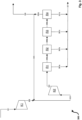
- figure 3 shows a highly simplified schematic block flow diagram of a production process according to the invention for methanol without a recycle gas compressor stage Synthesis loop, wherein the synthesis loop comprises a plurality of reactor stages arranged in series.
- a first fresh gas flow 301 with a pressure of 34.0 bar is fed to a first compressor stage K1.
- the fresh gas of the fresh gas stream 301 originates from a feed gas source which, with regard to carbon oxides, provides feed gas containing exclusively carbon dioxide. Due to the molar ratio of carbon dioxide to hydrogen of 3 to 1, a stoichiometry number SN of 2.0 results for the fresh gas of the fresh gas flow 301 .
- the first fresh gas stream 301 is compressed by the first compressor stage K1, so that a second fresh gas stream 302 with a pressure of 65.0 bar is obtained on the pressure side of the compressor stage K1.
- the second fresh gas stream 302 is combined with the recirculation gas stream 305, resulting in a combined gas stream 303, which is introduced into a second compressor stage K2 and is thereby compressed to a pressure of 85.0 bar.
- a gas stream with synthesis pressure results on the pressure side of the second compressor stage, which is referred to here as synthesis gas stream 304 .
- the synthesis gas stream 304 is introduced into a first of a total of four reactor stages R1 to R4 arranged in series.
- synthesis gas 304 is converted to methanol over a copper-based fixed bed catalyst with a catalyst volume of 4.2 m 3 .
- the reactor stages R2, R3 and R4 each have a catalyst volume of 4.2 m 3 of the same copper-based catalyst, resulting in a total catalyst volume of 16.8 m 3 , which corresponds to the catalyst volume of the individual reactor stage in the comparative examples figure 1 and figure 2 is equivalent to.
- reactor stage R1 Due to the incomplete conversion of the synthesis gas 304 in reactor stage R1, a stream of unreacted synthesis gas 306a is obtained, which is introduced into the following reactor stage arranged in series, here in reactor stage R2.
- reactor stage R1 and further reactor stages R2 to R4 also have a heat exchanger for cooling the product stream and a separator.
- a product stream 307a is obtained in R1 by cooling the product stream and condensing methanol in the separator.
- unreacted synthesis gas 306a is converted into methanol and by-products in reactor stage R2, as a result of which a further product stream 307b is obtained.
- Synthesis gas that has not reacted in the reaction on the copper-based catalyst of R2 is in turn fed into the following reactor stage R3, with a product stream 307c and unreacted synthesis gas 306c being obtained.
- a small proportion of unreacted synthesis gas R2 is always dissolved in the condensate (methanol) and is not available for the next reactor stage.
- Unreacted synthesis gas 306c is introduced into the last of the reactor stages R4 arranged in series, with a further product stream 307d being obtained.
- the product streams 307a to 307d are combined to form an overall product stream 307.
- Total product stream 307 has crude methanol which, depending on the required purity, is fed to a suitable work-up to obtain pure methanol (not shown).
- the pressure at the reactor outlet of reactor stage R4 is 74.9 bar.
- the pressure loss across all reactor stages is therefore 10.1 bar.
- Synthesis gas 306d that has not reacted in the last reactor stage is returned directly as recycle gas stream 305 to the second make-up gas stream 302 and combined with it.
- a portion of the unreacted synthesis gas drawn off in the last reactor stage R4 is used in accordance with the example figure 3 branched off as a purge gas stream in order to avoid the accumulation of inert components and by-products in the recycle gas stream 305 .
- the carbon dioxide conversion is in the example figure 3 98, 3 % and the hydrogen conversion is 98.6%.
- the conversions are thus consistent with the conversions according to the comparative examples (setup of the figures 1 and 2 ) comparable.
- the recirculation gas quantity 305 thus corresponds to 90% of the fresh gas quantity 302, in each case based on the standard volume flows of recirculation gas and fresh gas.
- the recirculation rate is therefore smaller by a factor of about 3.9 for the same carbon and hydrogen conversion than in the comparative examples, which is due to the higher conversion and the intermediate condensation of products in the majority of the reactor stages (R1 to R4).
- the feed gas contains only carbon dioxide with regard to carbon oxides.
- the volume flow of carbon dioxide is higher compared to the previous examples, as a result of which the fresh gas has an excess of carbon dioxide.
- the recirculation rate also surprisingly drops to 0.41, i.e. less than half of recycle gas 305 in relation to fresh gas 302 is required to produce the same amount of crude methanol 307 of 344 tons per day (of which 217.5 t/d methanol, the rest mainly water) with a high hydrogen conversion at the same time.
- the lower amount of recycle gas 305 also supplies a lower amount of purge gas required, which in turn means savings in hydrogen recovery.
- the hydrogen conversion is 98.8% and is therefore comparable to all previous examples.
- the carbon conversion is slightly lower at 89.5%, but this has no impact on the overall economy of the process given the low cost of this raw material, especially when it comes from off-gas sources.
Claims (15)
- Procédé de préparation de méthanol, comprenant les étapes de procédé suivantes :a) la fourniture d'un gaz d'alimentation comprenant des oxydes de carbone et de l'hydrogène (H2), la proportion de dioxyde de carbone (CO2) dans le gaz d'alimentation, par rapport à la quantité totale d'oxydes de carbone, étant d'au moins 80 % en volume ;b) l'introduction du gaz d'alimentation sous la forme d'un premier courant de gaz frais dans un premier étage de compresseur pour la pré-compression du premier courant de gaz frais, un deuxième courant de gaz frais étant obtenu ;c) l'introduction d'un courant de gaz de recyclage et du deuxième courant de gaz frais dans un deuxième étage de compresseur pour la compression du courant de gaz de recyclage et du deuxième courant de gaz frais à une pression de synthèse, un courant de gaz de synthèse étant obtenu ;d) la réaction catalytique du gaz de synthèse du courant de gaz de synthèse dans une pluralité d'étages de réacteur agencés en série à la pression de synthèse, un courant de produit comprenant du méthanol et du gaz de synthèse non réagi étant obtenu par étage de réacteur ;e) le refroidissement du courant de produit obtenu par étage de réacteur pour la condensation et la séparation de méthanol de gaz de synthèse non réagi et l'introduction de gaz de synthèse non réagi dans un étage respectif suivant des étages de réacteur agencés en série ;f) le soutirage de gaz de synthèse non réagi d'au moins l'un des étages de réacteur en tant que courant de gaz de recyclage pour l'introduction du courant de gaz de recyclage dans le deuxième étage de compresseur selon l'étape c).
- Procédé selon la revendication 1, caractérisé en ce que le courant de gaz de recyclage est introduit dans le deuxième étage de compresseur après le soutirage selon l'étape f) sans compression préalable.
- Procédé selon la revendication 1 ou 2, caractérisé en ce que, selon l'étape e), le gaz de synthèse non réagi est introduit en totalité dans l'étage respectif suivant des étages de réacteur agencés en série.
- Procédé selon l'une quelconque des revendications précédentes, caractérisé en ce que, selon l'étape f), le gaz de synthèse non réagi est soutiré du dernier de la pluralité d'étages de réacteur agencés en série en tant que courant de gaz de recyclage, notamment est soutiré exclusivement du dernier de la pluralité d'étages de réacteur agencés en série.
- Procédé selon l'une quelconque des revendications précédentes, caractérisé en ce que le courant de gaz de recyclage et le deuxième courant de gaz frais sont réunis et introduits dans le deuxième étage de compresseur sous forme de courant de gaz combiné.
- Procédé selon l'une quelconque des revendications précédentes, caractérisé en ce que le gaz d'alimentation présente un indice stœchiométrique SN, où

de 1,5 à 2,2. - Procédé selon la revendication 6, caractérisé en ce que le gaz d'alimentation présente un indice stœchiométrique SN de 1,5 à 1,9, de préférence de 1,6 à 1,8.
- Procédé selon l'une quelconque des revendications précédentes, caractérisé en ce que, pour un taux de recirculation R, défini comme


- Procédé selon la revendication 8, caractérisé en ce que, pour le taux de recirculation R : 0,1 ≤ R ≤ 0,5.
- Procédé selon l'une quelconque des revendications précédentes, caractérisé en ce qu'une conversion du dioxyde de carbone d'au moins 80 % en moles est obtenue par l'ensemble de la pluralité d'étages de réacteur agencés en série, à partir du gaz d'alimentation.
- Procédé selon l'une quelconque des revendications précédentes, caractérisé en ce que la pluralité d'étages de réacteur agencés en série comprend un nombre de 2 à 8 étages de réacteur.
- Installation pour la préparation de méthanol, comprenant les éléments d'installation suivants en communication fluidique les uns avec les autres :un premier étage de compresseur pour la pré-compression d'un premier gaz frais contenant des oxydes de carbone et de l'hydrogène (H2) pour la production d'un deuxième gaz frais ;un deuxième étage de compresseur, agencé en aval du premier étage de compresseur, pour la compression du deuxième gaz frais et d'un gaz de recyclage en un gaz de synthèse à une pression de synthèse ;une pluralité d'unités de réacteur agencées en série, agencée en aval du deuxième étage de compresseur pour la production d'un courant de produit de gaz de synthèse comprenant du méthanol et du gaz de synthèse non réagi, chacune des unités de réacteur comprenant :- un réacteur comprenant un lit de catalyseur,- un échangeur de chaleur pour le refroidissement du courant de produit, et- un séparateur pour la séparation de méthanol de gaz de synthèse non réagi,chacune des unités de réacteur comprenant une sortie pour le soutirage de méthanol, etchacune des unités de réacteur comprenant une sortie pour l'amenée de gaz de synthèse non réagi vers une unité de réacteur respective agencée ultérieurement, et/ou une sortie pour l'amenée de gaz de synthèse non réagi en tant que gaz de recyclage vers le deuxième étage de compresseur,une amenée pour l'introduction du gaz de recyclage dans le deuxième étage de compresseur étant agencée entre le premier et le deuxième étage de compresseur.
- Installation selon la revendication 12, caractérisée en ce qu'aucun étage de compresseur n'est agencé entre la sortie pour l'amenée de gaz de synthèse non réagi en tant que gaz de recyclage vers le deuxième étage de compresseur et l'amenée pour l'introduction du gaz de recyclage dans le deuxième étage de compresseur pour la compression préalable du gaz de recyclage avant l'introduction dans le deuxième étage de compresseur.
- Installation selon l'une quelconque des revendications 12 ou 13, caractérisée en ce qu'une sortie pour l'amenée de gaz de synthèse non réagi en tant que gaz de recyclage dans le deuxième étage de compresseur est agencée au niveau de la dernière de la pluralité d'unités de réacteur agencées en série, de préférence exclusivement au niveau de la dernière de la pluralité d'unités de réacteur agencées en série.
- Utilisation de l'installation selon l'une quelconque des revendications 12 à 14 dans un procédé selon l'une quelconque des revendications 1 à 11.
Priority Applications (3)
| Application Number | Priority Date | Filing Date | Title |
|---|---|---|---|
| EP19020480.0A EP3782974B1 (fr) | 2019-08-19 | 2019-08-19 | Procédé et installation de fabrication de méthanol à partir de gaz de synthèse à teneur augmentée en dioxyde de carbone |
| CN202010747689.XA CN112390703A (zh) | 2019-08-19 | 2020-07-28 | 用于从具有高比例的二氧化碳的合成气生产甲醇的方法和设备 |
| US16/996,185 US11078142B2 (en) | 2019-08-19 | 2020-08-18 | Process and plant for producing methanol from synthesis gases having a high proportion of carbon dioxide |
Applications Claiming Priority (1)
| Application Number | Priority Date | Filing Date | Title |
|---|---|---|---|
| EP19020480.0A EP3782974B1 (fr) | 2019-08-19 | 2019-08-19 | Procédé et installation de fabrication de méthanol à partir de gaz de synthèse à teneur augmentée en dioxyde de carbone |
Publications (2)
| Publication Number | Publication Date |
|---|---|
| EP3782974A1 EP3782974A1 (fr) | 2021-02-24 |
| EP3782974B1 true EP3782974B1 (fr) | 2023-03-01 |
Family
ID=67850932
Family Applications (1)
| Application Number | Title | Priority Date | Filing Date |
|---|---|---|---|
| EP19020480.0A Active EP3782974B1 (fr) | 2019-08-19 | 2019-08-19 | Procédé et installation de fabrication de méthanol à partir de gaz de synthèse à teneur augmentée en dioxyde de carbone |
Country Status (3)
| Country | Link |
|---|---|
| US (1) | US11078142B2 (fr) |
| EP (1) | EP3782974B1 (fr) |
| CN (1) | CN112390703A (fr) |
Families Citing this family (1)
| Publication number | Priority date | Publication date | Assignee | Title |
|---|---|---|---|---|
| EP3782973B1 (fr) * | 2019-08-19 | 2023-03-01 | L'air Liquide, Société Anonyme Pour L'Étude Et L'exploitation Des Procédés Georges Claude | Procédé et installation de fabrication de méthanol |
Family Cites Families (5)
| Publication number | Priority date | Publication date | Assignee | Title |
|---|---|---|---|---|
| EP2116295A1 (fr) | 2008-04-16 | 2009-11-11 | Methanol Casale S.A. | Procédé de production de méthanol à partir du reformage à la vapeur |
| WO2015193440A1 (fr) | 2014-06-20 | 2015-12-23 | Haldor Topsøe A/S | Réacteurs de méthanol en série |
| EP3205622B1 (fr) * | 2016-02-11 | 2018-05-09 | Ulrich Wagner | Procede de synthese de methanol |
| WO2017167642A1 (fr) | 2016-03-30 | 2017-10-05 | Haldor Topsøe A/S | Conception de processus de synthèse de méthanol pour grande capacité de production |
| EP3782973B1 (fr) * | 2019-08-19 | 2023-03-01 | L'air Liquide, Société Anonyme Pour L'Étude Et L'exploitation Des Procédés Georges Claude | Procédé et installation de fabrication de méthanol |
-
2019
- 2019-08-19 EP EP19020480.0A patent/EP3782974B1/fr active Active
-
2020
- 2020-07-28 CN CN202010747689.XA patent/CN112390703A/zh active Pending
- 2020-08-18 US US16/996,185 patent/US11078142B2/en active Active
Also Published As
| Publication number | Publication date |
|---|---|
| US11078142B2 (en) | 2021-08-03 |
| CN112390703A (zh) | 2021-02-23 |
| EP3782974A1 (fr) | 2021-02-24 |
| US20210053898A1 (en) | 2021-02-25 |
Similar Documents
| Publication | Publication Date | Title |
|---|---|---|
| EP2281793B1 (fr) | Procédé et installation destinés à la fabrication de méthanol | |
| EP3205622B1 (fr) | Procede de synthese de methanol | |
| EP3426601B1 (fr) | Procédé et installation pour la production d'un produit gazeux sous des conditions de charge variables | |
| EP3307675B1 (fr) | Procédé multipression pour la production d'ammoniac | |
| EP2181083A1 (fr) | Procédé et installation de production de méthanol | |
| DE10057863C2 (de) | Mehrdruckverfahren zur Herstellung von Ammoniak | |
| DE102004028200B3 (de) | Verfahren zur Durchführung heterogen katalytischer exothermer Gasphasenreaktionen für die Methanolsynthese | |
| DE102011017300A1 (de) | Verfahren und Anlage zur Herstellung vom Methanol aus inertenreichem Synthesegas | |
| EP2539307A1 (fr) | Procédé de production de méthanol | |
| EP3219697B1 (fr) | Synthese de methanol a partir de gaz de synthese ayant un manque d'hydrogene | |
| DE102016213668A1 (de) | Verfahren und Anlage zur Herstellung von Alkoholen oder Kohlenwasserstoffen | |
| EP3782974B1 (fr) | Procédé et installation de fabrication de méthanol à partir de gaz de synthèse à teneur augmentée en dioxyde de carbone | |
| EP3782973B1 (fr) | Procédé et installation de fabrication de méthanol | |
| EP1814823B1 (fr) | Procede de production d'uree a partir de gaz naturel | |
| EP3741738B1 (fr) | Procédé de fabrication de méthanol | |
| EP3020696B1 (fr) | Procede de fabrication d'un ou plusieurs produits de reaction | |
| EP3816145B1 (fr) | Procédé et système de fabrication de méthanol à partir de gaz de synthèse riche en hydrogène | |
| EP3969433A1 (fr) | Procédé et installation de synthèse de méthanol | |
| WO2017207110A1 (fr) | Procédé et installation de fabrication d'éthanol | |
| EP3744416B1 (fr) | Procédé et installation de synthèse de méthanol | |
| DE102015208128A1 (de) | Asymmetrische Kreislaufkaskaden in der Gaskatalyse | |
| EP4324815A1 (fr) | Procédé et installation de production de méthanol et de gaz de synthèse | |
| DE102016006709A1 (de) | Verfahren und Anlage zur Herstellung von Ethanol | |
| DE102022201172A1 (de) | Anlage zur Erzeugung von Ammoniak | |
| EP4286357A1 (fr) | Procédé et installation de production de méthanol |
Legal Events
| Date | Code | Title | Description |
|---|---|---|---|
| PUAI | Public reference made under article 153(3) epc to a published international application that has entered the european phase |
Free format text: ORIGINAL CODE: 0009012 |
|
| STAA | Information on the status of an ep patent application or granted ep patent |
Free format text: STATUS: THE APPLICATION HAS BEEN PUBLISHED |
|
| AK | Designated contracting states |
Kind code of ref document: A1 Designated state(s): AL AT BE BG CH CY CZ DE DK EE ES FI FR GB GR HR HU IE IS IT LI LT LU LV MC MK MT NL NO PL PT RO RS SE SI SK SM TR |
|
| AX | Request for extension of the european patent |
Extension state: BA ME |
|
| STAA | Information on the status of an ep patent application or granted ep patent |
Free format text: STATUS: REQUEST FOR EXAMINATION WAS MADE |
|
| 17P | Request for examination filed |
Effective date: 20210824 |
|
| RBV | Designated contracting states (corrected) |
Designated state(s): AL AT BE BG CH CY CZ DE DK EE ES FI FR GB GR HR HU IE IS IT LI LT LU LV MC MK MT NL NO PL PT RO RS SE SI SK SM TR |
|
| GRAP | Despatch of communication of intention to grant a patent |
Free format text: ORIGINAL CODE: EPIDOSNIGR1 |
|
| STAA | Information on the status of an ep patent application or granted ep patent |
Free format text: STATUS: GRANT OF PATENT IS INTENDED |
|
| RIC1 | Information provided on ipc code assigned before grant |
Ipc: C07C 31/04 20060101ALI20220901BHEP Ipc: C07C 29/151 20060101AFI20220901BHEP |
|
| INTG | Intention to grant announced |
Effective date: 20220921 |
|
| GRAS | Grant fee paid |
Free format text: ORIGINAL CODE: EPIDOSNIGR3 |
|
| GRAA | (expected) grant |
Free format text: ORIGINAL CODE: 0009210 |
|
| STAA | Information on the status of an ep patent application or granted ep patent |
Free format text: STATUS: THE PATENT HAS BEEN GRANTED |
|
| AK | Designated contracting states |
Kind code of ref document: B1 Designated state(s): AL AT BE BG CH CY CZ DE DK EE ES FI FR GB GR HR HU IE IS IT LI LT LU LV MC MK MT NL NO PL PT RO RS SE SI SK SM TR |
|
| REG | Reference to a national code |
Ref country code: GB Ref legal event code: FG4D Free format text: NOT ENGLISH |
|
| REG | Reference to a national code |
Ref country code: CH Ref legal event code: EP Ref country code: AT Ref legal event code: REF Ref document number: 1550881 Country of ref document: AT Kind code of ref document: T Effective date: 20230315 |
|
| REG | Reference to a national code |
Ref country code: DE Ref legal event code: R096 Ref document number: 502019007062 Country of ref document: DE |
|
| REG | Reference to a national code |
Ref country code: IE Ref legal event code: FG4D Free format text: LANGUAGE OF EP DOCUMENT: GERMAN |
|
| REG | Reference to a national code |
Ref country code: NO Ref legal event code: T2 Effective date: 20230301 |
|
| REG | Reference to a national code |
Ref country code: NL Ref legal event code: FP |
|
| REG | Reference to a national code |
Ref country code: LT Ref legal event code: MG9D |
|
| PG25 | Lapsed in a contracting state [announced via postgrant information from national office to epo] |
Ref country code: RS Free format text: LAPSE BECAUSE OF FAILURE TO SUBMIT A TRANSLATION OF THE DESCRIPTION OR TO PAY THE FEE WITHIN THE PRESCRIBED TIME-LIMIT Effective date: 20230301 Ref country code: LV Free format text: LAPSE BECAUSE OF FAILURE TO SUBMIT A TRANSLATION OF THE DESCRIPTION OR TO PAY THE FEE WITHIN THE PRESCRIBED TIME-LIMIT Effective date: 20230301 Ref country code: LT Free format text: LAPSE BECAUSE OF FAILURE TO SUBMIT A TRANSLATION OF THE DESCRIPTION OR TO PAY THE FEE WITHIN THE PRESCRIBED TIME-LIMIT Effective date: 20230301 Ref country code: HR Free format text: LAPSE BECAUSE OF FAILURE TO SUBMIT A TRANSLATION OF THE DESCRIPTION OR TO PAY THE FEE WITHIN THE PRESCRIBED TIME-LIMIT Effective date: 20230301 Ref country code: ES Free format text: LAPSE BECAUSE OF FAILURE TO SUBMIT A TRANSLATION OF THE DESCRIPTION OR TO PAY THE FEE WITHIN THE PRESCRIBED TIME-LIMIT Effective date: 20230301 |
|
| PG25 | Lapsed in a contracting state [announced via postgrant information from national office to epo] |
Ref country code: SE Free format text: LAPSE BECAUSE OF FAILURE TO SUBMIT A TRANSLATION OF THE DESCRIPTION OR TO PAY THE FEE WITHIN THE PRESCRIBED TIME-LIMIT Effective date: 20230301 Ref country code: PL Free format text: LAPSE BECAUSE OF FAILURE TO SUBMIT A TRANSLATION OF THE DESCRIPTION OR TO PAY THE FEE WITHIN THE PRESCRIBED TIME-LIMIT Effective date: 20230301 Ref country code: GR Free format text: LAPSE BECAUSE OF FAILURE TO SUBMIT A TRANSLATION OF THE DESCRIPTION OR TO PAY THE FEE WITHIN THE PRESCRIBED TIME-LIMIT Effective date: 20230602 Ref country code: FI Free format text: LAPSE BECAUSE OF FAILURE TO SUBMIT A TRANSLATION OF THE DESCRIPTION OR TO PAY THE FEE WITHIN THE PRESCRIBED TIME-LIMIT Effective date: 20230301 |
|
| PGFP | Annual fee paid to national office [announced via postgrant information from national office to epo] |
Ref country code: NL Payment date: 20230821 Year of fee payment: 5 |
|
| PG25 | Lapsed in a contracting state [announced via postgrant information from national office to epo] |
Ref country code: SM Free format text: LAPSE BECAUSE OF FAILURE TO SUBMIT A TRANSLATION OF THE DESCRIPTION OR TO PAY THE FEE WITHIN THE PRESCRIBED TIME-LIMIT Effective date: 20230301 Ref country code: RO Free format text: LAPSE BECAUSE OF FAILURE TO SUBMIT A TRANSLATION OF THE DESCRIPTION OR TO PAY THE FEE WITHIN THE PRESCRIBED TIME-LIMIT Effective date: 20230301 Ref country code: PT Free format text: LAPSE BECAUSE OF FAILURE TO SUBMIT A TRANSLATION OF THE DESCRIPTION OR TO PAY THE FEE WITHIN THE PRESCRIBED TIME-LIMIT Effective date: 20230703 Ref country code: EE Free format text: LAPSE BECAUSE OF FAILURE TO SUBMIT A TRANSLATION OF THE DESCRIPTION OR TO PAY THE FEE WITHIN THE PRESCRIBED TIME-LIMIT Effective date: 20230301 Ref country code: CZ Free format text: LAPSE BECAUSE OF FAILURE TO SUBMIT A TRANSLATION OF THE DESCRIPTION OR TO PAY THE FEE WITHIN THE PRESCRIBED TIME-LIMIT Effective date: 20230301 |
|
| PGFP | Annual fee paid to national office [announced via postgrant information from national office to epo] |
Ref country code: NO Payment date: 20230824 Year of fee payment: 5 |
|
| PG25 | Lapsed in a contracting state [announced via postgrant information from national office to epo] |
Ref country code: SK Free format text: LAPSE BECAUSE OF FAILURE TO SUBMIT A TRANSLATION OF THE DESCRIPTION OR TO PAY THE FEE WITHIN THE PRESCRIBED TIME-LIMIT Effective date: 20230301 Ref country code: IS Free format text: LAPSE BECAUSE OF FAILURE TO SUBMIT A TRANSLATION OF THE DESCRIPTION OR TO PAY THE FEE WITHIN THE PRESCRIBED TIME-LIMIT Effective date: 20230701 |
|
| PGFP | Annual fee paid to national office [announced via postgrant information from national office to epo] |
Ref country code: FR Payment date: 20230828 Year of fee payment: 5 Ref country code: DE Payment date: 20230821 Year of fee payment: 5 Ref country code: BE Payment date: 20230821 Year of fee payment: 5 |
|
| REG | Reference to a national code |
Ref country code: DE Ref legal event code: R097 Ref document number: 502019007062 Country of ref document: DE |
|
| PLBE | No opposition filed within time limit |
Free format text: ORIGINAL CODE: 0009261 |
|
| STAA | Information on the status of an ep patent application or granted ep patent |
Free format text: STATUS: NO OPPOSITION FILED WITHIN TIME LIMIT |
|
| PG25 | Lapsed in a contracting state [announced via postgrant information from national office to epo] |
Ref country code: SI Free format text: LAPSE BECAUSE OF FAILURE TO SUBMIT A TRANSLATION OF THE DESCRIPTION OR TO PAY THE FEE WITHIN THE PRESCRIBED TIME-LIMIT Effective date: 20230301 Ref country code: DK Free format text: LAPSE BECAUSE OF FAILURE TO SUBMIT A TRANSLATION OF THE DESCRIPTION OR TO PAY THE FEE WITHIN THE PRESCRIBED TIME-LIMIT Effective date: 20230301 |
|
| 26N | No opposition filed |
Effective date: 20231204 |
|
| PG25 | Lapsed in a contracting state [announced via postgrant information from national office to epo] |
Ref country code: MC Free format text: LAPSE BECAUSE OF FAILURE TO SUBMIT A TRANSLATION OF THE DESCRIPTION OR TO PAY THE FEE WITHIN THE PRESCRIBED TIME-LIMIT Effective date: 20230301 |
|
| REG | Reference to a national code |
Ref country code: CH Ref legal event code: PL |
|
| PG25 | Lapsed in a contracting state [announced via postgrant information from national office to epo] |
Ref country code: MC Free format text: LAPSE BECAUSE OF FAILURE TO SUBMIT A TRANSLATION OF THE DESCRIPTION OR TO PAY THE FEE WITHIN THE PRESCRIBED TIME-LIMIT Effective date: 20230301 |
|
| PG25 | Lapsed in a contracting state [announced via postgrant information from national office to epo] |
Ref country code: LU Free format text: LAPSE BECAUSE OF NON-PAYMENT OF DUE FEES Effective date: 20230819 |
|
| GBPC | Gb: european patent ceased through non-payment of renewal fee |
Effective date: 20230819 |
|
| PG25 | Lapsed in a contracting state [announced via postgrant information from national office to epo] |
Ref country code: LU Free format text: LAPSE BECAUSE OF NON-PAYMENT OF DUE FEES Effective date: 20230819 Ref country code: CH Free format text: LAPSE BECAUSE OF NON-PAYMENT OF DUE FEES Effective date: 20230831 |