EP3815648A1 - Intraocular ring insertion device with container - Google Patents
Intraocular ring insertion device with container Download PDFInfo
- Publication number
- EP3815648A1 EP3815648A1 EP19803973.7A EP19803973A EP3815648A1 EP 3815648 A1 EP3815648 A1 EP 3815648A1 EP 19803973 A EP19803973 A EP 19803973A EP 3815648 A1 EP3815648 A1 EP 3815648A1
- Authority
- EP
- European Patent Office
- Prior art keywords
- hollow body
- intraocular ring
- intraocular
- injector
- container
- Prior art date
- Legal status (The legal status is an assumption and is not a legal conclusion. Google has not performed a legal analysis and makes no representation as to the accuracy of the status listed.)
- Granted
Links
Images





Classifications
-
- A—HUMAN NECESSITIES
- A61—MEDICAL OR VETERINARY SCIENCE; HYGIENE
- A61F—FILTERS IMPLANTABLE INTO BLOOD VESSELS; PROSTHESES; DEVICES PROVIDING PATENCY TO, OR PREVENTING COLLAPSING OF, TUBULAR STRUCTURES OF THE BODY, e.g. STENTS; ORTHOPAEDIC, NURSING OR CONTRACEPTIVE DEVICES; FOMENTATION; TREATMENT OR PROTECTION OF EYES OR EARS; BANDAGES, DRESSINGS OR ABSORBENT PADS; FIRST-AID KITS
- A61F2/00—Filters implantable into blood vessels; Prostheses, i.e. artificial substitutes or replacements for parts of the body; Appliances for connecting them with the body; Devices providing patency to, or preventing collapsing of, tubular structures of the body, e.g. stents
- A61F2/02—Prostheses implantable into the body
- A61F2/14—Eye parts, e.g. lenses or corneal implants; Artificial eyes
- A61F2/16—Intraocular lenses
- A61F2/1694—Capsular bag spreaders therefor
-
- A—HUMAN NECESSITIES
- A61—MEDICAL OR VETERINARY SCIENCE; HYGIENE
- A61F—FILTERS IMPLANTABLE INTO BLOOD VESSELS; PROSTHESES; DEVICES PROVIDING PATENCY TO, OR PREVENTING COLLAPSING OF, TUBULAR STRUCTURES OF THE BODY, e.g. STENTS; ORTHOPAEDIC, NURSING OR CONTRACEPTIVE DEVICES; FOMENTATION; TREATMENT OR PROTECTION OF EYES OR EARS; BANDAGES, DRESSINGS OR ABSORBENT PADS; FIRST-AID KITS
- A61F2/00—Filters implantable into blood vessels; Prostheses, i.e. artificial substitutes or replacements for parts of the body; Appliances for connecting them with the body; Devices providing patency to, or preventing collapsing of, tubular structures of the body, e.g. stents
- A61F2/02—Prostheses implantable into the body
- A61F2/14—Eye parts, e.g. lenses or corneal implants; Artificial eyes
- A61F2/16—Intraocular lenses
- A61F2/1662—Instruments for inserting intraocular lenses into the eye
- A61F2/167—Instruments for inserting intraocular lenses into the eye with pushable plungers
-
- A—HUMAN NECESSITIES
- A61—MEDICAL OR VETERINARY SCIENCE; HYGIENE
- A61F—FILTERS IMPLANTABLE INTO BLOOD VESSELS; PROSTHESES; DEVICES PROVIDING PATENCY TO, OR PREVENTING COLLAPSING OF, TUBULAR STRUCTURES OF THE BODY, e.g. STENTS; ORTHOPAEDIC, NURSING OR CONTRACEPTIVE DEVICES; FOMENTATION; TREATMENT OR PROTECTION OF EYES OR EARS; BANDAGES, DRESSINGS OR ABSORBENT PADS; FIRST-AID KITS
- A61F2/00—Filters implantable into blood vessels; Prostheses, i.e. artificial substitutes or replacements for parts of the body; Appliances for connecting them with the body; Devices providing patency to, or preventing collapsing of, tubular structures of the body, e.g. stents
- A61F2/02—Prostheses implantable into the body
- A61F2/14—Eye parts, e.g. lenses or corneal implants; Artificial eyes
- A61F2/16—Intraocular lenses
- A61F2/1662—Instruments for inserting intraocular lenses into the eye
- A61F2/1678—Instruments for inserting intraocular lenses into the eye with a separate cartridge or other lens setting part for storage of a lens, e.g. preloadable for shipping
-
- A—HUMAN NECESSITIES
- A61—MEDICAL OR VETERINARY SCIENCE; HYGIENE
- A61F—FILTERS IMPLANTABLE INTO BLOOD VESSELS; PROSTHESES; DEVICES PROVIDING PATENCY TO, OR PREVENTING COLLAPSING OF, TUBULAR STRUCTURES OF THE BODY, e.g. STENTS; ORTHOPAEDIC, NURSING OR CONTRACEPTIVE DEVICES; FOMENTATION; TREATMENT OR PROTECTION OF EYES OR EARS; BANDAGES, DRESSINGS OR ABSORBENT PADS; FIRST-AID KITS
- A61F2/00—Filters implantable into blood vessels; Prostheses, i.e. artificial substitutes or replacements for parts of the body; Appliances for connecting them with the body; Devices providing patency to, or preventing collapsing of, tubular structures of the body, e.g. stents
- A61F2/02—Prostheses implantable into the body
- A61F2/14—Eye parts, e.g. lenses or corneal implants; Artificial eyes
- A61F2/16—Intraocular lenses
- A61F2/1691—Packages or dispensers for intraocular lenses
Definitions
- the present invention relates to an intraocular ring injector with a container.
- One of the treatment methods for cataract is a method using an intraocular lens.
- lens fibers nucleus, cortex
- an intraocular lens is injected into the lens capsule.
- a capsular tension ring may be sometimes placed as an intraocular ring into the lens capsule after the extracapsular cataract extraction, in order to retain the shape of the lens capsule.
- This intraocular ring is placed so as to be inscribed in the equatorial segment of the lens capsule, and retains the shape of the lens capsule by exerting an appropriate tension in this placement state (for example, FIG. 1 of Patent Document 1).
- FIG. 6 of Patent Document 1 shows hook 56 connected to piston 48 being hooked on opening 26 of the intraocular ring.
- Patent Document 1 Japanese Unexamined Patent Publication (Translation of PCT Application) No. 2003-527162
- a member that pushes out an intraocular ring in Patent Document 1, wire 54 having hook 56 is fitted into a hole (hereinafter referred to as an eyelet) of the intraocular ring.
- the plunger in Patent Document 1
- a nozzle which is a tip end of the intraocular ring injector, is then injected into a lens capsule through an incision in the patient's cornea. Subsequently, the intraocular ring is injected into the lens capsule through the nozzle.
- an operation of moving the plunger rearward must be performed while maintaining the engagement between the pushing member of the intraocular ring injector and the eyelet of the intraocular ring.
- the engagement may be released upon such an operation by the operator.
- a problem occurring in the intraocular ring while the operator is distracted by the movement of the plunger may be less likely to noticed by the operator.
- An object of the present invention is to provide an intraocular ring injector that allows an operator to stably and normally make an intraocular ring be housed into the intraocular ring injector.
- an operation to make the intraocular ring be housed in the intraocular ring injector is performed outside the container for housing the intraocular ring injector.
- the present inventor paid attention to this point and found that the above-mentioned housing operation is to be completed in the container.
- a first aspect of the present invention is an intraocular ring injector with a container configured so that the intraocular ring injector is housed in the container, for injecting an intraocular ring into an eye for retaining a shape of a lens capsule, the intraocular ring injector including:
- a second aspect of the present invention is the invention according to the first aspect, including a movement restricting portion that restricts a movement of the intraocular ring injector while being housed in the container, in a direction other than the axial direction.
- a third aspect of the present invention is the invention according to the second aspect, wherein the movement restricting portion cancels restriction of the movement of the intraocular ring injector, when the hollow body and the plunger are relatively moved by a distance for housing the intraocular ring in the hollow body, the intraocular ring being engaged with an axial end of the pushing member.
- a fourth aspect of the present invention is the invention according to the third aspect, wherein the distance is 20 to 50 mm.
- a fifth aspect of the present invention is the invention according to any one of the first to fourth aspects, wherein the container includes:
- a sixth aspect of the present invention is the invention according to the fifth aspect, wherein the hollow body movement restricting portion cancels the restriction of the movement of the hollow body, when the hollow body moves forward by the distance for housing the intraocular ring in the hollow body, the intraocular ring being engaged with an axial end of the pushing member.
- a seventh aspect of the present invention is the invention according to the fifth or sixth aspect, wherein a plurality of hollow body movement restricting portions are provided.
- An eighth aspect of the present invention is the invention according to any one of the fifth to seventh aspects, wherein the hollow body movement restricting portion is engaged with an outer circumference of the hollow body in the axial direction.
- a ninth aspect of the present invention is the invention according to any one of the fifth to eighth aspects, wherein the hollow body movement restricting portion further has a return restricting portion that restricts the hollow body from moving rearward in the axial direction.
- a tenth aspect of the present invention is the invention according to any one of the fifth to ninth aspects, wherein the plunger movement restricting portion is a groove that engages with a rear end of the plunger in the axial direction.
- An eleventh aspect of the present invention is the invention according to any one of the first to tenth aspects, wherein the hollow body has a nozzle for releasing the intraocular ring from an opening, and the nozzle has a shape in which one end is long and the other end is the same or short, and a short one end side of the opening of the nozzle is cut out, in a side view which is a direction perpendicular to the axial direction of the hollow body.
- a twelfth aspect of the present invention is the invention according to any one of the first to eleventh aspects, wherein the hollow body has the nozzle for releasing the intraocular ring from the opening, and an overhanging portion is provided to at least a part of the pushing member in the axial direction, for preventing backflow of an aqueous humor from the opening of the nozzle.
- a thirteenth aspect of the present invention is the invention according to any one of the first to twelfth aspects, wherein at least a front portion of the pushing member on which a protrusion is provided, is displaced from the axial direction of the plunger to a direction in which the protrusion is protruded.
- a fourteenth aspect of the present invention is the invention according to any one of the first to thirteenth aspects, further including an intraocular ring.
- Another aspect of the present invention is as follows.
- An injector for injecting an intraocular ring for retaining a shape of a lens capsule or an intraocular lens into an eye including a nozzle for releasing the intraocular ring or the intraocular lens, wherein the nozzle has a shape in which one end is long and the other end is the same or short, and the same or short end side of the opening of the nozzle is cut out, in a side view which is a direction perpendicular to the releasing direction.
- an additional cutout is provided rearward at the position closer to the short end relative to a midpoint between an upper long end and a lower short end of the nozzle.
- Still another aspect of the present invention is as follows.
- An intraocular ring injector for injecting an intraocular ring into an eye for retaining a shape of a lens capsule, the intraocular ring injector including:
- Still another aspect of the present invention is as follows.
- An intraocular ring injector for injecting an intraocular ring into an eye for retaining a shape of a lens capsule, the intraocular ring injector including:
- the intraocular ring can be stably and normally housed in the intraocular ring injector.
- FIG. 1 is an exploded schematic perspective view of intraocular ring injector with a container 20 of this embodiment.
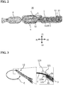
- FIG. 2 is a schematic perspective view of the intraocular ring injector with a container 20 of this embodiment.
- FIG. 3 is a schematic perspective view illustrating an intraocular ring C placed in the intraocular ring injector 10 of this embodiment.
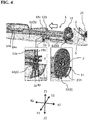
- FIG. 4 is a schematic perspective view of a part of the intraocular ring injector with a container 20 of this embodiment.
- one of the X axis directions is defined as X1 direction
- the other direction is defined as X2 direction
- one of the Y axis directions is defined as Y1 direction
- the other direction is defined as Y2 direction
- one of the Z axis directions is defined as Z1 direction and the other direction is defined as Z2 direction
- X1 direction is defined as a tip end side (forward)
- X2 direction is defined as a rear end side (rearward)
- Y1 direction is defined as a left side (leftward)
- Y2 direction is defined as a right side (rightward)
- Z1 direction is defined as an upper side (upward)
- Z2 direction is defined as a downside (downward).
- the X1 direction and X2 direction correspond to length directions of the intraocular ring injector 10
- the Y1 direction and Y2 direction correspond to width directions of the intraocular ring injector 10
- the Z1 direction and Z2 direction correspond to height directions of the intraocular ring injector 10.
- the main feature portion in this embodiment is the part involved in the engagement between the intraocular ring injector 10 and the container 4.
- a known configuration may be used except for the portion involved in the engagement. Therefore, the intraocular ring injector 10 itself and the container 4 itself will be hereinafter illustrated in a simplified manner.
- An intraocular ring C addressed in this embodiment includes a lens capsule tension ring (CTR) placed in an eye to retain the shape of a lens capsule.
- the CTR is formed in an open ring shape that is curved in an arc shape as a whole.
- An open ring shape means that a partially open ring.
- a known CTR can be used. For this reason, the description in its entirety relating to the CTR in Japanese Patent Laid-Open Publication No. 2016-214494 of the present applicant is considered to be indicated in this specification.
- this embodiment relates to intraocular ring injector with a container 20 configured so that intraocular ring injector 10 is housed in container 4, for injecting intraocular ring C into an eye for retaining a shape of a lens capsule.
- Intraocular ring injector 10 includes:
- the hollow body 1 is a main body of the intraocular ring injector 10.
- Nozzle 12 having opening 123 is disposed at a tip end of the hollow body 1.
- Flange 11 is provided at a rear end of the axial direction of the hollow body 1.
- the plunger 2 moves inside the hollow body 1 in the axial direction to push the intraocular ring C out of the nozzle 12 of the hollow body 1.
- the plunger 2 is disposed coaxially with the hollow body 1.
- the plunger 2 is provided movably in the axial direction of the hollow body 1.
- Pushing member 3 is formed in an elongated rod shape.
- the pushing member 3 is connected to the tip end part of the plunger 2 and moves integrally with the plunger 2 in the axial direction of the hollow body 1.
- the pushing member 3 may be integrally molded with the plunger 2.
- protrusion 31 for eyelet Ch is provided at the tip end part of pushing member 3 to face downward.
- the protrusion 31 is fitted into a hole (eyelet Ch) provided in the intraocular ring C. Since the eyelet Ch is fitted into the downward protrusion 31, when the protrusion 31 of the pushing member 3 goes out from the opening 123 of the nozzle 12, the protrusion 31 is quickly released from the engagement with the eyelet Ch so that the intraocular ring C is released into the lens capsule.
- the intraocular ring injector 10 of this embodiment may be a so-called preload type intraocular ring injector 10 in which the eyelet Ch of the intraocular ring C and the protrusion 31 of the pushing member 3 are engaged in advance.
- the eyelet Ch of the intraocular ring C and the protrusion 31 of the pushing member 3 may be engaged afterwards.
- the preload type does not require an engagement process by an operator, and therefore the intraocular ring C can be stably housed in the intraocular ring injector 10.
- the container 4 housing the intraocular ring injector 10 includes a moving mechanism of moving the hollow body 1 and the plunger 2 relatively in the axial direction, while housing the intraocular ring injector 10 in the container 4.
- This moving mechanism is not particularly limited so long as it can move the hollow body 1 and the plunger 2 relatively in the axial direction, while housing the intraocular ring injector 10 in the container 4.
- a sliding mechanism capable of sliding at least one of the hollow body 1 and the plunger 2 in the axial direction while housing the intraocular ring injector 10 in the container 4 may be used in at least one of the intraocular ring injector 10 and the container 4.
- the expression "move the hollow body 1 and the plunger 2 relatively in the axial direction” means that at least one of the hollow body 1 and the plunger 2 are moved in the axial direction so that the rear end of the hollow body 1 is distanced from the rear end of the plunger 2 (for example, the flange 11 of the hollow body 1 is distanced from the flange 21 of the plunger 2).
- the hollow body 1 and the plunger 2 it may be the hollow body 1, as mainly described in this embodiment, or the plunger 2, as described in the modified example, that is to be moved. Alternatively, the hollow body 1 and the plunger 2 may be moved together.
- Examples of the moving mechanism other than the above-described sliding mechanism include a movement restricting portion that restricts a movement of the intraocular ring injector 10 while being housed in the container 4, in a direction other than the axial direction.
- the phrase "restricts a movement of the intraocular ring injector 10 in a direction other than the axial direction" means that the intraocular ring injector 10 itself does not come out of the container 4. This state will be described.
- the movement restricting portion includes the plunger movement restricting portion 5 and the hollow body movement restricting portion 6.
- the plunger 2 is fit in a vertical groove, which is the plunger movement restricting portion 5, downward from above and fixed, as illustrated in FIG. 4 .
- the hollow body movement restricting portion 6 (protrusion 1p of the hollow body 1 and first protrusion 61 of the container, and cutout 11n of the flange of the hollow body and second protrusion 62 of the container) makes the hollow body 1 slide only in the axial direction.
- the plunger 2 may be movable upward when the flange 21 at the rear end of the plunger 2 is simply fit into the groove.
- the presence of the hollow body movement restricting portion 6 restricts the movement of the hollow body 1, and thus the intraocular ring injector 10 as a whole, in the direction other than the axial direction unless the hollow body 1 is moved forward by a predetermined distance.
- the movement of the intraocular ring injector in a direction other than the axial direction is restricted.
- the main examples of the container 4 of this embodiment are as follows.
- the container 4 housing the intraocular lens injector 10 includes:
- the plunger movement restricting portion 5 is not particularly limited so long as it can restrict a movement of the plunger 2 in the axial direction (forward and backward).
- the plunger movement restricting portion may be a groove that engages with the flange 21 at the rear end of the plunger 2. Such a groove may be provided at one position, or two positions of right and left sides. A groove that engages with the tip end part (rod-like portion), rather than the flange 21 at the rear end of the plunger 2 may be further provided.
- a ring-shaped member capable of completely fixing the plunger 2 may be used.
- the hollow body movement restricting portion 6 may be a member having a substantially C shape which can be held by fitting the hollow body 1 through the substantially C-shaped opening portion. It is preferably configured to be able to engage with the outer circumference of the hollow body 1 in the axial direction.
- a protrusion 1p extending in the axial direction, that is, in the forward and backward direction, of the hollow body 1 is provided on the outer circumference of the hollow body 1, and first protrusion 61 that engages with this protrusion 1p in the axial direction may be provided on the container 4.
- This configuration can restrict the hollow body 1 from moving in a direction other than the axial direction.
- the position where the hollow body movement restricting portion 6 is provided is not particularly limited as long as it is on the outer circumference of the hollow body 1.
- the protrusion 1p and the first protrusion 61 may be provided at positions corresponding to the outer circumference of the main body portion before the flange 11 of the hollow body 1.
- the hollow body movement restricting portion 6 may be provided with respect to the flange 11 of the hollow body 1.
- a cutout 11n may be provided on the lower portion of the flange 11 of the hollow body 1, the cutout being tapered (wider toward the center of the hollow body 1, and narrower toward the lower edge of the flange 11 of the hollow body 1) as viewed in the forward and backward direction.
- a second protrusion 62 having a shape corresponding to the tapered cutout 11n, that is, a shape having a wider upper portion and a narrower lower portion, and extending in the forward and backward direction, may be provided on the container 4.
- a plurality of hollow body movement restricting portions 6 may be provided.
- both of the protrusions 61 and 62 of the above two examples may be provided.
- FIG. 5(a) is a schematic plan view of the intraocular ring injector with a container 20 of this embodiment, with lid 8 of the container 4 closed, and FIG. 5(b) is a side view thereof.
- FIG. 6(a) is a schematic plan view of the intraocular ring injector with a container 20 of this embodiment, with lid 8 of the container 4 opened, and FIG. 6(b) is a side view thereof.
- the lid 8 of the container 4 of the intraocular ring injector 10 of this embodiment is opened. That is, a state as illustrated in FIG. 5 is changed to a state as illustrated in FIG. 6 .
- the lid 8 is provided so as to cover the tip end side of the hollow body 1, and a hinge is provided at the tip end of the container 4.
- an operator can notice an arrow provided on the bottom of the container 4. This arrow indicates the direction in which the hollow body 1 is to be moved.
- this embodiment is of a preload type, which does not require an operation to engage the protrusion 31 of the pushing member 3 with the eyelet Ch (opening) of the intraocular ring C. Even when it is not a preload type, such engagement can be made stably while the intraocular ring injector 10 is housed in the container 4. Moreover, since the hook 9 is provided for hooking the intraocular ring C, such engagement can be made more stably. The rest of the intraocular ring C, excluding the vicinity of the eyelet Ch, is then disposed outside of the nozzle 12.
- FIG. 7 is a schematic perspective view of the intraocular ring injector with a container 20 of this embodiment (a part of the hollow body 1 where the intraocular ring C and the pushing member 3 are present is illustrated as a transparent view), after moving the hollow body 1.
- the hollow body movement restricting portion 6 the hollow body 1 can be moved forward without the hollow body 1 being disengaged from the container 4.
- the intraocular ring C which has been protruding out of the nozzle 12, can be stably and normally housed inside the hollow body 1 as illustrated in FIG. 7 .
- such housing can be done while the intraocular ring injector 10 is housed in container 4.
- the operator may remove the hollow body 1 from the approximately C-shaped member to cancel the restrictions on the movement of the hollow body 1 by the hollow body movement restricting portion 6.
- the hollow body movement restricting portion 6 may be eliminated, when the hollow body 1 moves a distance such that the rest of the intraocular ring C excluding the vicinity of the eyelet Ch is housed in the hollow body 1.
- the length in the forward and backward direction of the protrusion 1p provided on the outer circumference of the hollow body 1 and the length in the forward and backward direction of the protrusions 61 and 62 provided in the container 4 are set to the value equal to or close to that distance.
- the length of the protrusions 61 and 62 provided in the container 4 is set to the value equal to or close to that distance.
- the above-described distance may be set to, for example, 20 to 50 mm (preferably 25 to 45 mm) in consideration of the circumference of the known intraocular ring C.
- the hollow body movement restricting portion 6 cancels the restriction on the movement of the hollow body 1. Then, the intraocular ring injector 10 can be taken out from the container 4 with the intraocular ring injector 10 facing upward (white arrow in FIG. 7 ).
- the intraocular ring injector 10 can be easily taken out from the container 4 with the intraocular ring injector facing upward (white arrow in FIG. 7 ).
- the intraocular ring injector 10 can be taken out from the container 4 with the intraocular ring injector facing upwards by separately releasing the fixation.
- the plunger movement restricting portion 5 that is a groove is more preferable because it does not require such a fixation-releasing operation.
- the hollow body movement restricting portion 6 further has a return restricting portion 7 that restricts the hollow body 1 from moving rearward in the axial direction.
- a leaf spring is provided on the left side or on the right side of the hollow body movement restricting portion 6 for the flange 21 of the plunger 2, the leaf spring having a length in an axial direction equivalent to the length of the second protrusion 62.
- This leaf spring is tapered so that the width in the vertical direction increases toward the front, for example.
- the return restricting portion 7 having a configuration other than those described above may be adopted.
- FIG. 8(a) is a schematic side view of an example of this embodiment in which a return restricting portion 7 is distinct from a stopper 4s
- FIG. 8(b) is a schematic side view of an example of modified embodiment in which a return restricting portion 7 is integrated with a stopper 4s.
- the return restricting portion 7 and the stopper 4s may be integrated.
- the portion connecting the return restricting portion 7 to the stopper 4s forms groove 71. Therefore, as the hollow body 1 moves forward, the resistance increases.
- the cutout 11n of the flange 11 of the hollow body 1 engages with the groove 71, thereby fixing the hollow body 1 and restricting the hollow body 1 from returning rearward.
- one or more protrusions may be provided on the second protrusion 62, so that resistance is created when moving the hollow body 1 (and thus the flange 11 of the hollow body 1).
- This configuration can restrict the hollow body 1 from moving backward even when an unintended force is applied to the hollow body 1 that causes the hollow body 1 to move rearward.
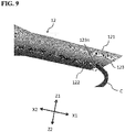
- FIG. 9 is a schematic side view of the nozzle 12 of the intraocular ring injector 10 of this embodiment.
- the shape of the nozzle 12 when viewed from the right-left direction is as follows.
- the nozzle 12 may have a shape in which the upper part of the nozzle 12 has a long end 121 and the lower part of the nozzle 12 has the same or short end 122, and further the nozzle 12 may have a shape in which the same or short end 122 side of the opening 123 of the nozzle 12 is cut out (numeral reference, 123n).
- the release direction of the intraocular ring C can be controlled.
- the intraocular ring C is first exposed to the outside of the opening 123 at the cutout portion 123n of the opening 123 of the nozzle 12. Since the intraocular ring C is curved, the intraocular ring C is easily discharged to the outside of the opening 123 while contacting the cutout portion 123n, as illustrated in FIG. 9 .
- the portion of the opening 123 pointed by the arrow 123n in FIG. 9 may be further cut out rearward. That is, an additional cutout may be provided rearward with respect to the cutout indicated by the broken line.
- the position of the additional cutout is preferably closer to the short end 122, compared to the midpoint between the upper long end 121 and the lower short end 122 of the nozzle 12.
- the additional cutout can increase the area of the intraocular ring C contacting the opening during release of the intraocular ring C.
- the intraocular ring C is easily released while the intraocular ring C is fitted in the cutout portion 123n. It means that the direction to which the intraocular ring C is released tends to be constant. Moreover, such tendency becomes remarkable by cutting out the short end 122 side of the opening 123 of the nozzle 12 when the nozzle 12 has a tapered shape in which the upper part of the nozzle 12 is long and the lower part is short.
- FIG. 10 is a schematic perspective view illustrating overhanging portion 32 provided in the pushing member 3 of the intraocular ring injector 10 of this embodiment. Note that the nozzle 12 is illustrated as transparent.
- This configuration can prevent the aqueous humor in the eye from flowing back into the nozzle 12 during the surgical procedure. The circumstances leading to the provision of this configuration will be hereinafter explained.
- the intraocular ring injector 10 in which the intraocular ring C is housed in the nozzle 12, the intraocular ring C is not folded, unlike the intraocular lens.
- the intraocular lens In the case of an intraocular "lens" injector, the intraocular lens is folded compactly and compressed, when it passes through the nozzle. Accordingly, there is almost no space through which the aqueous humor can flow back from the nozzle of the intraocular "lens” injector, so that the aqueous humor does not flow back.
- a gap (clearance) between a pushing member and an inner wall of a nozzle. That is, the present inventor has focused on the fact that the aqueous humor may possibly flow back into the nozzle during the surgical procedure in the conventional case. As a result, with the intention of preventing the backflow of the aqueous humor, the present inventor has devised a configuration in which at least a part of the pushing member 3 in the axial direction is provided with a flange, that is, overhanging portion 32, which overhangs in a direction perpendicular to the axial direction.
- Examples of such a configuration include a configuration in which overhanging portion 32 for preventing backflow of the aqueous humor from the opening 123 of the nozzle 12 is provided only for a part of the pushing member 3 in the axial direction.
- Examples of such overhanging portion 32 include a flange which enables the pushing member 3 to have a diameter equal to the inner diameter of the nozzle 12. In other words, there may be a gap formed between the inner wall of the nozzle 12 and a portion in the axial direction other than the overhanging portion 32 of the pushing member 3, as in the conventional case. The gap is filled with the overhanging portion 32.
- the overhanging portion 32 may be provided so that the pushing member 3 corresponds to the inner diameter of the nozzle 12. On the other hand, there may be a small gap between the pushing member and the inner wall of the nozzle 12, provided that backflow of the aqueous humor can be prevented.
- the overhanging portion 32 may be provided on all the portions in the axial direction other than a part provided with the protrusion 31. However, as illustrated in FIG. 10 , it may be provided on some of the portions, so as to reduce the weight of the pushing member 3, and thus the weight of the whole intraocular ring injector 10.
- a set of two plate-shaped protrusions 13a and 13b may be provided between the flange 11 on the outer circumference of the hollow body and the nozzle 12 in each of the right-left and up-down directions.
- the plate-shaped protrusions 13a and 13b may be configured to become wider from the tip end toward the rear end. This makes it easier for the operator to grip the hollow body 1.
- the long end of the nozzle 12 When viewed from the back to the front, the long end of the nozzle 12 is disposed at the position sandwiched between the upper set of two plate-shaped protrusions 13a and 13b.
- the opening 123 of the nozzle 12 is oriented forward and downward, and placed at the position between a lower set of two plate-shaped protrusions 13a and 13b.
- the operator can grasp the approximate position of the opening 123 of the nozzle 12 by reference to the upper set of two plate-shaped protrusions 13a and 13b.
- another set of two plate-shaped protrusions 14a and 14b may be provided at the position sandwiched between the upper set of two plate-shaped protrusions 13a and 13b, and between the nozzle 12 and the plate-shaped protrusions 13a and 13b.
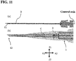
- FIG. 11(a) is a schematic side view illustrating a pushing member of a conventional intraocular ring injector
- FIG. 11(b) is a schematic side view illustrating the vicinity of a nozzle of the conventional intraocular ring injector. Note that the nozzle is illustrated as transparent.
- FIG. 12(a) is a schematic side view illustrating a pushing member 3 of the intraocular ring injector 10 of this embodiment
- FIG. 12(b) is a schematic side view illustrating the vicinity of a nozzle 12 of the intraocular ring injector 10 of this embodiment. Note that the nozzle 12 is illustrated as transparent.
- the tip end part of the pushing member 3 of the intraocular ring injector 10 As illustrated in FIG. 12 , it is preferred to displace downward at least the tip end (front) part of the pushing member 3 of the intraocular ring injector 10 on the inner circumference of the nozzle 12, the tip end part having a protrusion 31 provided thereon. Focusing on the pushing member 3 alone, it is preferable to displace at least the above-described tip end part from the axial direction of the plunger 2 to the direction in which the protrusion 31 is protruded. This configuration can prevent the intraocular ring C from falling out of the protrusion 31 when pulling the intraocular ring C into the nozzle 12 and, in turn, making the intraocular ring C be housed in the hollow body 1. The circumstances leading to the provision of this configuration will be hereinafter explained.
- the inner circumference of the nozzle 12 in this embodiment has a tapered shape with the thinner tip end side and the thicker rear end side.
- this nozzle 12 is basically adopted, and the pushing member 3 and the plunger 2 are coaxially designed as illustrated in FIG. 11(a) .
- the more the intraocular ring C is pulled into the nozzle 12 and thus more into the hollow body 1 hereinafter, description will be made for the nozzle 12
- the larger the clearance black arrow in FIG. 11(b)
- the intraocular ring C may be possibly disengaged from the protrusion 31 of the tip end part of the pushing member 3.
- the tip end part of the pushing member 3 is designed to be located below the central axis of the plunger 2 (circled in FIG. 12(a) ).
- the clearance between the protrusion 31 of the tip end part of the pushing member 3 and the inner circumference of the nozzle 12 can be reduced (circled in FIG. 12(b) ), the intraocular ring C being pulled into the inside of the nozzle 12.
- the intraocular ring C can be prevented from being disengaged from the protrusion 31 of the tip end part of the pushing member 3.
- the entire pushing member 3 attached to the plunger 2 or the entire rod-shaped part on the tip end side from the part engaged with the plunger 2 is tilted from the axial direction of the plunger 2 to the direction in which the protrusion 31 is protruded.
- the tip end part of the pushing member 3 of the intraocular ring injector 10 can be displaced downward on the inner circumference of the nozzle 12, the tip end part having the protrusion 31 provided thereon.
- the protrusion 31 may be displaced to the extent that it contacts the inner circumference of the nozzle 12.
- the protrusion 31 may be displaced to the extent that it contacts the circumference of the nozzle 12 until it reaches the position where the intraocular ring C is pulled into the inside of the nozzle 12.
- the pushing member 3 may be displaced in the direction in which the protrusion 31 is protruded, the pushing member 3 may extend as it is, and the tip end part provided with the protrusion 31 may be displaced downward on the inner circumference of the nozzle 12.
- only the tip end part of the pushing member 3 may be displaced downward on the inner circumference of the nozzle 12, the tip end part having the protrusion 31 provided thereon.
- Each of the above configurations makes it possible to move forward the hollow body 1, which is a main body of the intraocular ring injector 10, while restricting the movement of the plunger 2 in the forward and backward direction in the state where the intraocular ring injector 10 is housed in the container 4. Thereby, the operation of making the intraocular ring C be housed in the intraocular ring injector 10 can be completed in the container 4.
- the intraocular ring C can be stably housed in the hollow body 1 while stably maintaining the engagement between the pushing member 3 of the intraocular ring injector 10 and the eyelet Ch of the intraocular ring C.
- the operator can normally make the intraocular ring C be housed in the hollow body 1 while being conscious of the intraocular ring C and not being distracted by the movement of the plunger 2 as in the conventional case.
- the operator can make the intraocular ring C be stably and normally housed in the intraocular ring injector 10.
- the intraocular ring injector 10 of this embodiment may be, for example, a disposable type made of resin, or it may be a repeatedly usable type.
- the disposable type is preferable because it does not need to be cleaned and disinfected each time, which saves time and labor.
- This embodiment has been illustrated mainly referring to an example in which the movement of the plunger 2 in the axial direction is mainly restricted, while the hollow body 1 is allowed to move only in the axial direction.
- the above relationship may be reversed.
- the movement of the hollow body 1 in the axial direction is restricted, while the movement of plunger 2 is allowed only in the axial direction.
- the "moving mechanism of moving the hollow body 1 and the plunger 2 relatively in the axial direction, while housing the intraocular ring injector 10 in the container 4" described previously in this embodiment includes this configuration.
- a sliding mechanism capable of sliding at least one of the hollow body 1 and the plunger 2 in the axial direction while housing the intraocular ring injector 10 in the container 4.
- a movement restricting portion that restricts the movement of the intraocular ring injector 10 while being housed in the container 4 in a direction other than the axial direction.
- the movement restricting portion cancels restriction on the movement of the intraocular ring injector 10, when the hollow body 1 and the plunger 2 are relatively moved, that is, the hollow body 1 is fixed and then the plunger 2 is moved by a distance for housing the intraocular ring C in the hollow body 1, the intraocular ring being engaged with an axial end of the pushing member.
- a vertical groove into which the flange 11 of the hollow body 1 can be fitted downward from above may be provided in the container 4.
- an engagement mechanism similar to the protrusion 1p of the hollow body 1 and the first protrusion 61 of the container may be provided in the rod-shaped portion of the plunger 2 and in the container 4.
- an engagement mechanism similar to the cutout 11n of the flange 11 of the hollow body 1 and the second protrusion 62 of the container may be provided for the flange 21 of the plunger 2.
- the hollow body 1 and the plunger 2 may be moved together.
- an engagement mechanism similar to the protrusion 1p of the hollow body 1 and the first protrusion 61 of the container, or an engagement mechanism similar to the cutout 11n of the flange 11 of the hollow body 1 and the second protrusion 62 of the container may be provided for the plunger 2, the hollow body 1, and the container 4.
- the moving distance is preferably 20 to 50 mm (preferably 25 to 45 mm), as in this embodiment.
- the lens capsule tension ring (CTR) is exemplified as the intraocular ring C.
- the technical idea of the present invention can also be applied to the intraocular ring injector 10 which utilizes the intracorneal ring as the intraocular ring C.
- the above embodiment in which the nozzle 12 is cut out can be an invention by itself, by setting the release direction of the intraocular ring C tending to be constant as the problem and effect of the invention. Moreover, the problem and effect can be applied not only to the intraocular ring C but also to the intraocular lens.
- one configuration of the present invention is as follows.
- An injector for injecting an intraocular ring C for retaining a shape of a lens capsule, or an intraocular lens into an eye including nozzle 12 for releasing the intraocular ring C or intraocular lens, wherein the nozzle 12 has a shape in which one end 121 is long and the other end 122 is the same or short, and the same or short one end 122 side of the opening 123 of the nozzle 12 is cut out, in a side view which is a direction perpendicular to the releasing direction.
- an additional cutout is provided rearward at the position closer to the short end 122 relative to a midpoint between an upper long end 121 and a lower short end 122 of the nozzle 12.
- the overhanging portion 32 provided in the pushing member 3 described above can be an invention by itself, by setting the prevention of the backflow of the aqueous humor as the problem and effect.
- one configuration of the present invention is as follows.
- An intraocular ring injector 10 for injecting an intraocular ring C into an eye for retaining a shape of a lens capsule including:
- the above-described displacement of the pushing member 3 can be an invention by itself, by setting the intraocular ring C being possibly disengaged from the protrusion 31 of the tip end part of the pushing member 3 while pulling the intraocular ring C into the inside of the nozzle 12, as a problem and to solve the above problem is envisaged as an effect.
- one configuration of the present invention is as follows.
- An intraocular ring injector 10 for injecting an intraocular ring C into an eye for retaining a shape of a lens capsule including:
Landscapes
- Health & Medical Sciences (AREA)
- Ophthalmology & Optometry (AREA)
- Cardiology (AREA)
- Oral & Maxillofacial Surgery (AREA)
- Transplantation (AREA)
- Engineering & Computer Science (AREA)
- Biomedical Technology (AREA)
- Heart & Thoracic Surgery (AREA)
- Vascular Medicine (AREA)
- Life Sciences & Earth Sciences (AREA)
- Animal Behavior & Ethology (AREA)
- General Health & Medical Sciences (AREA)
- Public Health (AREA)
- Veterinary Medicine (AREA)
- Prostheses (AREA)
Abstract
Description
- The present invention relates to an intraocular ring injector with a container.
- One of the treatment methods for cataract is a method using an intraocular lens. In this treatment method, lens fibers (nucleus, cortex) are removed from a lens capsule by extracapsular cataract extraction, and then an intraocular lens is injected into the lens capsule. In that case, prior to the injection of the intraocular lens, a capsular tension ring (CTR) may be sometimes placed as an intraocular ring into the lens capsule after the extracapsular cataract extraction, in order to retain the shape of the lens capsule. This intraocular ring is placed so as to be inscribed in the equatorial segment of the lens capsule, and retains the shape of the lens capsule by exerting an appropriate tension in this placement state (for example,
FIG. 1 of Patent Document 1). - Various intraocular ring injectors have been developed for injecting such an intraocular ring into a lens capsule (for example, "ring introducer" in Patent Document 1).
FIG. 6 ofPatent Document 1 shows hook 56 connected to piston 48 being hooked on opening 26 of the intraocular ring. A surgeon as an operator needs only to manipulate a ring injector, which enables removal of an end part of the lens capsule ring which is an intraocular ring out of the cannula and expulsion of the lens capsule ring through the ring injector ([0028] of Patent Document 1). - [Patent Document 1] Japanese Unexamined Patent Publication (Translation of PCT Application) No.
2003-527162 - In a conventional intraocular ring injector, a member that pushes out an intraocular ring (in
Patent Document 1, wire 54 having hook 56) is fitted into a hole (hereinafter referred to as an eyelet) of the intraocular ring. After that, the plunger (piston 72 in Patent Document 1) is moved rearward. As a result, the intraocular ring is housed in the intraocular ring injector. A nozzle, which is a tip end of the intraocular ring injector, is then injected into a lens capsule through an incision in the patient's cornea. Subsequently, the intraocular ring is injected into the lens capsule through the nozzle. - Among the above operations, an operation of moving the plunger rearward must be performed while maintaining the engagement between the pushing member of the intraocular ring injector and the eyelet of the intraocular ring. The engagement may be released upon such an operation by the operator. Besides, a problem occurring in the intraocular ring while the operator is distracted by the movement of the plunger may be less likely to noticed by the operator.
- An object of the present invention is to provide an intraocular ring injector that allows an operator to stably and normally make an intraocular ring be housed into the intraocular ring injector.
- With the conventional intraocular ring injector, an operation to make the intraocular ring be housed in the intraocular ring injector is performed outside the container for housing the intraocular ring injector. The present inventor paid attention to this point and found that the above-mentioned housing operation is to be completed in the container.
- The configurations obtained based on the above findings are as follows.
- A first aspect of the present invention is an intraocular ring injector with a container configured so that the intraocular ring injector is housed in the container, for injecting an intraocular ring into an eye for retaining a shape of a lens capsule,
the intraocular ring injector including: - a hollow body having a hollow part in which the intraocular ring is housed;
- a plunger that moves through an inside of the hollow body in an axial direction of the hollow body; and
- a pushing member that pushes out the intraocular ring by moving together with the plunger through the inside of the hollow body and toward front part of the hollow body in the axial direction,
- A second aspect of the present invention is the invention according to the first aspect, including a movement restricting portion that restricts a movement of the intraocular ring injector while being housed in the container, in a direction other than the axial direction.
- A third aspect of the present invention is the invention according to the second aspect, wherein the movement restricting portion cancels restriction of the movement of the intraocular ring injector, when the hollow body and the plunger are relatively moved by a distance for housing the intraocular ring in the hollow body, the intraocular ring being engaged with an axial end of the pushing member.
- A fourth aspect of the present invention is the invention according to the third aspect, wherein the distance is 20 to 50 mm.
- A fifth aspect of the present invention is the invention according to any one of the first to fourth aspects, wherein the container includes:
- a plunger movement restricting portion that restricts a movement of the plunger in the axial direction, while housing the intraocular ring injector in the container; and
- a hollow body movement restricting portion that restricts the movement of the hollow body in a direction other than the axial direction, while permitting the movement of the hollow body in the axial direction, while housing the intraocular ring injector in the container.
- A sixth aspect of the present invention is the invention according to the fifth aspect, wherein the hollow body movement restricting portion cancels the restriction of the movement of the hollow body, when the hollow body moves forward by the distance for housing the intraocular ring in the hollow body, the intraocular ring being engaged with an axial end of the pushing member.
- A seventh aspect of the present invention is the invention according to the fifth or sixth aspect, wherein a plurality of hollow body movement restricting portions are provided.
- An eighth aspect of the present invention is the invention according to any one of the fifth to seventh aspects, wherein the hollow body movement restricting portion is engaged with an outer circumference of the hollow body in the axial direction.
- A ninth aspect of the present invention is the invention according to any one of the fifth to eighth aspects, wherein the hollow body movement restricting portion further has a return restricting portion that restricts the hollow body from moving rearward in the axial direction.
- A tenth aspect of the present invention is the invention according to any one of the fifth to ninth aspects, wherein the plunger movement restricting portion is a groove that engages with a rear end of the plunger in the axial direction.
- An eleventh aspect of the present invention is the invention according to any one of the first to tenth aspects, wherein the hollow body has a nozzle for releasing the intraocular ring from an opening, and the nozzle has a shape in which one end is long and the other end is the same or short, and a short one end side of the opening of the nozzle is cut out, in a side view which is a direction perpendicular to the axial direction of the hollow body.
- A twelfth aspect of the present invention is the invention according to any one of the first to eleventh aspects, wherein the hollow body has the nozzle for releasing the intraocular ring from the opening, and an overhanging portion is provided to at least a part of the pushing member in the axial direction, for preventing backflow of an aqueous humor from the opening of the nozzle.
- A thirteenth aspect of the present invention is the invention according to any one of the first to twelfth aspects, wherein at least a front portion of the pushing member on which a protrusion is provided, is displaced from the axial direction of the plunger to a direction in which the protrusion is protruded.
- A fourteenth aspect of the present invention is the invention according to any one of the first to thirteenth aspects, further including an intraocular ring.
- Another aspect of the present invention is as follows.
- An injector for injecting an intraocular ring for retaining a shape of a lens capsule or an intraocular lens into an eye, including a nozzle for releasing the intraocular ring or the intraocular lens, wherein the nozzle has a shape in which one end is long and the other end is the same or short, and the same or short end side of the opening of the nozzle is cut out, in a side view which is a direction perpendicular to the releasing direction.
- Preferably, with respect to a cutout on the same or short end side, an additional cutout is provided rearward at the position closer to the short end relative to a midpoint between an upper long end and a lower short end of the nozzle.
- Still another aspect of the present invention is as follows.
- An intraocular ring injector for injecting an intraocular ring into an eye for retaining a shape of a lens capsule,
the intraocular ring injector including: - a hollow body having a hollow part in which the intraocular ring is housed;
- a plunger that moves through an inside of the hollow body in an axial direction of the hollow body; and
- a pushing member that pushes out the intraocular ring by moving together with the plunger through the inside of the hollow body and toward front part of the hollow body in the axial direction,
- wherein the hollow body has the nozzle for releasing the intraocular ring from the opening, and an overhanging portion is provided to at least a part of the pushing member in the axial direction, for preventing backflow of an aqueous humor from the opening of the nozzle.
- Still another aspect of the present invention is as follows.
- An intraocular ring injector for injecting an intraocular ring into an eye for retaining a shape of a lens capsule,
the intraocular ring injector including: - a hollow body having a hollow part in which the intraocular ring is housed;
- a plunger that moves through an inside of the hollow body in an axial direction of the hollow body; and
- a pushing member that pushes out the intraocular ring by moving together with the plunger through the inside of the hollow body and toward front part of the hollow body in the axial direction,
- According to the present invention, the intraocular ring can be stably and normally housed in the intraocular ring injector.
-
-
FIG. 1 is an exploded schematic perspective view of an intraocular ring injector with a container of this embodiment. -
FIG. 2 is a schematic perspective view of the intraocular ring injector with a container of this embodiment. -
FIG. 3 is a schematic perspective view illustrating an intraocular ring placed in the intraocular ring injector of this embodiment. -
FIG. 4 is a schematic perspective view of a part of the intraocular ring injector with a container of this embodiment, before moving the hollow body. -
FIG. 5(a) is a schematic plan view of the intraocular ring injector with a container of this embodiment, with a lid of the container closed, andFIG. 5(b) is a side view thereof. -
FIG. 6(a) is a schematic plan view of the intraocular ring injector with a container of this embodiment, with a lid of the container opened, andFIG. 6(b) is a side view thereof. -
FIG. 7 is a schematic perspective view of the intraocular ring injector with a container of this embodiment (a part of the hollow body where the intraocular ring and the pushing member are present is illustrated as a transparent view), after moving the hollow body. -
FIG. 8(a) is a schematic side view of an example of this embodiment in which a return restricting portion is distinct from a stopper, andFIG. 8(b) is a schematic side view of an example of modified embodiment in which a return restricting portion is integrated with a stopper. -
FIG. 9 is a schematic side view of the nozzle of the intraocular ring injector of this embodiment. -
FIG. 10 is a schematic perspective view illustrating an overhanging portion provided in the pushing member of the intraocular ring injector of this embodiment. -
FIG. 11(a) is a schematic side view illustrating a pushing member of a conventional intraocular ring injector, andFIG. 11(b) is a schematic side view illustrating the vicinity of a nozzle of the conventional intraocular ring injector. -
FIG. 12(a) is a schematic side view illustrating a pushing member of the intraocular ring injector of this embodiment, andFIG. 12(b) is a schematic side view illustrating the vicinity of a nozzle of the intraocular ring injector of this embodiment. - Embodiments of the present invention will be described hereafter, with reference to the drawings. In the present specification, "to" refers to a predetermined value or more and a predetermined value or less.
-
FIG. 1 is an exploded schematic perspective view of intraocular ring injector with acontainer 20 of this embodiment. -
FIG. 2 is a schematic perspective view of the intraocular ring injector with acontainer 20 of this embodiment. -
FIG. 3 is a schematic perspective view illustrating an intraocular ring C placed in theintraocular ring injector 10 of this embodiment. -
FIG. 4 is a schematic perspective view of a part of the intraocular ring injector with acontainer 20 of this embodiment. - Further, in this embodiment, in describing a relative positional relationship and a direction of movement and the like of each part of the
intraocular ring injector 10, one of the X axis directions is defined as X1 direction, the other direction is defined as X2 direction, and one of the Y axis directions is defined as Y1 direction, the other direction is defined as Y2 direction, and one of the Z axis directions is defined as Z1 direction and the other direction is defined as Z2 direction, and X1 direction is defined as a tip end side (forward), X2 direction is defined as a rear end side (rearward), Y1 direction is defined as a left side (leftward), and Y2 direction is defined as a right side (rightward), Z1 direction is defined as an upper side (upward), and Z2 direction is defined as a downside (downward). Among them, the X1 direction and X2 direction correspond to length directions of theintraocular ring injector 10, and the Y1 direction and Y2 direction correspond to width directions of theintraocular ring injector 10, and the Z1 direction and Z2 direction correspond to height directions of theintraocular ring injector 10. - The main feature portion in this embodiment is the part involved in the engagement between the
intraocular ring injector 10 and thecontainer 4. A known configuration may be used except for the portion involved in the engagement. Therefore, theintraocular ring injector 10 itself and thecontainer 4 itself will be hereinafter illustrated in a simplified manner. - An intraocular ring C addressed in this embodiment includes a lens capsule tension ring (CTR) placed in an eye to retain the shape of a lens capsule. The CTR is formed in an open ring shape that is curved in an arc shape as a whole. An open ring shape means that a partially open ring. However, a known CTR can be used. For this reason, the description in its entirety relating to the CTR in Japanese Patent Laid-Open Publication No.
2016-214494 - As illustrated in
FIG. 1 andFIG. 2 , this embodiment relates to intraocular ring injector with acontainer 20 configured so thatintraocular ring injector 10 is housed incontainer 4, for injecting intraocular ring C into an eye for retaining a shape of a lens capsule. -
Intraocular ring injector 10 includes: -
hollow body 1 having a hollow part in which intraocular ring C is housed; -
plunger 2 that moves through an inside of thehollow body 1 in an axial direction of thehollow body 1; and - pushing
member 3 that pushes out the intraocular ring C by moving together with theplunger 2 through the inside of thehollow body 1 in the axial direction of thehollow body 1. - The
hollow body 1 is a main body of theintraocular ring injector 10.Nozzle 12 havingopening 123 is disposed at a tip end of thehollow body 1.Flange 11 is provided at a rear end of the axial direction of thehollow body 1. - As the
flange 21 of theplunger 2 is pushed, theplunger 2 moves inside thehollow body 1 in the axial direction to push the intraocular ring C out of thenozzle 12 of thehollow body 1. Theplunger 2 is disposed coaxially with thehollow body 1. Theplunger 2 is provided movably in the axial direction of thehollow body 1. - Pushing
member 3 is formed in an elongated rod shape. The pushingmember 3 is connected to the tip end part of theplunger 2 and moves integrally with theplunger 2 in the axial direction of thehollow body 1. The pushingmember 3 may be integrally molded with theplunger 2. - As illustrated in
FIG. 3 ,protrusion 31 for eyelet Ch is provided at the tip end part of pushingmember 3 to face downward. When the intraocular ring C is placed on theintraocular ring injector 10, theprotrusion 31 is fitted into a hole (eyelet Ch) provided in the intraocular ring C. Since the eyelet Ch is fitted into thedownward protrusion 31, when theprotrusion 31 of the pushingmember 3 goes out from theopening 123 of thenozzle 12, theprotrusion 31 is quickly released from the engagement with the eyelet Ch so that the intraocular ring C is released into the lens capsule. - The
intraocular ring injector 10 of this embodiment may be a so-called preload typeintraocular ring injector 10 in which the eyelet Ch of the intraocular ring C and theprotrusion 31 of the pushingmember 3 are engaged in advance. Of course, the eyelet Ch of the intraocular ring C and theprotrusion 31 of the pushingmember 3 may be engaged afterwards. However, the preload type does not require an engagement process by an operator, and therefore the intraocular ring C can be stably housed in theintraocular ring injector 10. - The
container 4 housing theintraocular ring injector 10 includes a moving mechanism of moving thehollow body 1 and theplunger 2 relatively in the axial direction, while housing theintraocular ring injector 10 in thecontainer 4. - This moving mechanism is not particularly limited so long as it can move the
hollow body 1 and theplunger 2 relatively in the axial direction, while housing theintraocular ring injector 10 in thecontainer 4. For example, a sliding mechanism capable of sliding at least one of thehollow body 1 and theplunger 2 in the axial direction while housing theintraocular ring injector 10 in thecontainer 4 may be used in at least one of theintraocular ring injector 10 and thecontainer 4. - The expression "move the
hollow body 1 and theplunger 2 relatively in the axial direction" means that at least one of thehollow body 1 and theplunger 2 are moved in the axial direction so that the rear end of thehollow body 1 is distanced from the rear end of the plunger 2 (for example, theflange 11 of thehollow body 1 is distanced from theflange 21 of the plunger 2). Of thehollow body 1 and theplunger 2, it may be thehollow body 1, as mainly described in this embodiment, or theplunger 2, as described in the modified example, that is to be moved. Alternatively, thehollow body 1 and theplunger 2 may be moved together. - Examples of the moving mechanism other than the above-described sliding mechanism include a movement restricting portion that restricts a movement of the
intraocular ring injector 10 while being housed in thecontainer 4, in a direction other than the axial direction. The phrase "restricts a movement of theintraocular ring injector 10 in a direction other than the axial direction" means that theintraocular ring injector 10 itself does not come out of thecontainer 4. This state will be described. - In this embodiment, the following examples are mainly described.
- The movement restricting portion includes the plunger
movement restricting portion 5 and the hollow bodymovement restricting portion 6. In thecontainer 4, theplunger 2 is fit in a vertical groove, which is the plungermovement restricting portion 5, downward from above and fixed, as illustrated inFIG. 4 . On the other hand, the hollow body movement restricting portion 6 (protrusion 1p of thehollow body 1 andfirst protrusion 61 of the container, andcutout 11n of the flange of the hollow body andsecond protrusion 62 of the container) makes thehollow body 1 slide only in the axial direction. - In this embodiment, the
plunger 2 may be movable upward when theflange 21 at the rear end of theplunger 2 is simply fit into the groove. On the other hand, the presence of the hollow bodymovement restricting portion 6 restricts the movement of thehollow body 1, and thus theintraocular ring injector 10 as a whole, in the direction other than the axial direction unless thehollow body 1 is moved forward by a predetermined distance. - As described above, a state where at least one of the members forming the
intraocular ring injector 10 engages with thecontainer 4 so that theintraocular ring injector 10 is prevented from moving in a direction other than the axial direction is referred to as "the movement of the intraocular ring injector in a direction other than the axial direction is restricted". - The main examples of the
container 4 of this embodiment are as follows. - The
container 4 housing theintraocular lens injector 10 includes: - plunger
movement restricting portion 5 that restricts a movement of theplunger 2 in the axial direction (forward and backward), while housing theintraocular ring injector 10 in thecontainer 4; and - hollow body
movement restricting portion 6 that restricts the movement of thehollow body 1 in a direction other than the axial direction, while permitting the movement of thehollow body 1 in the axial direction (forward and backward), while housing theintraocular ring injector 10 in thecontainer 4. - An aspect of the plunger
movement restricting portion 5 is not particularly limited so long as it can restrict a movement of theplunger 2 in the axial direction (forward and backward). For example, the plunger movement restricting portion may be a groove that engages with theflange 21 at the rear end of theplunger 2. Such a groove may be provided at one position, or two positions of right and left sides. A groove that engages with the tip end part (rod-like portion), rather than theflange 21 at the rear end of theplunger 2 may be further provided. Moreover, a ring-shaped member capable of completely fixing theplunger 2 may be used. - There is no particular limitation on an aspect of the hollow body
movement restricting portion 6. For example, it may be a member having a substantially C shape which can be held by fitting thehollow body 1 through the substantially C-shaped opening portion. It is preferably configured to be able to engage with the outer circumference of thehollow body 1 in the axial direction. - In this configuration, as illustrated in
FIG. 4 , aprotrusion 1p extending in the axial direction, that is, in the forward and backward direction, of thehollow body 1 is provided on the outer circumference of thehollow body 1, andfirst protrusion 61 that engages with thisprotrusion 1p in the axial direction may be provided on thecontainer 4. This configuration can restrict thehollow body 1 from moving in a direction other than the axial direction. - The position where the hollow body
movement restricting portion 6 is provided is not particularly limited as long as it is on the outer circumference of thehollow body 1. For example, theprotrusion 1p and thefirst protrusion 61 may be provided at positions corresponding to the outer circumference of the main body portion before theflange 11 of thehollow body 1. - Further, the hollow body
movement restricting portion 6 may be provided with respect to theflange 11 of thehollow body 1. For example, as illustrated inFIG. 4 , acutout 11n may be provided on the lower portion of theflange 11 of thehollow body 1, the cutout being tapered (wider toward the center of thehollow body 1, and narrower toward the lower edge of theflange 11 of the hollow body 1) as viewed in the forward and backward direction. In addition, asecond protrusion 62 having a shape corresponding to the taperedcutout 11n, that is, a shape having a wider upper portion and a narrower lower portion, and extending in the forward and backward direction, may be provided on thecontainer 4. - Further, a plurality of hollow body
movement restricting portions 6 may be provided. For example, both of theprotrusions - This embodiment will be hereinafter described based on specific usage aspects.
-
FIG. 5(a) is a schematic plan view of the intraocular ring injector with acontainer 20 of this embodiment, withlid 8 of thecontainer 4 closed, andFIG. 5(b) is a side view thereof. -
FIG. 6(a) is a schematic plan view of the intraocular ring injector with acontainer 20 of this embodiment, withlid 8 of thecontainer 4 opened, andFIG. 6(b) is a side view thereof. - First, the
lid 8 of thecontainer 4 of theintraocular ring injector 10 of this embodiment is opened. That is, a state as illustrated inFIG. 5 is changed to a state as illustrated inFIG. 6 . Thelid 8 is provided so as to cover the tip end side of thehollow body 1, and a hinge is provided at the tip end of thecontainer 4. When thislid 8 is opened, an operator can notice an arrow provided on the bottom of thecontainer 4. This arrow indicates the direction in which thehollow body 1 is to be moved. - As illustrated in
FIG. 2 , this embodiment is of a preload type, which does not require an operation to engage theprotrusion 31 of the pushingmember 3 with the eyelet Ch (opening) of the intraocular ring C. Even when it is not a preload type, such engagement can be made stably while theintraocular ring injector 10 is housed in thecontainer 4. Moreover, since thehook 9 is provided for hooking the intraocular ring C, such engagement can be made more stably. The rest of the intraocular ring C, excluding the vicinity of the eyelet Ch, is then disposed outside of thenozzle 12. -
FIG. 7 is a schematic perspective view of the intraocular ring injector with acontainer 20 of this embodiment (a part of thehollow body 1 where the intraocular ring C and the pushingmember 3 are present is illustrated as a transparent view), after moving thehollow body 1. - Next, only the
hollow body 1 is moved forward. Since theflange 21 of theplunger 2 is fitted in the groove (i.e., the plunger movement restricting portion 5), the movement in the forward and backward direction is restricted. It means that the intraocular ring C having eyelet Ch engaging with the pushingmember 3, and thus itsprotrusion 31, remains fixed, with the pushing member being connected to theplunger 2. - Thanks to the hollow body
movement restricting portion 6, thehollow body 1 can be moved forward without thehollow body 1 being disengaged from thecontainer 4. As a result, the intraocular ring C, which has been protruding out of thenozzle 12, can be stably and normally housed inside thehollow body 1 as illustrated inFIG. 7 . Moreover, such housing can be done while theintraocular ring injector 10 is housed incontainer 4. - For example, in the case where the hollow body
movement restricting portion 6 is an approximately C-shaped member, the operator may remove thehollow body 1 from the approximately C-shaped member to cancel the restrictions on the movement of thehollow body 1 by the hollow bodymovement restricting portion 6. However, it is preferred to employ a configuration of the hollow bodymovement restricting portion 6 where the restriction of the movement of thehollow body 1 is automatically canceled, when thehollow body 1 moves forward by the distance for housing the intraocular ring C in thehollow body 1, the intraocular ring C engaging with an axial end of the pushingmember 3. It is because such a configuration can save operator's labor. - For example, the hollow body
movement restricting portion 6 may be eliminated, when thehollow body 1 moves a distance such that the rest of the intraocular ring C excluding the vicinity of the eyelet Ch is housed in thehollow body 1. - Specifically, for example, the length in the forward and backward direction of the
protrusion 1p provided on the outer circumference of thehollow body 1 and the length in the forward and backward direction of theprotrusions container 4 are set to the value equal to or close to that distance. - The same applies to the case where the hollow body
movement restricting portion 6 is provided on theflange 11 of thehollow body 1. In such a case, for example, the length of theprotrusions container 4 is set to the value equal to or close to that distance. - The above-described distance may be set to, for example, 20 to 50 mm (preferably 25 to 45 mm) in consideration of the circumference of the known intraocular ring C.
- By moving the
hollow body 1 until thehollow body 1 hits thestopper 4s, the hollow bodymovement restricting portion 6 cancels the restriction on the movement of thehollow body 1. Then, theintraocular ring injector 10 can be taken out from thecontainer 4 with theintraocular ring injector 10 facing upward (white arrow inFIG. 7 ). - In the case where the plunger
movement restricting portion 5 is a groove and the plunger 2 (rod-shaped part,flange 21 of plunger 2) is fitted downward from above, theintraocular ring injector 10 can be easily taken out from thecontainer 4 with the intraocular ring injector facing upward (white arrow inFIG. 7 ). - Otherwise, that is, even when the plunger
movement restricting portion 5 is a ring-shaped member and fixes theplunger 2 itself, theintraocular ring injector 10 can be taken out from thecontainer 4 with the intraocular ring injector facing upwards by separately releasing the fixation. However, the plungermovement restricting portion 5 that is a groove is more preferable because it does not require such a fixation-releasing operation. - It is preferred that the hollow body
movement restricting portion 6 further has areturn restricting portion 7 that restricts thehollow body 1 from moving rearward in the axial direction. - By way of a specific example, a leaf spring is provided on the left side or on the right side of the hollow body
movement restricting portion 6 for theflange 21 of theplunger 2, the leaf spring having a length in an axial direction equivalent to the length of thesecond protrusion 62. This leaf spring is tapered so that the width in the vertical direction increases toward the front, for example. At the beginning of moving thehollow body 1 forward, the force pushing thehollow body 1 forward causes thehollow body 1 to move forward while theflange 11 of the hollow body pushes the leaf spring downward. Then, when thehollow body 1 is moved forward to the extent that the restriction of movement of thehollow body 1 is canceled, theflange 11 of the hollow body passes the tip end of the leaf spring, thereby eliminating the pressure on the leaf spring. As a result, the leaf spring is restored upwards and thus theflange 11 of thehollow body 1 cannot move rearward any longer. - In addition, the
return restricting portion 7 having a configuration other than those described above may be adopted. -
FIG. 8(a) is a schematic side view of an example of this embodiment in which areturn restricting portion 7 is distinct from astopper 4s, andFIG. 8(b) is a schematic side view of an example of modified embodiment in which areturn restricting portion 7 is integrated with astopper 4s. - For example, as illustrated in
FIG. 8 (b) , thereturn restricting portion 7 and thestopper 4s may be integrated. In this case, the portion connecting thereturn restricting portion 7 to thestopper 4s formsgroove 71. Therefore, as thehollow body 1 moves forward, the resistance increases. When thehollow body 1 moves forward to the extent that it contacts thestopper 4s, thecutout 11n of theflange 11 of thehollow body 1 engages with thegroove 71, thereby fixing thehollow body 1 and restricting thehollow body 1 from returning rearward. - For example, in a configuration of the
return restricting portion 7 other than those described above, one or more protrusions may be provided on thesecond protrusion 62, so that resistance is created when moving the hollow body 1 (and thus theflange 11 of the hollow body 1). This configuration can restrict thehollow body 1 from moving backward even when an unintended force is applied to thehollow body 1 that causes thehollow body 1 to move rearward. -
FIG. 9 is a schematic side view of thenozzle 12 of theintraocular ring injector 10 of this embodiment. - It is also preferable that the shape of the
nozzle 12 when viewed from the right-left direction (in a side view which is a direction perpendicular to the direction of releasing the intraocular ring C) is as follows. For example, thenozzle 12 may have a shape in which the upper part of thenozzle 12 has along end 121 and the lower part of thenozzle 12 has the same orshort end 122, and further thenozzle 12 may have a shape in which the same orshort end 122 side of theopening 123 of thenozzle 12 is cut out (numeral reference, 123n). - By cutting out the
opening 123 of thenozzle 12 as illustrated by the broken line inFIG. 9 , the release direction of the intraocular ring C can be controlled. - More specifically, the intraocular ring C is first exposed to the outside of the
opening 123 at thecutout portion 123n of theopening 123 of thenozzle 12. Since the intraocular ring C is curved, the intraocular ring C is easily discharged to the outside of theopening 123 while contacting thecutout portion 123n, as illustrated inFIG. 9 . - In addition, the portion of the
opening 123 pointed by thearrow 123n inFIG. 9 may be further cut out rearward. That is, an additional cutout may be provided rearward with respect to the cutout indicated by the broken line. The position of the additional cutout is preferably closer to theshort end 122, compared to the midpoint between the upperlong end 121 and the lowershort end 122 of thenozzle 12. - The additional cutout can increase the area of the intraocular ring C contacting the opening during release of the intraocular ring C.
- As a result, the intraocular ring C is easily released while the intraocular ring C is fitted in the
cutout portion 123n. It means that the direction to which the intraocular ring C is released tends to be constant. Moreover, such tendency becomes remarkable by cutting out theshort end 122 side of theopening 123 of thenozzle 12 when thenozzle 12 has a tapered shape in which the upper part of thenozzle 12 is long and the lower part is short. -
FIG. 10 is a schematic perspective view illustrating overhangingportion 32 provided in the pushingmember 3 of theintraocular ring injector 10 of this embodiment. Note that thenozzle 12 is illustrated as transparent. - As illustrated in
FIG. 10 , it is preferred to provide overhangingportion 32 in the pushingmember 3 of theintraocular ring injector 10. This configuration can prevent the aqueous humor in the eye from flowing back into thenozzle 12 during the surgical procedure. The circumstances leading to the provision of this configuration will be hereinafter explained. - In the case of the
intraocular ring injector 10 in which the intraocular ring C is housed in thenozzle 12, the intraocular ring C is not folded, unlike the intraocular lens. In the case of an intraocular "lens" injector, the intraocular lens is folded compactly and compressed, when it passes through the nozzle. Accordingly, there is almost no space through which the aqueous humor can flow back from the nozzle of the intraocular "lens" injector, so that the aqueous humor does not flow back. - Further, in a conventional intraocular ring injector, there is provided a gap (clearance) between a pushing member and an inner wall of a nozzle. That is, the present inventor has focused on the fact that the aqueous humor may possibly flow back into the nozzle during the surgical procedure in the conventional case. As a result, with the intention of preventing the backflow of the aqueous humor, the present inventor has devised a configuration in which at least a part of the pushing
member 3 in the axial direction is provided with a flange, that is, overhangingportion 32, which overhangs in a direction perpendicular to the axial direction. - Examples of such a configuration include a configuration in which overhanging
portion 32 for preventing backflow of the aqueous humor from theopening 123 of thenozzle 12 is provided only for a part of the pushingmember 3 in the axial direction. Examples of such overhangingportion 32 include a flange which enables the pushingmember 3 to have a diameter equal to the inner diameter of thenozzle 12. In other words, there may be a gap formed between the inner wall of thenozzle 12 and a portion in the axial direction other than the overhangingportion 32 of the pushingmember 3, as in the conventional case. The gap is filled with the overhangingportion 32. - The overhanging
portion 32 may be provided so that the pushingmember 3 corresponds to the inner diameter of thenozzle 12. On the other hand, there may be a small gap between the pushing member and the inner wall of thenozzle 12, provided that backflow of the aqueous humor can be prevented. - The overhanging
portion 32 may be provided on all the portions in the axial direction other than a part provided with theprotrusion 31. However, as illustrated inFIG. 10 , it may be provided on some of the portions, so as to reduce the weight of the pushingmember 3, and thus the weight of the wholeintraocular ring injector 10. - Further, a set of two plate-shaped
protrusions flange 11 on the outer circumference of the hollow body and thenozzle 12 in each of the right-left and up-down directions. With these plate-shapedprotrusions intraocular ring injector 10 when the operator grips thehollow body 1. Further, the plate-shapedprotrusions hollow body 1. - When viewed from the back to the front, the long end of the
nozzle 12 is disposed at the position sandwiched between the upper set of two plate-shapedprotrusions opening 123 of thenozzle 12 is oriented forward and downward, and placed at the position between a lower set of two plate-shapedprotrusions opening 123 of thenozzle 12 by reference to the upper set of two plate-shapedprotrusions - Further, when viewed from the back to the front, another set of two plate-shaped
protrusions protrusions nozzle 12 and the plate-shapedprotrusions -
FIG. 11(a) is a schematic side view illustrating a pushing member of a conventional intraocular ring injector, andFIG. 11(b) is a schematic side view illustrating the vicinity of a nozzle of the conventional intraocular ring injector. Note that the nozzle is illustrated as transparent. -
FIG. 12(a) is a schematic side view illustrating a pushingmember 3 of theintraocular ring injector 10 of this embodiment, andFIG. 12(b) is a schematic side view illustrating the vicinity of anozzle 12 of theintraocular ring injector 10 of this embodiment. Note that thenozzle 12 is illustrated as transparent. - As illustrated in
FIG. 12 , it is preferred to displace downward at least the tip end (front) part of the pushingmember 3 of theintraocular ring injector 10 on the inner circumference of thenozzle 12, the tip end part having aprotrusion 31 provided thereon. Focusing on the pushingmember 3 alone, it is preferable to displace at least the above-described tip end part from the axial direction of theplunger 2 to the direction in which theprotrusion 31 is protruded. This configuration can prevent the intraocular ring C from falling out of theprotrusion 31 when pulling the intraocular ring C into thenozzle 12 and, in turn, making the intraocular ring C be housed in thehollow body 1. The circumstances leading to the provision of this configuration will be hereinafter explained. - The inner circumference of the
nozzle 12 in this embodiment has a tapered shape with the thinner tip end side and the thicker rear end side. This embodiment is envisaged that thisnozzle 12 is basically adopted, and the pushingmember 3 and theplunger 2 are coaxially designed as illustrated inFIG. 11(a) . In that case, as illustrated inFIG. 11(b) , the more the intraocular ring C is pulled into thenozzle 12 and thus more into the hollow body 1 (hereinafter, description will be made for the nozzle 12), the larger the clearance (black arrow inFIG. 11(b) ) between theprotrusion 31 of the tip end part of the pushingmember 3 and the inner circumference of thenozzle 12. As a result, while pulling the intraocular ring C into the inside of thenozzle 12, the intraocular ring C may be possibly disengaged from theprotrusion 31 of the tip end part of the pushingmember 3. - In this embodiment, as illustrated in
FIG. 12(a) , the tip end part of the pushingmember 3 is designed to be located below the central axis of the plunger 2 (circled inFIG. 12(a) ). In this configuration, as illustrated inFIG. 12(b) , the clearance between theprotrusion 31 of the tip end part of the pushingmember 3 and the inner circumference of thenozzle 12 can be reduced (circled inFIG. 12(b) ), the intraocular ring C being pulled into the inside of thenozzle 12. As a result, the intraocular ring C can be prevented from being disengaged from theprotrusion 31 of the tip end part of the pushingmember 3. - Specific aspects of the displacement are as follows.
- For example, as illustrated in
FIG. 12 , the entire pushingmember 3 attached to theplunger 2 or the entire rod-shaped part on the tip end side from the part engaged with theplunger 2 is tilted from the axial direction of theplunger 2 to the direction in which theprotrusion 31 is protruded. Thereby, the tip end part of the pushingmember 3 of theintraocular ring injector 10 can be displaced downward on the inner circumference of thenozzle 12, the tip end part having theprotrusion 31 provided thereon. At this time, in the initial state where theprotrusion 31 is fitted in the eyelet Ch of the intraocular ring C, theprotrusion 31 may be displaced to the extent that it contacts the inner circumference of thenozzle 12. Further, theprotrusion 31 may be displaced to the extent that it contacts the circumference of thenozzle 12 until it reaches the position where the intraocular ring C is pulled into the inside of thenozzle 12. - As another example, on the way from the rear end to the tip end of the pushing
member 3, the pushingmember 3 may be displaced in the direction in which theprotrusion 31 is protruded, the pushingmember 3 may extend as it is, and the tip end part provided with theprotrusion 31 may be displaced downward on the inner circumference of thenozzle 12. - As still another example, only the tip end part of the pushing
member 3 may be displaced downward on the inner circumference of thenozzle 12, the tip end part having theprotrusion 31 provided thereon. - Each of the above configurations makes it possible to move forward the
hollow body 1, which is a main body of theintraocular ring injector 10, while restricting the movement of theplunger 2 in the forward and backward direction in the state where theintraocular ring injector 10 is housed in thecontainer 4. Thereby, the operation of making the intraocular ring C be housed in theintraocular ring injector 10 can be completed in thecontainer 4. - In other words, the intraocular ring C can be stably housed in the
hollow body 1 while stably maintaining the engagement between the pushingmember 3 of theintraocular ring injector 10 and the eyelet Ch of the intraocular ring C. In addition, the operator can normally make the intraocular ring C be housed in thehollow body 1 while being conscious of the intraocular ring C and not being distracted by the movement of theplunger 2 as in the conventional case. In addition, since the operation is completed within thecontainer 4, there is no risk of hitting theintraocular ring injector 10 against an obstacle outside thecontainer 4 during the operation of making the intraocular ring C be in housed. - As a result, the operator can make the intraocular ring C be stably and normally housed in the
intraocular ring injector 10. - The technical scope of the present invention is not limited to the embodiments described above but includes various modes and modifications as far as the specific effects obtained by the constituent features of the invention and combinations thereof can be derived.
- For example, the
intraocular ring injector 10 of this embodiment may be, for example, a disposable type made of resin, or it may be a repeatedly usable type. However, the disposable type is preferable because it does not need to be cleaned and disinfected each time, which saves time and labor. - This embodiment has been illustrated mainly referring to an example in which the movement of the
plunger 2 in the axial direction is mainly restricted, while thehollow body 1 is allowed to move only in the axial direction. However, the above relationship may be reversed. For example, the movement of thehollow body 1 in the axial direction is restricted, while the movement ofplunger 2 is allowed only in the axial direction. The "moving mechanism of moving thehollow body 1 and theplunger 2 relatively in the axial direction, while housing theintraocular ring injector 10 in thecontainer 4" described previously in this embodiment includes this configuration. - In this modified example, similar to this embodiment, it is preferable to have a sliding mechanism capable of sliding at least one of the
hollow body 1 and theplunger 2 in the axial direction while housing theintraocular ring injector 10 in thecontainer 4. Then, it is more preferred to have a movement restricting portion that restricts the movement of theintraocular ring injector 10 while being housed in thecontainer 4 in a direction other than the axial direction. - In this modified example, it is preferable that the movement restricting portion cancels restriction on the movement of the
intraocular ring injector 10, when thehollow body 1 and theplunger 2 are relatively moved, that is, thehollow body 1 is fixed and then theplunger 2 is moved by a distance for housing the intraocular ring C in thehollow body 1, the intraocular ring being engaged with an axial end of the pushing member. - As a specific configuration, for example, a vertical groove into which the
flange 11 of thehollow body 1 can be fitted downward from above may be provided in thecontainer 4. Then, an engagement mechanism similar to theprotrusion 1p of thehollow body 1 and thefirst protrusion 61 of the container may be provided in the rod-shaped portion of theplunger 2 and in thecontainer 4. Alternatively, an engagement mechanism similar to thecutout 11n of theflange 11 of thehollow body 1 and thesecond protrusion 62 of the container may be provided for theflange 21 of theplunger 2. - Alternatively, the
hollow body 1 and theplunger 2 may be moved together. In this case, an engagement mechanism similar to theprotrusion 1p of thehollow body 1 and thefirst protrusion 61 of the container, or an engagement mechanism similar to thecutout 11n of theflange 11 of thehollow body 1 and thesecond protrusion 62 of the container may be provided for theplunger 2, thehollow body 1, and thecontainer 4. - In any case, the moving distance is preferably 20 to 50 mm (preferably 25 to 45 mm), as in this embodiment.
- In this embodiment, the lens capsule tension ring (CTR) is exemplified as the intraocular ring C. On the other hand, the technical idea of the present invention can also be applied to the
intraocular ring injector 10 which utilizes the intracorneal ring as the intraocular ring C. - Further, the above embodiment in which the
nozzle 12 is cut out can be an invention by itself, by setting the release direction of the intraocular ring C tending to be constant as the problem and effect of the invention. Moreover, the problem and effect can be applied not only to the intraocular ring C but also to the intraocular lens. In view of the foregoing, one configuration of the present invention is as follows. "An injector for injecting an intraocular ring C for retaining a shape of a lens capsule, or an intraocular lens into an eye, includingnozzle 12 for releasing the intraocular ring C or intraocular lens, wherein thenozzle 12 has a shape in which oneend 121 is long and theother end 122 is the same or short, and the same or short oneend 122 side of theopening 123 of thenozzle 12 is cut out, in a side view which is a direction perpendicular to the releasing direction". - Preferably, with respect to a cutout on the same or
short end 122 side, an additional cutout is provided rearward at the position closer to theshort end 122 relative to a midpoint between an upperlong end 121 and a lowershort end 122 of thenozzle 12. - The overhanging
portion 32 provided in the pushingmember 3 described above can be an invention by itself, by setting the prevention of the backflow of the aqueous humor as the problem and effect. In view of the foregoing, one configuration of the present invention is as follows. - "An
intraocular ring injector 10 for injecting an intraocular ring C into an eye for retaining a shape of a lens capsule, theintraocular lens injector 10 including: -
hollow body 1 having a hollow part in which the intraocular ring C is housed; -
plunger 2 that moves through an inside of thehollow body 1 in an axial direction of the hollow body; and - pushing
member 3 that pushes out the intraocular ring C by moving forward together with theplunger 2 through the inside of thehollow body 1 in the axial direction of thehollow body 1, - wherein the
hollow body 1 includes thenozzle 12 releasing the intraocular ring C through theopening 123, and overhangingportion 32 is provided to at least a part of the pushingmember 3 in the axial direction, for preventing backflow of the aqueous humor from theopening 123 of thenozzle 12". - The above-described displacement of the pushing
member 3 can be an invention by itself, by setting the intraocular ring C being possibly disengaged from theprotrusion 31 of the tip end part of the pushingmember 3 while pulling the intraocular ring C into the inside of thenozzle 12, as a problem and to solve the above problem is envisaged as an effect. In view of the foregoing, one configuration of the present invention is as follows. - "An
intraocular ring injector 10 for injecting an intraocular ring C into an eye for retaining a shape of a lens capsule,
theintraocular lens injector 10 including: -
hollow body 1 having a hollow part in which the intraocular ring C is housed; -
plunger 2 that moves through an inside of thehollow body 1 in an axial direction of the hollow body; and - pushing
member 3 that pushes out the intraocular ring C by moving forward together with theplunger 2 through the inside of thehollow body 1 in the axial direction of thehollow body 1, - wherein at least a front portion of the pushing
member 3 on which aprotrusion 31 for engagement with the intraocular ring C is provided, is displaced from the axial direction of theplunger 2 to a direction in which theprotrusion 31 is protruded". -
- 1 Hollow body
- 1p Protrusion (for groove formation)
- 11 Flange of hollow body
- 11n Cutout (of flange of hollow body)
- 12 Nozzle
- 121 Long end
- 122 Same or short end
- 123 Opening of nozzle
- 123n Cutout (of opening of nozzle)
- 13a, 13b Plate-shaped protrusion
- 14a, 14b Another plate-shaped protrusion
- 2 Plunger
- 21 Flange of plunger
- 3 Pushing member
- 31 Protrusion (for eyelet)
- 32 Overhanging portion (for preventing backflow of aqueous humor)
- 4 Container
- 4s Stopper
- 5 Plunger movement restricting portion
- 6 Hollow body movement restricting portion
- 61, 62 First protrusion, second protrusion (as hollow body movement restricting portion)
- 7 Return restricting portion
- 71 Groove (engaging with cutout of flange of hollow body)
- 8 Lid
- 9 Hook
- 10 Intraocular ring injector
- 20 Intraocular ring injector with container
- C Intraocular ring
- Ch Eyelet
Claims (14)
- An intraocular ring injector with a container configured so that an intraocular ring injector is housed in a container, for injecting an intraocular ring into an eye for retaining a shape of a lens capsule,
the intraocular ring injector comprising:a hollow body having a hollow part in which the intraocular ring is housed;a plunger that moves through an inside of the hollow body in an axial direction of the hollow body; anda pushing member that pushes out the intraocular ring by moving together with the plunger through the inside of the hollow body and toward front part of the hollow body in the axial direction,wherein the container has a moving mechanism of moving the hollow body and the plunger relatively in the axial direction, while housing the intraocular ring injector in the container. - The intraocular ring injector with a container according to claim 1, comprising a movement restricting portion that restricts a movement of the intraocular ring injector while being housed in the container, in a direction other than the axial direction.
- The intraocular ring injector with a container according to claim 2, wherein the movement restricting portion cancels restriction of the movement of the intraocular ring injector, when the hollow body and the plunger are relatively moved by a distance for housing the intraocular ring in the hollow body, the intraocular ring being engaged with an axial end of the pushing member.
- The intraocular ring injector with a container according to claim 3, wherein the distance is 20 to 50 mm.
- The intraocular ring with a container according to any one of claims 1 to 4, wherein the container comprises:a plunger movement restricting portion that restricts a movement of the plunger in the axial direction, while housing the intraocular ring injector in the container; anda hollow body movement restricting portion that restricts the movement of the hollow body in a direction other than the axial direction, while permitting the movement of the hollow body in the axial direction, while housing the intraocular ring injector in the container.
- The intraocular ring injector with a container according to claim 5, wherein the hollow body movement restricting portion cancels the restriction of the movement of the hollow body, when the hollow body moves forward by the distance for housing the intraocular ring in the hollow body, the intraocular ring being engaged with an axial end of the pushing member.
- The intraocular ring injector with a container according to claim 5 or 6, wherein a plurality of hollow body movement restricting portions are provided.
- The intraocular ring injector with a container according to any one of claims 5 to 7, wherein the hollow body movement restricting portion is engaged with an outer circumference of the hollow body in the axial direction.
- The intraocular ring injector with a container according to any one of claims 5 to 8, wherein the hollow body movement restricting portion further has a return restricting portion that restricts the hollow body from moving rearward in the axial direction.
- The intraocular ring injector with a container according to any one of claims 5 to 9, wherein the plunger movement restricting portion is a groove that engages with a rear end of the plunger in the axial direction.
- The intraocular ring injector with a container according to any one of claims 1 to 10, wherein the hollow body has a nozzle for releasing the intraocular ring from an opening, and the nozzle has a shape in which one end is long and the other end is the same or short, and a short one end side of the opening of the nozzle is cut out, in a side view which is a direction perpendicular to the axial direction of the hollow body.
- The intraocular ring injector with a container according to any one of claims 1 to 11, wherein the hollow body has the nozzle for releasing the intraocular ring from the opening, and an overhanging portion is provided to at least a part of the pushing member in the axial direction, for preventing backflow of an aqueous humor from the opening of the nozzle.
- The intraocular ring injector with a container according to any one of claims 1 to 12, wherein at least a front portion of the pushing member on which a protrusion is provided, is displaced from the axial direction of the plunger to a direction in which the protrusion is protruded.
- The intraocular ring injector with a container according to any one of claims 1 to 13, further comprising the intraocular ring.
Applications Claiming Priority (2)
| Application Number | Priority Date | Filing Date | Title |
|---|---|---|---|
| JP2018094807A JP7162443B2 (en) | 2018-05-16 | 2018-05-16 | intraocular ring inserter with container |
| PCT/JP2019/017744 WO2019220922A1 (en) | 2018-05-16 | 2019-04-25 | Intraocular ring insertion device with container |
Publications (3)
| Publication Number | Publication Date |
|---|---|
| EP3815648A1 true EP3815648A1 (en) | 2021-05-05 |
| EP3815648A4 EP3815648A4 (en) | 2022-06-08 |
| EP3815648B1 EP3815648B1 (en) | 2023-10-18 |
Family
ID=68539937
Family Applications (1)
| Application Number | Title | Priority Date | Filing Date |
|---|---|---|---|
| EP19803973.7A Active EP3815648B1 (en) | 2018-05-16 | 2019-04-25 | Intraocular ring insertion device with container |
Country Status (4)
| Country | Link |
|---|---|
| US (1) | US12257145B2 (en) |
| EP (1) | EP3815648B1 (en) |
| JP (1) | JP7162443B2 (en) |
| WO (1) | WO2019220922A1 (en) |
Families Citing this family (7)
| Publication number | Priority date | Publication date | Assignee | Title |
|---|---|---|---|---|
| US8747465B2 (en) | 2007-05-30 | 2014-06-10 | Hoya Corporation | Intraocular lens insertion device |
| JP6998303B2 (en) | 2016-06-28 | 2022-01-18 | Hoya株式会社 | Intraocular lens inserter |
| JP7162445B2 (en) | 2018-05-25 | 2022-10-28 | Hoya株式会社 | intraocular lens inserter |
| JP7327956B2 (en) | 2019-03-13 | 2023-08-16 | Hoya株式会社 | Intraocular lens insertion device |
| WO2021038412A1 (en) * | 2019-08-23 | 2021-03-04 | Alcon Inc. | Packaging-integrated manually actuated intraocular lens cartridge and lens delivery device |
| WO2021085153A1 (en) | 2019-10-31 | 2021-05-06 | ソニー株式会社 | Photoelectric conversion element and imaging element |
| JP7561076B2 (en) * | 2021-03-30 | 2024-10-03 | Hoya株式会社 | Intraocular ring inserter and intraocular ring inserter with container |
Family Cites Families (306)
| Publication number | Priority date | Publication date | Assignee | Title |
|---|---|---|---|---|
| US2761446A (en) | 1955-03-30 | 1956-09-04 | Chemical Specialties Co Inc | Implanter and cartridge |
| GB999506A (en) | 1960-11-02 | 1965-07-28 | Engis Ltd | Improvements in syringes for dispensing paste or the like |
| US4205747A (en) | 1978-09-05 | 1980-06-03 | Cilco, Inc. | Lens storage device |
| US4269307A (en) | 1979-08-09 | 1981-05-26 | Iolab Corporation | Intraocular lens storage assembly |
| US4573998A (en) | 1982-02-05 | 1986-03-04 | Staar Surgical Co. | Methods for implantation of deformable intraocular lenses |
| US4423809A (en) | 1982-02-05 | 1984-01-03 | Staar Surgical Company, Inc. | Packaging system for intraocular lens structures |
| US4702244A (en) | 1982-02-05 | 1987-10-27 | Staar Surgical Company | Surgical device for implantation of a deformable intraocular lens |
| US4608049A (en) | 1982-06-28 | 1986-08-26 | Kelman Charles D | Intraocular lens and method of inserting an intraocular lens into an eye |
| US4634423A (en) | 1984-04-30 | 1987-01-06 | Bailey Jr Paul F | Ophthalmological method and instrument for implantation of posterior chamber intraocular lens |
| US4787904A (en) | 1984-07-06 | 1988-11-29 | Severin Sanford L | Hydrophillic intraocular lens |
| US4699140A (en) | 1985-07-10 | 1987-10-13 | Iolab Corporation | Instrument for inserting an intraocular lens |
| US4681102A (en) | 1985-09-11 | 1987-07-21 | Bartell Michael T | Apparatus and method for insertion of an intra-ocular lens |
| US4715373A (en) | 1985-09-27 | 1987-12-29 | Mazzocco Thomas R | Devices for implantation of deformable intraocular lens structures |
| US4750498A (en) | 1986-02-21 | 1988-06-14 | Coopervision, Inc. | Method and tool for inserting an intraocular lens |
| DE3610925C2 (en) | 1986-03-24 | 1994-11-03 | Michael Ulrich Prof D Dardenne | Device for folding an implantable intraocular lens, in particular provided with two plastic haptic plates on the side, and for inserting the folded intraocular lens into the eye |
| US4697697A (en) | 1986-08-18 | 1987-10-06 | Coopervision, Inc. | Method and apparatus for packaging an intraocular lens |
| US4919130A (en) | 1986-11-07 | 1990-04-24 | Nestle S.A. | Tool for inserting compressible intraocular lenses into the eye and method |
| JPS63197453A (en) | 1986-11-07 | 1988-08-16 | ザ・クーパー・カンパニー・インク | Instrument and method for inserting compressive intraocular lens |
| US4747404A (en) | 1986-11-10 | 1988-05-31 | Kresge Eye Institute Of Wayne State University | Foldable intraocular lens inserter |
| US4763650A (en) | 1987-01-20 | 1988-08-16 | Hauser Stephen G | Instrument for inserting a deformable lens into the eye |
| US4810249A (en) | 1987-03-12 | 1989-03-07 | Habley Medical Technology Corp. | Linear and Vernier-type syringe |
| US4994028A (en) | 1987-03-18 | 1991-02-19 | Endocon, Inc. | Injector for inplanting multiple pellet medicaments |
| US5176686A (en) | 1987-03-26 | 1993-01-05 | Poley Brooks J | Apparatus for packaging, folding, rigidifying and inserting an intraocular lens |
| US4819631A (en) | 1987-03-26 | 1989-04-11 | Poley Brooks J | Folded intraocular lens, method of implanting it, retainer, and apparatus for folding lens |
| US4769034A (en) | 1987-03-26 | 1988-09-06 | Poley Brooks J | Folded intraocular lens, method of implanting folded intraocular lens |
| US4988352A (en) | 1987-03-26 | 1991-01-29 | Poley Brooks J | Method and apparatus for folding, freezing and implanting intraocular lens |
| US4781719A (en) | 1987-07-28 | 1988-11-01 | Kelman Charles D | Method of inserting an intraocular lens into an eye |
| US4759359A (en) | 1987-08-31 | 1988-07-26 | Allergan, Inc. | Lens implantation instrument |
| US4834094A (en) | 1987-10-07 | 1989-05-30 | Patton Medical Technologies, Inc. | "Canoe" apparatus for inserting intra-ocular lens into the eye |
| US4765329A (en) | 1987-10-19 | 1988-08-23 | Cumming, Redwitz & Wilson, Inc. | Intraocular lens insertion instrument |
| US4934363A (en) | 1987-12-15 | 1990-06-19 | Iolab Corporation | Lens insertion instrument |
| US4880000A (en) | 1987-12-15 | 1989-11-14 | Iolab Corporation | Lens insertion instrument |
| US4836201A (en) | 1988-03-24 | 1989-06-06 | Patton Medical Technologies, Inc. | "Envelope" apparatus for inserting intra-ocular lens into the eye |
| US4862885A (en) | 1988-05-25 | 1989-09-05 | Cumming J Stuart | Instrument for inserting a deformable intraocular lens into the eye |
| CA2000287A1 (en) | 1988-10-07 | 1990-04-07 | David C. Buboltz | Intraocular lens insertion instrument |
| US5066297A (en) | 1989-01-23 | 1991-11-19 | Cumming J Stuart | Intraocular lens insertion device |
| US4976716A (en) | 1989-01-23 | 1990-12-11 | Cumming J Stuart | Intraocular lens insertion device |
| US4955889A (en) | 1989-02-06 | 1990-09-11 | Allergan, Inc. | Apparatus for inserting a lens into an eye and method for using same |
| US5222972A (en) | 1989-04-12 | 1993-06-29 | Allergan, Inc. | Small incision intraocular lens insertion apparatus |
| US5098439A (en) | 1989-04-12 | 1992-03-24 | Allergan, Inc. | Small incision intraocular lens insertion apparatus |
| US5171241A (en) | 1989-06-09 | 1992-12-15 | Ioptex Research Inc. | Device for folding an intraocular lens and holding it in the folded state |
| DE4030492C1 (en) | 1990-09-26 | 1991-09-05 | Adatomed Pharmazeutische Und Medizintechnische Gesellschaft Mbh, 8000 Muenchen, De | |
| DE4039119C1 (en) | 1990-12-07 | 1991-09-05 | Dieter Dr.Med. 8904 Friedberg De Klaas | |
| DE4108303C2 (en) | 1991-03-14 | 1993-11-04 | Adatomed Pharma & Med | METHOD AND DEVICE FOR INSERTING A RUBBER-ELASTIC INTRAOCULAR LENS IN AN IMPLANTATION TOOL |
| DE4110278A1 (en) | 1991-03-28 | 1992-10-01 | Geuder Hans Gmbh | Surgical instrument for implanting soft lenses in eye - has guide sleeve attached to handle by quick-action coupling |
| US5123905A (en) | 1991-06-07 | 1992-06-23 | Kelman Charles D | Intraocular lens injector |
| JPH0732791B2 (en) | 1991-06-13 | 1995-04-12 | キヤノンスター株式会社 | Intraocular lens implanter |
| JPH0779825B2 (en) | 1991-06-13 | 1995-08-30 | キヤノンスター株式会社 | Intraocular lens implanter |
| JPH0779826B2 (en) | 1991-06-14 | 1995-08-30 | キヤノンスター株式会社 | Intraocular lens implanter |
| US5178622A (en) | 1991-11-01 | 1993-01-12 | Lehner Ii Robert H | Instrument for implanting a soft intraocular lens |
| US5259395A (en) | 1992-01-15 | 1993-11-09 | Siemens Pacesetter, Inc. | Pacemaker lead with extendable retractable lockable fixing helix |
| US5190552A (en) | 1992-02-04 | 1993-03-02 | Kelman Charles D | Slotted tube injector for an intraocular lens |
| US5395378A (en) | 1992-05-18 | 1995-03-07 | Henry H. McDonald | Eye implantable lens haptics insertion and twist apparatus |
| US5571113A (en) | 1992-05-18 | 1996-11-05 | Henry H. McDonald | Surgical probe with tips for plastic lens implantation in the eye |
| US5242450A (en) | 1992-05-18 | 1993-09-07 | Henry H. McDonald | Eye implantable lens haptics twist apparatus |
| US5304182A (en) | 1992-09-23 | 1994-04-19 | Kabi Pharmacia Ophthalmics, Inc. | Apparatus and method for curling and inserting flexible intraocular lenses |
| US5616148A (en) | 1992-09-30 | 1997-04-01 | Staar Surgical Company, Inc. | Transverse hinged deformable intraocular lens injecting apparatus |
| US5876440A (en) | 1992-09-30 | 1999-03-02 | Staar Surgical Company, Inc. | Methods of implantation of deformable intraocular lens |
| US5807400A (en) | 1992-09-30 | 1998-09-15 | Staar Surgical Company, Inc. | Deformable intraocular lens insertion system |
| US6406481B2 (en) | 1992-09-30 | 2002-06-18 | Starr Surgical Company, Inc. | Method preloading a deformable intraocular lens into injecting apparatus for storage and/or shipment |
| US6059791A (en) | 1992-09-30 | 2000-05-09 | Staar Surgical Company, Inc. | Deformable intraocular lens injection system, and method thereof |
| US5728102A (en) | 1992-09-30 | 1998-03-17 | Staar Surgical Company, Inc. | Disposable intraocular lens insertion system |
| US5772666A (en) | 1992-09-30 | 1998-06-30 | Staar Surgical Company, Inc. | Deformable intraocular lens injecting apparatus with deformable tip plunger |
| US6001107A (en) | 1992-09-30 | 1999-12-14 | Staar Surgical Company, Inc. | Deformable intraocular lens injecting apparatus |
| US6712848B1 (en) | 1992-09-30 | 2004-03-30 | Staar Surgical Company, Inc. | Deformable intraocular lens injecting apparatus with transverse hinged lens cartridge |
| US5860984A (en) | 1992-09-30 | 1999-01-19 | Staar Surgical Company, Inc. | Spring biased deformable intraocular injecting apparatus |
| US5941886A (en) | 1992-09-30 | 1999-08-24 | Staar Surgical Company, Inc. | Hingeless lens cartridges for insertion of deformable intraocular lens |
| US5620450A (en) | 1992-09-30 | 1997-04-15 | Staar Surgical Company, Inc. | Transverse hinged deformable intraocular lens injecting apparatus |
| US5499987A (en) | 1992-09-30 | 1996-03-19 | Staar Surgical Company | Deformable intraocular lens cartridge |
| US6506195B2 (en) | 1992-09-30 | 2003-01-14 | Staar Surgical Company, Inc. | Deformable intraocular lens insertion system |
| US6056757A (en) | 1992-09-30 | 2000-05-02 | Staar Surgical Company, Inc. | Implantation device with deformable nozzle tip for implanting a deformable intraocular lens |
| US6022358A (en) | 1992-09-30 | 2000-02-08 | Staar Surgical Company, Inc. | Deformable intraocular lens injecting device |
| ES2177550T3 (en) | 1992-09-30 | 2002-12-16 | Vladimir Feingold | INTRAOCULAR LENS INSERTION SYSTEM. |
| US5928245A (en) | 1992-09-30 | 1999-07-27 | Staar Surgical Company, Inc. | Deformable intraocular lens injecting apparatus with transverse hinged lens cartridge |
| US5281227A (en) | 1992-11-09 | 1994-01-25 | Allergan, Inc. | Lens case with IOL folding device |
| US5275604A (en) | 1992-12-03 | 1994-01-04 | Kabi Pharmacia Ophthalmics, Inc. | Contoured duct apparatus and method for insertion of flexible intraocular lens |
| US5653715A (en) | 1993-03-09 | 1997-08-05 | Chiron Vision Corporation | Apparatus for preparing an intraocular lens for insertion |
| US5425734A (en) | 1993-07-02 | 1995-06-20 | Iovision, Inc. | Intraocular lens injector |
| US5468246A (en) | 1993-07-02 | 1995-11-21 | Iovision, Inc. | Intraocular lens injector |
| JP3459664B2 (en) | 1993-07-15 | 2003-10-20 | キヤノンスター株式会社 | Deformable intraocular lens insertion device |
| SE9303568D0 (en) | 1993-10-29 | 1993-10-29 | Kabi Pharmacia Ab | Improvements in injection devices |
| US5702402A (en) | 1994-04-29 | 1997-12-30 | Allergal | Method and apparatus for folding of intraocular lens |
| WO1995013766A1 (en) | 1993-11-18 | 1995-05-26 | Allergan, Inc. | Deformable lens insertion apparatus |
| US5584304A (en) | 1993-11-18 | 1996-12-17 | Allergan, Inc. | Method of inserting an IOL using a forceps inside a folding tube |
| US5582613A (en) | 1993-11-18 | 1996-12-10 | Allergan | Apparatus and methods for controlled insertion of intraocular lenses |
| WO1995021594A1 (en) | 1994-02-09 | 1995-08-17 | Kabi Pharmacia Ophthalmics, Inc. | Rapid implantation of shape transformable optical lenses |
| US6174315B1 (en) | 1994-02-15 | 2001-01-16 | Staar Surgical Company, Inc. | Spring biased deformable intraocular injecting apparatus |
| US5578042A (en) | 1994-03-14 | 1996-11-26 | Cumming; J. Stuart | Ophthalmic kit and method for lens insertion |
| US5645534A (en) | 1994-06-24 | 1997-07-08 | Becton Dickinson And Company | Time of last injection indicator for medication delivery pen |
| JP3412106B2 (en) | 1994-07-07 | 2003-06-03 | キヤノンスター株式会社 | Deformable intraocular lens insertion device |
| JP3412107B2 (en) | 1994-07-18 | 2003-06-03 | キヤノンスター株式会社 | Deformable intraocular lens insertion device |
| US5454818A (en) | 1994-07-26 | 1995-10-03 | Alcon Laboratories, Inc. | Intraocular lens folder |
| ES2316664T3 (en) | 1994-08-05 | 2009-04-16 | BAUSCH & LOMB INCORPORATED | A METHOD FOR CONTAINING AN INTRAOCULAR LENS. |
| WO1996015743A1 (en) | 1994-11-18 | 1996-05-30 | Vladimir Feingold | Disposable intraocular lens insertion system |
| US5803925A (en) | 1995-01-17 | 1998-09-08 | Allergan | IOL insertion apparatus with covalently bonded lubricant |
| KR100461880B1 (en) | 1995-03-14 | 2005-08-29 | 스타 서지컬 컴퍼니 | Deformable intraocular lens injecting device |
| US5643276A (en) | 1995-10-10 | 1997-07-01 | Allergan | Apparatus and method for providing desired rotational orientation to an intraocular lens |
| DE19544119A1 (en) | 1995-11-27 | 1997-05-28 | Wolfram Dr Wehner | Intra=ocular lens implanting tool |
| US5735858A (en) | 1996-01-26 | 1998-04-07 | Allergan | IOL insertion apparatus and method for using same |
| US5776138A (en) | 1996-01-26 | 1998-07-07 | Allergan | Apparatus and methods for IOL insertion |
| FR2749752B1 (en) | 1996-06-17 | 1998-11-20 | Moria Sa | DEVICE FOR FOLDING AND HOLDING A FLEXIBLE INTRAOCULAR IMPLANT |
| US6283975B1 (en) | 1996-07-10 | 2001-09-04 | Allergan Sales, Inc. | IOL insertion apparatus and method for making and using same |
| US6083230A (en) | 1997-07-30 | 2000-07-04 | Allergan | Method for making IOL insertion apparatus |
| US5716364A (en) | 1996-07-10 | 1998-02-10 | Allergan | IOL insertion apparatus and method for making and using same |
| US5766181A (en) | 1996-08-02 | 1998-06-16 | Staar Surgical Company, Inc. | Spring biased deformable intraocular injecting apparatus |
| US5876406A (en) | 1996-08-02 | 1999-03-02 | Staar Surgical Company, Inc. | Deformable intraocular lens injecting apparatus with transverse hinged lens cartridge |
| US5944725A (en) | 1996-09-26 | 1999-08-31 | Bausch & Lomb Surgical, Inc. | Method and apparatus for inserting a flexible membrane into an eye |
| US5810834A (en) | 1996-10-07 | 1998-09-22 | Chiron Vision Corporation | Tip formation for inserting a flexible membrane into an eye |
| US6503275B1 (en) | 1996-11-15 | 2003-01-07 | Medevec Licensing, B.V. | Ophthalmic lens insertion instrument and package |
| JP3226813B2 (en) | 1996-12-13 | 2001-11-05 | トリンプ・インターナショナル・ジャパン株式会社 | Women's clothing |
| US5947975A (en) | 1997-03-07 | 1999-09-07 | Canon Staar Co., Inc. | Inserting device for deformable intraocular lens |
| US5919197A (en) | 1997-05-05 | 1999-07-06 | Surgical Concepts, Inc. | Insertion of multiple folded lens into the eye |
| JP3779819B2 (en) | 1997-08-11 | 2006-05-31 | キヤノンスター株式会社 | Lens insertion device for intraocular insertion |
| US5921966A (en) | 1997-08-11 | 1999-07-13 | Becton Dickinson And Company | Medication delivery pen having an improved clutch assembly |
| US6605093B1 (en) | 1997-10-24 | 2003-08-12 | Tekia, Inc. | Device and method for use with an ophthalmologic insertor apparatus |
| US5947974A (en) | 1997-12-09 | 1999-09-07 | Allergan | Folding device and method for an intraocular lens |
| US6050999A (en) | 1997-12-18 | 2000-04-18 | Keravision, Inc. | Corneal implant introducer and method of use |
| GB9801214D0 (en) | 1998-01-22 | 1998-03-18 | Duckworth & Kent Ltd | Lens injector |
| US5921989A (en) | 1998-02-12 | 1999-07-13 | Allergan | Lens protector for intraocular lens inserter |
| US6497708B1 (en) | 1998-05-11 | 2002-12-24 | Medevec Licensing, B.V. | Intraocular lens insertion instrument |
| US6371960B2 (en) | 1998-05-19 | 2002-04-16 | Bausch & Lomb Surgical, Inc. | Device for inserting a flexible intraocular lens |
| US6010510A (en) | 1998-06-02 | 2000-01-04 | Alcon Laboratories, Inc. | Plunger |
| US6143001A (en) | 1998-06-02 | 2000-11-07 | Alcon Laboratories, Inc. | Asymmetric intraocular lens injection cartridge |
| US6447520B1 (en) | 2001-03-19 | 2002-09-10 | Advanced Medical Optics, Inc. | IOL insertion apparatus with IOL engagement structure and method for using same |
| DE19904220C2 (en) | 1999-02-03 | 2001-08-30 | Helmut Binder | Injector for folding and inserting an intraocular lens, and containers for storing and transporting the injector |
| FR2789890B1 (en) | 1999-02-22 | 2002-01-18 | Lab Contactologie Appl Lca | DEVICE FOR INJECTING AN INTRAOCULAR LENS IN FLEXIBLE MATERIAL |
| US6129733A (en) | 1999-04-15 | 2000-10-10 | Allergan Sales, Inc. | Apparatus for holding intraocular lenses and injectors, and methods for using same |
| US6386357B1 (en) | 1999-07-12 | 2002-05-14 | Hoya Healthcare Corporation | Soft intraocular lens-folding device and storage case |
| US6248111B1 (en) | 1999-08-06 | 2001-06-19 | Allergan Sales, Inc. | IOL insertion apparatus and methods for using same |
| US6699285B2 (en) | 1999-09-24 | 2004-03-02 | Scieran Technologies, Inc. | Eye endoplant for the reattachment of a retina |
| JP3728155B2 (en) | 1999-10-05 | 2005-12-21 | キヤノンスター株式会社 | Intraocular lens insertion system |
| JP3944555B2 (en) | 1999-10-06 | 2007-07-11 | キヤノンスター株式会社 | Intraocular lens insertion system |
| US6312433B1 (en) | 1999-10-22 | 2001-11-06 | Staar Surgical Company, Inc. | Deformable intraocular lens injecting apparatus and method |
| US6387101B1 (en) | 1999-10-22 | 2002-05-14 | Staar Surgical Company, Inc. | Deformable intraocular lens injecting apparatus and method |
| US6251114B1 (en) | 1999-10-29 | 2001-06-26 | Allergan Sales, Inc. | Rotatable IOL insertion apparatus and method for using same |
| FR2801192B1 (en) | 1999-11-19 | 2002-08-09 | Corneal Ind | RING FOR CAPSULAR BAG AND ASSEMBLY CONSISTING OF SUCH A RING AND ITS INJECTOR |
| SE9904338D0 (en) | 1999-11-30 | 1999-11-30 | Pharmacia & Upjohn Ab | Intraocular lens implants |
| JP2001259033A (en) | 2000-03-17 | 2001-09-25 | Jms Co Ltd | Syringe |
| US6283976B1 (en) | 2000-05-05 | 2001-09-04 | Allergan Sales Inc. | Intraocular lens implanting instrument |
| GB0011507D0 (en) | 2000-05-13 | 2000-06-28 | Duckworth & Kent Ltd | Ophthalmic lens injectors |
| FR2814360B1 (en) | 2000-09-28 | 2002-12-27 | Corneal Ind | FLEXIBLE INTRAOCULAR IMPLANT INJECTOR |
| US6500181B1 (en) | 2000-10-17 | 2002-12-31 | Valdemar Portney | Instrument for folding and inserting anterior chamber intraocular lenses |
| US6471708B2 (en) | 2000-12-21 | 2002-10-29 | Bausch & Lomb Incorporated | Intraocular lens and additive packaging system |
| US6899699B2 (en) | 2001-01-05 | 2005-05-31 | Novo Nordisk A/S | Automatic injection device with reset feature |
| US6540754B2 (en) | 2001-01-26 | 2003-04-01 | Advanced Medical Optics, Inc. | Apparatus and method for multiply folding and inserting an intraocular lens in an eye |
| US6554839B2 (en) | 2001-01-26 | 2003-04-29 | Advanced Medical Optics, Inc. | Stepped IOL insertion cartridge for inserting an intraocular lens in an eye |
| DE10108011C1 (en) | 2001-02-20 | 2002-04-04 | F & W Ag | Housing for electronic or electrical device has different parts of entire surface selectively activated for acting as display devices and/or operating surfaces |
| FR2822055B1 (en) | 2001-03-16 | 2003-09-12 | Lab Contactologie Appl Lca | INTRAOCULAR LENS INJECTOR |
| ES2304438T3 (en) | 2001-04-07 | 2008-10-16 | Glaukos Corporation | GLAUCOMA STENT FOR THE TREATMENT OF GLAUCOMA. |
| JP3704125B2 (en) | 2001-05-25 | 2005-10-05 | Hoyaヘルスケア株式会社 | Storage container with soft intraocular lens folding function |
| JP2002355268A (en) | 2001-06-01 | 2002-12-10 | Nidek Co Ltd | Intraocular lens insertion device |
| US6537283B2 (en) | 2001-08-17 | 2003-03-25 | Alcon, Inc. | Intraocular lens shipping case and injection cartridge |
| ATE442106T1 (en) | 2001-08-23 | 2009-09-15 | Meyer & Co Ag Anton | DEVICE FOR INSERTING A LENS INTO AN EYE |
| JP3861138B2 (en) | 2001-09-04 | 2006-12-20 | キヤノンスター株式会社 | Intraocular lens insertion device |
| US7037312B2 (en) * | 2001-09-07 | 2006-05-02 | Canon-Staar Co., Inc. | Insertion device for deformable intraocular lens |
| US6616634B2 (en) | 2001-09-21 | 2003-09-09 | Semler Technologies, Inc. | Ergonomic syringe |
| US7798185B2 (en) | 2005-08-01 | 2010-09-21 | Medical Instill Technologies, Inc. | Dispenser and method for storing and dispensing sterile food product |
| US20030088253A1 (en) | 2001-11-07 | 2003-05-08 | Seil Randolph L | Dual action ophthalmic implant extractor |
| FR2833154B1 (en) | 2001-12-12 | 2004-11-19 | Ioltechnologie Production | CASSETTE AND FLEXIBLE INTRAOCULAR LENS INJECTOR AND METHOD FOR INJECTING SUCH LENSES |
| JP3791421B2 (en) | 2002-01-23 | 2006-06-28 | キヤノンスター株式会社 | Intraocular lens insertion device |
| US6723104B2 (en) | 2002-03-13 | 2004-04-20 | Advanced Medical Optics, Inc. | IOL insertion apparatus and method for using same |
| US6733507B2 (en) | 2002-04-12 | 2004-05-11 | Advanced Medical Optics, Inc. | Intraocular lens insertion apparatus |
| US7014641B2 (en) | 2002-05-08 | 2006-03-21 | Canon-Staar Co., Inc. | Insertion device for intraocular lens |
| JP2003325570A (en) | 2002-05-08 | 2003-11-18 | Canon Star Kk | Intraocular lens insertion system |
| JP2003325569A (en) | 2002-05-08 | 2003-11-18 | Canon Star Kk | Intraocular lens insertion system |
| US7131976B2 (en) | 2002-05-08 | 2006-11-07 | Canon-Staar Co. Inc. | Insertion device for intraocular lens |
| JP3876284B2 (en) | 2002-05-08 | 2007-01-31 | キヤノンスター株式会社 | Lens insertion device for intraocular insertion |
| JP2003325572A (en) | 2002-05-08 | 2003-11-18 | Canon Star Kk | Intraocular lens insertion system |
| US6923815B2 (en) | 2002-05-14 | 2005-08-02 | Advanced Medical Optics, Inc. | Intraocular lens insertion apparatus |
| JP2004041271A (en) | 2002-07-09 | 2004-02-12 | Menicon Co Ltd | Intraocular lens insertion device |
| JP4405388B2 (en) | 2002-07-26 | 2010-01-27 | エイ・エム・オー・フローニンゲン・ベー・ベー | Method and apparatus for operating intraocular lens |
| US20040186428A1 (en) | 2002-09-11 | 2004-09-23 | Utpal Ray | Auto-destructible syringe |
| US20040147938A1 (en) | 2002-09-25 | 2004-07-29 | Microsurgical Technology | System for IOL insertion |
| AU2003284201A1 (en) | 2002-10-30 | 2004-06-07 | Jaime. Zacharias | Improved endocapsular tension ring and method of implanting same |
| FR2848182B1 (en) | 2002-12-04 | 2006-02-03 | Eurocrystal | METHOD AND DEVICE FOR STERILE PACKAGING OF A SOFT HYDROPHILIC INTRAOCULAR LENS READY FOR USE |
| ES2305194T3 (en) | 2002-12-09 | 2008-11-01 | ANTON MEYER & CO. AG | EMBOLO WATER FOR AN INTRAOCULAR LENS INJECTOR. |
| US7074227B2 (en) * | 2002-12-12 | 2006-07-11 | Valdemar Portney | IOL insertion tool with forceps |
| DE20219445U1 (en) | 2002-12-16 | 2003-03-13 | Clinico Medical Production GmbH, 99826 Mihla | Pre-assembled arrangement for insertion of water-permeable intraocular lens, to be attached to tip of application device |
| FR2853223B1 (en) | 2003-04-01 | 2005-06-24 | Lab Contactologie Appl Lca | INTRAOCULAR LENS AND ITS INJECTOR |
| US20050033308A1 (en) | 2003-04-11 | 2005-02-10 | Callahan Wayne B. | Intraocular lens storage and insertion device and method of use thereof |
| JP4029117B2 (en) | 2003-05-20 | 2008-01-09 | Hoya株式会社 | Intraocular lens insertion cartridge |
| US20060293694A1 (en) | 2003-05-27 | 2006-12-28 | Hoya Corporation | Injector |
| US7156854B2 (en) | 2003-05-28 | 2007-01-02 | Alcon, Inc. | Lens delivery system |
| US8403941B2 (en) | 2003-06-02 | 2013-03-26 | Abbott Medical Optics Inc. | Intraocular lens and cartridge packaging with lens-loading function |
| JPWO2004105649A1 (en) | 2003-06-02 | 2006-07-20 | Hoyaヘルスケア株式会社 | Injector cartridge for intraocular lens insertion and intraocular lens insertion device |
| JP4080394B2 (en) | 2003-07-31 | 2008-04-23 | 株式会社ニデック | Intraocular lens insertion device |
| US7422604B2 (en) | 2003-08-28 | 2008-09-09 | Bausch & Lomb Incorporated | Preloaded IOL injector |
| US7429263B2 (en) | 2003-08-28 | 2008-09-30 | Bausch & Lomb Incorporated | Preloaded IOL injector |
| AU2003274416A1 (en) | 2003-09-26 | 2005-04-14 | Bausch And Lomb Incorporated | Preloaded iol injector and method of packaging |
| JP4590505B2 (en) | 2003-10-01 | 2010-12-01 | スター・ジャパン株式会社 | Intraocular lens insertion device |
| US20050143750A1 (en) | 2003-12-30 | 2005-06-30 | Edward Vaquero | IOL inserter plunger |
| JP4707016B2 (en) | 2004-01-27 | 2011-06-22 | Hoya株式会社 | Intraocular lens insertion device and cartridge thereof |
| US7645300B2 (en) | 2004-02-02 | 2010-01-12 | Visiogen, Inc. | Injector for intraocular lens system |
| JP4749413B2 (en) | 2004-03-02 | 2011-08-17 | アボット・メディカル・オプティクス・インコーポレイテッド | Devices and methods for storing, loading and delivering intraocular lenses |
| US7458976B2 (en) | 2005-03-02 | 2008-12-02 | Advanced Medical Optics, Inc. | Devices and methods for storing, loading, and delivering an intraocular lens |
| US7947049B2 (en) | 2004-03-31 | 2011-05-24 | Bausch & Lomb Incorporated | IOL injector |
| ATE470408T1 (en) | 2004-04-22 | 2010-06-15 | Advanced Vision Science Inc | DEVICE FOR INSERTING DEFORMABLE INTRAOCULAR LENSES |
| JP2006014963A (en) | 2004-07-01 | 2006-01-19 | Hoya Healthcare Corp | Intraocular lens insertion device |
| US20060085013A1 (en) | 2004-10-20 | 2006-04-20 | Vaclav Dusek | Intraocular lens inserter |
| CA2588199C (en) | 2004-11-30 | 2010-09-07 | Baush & Lomb Incorporated | Two stage plunger for intraocular lens injector |
| US8460311B2 (en) | 2004-12-27 | 2013-06-11 | Hoya Corporation | Intraocular lens implanting device |
| JP4766442B2 (en) | 2004-12-28 | 2011-09-07 | Hoya株式会社 | Intraocular lens insertion device |
| US20060142781A1 (en) | 2004-12-29 | 2006-06-29 | Joel Pynson | Preloaded IOL injector and method |
| ES2365514T3 (en) | 2004-12-29 | 2011-10-06 | BAUSCH & LOMB INCORPORATED | PREPARATION METHOD OF A PRECARGED IOL INJECTOR. |
| US20060167466A1 (en) | 2005-01-21 | 2006-07-27 | Vaclav Dusek | Intraocular lens inserter system components |
| WO2006080191A1 (en) | 2005-01-26 | 2006-08-03 | Hoya Corporation | Intraocular lens insertion device |
| US8435289B2 (en) | 2005-02-11 | 2013-05-07 | Abbott Medical Optics Inc. | Rapid exchange IOL insertion apparatus and methods of using |
| JP4836046B2 (en) | 2005-02-24 | 2011-12-14 | Hoya株式会社 | Intraocular lens insertion device |
| US7892282B2 (en) | 2005-04-08 | 2011-02-22 | Abbott Medical Optics Inc. | Methods and apparatus for inserting an intraocular lens into an eye |
| US7740636B2 (en) | 2005-04-15 | 2010-06-22 | Abbott Medical Optics Inc. | Multi-action device for inserting an intraocular lens into an eye |
| JP4595136B2 (en) | 2005-05-31 | 2010-12-08 | スター・ジャパン株式会社 | Lens insertion device for intraocular insertion |
| JP2006333981A (en) | 2005-05-31 | 2006-12-14 | Canon Star Kk | Insertion implement for intraocular lens |
| JP4481878B2 (en) | 2005-05-31 | 2010-06-16 | 株式会社ニデック | Intraocular lens insertion device |
| US20070005135A1 (en) | 2005-07-01 | 2007-01-04 | Harish Makker | Intraocular lens insertion plunger with low stimulus soft tip |
| JP4922174B2 (en) | 2005-09-28 | 2012-04-25 | Hoya株式会社 | Intraocular lens insertion device |
| JP4520390B2 (en) | 2005-09-29 | 2010-08-04 | 株式会社ニデック | Intraocular lens insertion system |
| JP4877643B2 (en) | 2005-12-08 | 2012-02-15 | Hoya株式会社 | Intraocular lens insertion device |
| EP1800623A1 (en) | 2005-12-20 | 2007-06-27 | Canon-Staar Co., Inc. | Insertion device for intraocular lens |
| US8475526B2 (en) | 2005-12-22 | 2013-07-02 | Bausch & Lomb Incorporated | Apparatus and methods for loading of an IOL injector |
| JP5041322B2 (en) | 2006-01-10 | 2012-10-03 | Hoya株式会社 | Intraocular lens insertion device |
| JP4699216B2 (en) | 2006-01-11 | 2011-06-08 | 株式会社ニデック | Intraocular lens insertion system |
| US20100286704A1 (en) | 2006-01-13 | 2010-11-11 | Hoya Corporation | Intraocular lens insertion device |
| US20070173860A1 (en) | 2006-01-20 | 2007-07-26 | Takuya Iwasaki | Plunger |
| CA2640239C (en) | 2006-01-26 | 2014-12-09 | Advanced Medical Optics, Inc. | Intraocular lens insertion apparatus and lens case |
| JP4947484B2 (en) | 2006-02-22 | 2012-06-06 | Hoya株式会社 | Intraocular lens insertion device |
| JP4648859B2 (en) | 2006-03-15 | 2011-03-09 | スター・ジャパン株式会社 | Intraocular lens insertion device and intraocular lens insertion system |
| JP2007307168A (en) | 2006-05-18 | 2007-11-29 | Canon Star Kk | Instrument for inserting intraocular lens to be inserted |
| DE602007007841D1 (en) | 2006-05-18 | 2010-09-02 | Staar Japan Inc | Insertion device for intraocular lens |
| CN101073519B (en) | 2006-05-18 | 2013-03-20 | 视达日本有限公司 | Insertion device for intraocular lens |
| US8852256B2 (en) | 2010-11-15 | 2014-10-07 | Aquesys, Inc. | Methods for intraocular shunt placement |
| JP4873366B2 (en) | 2006-07-05 | 2012-02-08 | Hoya株式会社 | Intraocular lens insertion device |
| US9149619B2 (en) | 2006-09-22 | 2015-10-06 | Lenstec Barbados Inc. | System and method for storing, shipping and injecting ocular devices |
| US20080221584A1 (en) | 2007-03-06 | 2008-09-11 | Downer David A | Lens Delivery System |
| JP2008237274A (en) | 2007-03-26 | 2008-10-09 | Hoya Corp | Intraocular lens inserter |
| US8747465B2 (en) | 2007-05-30 | 2014-06-10 | Hoya Corporation | Intraocular lens insertion device |
| CN101677853B (en) | 2007-05-30 | 2012-04-18 | Hoya株式会社 | Intraocular lens inserting tool |
| CN101677855A (en) | 2007-06-06 | 2010-03-24 | 视达日本有限公司 | Intraocular lens inserting tool, and intraocular lens housing type inserting tool |
| JP5086713B2 (en) | 2007-07-11 | 2012-11-28 | Hoya株式会社 | Intraocular lens insertion device |
| JP2009028223A (en) | 2007-07-26 | 2009-02-12 | Hoya Corp | Intraocular lens inserting instrument |
| JP2009072221A (en) | 2007-09-18 | 2009-04-09 | Hoya Corp | Ophthalmic surgical instrument |
| US8105332B2 (en) | 2007-10-30 | 2012-01-31 | Novartis Ag | Lens delivery system |
| JP5086062B2 (en) | 2007-12-29 | 2012-11-28 | 株式会社ニデック | Intraocular lens insertion device |
| US8702794B2 (en) | 2008-04-28 | 2014-04-22 | Abbott Medical Optics Inc. | Back loaded IOL insertion cartridge |
| US8439973B2 (en) | 2008-05-20 | 2013-05-14 | Amo Regional Holdings | Plungers for intraocular lens injectors |
| JP5254669B2 (en) | 2008-06-05 | 2013-08-07 | Hoya株式会社 | Intraocular lens insertion device and cartridge |
| JP5470753B2 (en) | 2008-06-17 | 2014-04-16 | Hoya株式会社 | Intraocular lens insertion device |
| US8273122B2 (en) | 2008-06-23 | 2012-09-25 | Abbott Medical Optics Inc. | Pre-loaded IOL insertion system |
| JP5323420B2 (en) | 2008-08-21 | 2013-10-23 | Hoya株式会社 | Intraocular lens insertion device |
| JP5416379B2 (en) * | 2008-09-04 | 2014-02-12 | Hoya株式会社 | Intraocular lens insertion device |
| FR2935606B1 (en) | 2008-09-11 | 2010-09-03 | Patrick Meunier | INTRAOCULAR LENS INJECTION SYSTEM COMPRISING AN INJECTOR WITH A CARTRIDGE AND A LOADING DEVICE |
| US8308736B2 (en) | 2008-10-13 | 2012-11-13 | Alcon Research, Ltd. | Automated intraocular lens injector device |
| US8801780B2 (en) | 2008-10-13 | 2014-08-12 | Alcon Research, Ltd. | Plunger tip coupling device for intraocular lens injector |
| US20100106160A1 (en) * | 2008-10-24 | 2010-04-29 | George Tsai | Intraocular lens injection systems and methods |
| US8740977B2 (en) | 2008-12-01 | 2014-06-03 | Kowa Company, Ltd. | Intraocular lens insertion tool |
| ES2527778T3 (en) | 2008-12-05 | 2015-01-29 | Telefonaktiebolaget Lm Ericsson (Publ) | Methods and arrangements in a telecommunication system |
| WO2010079780A1 (en) | 2009-01-07 | 2010-07-15 | Hoya株式会社 | Intraocular lens insertion device |
| JP5501658B2 (en) | 2009-05-29 | 2014-05-28 | 株式会社ニデック | Intraocular lens insertion device |
| GB2472871A (en) | 2009-08-18 | 2011-02-23 | Carl Zeiss Meditec Sas | Cassette for intraocular lens |
| GB2472873A (en) | 2009-08-18 | 2011-02-23 | Carl Zeiss Meditec Sas | Cassette for intraocular lens |
| CN102665620B (en) | 2009-10-22 | 2014-11-26 | 兴和株式会社 | Intraocular lens insertion device |
| JP5507282B2 (en) | 2010-02-05 | 2014-05-28 | Hoya株式会社 | Intraocular lens insertion device |
| JP5507281B2 (en) | 2010-02-05 | 2014-05-28 | Hoya株式会社 | Intraocular lens insertion device |
| JP5735531B2 (en) | 2010-04-08 | 2015-06-17 | Hoya株式会社 | Ocular graft insertion device |
| JP5511530B2 (en) | 2010-06-10 | 2014-06-04 | Hoya株式会社 | Intraocular lens insertion device |
| WO2012018547A1 (en) | 2010-07-25 | 2012-02-09 | Alcon Research, Ltd. | Dual mode automated intraocular lens injector device |
| WO2012027516A2 (en) | 2010-08-24 | 2012-03-01 | Abbott Medical Optics Inc. | Advanced pushrod and pushrod assembly features |
| JP5255041B2 (en) | 2010-11-04 | 2013-08-07 | Hoya株式会社 | Intraocular lens insertion device |
| WO2012086797A1 (en) | 2010-12-22 | 2012-06-28 | 興和株式会社 | Intraocular lens-inserting instrument |
| JP5136966B2 (en) | 2011-02-04 | 2013-02-06 | Hoya株式会社 | Intraocular lens insertion device |
| DE102011101940B4 (en) | 2011-05-18 | 2014-01-02 | Iolution Gmbh | Injector for implanting an intraocular lens |
| FR2980102B1 (en) | 2011-09-16 | 2014-10-31 | Medicontur Orvostechnikai Korlatolt Felelossegu Tarsasag | DEVICE FOR INJECTING AN INTRAOCULAR LENS IN AN EYE |
| JP6015226B2 (en) | 2011-09-30 | 2016-10-26 | 株式会社ニデック | Intraocular lens insertion device |
| SG11201408065TA (en) | 2012-06-04 | 2015-01-29 | Jack R Auld | Intraocular lens inserter |
| KR102131470B1 (en) | 2012-06-29 | 2020-07-07 | 코와 가부시키가이샤 | Intraocular lens insertion tool, and positioning member provided in intraocular lens insertion tool |
| JP6071349B2 (en) | 2012-09-05 | 2017-02-01 | 興和株式会社 | Intraocular lens insertion device and auxiliary device for insertion device |
| PL2916770T3 (en) | 2012-11-09 | 2017-08-31 | Bausch & Lomb Incorporated | Method for loading an intraocular lens into an injector device |
| WO2014104271A1 (en) | 2012-12-27 | 2014-07-03 | 参天製薬株式会社 | Intraocular lens injector |
| EP2958519B1 (en) | 2013-02-21 | 2021-10-20 | Singapore Health Services Pte Ltd | Device for single handled injection of an intraocular lens |
| GB2517921B (en) | 2013-09-04 | 2015-12-16 | Duckworth & Kent Ltd | Device for use in a delivery of ophthalmic lenses |
| JP5545606B2 (en) | 2013-04-18 | 2014-07-09 | Hoya株式会社 | Intraocular lens insertion device and cartridge |
| JPWO2015012312A1 (en) | 2013-07-24 | 2017-03-02 | 興和株式会社 | Intraocular lens insertion device |
| EP2873391A1 (en) | 2013-11-15 | 2015-05-20 | Atttinger Technik AG | Intraocular lens injector, method for folding an intraocular lens and intraocular lens injector system |
| US10231826B2 (en) | 2013-11-20 | 2019-03-19 | Medicontur Orvostechnikal Kft | Preloaded injector with rotatable member for storing and injecting hydrophobic intra ocular lenses |
| JP5694489B2 (en) | 2013-11-25 | 2015-04-01 | 興和株式会社 | Intraocular lens insertion device |
| KR20160122164A (en) | 2014-02-20 | 2016-10-21 | 산텐 세이야꾸 가부시키가이샤 | Injector for intraocular lens |
| JP6276619B2 (en) * | 2014-03-19 | 2018-02-07 | Hoya株式会社 | Intraocular lens insertion device and intraocular lens insertion device |
| JP6540048B2 (en) | 2015-01-28 | 2019-07-10 | 株式会社ニデック | Intraocular lens insertion device |
| US10588780B2 (en) | 2015-03-04 | 2020-03-17 | Alcon Inc. | Intraocular lens injector |
| CN204601363U (en) | 2015-04-20 | 2015-09-02 | 江苏安特尔医疗科技有限公司 | Rotary disposable endoscope entry needle |
| JP6501608B2 (en) | 2015-05-19 | 2019-04-17 | Hoya株式会社 | Intraocular ring |
| AU2016268867B2 (en) | 2015-05-28 | 2021-11-11 | Page Surgical Innovations, Llc | Capsular tension ring inserter and method |
| JP6646987B2 (en) | 2015-09-16 | 2020-02-14 | Hoya株式会社 | Intraocular lens insertion device |
| JPWO2017047714A1 (en) | 2015-09-16 | 2018-07-05 | Hoya株式会社 | Intraocular lens insertion device |
| US10172706B2 (en) | 2015-10-31 | 2019-01-08 | Novartis Ag | Intraocular lens inserter |
| WO2017104690A1 (en) | 2015-12-15 | 2017-06-22 | 参天製薬株式会社 | Lens holder and injector for intraocular lens |
| JP6998303B2 (en) | 2016-06-28 | 2022-01-18 | Hoya株式会社 | Intraocular lens inserter |
| EP3476375B1 (en) | 2016-06-28 | 2023-06-21 | Hoya Corporation | Intraocular lens insertion tool |
| US20180014996A1 (en) | 2016-07-12 | 2018-01-18 | Hba Medical Group, Inc. | Self sheathing anesthetic needle with a dedicated syringe |
| US10568735B2 (en) | 2017-01-13 | 2020-02-25 | Alcon Inc. | Intraocular lens injector |
| EP3731779A1 (en) | 2017-12-28 | 2020-11-04 | Medicontur Medical Engineering Ltd. | Injector system for intraocular lenses |
| JP7162445B2 (en) | 2018-05-25 | 2022-10-28 | Hoya株式会社 | intraocular lens inserter |
| TW202005618A (en) | 2018-07-10 | 2020-02-01 | 瑞士商愛爾康股份有限公司 | Intraocular lens injector |
| JP7327956B2 (en) | 2019-03-13 | 2023-08-16 | Hoya株式会社 | Intraocular lens insertion device |
| US20230033115A1 (en) | 2020-02-28 | 2023-02-02 | Hoya Corporation | Intraocular lens injector |
| JP7430128B2 (en) | 2020-09-09 | 2024-02-09 | Hoya株式会社 | Intraocular lens insertion device and its design method |
| CN118891024A (en) | 2022-03-24 | 2024-11-01 | 爱尔康公司 | Dual-mode actuation for surgical implant delivery |
-
2018
- 2018-05-16 JP JP2018094807A patent/JP7162443B2/en active Active
-
2019
- 2019-04-25 EP EP19803973.7A patent/EP3815648B1/en active Active
- 2019-04-25 US US17/055,186 patent/US12257145B2/en active Active
- 2019-04-25 WO PCT/JP2019/017744 patent/WO2019220922A1/en not_active Ceased
Also Published As
| Publication number | Publication date |
|---|---|
| EP3815648A4 (en) | 2022-06-08 |
| US12257145B2 (en) | 2025-03-25 |
| US20210145570A1 (en) | 2021-05-20 |
| EP3815648B1 (en) | 2023-10-18 |
| JP7162443B2 (en) | 2022-10-28 |
| WO2019220922A1 (en) | 2019-11-21 |
| JP2019198481A (en) | 2019-11-21 |
Similar Documents
| Publication | Publication Date | Title |
|---|---|---|
| EP3815648B1 (en) | Intraocular ring insertion device with container | |
| EP1891911B1 (en) | Lens delivery system | |
| EP3708118B1 (en) | Intraocular lens insertion device and cartridge | |
| EP2395943B1 (en) | Automated intraocular lens injector device | |
| US20060085013A1 (en) | Intraocular lens inserter | |
| KR102431214B1 (en) | Intraocular lens injector | |
| KR20190021237A (en) | Guide lens inserter | |
| US20160250069A1 (en) | Device for receiving an intraocular lens, and method for folding an intraocular lens | |
| WO2014104271A1 (en) | Intraocular lens injector | |
| KR20190046775A (en) | Cartridges for injectors injecting intraocular lenses | |
| US20230218388A1 (en) | Iol folding device | |
| EP3372197A1 (en) | Intraocular lens injector and method for operating an intraocular lens injector | |
| US20250090765A1 (en) | Autoinjector with anti-activation feature | |
| CN212089931U (en) | Capsule tension ring injector | |
| AU2019300503B2 (en) | Intraocular lens injector | |
| CN211512289U (en) | Bladder bag tension ring injector | |
| EP3989879B1 (en) | Iol base compression device having an iol towing mechanism | |
| EP3222247A1 (en) | Intraocular lens insertion tool | |
| CN117159849A (en) | Drug delivery devices and subassemblies and cap assemblies therefor | |
| HK1116389B (en) | Lens delivery system |
Legal Events
| Date | Code | Title | Description |
|---|---|---|---|
| STAA | Information on the status of an ep patent application or granted ep patent |
Free format text: STATUS: THE INTERNATIONAL PUBLICATION HAS BEEN MADE |
|
| PUAI | Public reference made under article 153(3) epc to a published international application that has entered the european phase |
Free format text: ORIGINAL CODE: 0009012 |
|
| STAA | Information on the status of an ep patent application or granted ep patent |
Free format text: STATUS: REQUEST FOR EXAMINATION WAS MADE |
|
| 17P | Request for examination filed |
Effective date: 20201216 |
|
| AK | Designated contracting states |
Kind code of ref document: A1 Designated state(s): AL AT BE BG CH CY CZ DE DK EE ES FI FR GB GR HR HU IE IS IT LI LT LU LV MC MK MT NL NO PL PT RO RS SE SI SK SM TR |
|
| DAV | Request for validation of the european patent (deleted) | ||
| DAX | Request for extension of the european patent (deleted) | ||
| A4 | Supplementary search report drawn up and despatched |
Effective date: 20220506 |
|
| RIC1 | Information provided on ipc code assigned before grant |
Ipc: A61F 2/16 20060101AFI20220429BHEP |
|
| GRAP | Despatch of communication of intention to grant a patent |
Free format text: ORIGINAL CODE: EPIDOSNIGR1 |
|
| STAA | Information on the status of an ep patent application or granted ep patent |
Free format text: STATUS: GRANT OF PATENT IS INTENDED |
|
| INTG | Intention to grant announced |
Effective date: 20230515 |
|
| GRAS | Grant fee paid |
Free format text: ORIGINAL CODE: EPIDOSNIGR3 |
|
| GRAA | (expected) grant |
Free format text: ORIGINAL CODE: 0009210 |
|
| STAA | Information on the status of an ep patent application or granted ep patent |
Free format text: STATUS: THE PATENT HAS BEEN GRANTED |
|
| AK | Designated contracting states |
Kind code of ref document: B1 Designated state(s): AL AT BE BG CH CY CZ DE DK EE ES FI FR GB GR HR HU IE IS IT LI LT LU LV MC MK MT NL NO PL PT RO RS SE SI SK SM TR |
|
| REG | Reference to a national code |
Ref country code: GB Ref legal event code: FG4D |
|
| REG | Reference to a national code |
Ref country code: CH Ref legal event code: EP |
|
| REG | Reference to a national code |
Ref country code: DE Ref legal event code: R096 Ref document number: 602019039703 Country of ref document: DE |
|
| REG | Reference to a national code |
Ref country code: IE Ref legal event code: FG4D |
|
| P01 | Opt-out of the competence of the unified patent court (upc) registered |
Effective date: 20231005 |
|
| REG | Reference to a national code |
Ref country code: LT Ref legal event code: MG9D |
|
| REG | Reference to a national code |
Ref country code: NL Ref legal event code: MP Effective date: 20231018 |
|
| REG | Reference to a national code |
Ref country code: AT Ref legal event code: MK05 Ref document number: 1621775 Country of ref document: AT Kind code of ref document: T Effective date: 20231018 |
|
| PG25 | Lapsed in a contracting state [announced via postgrant information from national office to epo] |
Ref country code: NL Free format text: LAPSE BECAUSE OF FAILURE TO SUBMIT A TRANSLATION OF THE DESCRIPTION OR TO PAY THE FEE WITHIN THE PRESCRIBED TIME-LIMIT Effective date: 20231018 |
|
| PG25 | Lapsed in a contracting state [announced via postgrant information from national office to epo] |
Ref country code: GR Free format text: LAPSE BECAUSE OF FAILURE TO SUBMIT A TRANSLATION OF THE DESCRIPTION OR TO PAY THE FEE WITHIN THE PRESCRIBED TIME-LIMIT Effective date: 20240119 |
|
| PG25 | Lapsed in a contracting state [announced via postgrant information from national office to epo] |
Ref country code: IS Free format text: LAPSE BECAUSE OF FAILURE TO SUBMIT A TRANSLATION OF THE DESCRIPTION OR TO PAY THE FEE WITHIN THE PRESCRIBED TIME-LIMIT Effective date: 20240218 |
|
| PG25 | Lapsed in a contracting state [announced via postgrant information from national office to epo] |
Ref country code: LT Free format text: LAPSE BECAUSE OF FAILURE TO SUBMIT A TRANSLATION OF THE DESCRIPTION OR TO PAY THE FEE WITHIN THE PRESCRIBED TIME-LIMIT Effective date: 20231018 |
|
| PG25 | Lapsed in a contracting state [announced via postgrant information from national office to epo] |
Ref country code: AT Free format text: LAPSE BECAUSE OF FAILURE TO SUBMIT A TRANSLATION OF THE DESCRIPTION OR TO PAY THE FEE WITHIN THE PRESCRIBED TIME-LIMIT Effective date: 20231018 |
|
| PG25 | Lapsed in a contracting state [announced via postgrant information from national office to epo] |
Ref country code: ES Free format text: LAPSE BECAUSE OF FAILURE TO SUBMIT A TRANSLATION OF THE DESCRIPTION OR TO PAY THE FEE WITHIN THE PRESCRIBED TIME-LIMIT Effective date: 20231018 |
|
| PG25 | Lapsed in a contracting state [announced via postgrant information from national office to epo] |
Ref country code: LT Free format text: LAPSE BECAUSE OF FAILURE TO SUBMIT A TRANSLATION OF THE DESCRIPTION OR TO PAY THE FEE WITHIN THE PRESCRIBED TIME-LIMIT Effective date: 20231018 Ref country code: IS Free format text: LAPSE BECAUSE OF FAILURE TO SUBMIT A TRANSLATION OF THE DESCRIPTION OR TO PAY THE FEE WITHIN THE PRESCRIBED TIME-LIMIT Effective date: 20240218 Ref country code: GR Free format text: LAPSE BECAUSE OF FAILURE TO SUBMIT A TRANSLATION OF THE DESCRIPTION OR TO PAY THE FEE WITHIN THE PRESCRIBED TIME-LIMIT Effective date: 20240119 Ref country code: ES Free format text: LAPSE BECAUSE OF FAILURE TO SUBMIT A TRANSLATION OF THE DESCRIPTION OR TO PAY THE FEE WITHIN THE PRESCRIBED TIME-LIMIT Effective date: 20231018 Ref country code: BG Free format text: LAPSE BECAUSE OF FAILURE TO SUBMIT A TRANSLATION OF THE DESCRIPTION OR TO PAY THE FEE WITHIN THE PRESCRIBED TIME-LIMIT Effective date: 20240118 Ref country code: AT Free format text: LAPSE BECAUSE OF FAILURE TO SUBMIT A TRANSLATION OF THE DESCRIPTION OR TO PAY THE FEE WITHIN THE PRESCRIBED TIME-LIMIT Effective date: 20231018 Ref country code: PT Free format text: LAPSE BECAUSE OF FAILURE TO SUBMIT A TRANSLATION OF THE DESCRIPTION OR TO PAY THE FEE WITHIN THE PRESCRIBED TIME-LIMIT Effective date: 20240219 |
|
| PG25 | Lapsed in a contracting state [announced via postgrant information from national office to epo] |
Ref country code: SE Free format text: LAPSE BECAUSE OF FAILURE TO SUBMIT A TRANSLATION OF THE DESCRIPTION OR TO PAY THE FEE WITHIN THE PRESCRIBED TIME-LIMIT Effective date: 20231018 Ref country code: RS Free format text: LAPSE BECAUSE OF FAILURE TO SUBMIT A TRANSLATION OF THE DESCRIPTION OR TO PAY THE FEE WITHIN THE PRESCRIBED TIME-LIMIT Effective date: 20231018 Ref country code: PL Free format text: LAPSE BECAUSE OF FAILURE TO SUBMIT A TRANSLATION OF THE DESCRIPTION OR TO PAY THE FEE WITHIN THE PRESCRIBED TIME-LIMIT Effective date: 20231018 Ref country code: NO Free format text: LAPSE BECAUSE OF FAILURE TO SUBMIT A TRANSLATION OF THE DESCRIPTION OR TO PAY THE FEE WITHIN THE PRESCRIBED TIME-LIMIT Effective date: 20240118 Ref country code: LV Free format text: LAPSE BECAUSE OF FAILURE TO SUBMIT A TRANSLATION OF THE DESCRIPTION OR TO PAY THE FEE WITHIN THE PRESCRIBED TIME-LIMIT Effective date: 20231018 Ref country code: HR Free format text: LAPSE BECAUSE OF FAILURE TO SUBMIT A TRANSLATION OF THE DESCRIPTION OR TO PAY THE FEE WITHIN THE PRESCRIBED TIME-LIMIT Effective date: 20231018 |
|
| PG25 | Lapsed in a contracting state [announced via postgrant information from national office to epo] |
Ref country code: DK Free format text: LAPSE BECAUSE OF FAILURE TO SUBMIT A TRANSLATION OF THE DESCRIPTION OR TO PAY THE FEE WITHIN THE PRESCRIBED TIME-LIMIT Effective date: 20231018 |
|
| REG | Reference to a national code |
Ref country code: DE Ref legal event code: R097 Ref document number: 602019039703 Country of ref document: DE |
|
| PG25 | Lapsed in a contracting state [announced via postgrant information from national office to epo] |
Ref country code: CZ Free format text: LAPSE BECAUSE OF FAILURE TO SUBMIT A TRANSLATION OF THE DESCRIPTION OR TO PAY THE FEE WITHIN THE PRESCRIBED TIME-LIMIT Effective date: 20231018 |
|
| PG25 | Lapsed in a contracting state [announced via postgrant information from national office to epo] |
Ref country code: SK Free format text: LAPSE BECAUSE OF FAILURE TO SUBMIT A TRANSLATION OF THE DESCRIPTION OR TO PAY THE FEE WITHIN THE PRESCRIBED TIME-LIMIT Effective date: 20231018 |
|
| PG25 | Lapsed in a contracting state [announced via postgrant information from national office to epo] |
Ref country code: SM Free format text: LAPSE BECAUSE OF FAILURE TO SUBMIT A TRANSLATION OF THE DESCRIPTION OR TO PAY THE FEE WITHIN THE PRESCRIBED TIME-LIMIT Effective date: 20231018 Ref country code: SK Free format text: LAPSE BECAUSE OF FAILURE TO SUBMIT A TRANSLATION OF THE DESCRIPTION OR TO PAY THE FEE WITHIN THE PRESCRIBED TIME-LIMIT Effective date: 20231018 Ref country code: RO Free format text: LAPSE BECAUSE OF FAILURE TO SUBMIT A TRANSLATION OF THE DESCRIPTION OR TO PAY THE FEE WITHIN THE PRESCRIBED TIME-LIMIT Effective date: 20231018 Ref country code: IT Free format text: LAPSE BECAUSE OF FAILURE TO SUBMIT A TRANSLATION OF THE DESCRIPTION OR TO PAY THE FEE WITHIN THE PRESCRIBED TIME-LIMIT Effective date: 20231018 Ref country code: EE Free format text: LAPSE BECAUSE OF FAILURE TO SUBMIT A TRANSLATION OF THE DESCRIPTION OR TO PAY THE FEE WITHIN THE PRESCRIBED TIME-LIMIT Effective date: 20231018 Ref country code: DK Free format text: LAPSE BECAUSE OF FAILURE TO SUBMIT A TRANSLATION OF THE DESCRIPTION OR TO PAY THE FEE WITHIN THE PRESCRIBED TIME-LIMIT Effective date: 20231018 Ref country code: CZ Free format text: LAPSE BECAUSE OF FAILURE TO SUBMIT A TRANSLATION OF THE DESCRIPTION OR TO PAY THE FEE WITHIN THE PRESCRIBED TIME-LIMIT Effective date: 20231018 |
|
| PLBE | No opposition filed within time limit |
Free format text: ORIGINAL CODE: 0009261 |
|
| STAA | Information on the status of an ep patent application or granted ep patent |
Free format text: STATUS: NO OPPOSITION FILED WITHIN TIME LIMIT |
|
| 26N | No opposition filed |
Effective date: 20240719 |
|
| PG25 | Lapsed in a contracting state [announced via postgrant information from national office to epo] |
Ref country code: SI Free format text: LAPSE BECAUSE OF FAILURE TO SUBMIT A TRANSLATION OF THE DESCRIPTION OR TO PAY THE FEE WITHIN THE PRESCRIBED TIME-LIMIT Effective date: 20231018 |
|
| PG25 | Lapsed in a contracting state [announced via postgrant information from national office to epo] |
Ref country code: SI Free format text: LAPSE BECAUSE OF FAILURE TO SUBMIT A TRANSLATION OF THE DESCRIPTION OR TO PAY THE FEE WITHIN THE PRESCRIBED TIME-LIMIT Effective date: 20231018 |
|
| PG25 | Lapsed in a contracting state [announced via postgrant information from national office to epo] |
Ref country code: MC Free format text: LAPSE BECAUSE OF FAILURE TO SUBMIT A TRANSLATION OF THE DESCRIPTION OR TO PAY THE FEE WITHIN THE PRESCRIBED TIME-LIMIT Effective date: 20231018 |
|
| PG25 | Lapsed in a contracting state [announced via postgrant information from national office to epo] |
Ref country code: MC Free format text: LAPSE BECAUSE OF FAILURE TO SUBMIT A TRANSLATION OF THE DESCRIPTION OR TO PAY THE FEE WITHIN THE PRESCRIBED TIME-LIMIT Effective date: 20231018 |
|
| REG | Reference to a national code |
Ref country code: CH Ref legal event code: PL |
|
| PG25 | Lapsed in a contracting state [announced via postgrant information from national office to epo] |
Ref country code: LU Free format text: LAPSE BECAUSE OF NON-PAYMENT OF DUE FEES Effective date: 20240425 |
|
| REG | Reference to a national code |
Ref country code: BE Ref legal event code: MM Effective date: 20240430 |
|
| PG25 | Lapsed in a contracting state [announced via postgrant information from national office to epo] |
Ref country code: LU Free format text: LAPSE BECAUSE OF NON-PAYMENT OF DUE FEES Effective date: 20240425 |
|
| PG25 | Lapsed in a contracting state [announced via postgrant information from national office to epo] |
Ref country code: BE Free format text: LAPSE BECAUSE OF NON-PAYMENT OF DUE FEES Effective date: 20240430 |
|
| PG25 | Lapsed in a contracting state [announced via postgrant information from national office to epo] |
Ref country code: BE Free format text: LAPSE BECAUSE OF NON-PAYMENT OF DUE FEES Effective date: 20240430 Ref country code: CH Free format text: LAPSE BECAUSE OF NON-PAYMENT OF DUE FEES Effective date: 20240430 |
|
| PG25 | Lapsed in a contracting state [announced via postgrant information from national office to epo] |
Ref country code: IE Free format text: LAPSE BECAUSE OF NON-PAYMENT OF DUE FEES Effective date: 20240425 |
|
| REG | Reference to a national code |
Ref country code: GB Ref legal event code: 732E Free format text: REGISTERED BETWEEN 20250327 AND 20250402 |
|
| REG | Reference to a national code |
Ref country code: DE Ref legal event code: R081 Ref document number: 602019039703 Country of ref document: DE Owner name: HOYA MEDICAL SINGAPORE PTE. LTD, SG Free format text: FORMER OWNER: HOYA CORPORATION, TOKYO, JP |
|
| PG25 | Lapsed in a contracting state [announced via postgrant information from national office to epo] |
Ref country code: CY Free format text: LAPSE BECAUSE OF FAILURE TO SUBMIT A TRANSLATION OF THE DESCRIPTION OR TO PAY THE FEE WITHIN THE PRESCRIBED TIME-LIMIT; INVALID AB INITIO Effective date: 20190425 |
|
| PG25 | Lapsed in a contracting state [announced via postgrant information from national office to epo] |
Ref country code: HU Free format text: LAPSE BECAUSE OF FAILURE TO SUBMIT A TRANSLATION OF THE DESCRIPTION OR TO PAY THE FEE WITHIN THE PRESCRIBED TIME-LIMIT; INVALID AB INITIO Effective date: 20190425 |
|
| PG25 | Lapsed in a contracting state [announced via postgrant information from national office to epo] |
Ref country code: FI Free format text: LAPSE BECAUSE OF FAILURE TO SUBMIT A TRANSLATION OF THE DESCRIPTION OR TO PAY THE FEE WITHIN THE PRESCRIBED TIME-LIMIT Effective date: 20231019 |
|
| PGFP | Annual fee paid to national office [announced via postgrant information from national office to epo] |
Ref country code: GB Payment date: 20260313 Year of fee payment: 8 |
|
| PGFP | Annual fee paid to national office [announced via postgrant information from national office to epo] |
Ref country code: FR Payment date: 20260309 Year of fee payment: 8 |
|
| PG25 | Lapsed in a contracting state [announced via postgrant information from national office to epo] |
Ref country code: TR Free format text: LAPSE BECAUSE OF FAILURE TO SUBMIT A TRANSLATION OF THE DESCRIPTION OR TO PAY THE FEE WITHIN THE PRESCRIBED TIME-LIMIT Effective date: 20231018 |
|
| PGFP | Annual fee paid to national office [announced via postgrant information from national office to epo] |
Ref country code: DE Payment date: 20260305 Year of fee payment: 8 |