EP3813758B1 - Zahnärztlicher durchflussregler mit betriebsanzeige - Google Patents
Zahnärztlicher durchflussregler mit betriebsanzeige Download PDFInfo
- Publication number
- EP3813758B1 EP3813758B1 EP20791289.0A EP20791289A EP3813758B1 EP 3813758 B1 EP3813758 B1 EP 3813758B1 EP 20791289 A EP20791289 A EP 20791289A EP 3813758 B1 EP3813758 B1 EP 3813758B1
- Authority
- EP
- European Patent Office
- Prior art keywords
- delivery system
- handpiece
- flow control
- dental
- control
- Prior art date
- Legal status (The legal status is an assumption and is not a legal conclusion. Google has not performed a legal analysis and makes no representation as to the accuracy of the status listed.)
- Active
Links
Images



Classifications
-
- A—HUMAN NECESSITIES
- A61—MEDICAL OR VETERINARY SCIENCE; HYGIENE
- A61C—DENTISTRY; APPARATUS OR METHODS FOR ORAL OR DENTAL HYGIENE
- A61C1/00—Dental machines for boring or cutting ; General features of dental machines or apparatus, e.g. hand-piece design
- A61C1/0061—Air and water supply systems; Valves specially adapted therefor
-
- A—HUMAN NECESSITIES
- A61—MEDICAL OR VETERINARY SCIENCE; HYGIENE
- A61C—DENTISTRY; APPARATUS OR METHODS FOR ORAL OR DENTAL HYGIENE
- A61C1/00—Dental machines for boring or cutting ; General features of dental machines or apparatus, e.g. hand-piece design
- A61C1/0007—Control devices or systems
- A61C1/0038—Pneumatic systems
-
- A—HUMAN NECESSITIES
- A61—MEDICAL OR VETERINARY SCIENCE; HYGIENE
- A61C—DENTISTRY; APPARATUS OR METHODS FOR ORAL OR DENTAL HYGIENE
- A61C17/00—Devices for cleaning, polishing, rinsing or drying teeth, teeth cavities or prostheses; Saliva removers; Dental appliances for receiving spittle
- A61C17/02—Rinsing or air-blowing devices, e.g. using fluid jets or comprising liquid medication
- A61C17/0202—Hand-pieces
-
- A—HUMAN NECESSITIES
- A61—MEDICAL OR VETERINARY SCIENCE; HYGIENE
- A61C—DENTISTRY; APPARATUS OR METHODS FOR ORAL OR DENTAL HYGIENE
- A61C17/00—Devices for cleaning, polishing, rinsing or drying teeth, teeth cavities or prostheses; Saliva removers; Dental appliances for receiving spittle
- A61C17/02—Rinsing or air-blowing devices, e.g. using fluid jets or comprising liquid medication
- A61C17/0217—Rinsing or air-blowing devices, e.g. using fluid jets or comprising liquid medication having means for manually controlling the supply of two or more fluids, e.g. water and air
-
- A—HUMAN NECESSITIES
- A61—MEDICAL OR VETERINARY SCIENCE; HYGIENE
- A61G—TRANSPORT, PERSONAL CONVEYANCES, OR ACCOMMODATION SPECIALLY ADAPTED FOR PATIENTS OR DISABLED PERSONS; OPERATING TABLES OR CHAIRS; CHAIRS FOR DENTISTRY; FUNERAL DEVICES
- A61G15/00—Operating chairs; Dental chairs; Accessories specially adapted therefor, e.g. work stands
- A61G15/14—Dental work stands; Accessories therefor
- A61G15/16—Storage, holding or carrying means for dental handpieces or the like
Definitions
- the present disclosure pertains to indicators for flow control adjusters in dental delivery systems.
- Dental delivery systems typically include control heads or delivery units for supplying utilities such as compressed air, water, electrical power, etc., to dental instruments.
- Such delivery units typically include a housing to which a plurality of conduits may be coupled to interconnect various dental instruments with the delivery unit.
- Such delivery units may be in the "traditional" style, in which conduits extend from the delivery unit without a guide, or a “continental” style, in which guides known as “whips" extend from the delivery unit and may be configured to flex to aid in positioning the conduits.
- the dental delivery system has multiple control knobs to adjust flow rates of air or water through the conduits and to the various dental instruments.
- the control knobs can be remote from the locations from which the instruments are accessed such that it is not always clear which control knob is associated with which dental instrument. This can cause a practitioner to either use the wrong control knob when attempting to adjust a flow rate for a particular instrument or to avoid using the control knobs altogether because they are unsure which control knob to use. Accordingly, there exists a need for an improved delivery system that can indicate an association between a control knob and a dental instrument.
- JP 2011 182849 A discloses a dental delivery system allegedly improving user friendliness by providing the instruments with RFID tags which can be identified by a control circuit and an RFID reader.
- the control circuit obtains default settings suitable for the identified instruments and controls a drive control circuit for driving the instruments according to the default setting.
- the delivery system comprises a plurality of holders for holding a plurality of handpieces connected to respective conduits.
- the delivery system further comprises a plurality of sensors which detect taking out of an instrument from a holder or accommodation of an instrument in a holder.
- the delivery system further comprises a large touch panel monitor, a plurality of operation buttons arranged underneath the touch panel monitor and a smaller display part arranged beside the plurality of operation buttons and underneath the touch panel monitor.
- Described below are implementations of a dental delivery system with adjusters and operation indicators to indicate an adjuster associated with a particular dental instrument currently in use.
- a dental delivery system comprising: at least a first fluid conduit for supplying fluid via the delivery system to a handpiece connected to a distal end of the conduit; a plurality of flow control adjusters positioned on the delivery system at a location remote from the at least one-first fluid conduit, wherein a first flow control adjuster of the plurality of flow control adjusters is operable to change a fluid flow rate in the first fluid conduit; and an indicator circuit comprising a plurality of sensors and a plurality of visual indicators, wherein each of the plurality of visual indicators is positioned adjacent a respective one of corresponding to the plurality of flow control adjusters, wherein a first sensor of the plurality of sensors is operable to trigger a first visual indicator of the plurality of visual indicators in response to predetermined motion of the first fluid conduit to visually indicate that the first flow control adjuster is associated with the first fluid conduit.
- the plurality of flow control adjusters can comprise a plurality of rotatable knobs.
- the system can further comprise at least one holding area to hold a handpiece.
- the first sensor can be operable to trigger the first indicator in response to a handpiece being removed from a holding area.
- the system can further comprise at least one whip arm.
- the first sensor can be operable to trigger the first indicator in response to the whip arm being pivoted from an at rest position.
- the first sensor can comprise a handpiece holder valve.
- the handpiece holder valve can comprise a pneumatic valve.
- the handpiece holder valve can further comprise a latch that is configured to move in response to the predetermined motion of the first fluid conduit and close the valve.
- the indicator circuit can further comprise a pressure transducer to receive a pneumatic signal from the pneumatic valve.
- a dental delivery system for dental instruments that includes flow control adjusters, such as flow control knobs, to control fluid flow rates through the dental instruments and indicators, such as lights, to show an association between a particular dental instrument currently in use and its corresponding flow control adjuster.
- flow control adjusters such as flow control knobs
- indicators such as lights
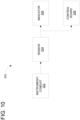
- FIG. 10 shows a block diagram of key components of a dental delivery system 300 to illustrate logical and functional relationships between key components at a high level.
- the delivery system 300 can include a fluid flow conduit 302, a sensor 304, an indicator 306, and a control board or control block assembly 308.
- a dental instrument or other device can be connected to the distal end of the conduit 302.
- Fluid such as coolant water or coolant solution for a rotary cutting handpiece
- the delivery system can include a flow control adjuster to adjust the flow rate of fluid through the conduit 302 and a connected handpiece.
- the sensor 304 can determine when the handpiece is in use, such as by sensing a predetermined motion of the instrument or the conduit 302.
- the sensor 304 is linked to the indicator 306, which can be illuminated to indicate which of a plurality of flow control adjusters can be used to adjust flow rate for the handpiece that is being used.
- the flow control adjuster can adjust the flow rate of air, water, or other fluids.
- the delivery system 300 is particularly well suited for adjusting the flow of water or other liquids since different flow rates of water or liquid are often desirable with different handpieces connected to the delivery system.
- the sensor 304 is linked to the indicator 306, and thus can transmit a signal, such as a fluid signal, digital signal, or other type of signal to the indicator 306.
- the sensor 304 can also be linked to control board 308, which can control other operations of the delivery system 300.
- FIG. 1 is a perspective view of one example of a dental chair assembly 100 having a dental chair 101, with which a delivery system, such as delivery system 140, is typically used.
- the dental chair assembly 101 which is sometimes also referred to as a patient chair or a treatment chair, is designed to accommodate a patient (not shown) comfortably, while allowing the patient to be positioned as needed relative to a dentist or other practitioner(s) during treatment
- the dental chair assembly 100 further includes a first movable arm 122 that can pivot or rotate (i.e., to the left or to the right) with respect to a first pivot mount 120 about a first upright pivot axis Pi.
- a second pivot mount 130 positioned on the longitudinal axis L and forward of the first pivot mount 120 that supports a second movable arm 132.
- the second movable arm 132 can pivot or rotate with respect to the second pivot mount 130 about a second upright pivot axis P 2 .
- the first movable arm 122 can be configured to support a delivery system, such as the continental delivery system 140 shown in FIG. 1 , a traditional delivery system, or another type of delivery system. The continental and traditional delivery systems are described in more detail below.
- the first movable arm 122 can also support various other equipment, such as a water supply container 124 or a tray 126.
- the first movable arm 122 is configured to have an adjustable height section that allows equipment attached at the distal end, such as the delivery system 140, to be raised and lowered, swung through an arc and retained in place at a desired location (such as, e.g., with a brake or other device) with ease.
- the second movable arm 132 can be configured to support other equipment, such as a dental light (not shown). Other alternative configurations are also possible, depending upon the particular operating requirements.
- the delivery system 140 refers to the device or devices that provide the necessary utilities and amenities to provide treatment to the patient (including but not limited to compressed air, water, suction, electricity, data, touch or other control for integrated devices, holders for instruments and other components, etc.).
- the delivery system 140 can include a control head 142 to provide handpieces at positions convenient for treatment and is movable, e.g., to provide space for ingress and egress from the chair assembly 101.
- the control head 142 can provide connections for one or more of liquid (e.g., water), compressed air, suction, electrical power, data, etc., various instruments and devices that use these connections, storage for the instruments and devices, and/or a display, among other components.
- the delivery system 140 shown is a continental style delivery system.
- the delivery system 140 includes a plurality of whip arms 144 that can be coupled to handpieces for use during a dental procedure (e.g., drills, polishers, etc.).
- Each of the whip arms 144 can be connected to a supply of air, liquid, or other media for operation of a particular handpiece to be coupled to the whip arm.
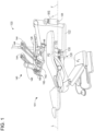
- FIG. 2 is a perspective view of the delivery system 140 adapted to have six whip arms 144.
- the control head 142 can include a plurality of holding areas 150 (such as six areas as shown) that are shaped to receive handpieces, such as handpieces 160, 162, when they are not in use.
- a handpiece 160 is shown in use with its whip arm 144 pulled away from its at rest position and handpieces 162, 164 are shown with their whip arms 144 in their at rest positions in holding areas 150. Also, there is a connection 166 for a handpiece shown in an at rest position. As a handpiece is removed from a holding area 150 and pulled away from the control head 142 during a dental procedure, the whip arm 144 can pivot away from the at rest position as shown for the whip arm for the whip arm for the handpiece 160. This allows a practitioner to have freedom of movement while using a handpiece during a procedure. When the whip arm 144 is not in the at rest position, it applies a gentle tugging force to a handpiece coupled to it.
- this force is not significant enough to interfere with the use of the handpiece during a procedure.
- this tugging force retracts the whip arm 144 to pivot back to the resting position such that the handpiece can be placed back into its holding area 150.
- the whip arm 144 does not apply a tugging force while the practitioner is using the handpiece.
- a retracting force acting on the whip can be triggered either actively by the practitioner (e.g., by quickly tugging the handpiece) or passively (e.g., after operation of the handpiece ceases).
- the control head 142 includes a plurality of flow control adjusters 148.
- the flow control adjusters 148 are rotatable knobs.
- the flow control adjusters 148 can be sliders or other types of adjusters.
- the flow control adjusters 148 can be used to control fluid flow rates to the various handpieces coupled to the whip arms 144.
- the control head 142 can also include an air flow control adjuster or air flow control knob 152, as best shown in FIG. 2 , to control air flow, such as coolant air for a rotary cutting handpiece, to one or more handpieces coupled to one or more whip arms 144.
- the delivery system 140 includes six whip arms 144 (see FIG. 2 ), four flow control adjusters 148a-d and one air flow control adjuster 152.
- Each of the four flow control adjusters 148a-d can be associated with one whip arm 144 to control fluid flow through a handpiece coupled to that whip arm.
- the air flow control adjuster 152 can control air flow through any or all of the handpieces coupled to the whip arms 144, including any or all of the handpieces associated with the flow control adjusters 148.
- the delivery system 140 can include more or fewer than six whip arms 144, more or fewer than four flow control adjusters 148, and more or fewer than one air flow control adjuster 152.
- each whip arm 144 can be associated with a flow control adjuster.
- the whip arms 144 and the knobs 148a-d are at dispersed locations relative to each other. That is, the whip arms 144 are positioned on the front of the delivery system 140 and the knobs 148 are positioned on the side of the delivery system. Accordingly, during a dental procedure, when a practitioner is using a particular handpiece, it may not be clear which knob is associated with the particular handpiece being used. Thus, if the practitioner wishes to adjust the flow rate of air or liquid to the handpiece being used, the practitioner may not be able to quickly identify which knob to adjust. This may cause the practitioner to adjust the wrong knob or to simply avoid adjusting the flow rate at all, thereby possibly not taking full advantage of the capabilities of the handpiece. Accordingly, indicator lights are associated with each of the flow control adjusters 148 as explained in further detail below.
- FIG. 4 shows a close-up view of the flow control knobs 148a, 148b, 148c, 148d and the air flow control knob 152.
- Each of the four flow control knobs can control fluid flow to one handpiece coupled to one of the whip arms 144.
- the indicators 149a, 149b, 149c, 149d comprise indicator lights that can be illuminated to indicate a particular flow control knob.
- each of the indicator lights is circularly shaped and encloses an associated flow control knob.
- the indicator lights can have a different shape and but are positioned adjacent to an associated flow control knob.
- the indicator lights comprise light-emitting diodes (LEDs).
- the indicator lights can comprise other illumination sources.
- light pipes can be used in conjunction with LEDs to distribute the illumination in a more visually pleasing fashion.
- the indicator light associated with the flow control adjuster that is associated with the handpiece being used is illuminated. This allows a practitioner to easily see which flow control knob controls the fluid flow rate to the particular handpiece being used. Thus, if the practitioner desires to adjust the fluid flow rate of the handpiece they are currently using, they need only look at the control knobs 148 and see which one is illuminated. For example, in FIGS. 3-4 , indicator light 149c is illuminated. This means that flow control knob 148c can be used to adjust the fluid flow to the handpiece that is currently being utilized. Additional details of the operation of the indicator lights are discussed in further detail below.
- the delivery system 140 can also comprise a touch interface control 146 connected to the control head 142.
- the touch interface control 146 can allow a practitioner to adjust various settings or features of the delivery system 140.
- the touch interface control 146 comprises a display screen that can display information about the operation of the delivery system, such as which handpieces are connected, the flow rates being supplied to the various handpieces, and other related information.
- the touch interface control 146 can be connected to a database and can display patient information.
- the touch interface control 146 can be a touchscreen that can allow a practitioner to enter information about a patient or to change control information related to the handpieces, such as fluid flow rates.
- the touch interface control 146 can comprise one or more buttons, sliders, or other control inputs.
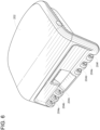
- FIG. 5 shows an alternative embodiment of a dental treatment assembly that has a dental unit or delivery system 200 with a traditional control head 202 instead of the continental control head 142.
- the delivery system 200 is coupled to the arm 122 in a similar manner as shown in FIG. 1 .
- the delivery system 200 includes the tray 126 and the touch interface control 146 as described above in connection with FIG. 1 .
- the delivery system 200 does not include any whip arms.
- the control head 202 includes a plurality of holding areas 204 to hold various handpieces. As best shown in FIG. 6 , the control head 202 of the illustrated embodiment includes six holding areas 204a-204f. In other embodiments, the control head 202 can have any number of holding areas.
- the control head 202 can also have flow control adjusters similar to control flow knobs 148a-148d that can control fluid flow through one or more handpieces coupled to the control head 202.
- the control head 202 can also have indicator lights similar to indicator lights 149-149d associated with the control knobs.
- handpieces When not in use, handpieces can be placed in the holding areas 204. Whenever a handpiece is removed from a holding area, an indicator light associated with a control knob that is associated with that particular handpiece is indicated, e.g., by being illuminated. Thus, a practitioner can easily see which control knob can be used to adjust the flow rate for the particular hand piece being used during a procedure. The operation of the indicator lights is discussed in further detail below.
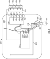
- FIG. 7 shows a circuit diagram for a fluid and electrical circuit 203 in the interior of a control head similar to the control head 202.
- a dental air/water syringe 164 is shown schematically in position in the holding area 204. Fluid can flow through conduit 302 to the handpiece 164.
- a pressure sensor for example, a hangar valve or handpiece holder valve
- the handpiece holder valve 205 is one form of the sensor 304.
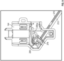
- the handpiece holder valve 205 comprises a pneumatic valve and a latch 208, as shown in FIG. 8 , and discussed below in greater detail.
- an air supply line 210 and a signal line 212 are connected to the pneumatic valve 206.
- the valve 206 also has a vent 216.
- a continuous feed of air at high pressure (about 80 psi) is supplied to the valve 206 through the air supply line 210.
- the latch 208 causes the vent 216 to close and the valve 206 to open such that air is allowed to pressurize the air supply line 210 the signal line 212, and a circuit control board 214, as shown in FIG. 7 .
- the valve 206 when the valve 206 is opened, other components within the control head 202 or elsewhere can be pressurized as well.
- the signal line 212 can be connected to a control block assembly 228, as shown in FIG. 7 .
- the control block assembly 228 can perform a number of function including enabling or disabling the flow of air, water, or other fluid flow to handpieces situated in their holding areas, opening or closing valves to turn a fluid flow on or off, or adjusting flow rates of fluids.
- a pressure transducer i.e., one of the pressure transducers 220, 221, 222, 223 as best shown in FIG. 9 , on the control board 214 converts the increased air pressure to an electrical signal that provides an input to an indicator controller circuit 219 by way of an electrical cable 229.
- the indicator controller circuit 219 is shown adjacent to the control adjusters 148a-d for purposes of illustration. In actuality, the controller circuit 219 can be positioned within the control assembly 228.
- control board 214 can disable certain functions of a handpiece situated in its holding area or other devices connected to the control board. In some embodiments, the control board 214 can send one or more signals to other devices to deactivate or disable certain functions of a handpiece situated in its holding area or certain functions of still other devices.
- the control board 214 can utilize either digital logic or software to drive the signals to indicator controller circuit 219 or other devices.
- Each of the pressure transducers 220, 221, 222, 223 can be associated with one of the four indicators 149a, 149b, 149c, 149d.
- the control board 214 can have additional pressure transducers.
- the pressure transducers 220, 221, 222, 223 can each output a signal to the indicator controller circuit 219 as described above.
- the transducers 220, 221, 222, 223 can send a signal to other components on the control board 214 or other devices.
- any of the pressure transducers 220, 221, 222, 223 send a signal associated with increased pressure to the indicator controller circuit 219, it means that the associated handpiece is not in use, causing the indicator light associated with the handpiece to not be illuminated.
- the latch 208 moves to an open position as shown in FIG. 8 .
- the corresponding pressure transducer on the control board 214 detects this reduced pressure, it sends a reduced pressure signal to the indicator controller circuit 219, which illuminates the indicator light associated with the handpiece that has been removed from the holding area.
- the pressure transducers on the control board 214, the valve 206, the air supply line 210, the signal line 212, and/or the latch 208 can be replaced with an electric switch or sensor, such as a microswitch capacitive sensor, an inductive sensor, an infrared sensor, or an optical sensor.
- the latch 208, or another presence sensor or device can cause a signal to be activated when a handpiece is removed from a holding area.
- the pressure in the signal line 212 is greater when the handpiece is in its holding area and lower when the handpiece is not in its holding area.
- another embodiment can involve switching this arrangement, such that a reduced pressure in the signal line 212 occurs when the handpiece is in its holding area and an increased pressure is in the signal line occurs when the handpiece is not in its holding area by reconfiguring the handpiece holder valve 205.
- the illumination of the indicators 149a, 149b, 149c, 149d would follow the same functionality described above, wherein the indicator associated with a handpiece removed from its holding area is illuminated, while all other indicators are not illuminated.
- control board 214 can be configured to provide additional functionality. For example, if two or more handpieces are both removed from their respective holding areas, the control board 214 can be configured to help avoid confusion for the practitioner by not illuminating any of the indicators 149a, 149b, 149c, 149d.
- FIG. 9 shows a cross sectional view of a lower portion of the whip arm 144 of the continental delivery system 140.
- the pneumatic valve 206 described above, is positioned within the interior of the whip arm 144 and/or the housing near where the whip arm 144 extends from an upper surface of the housing.
- the latch 208 can open and close the valve 206 in the same manner as discussed above.
- the air supply line 210 supplies constant air pressure to the valve 206.
- the latch 208 seals the vent 216 and air can flow from the air supply line 210 through the signal line 212 to the control board 214 in the same manner as described above with respect to the traditional delivery system.
- the pressure transducer can send a signal to the indicator controller circuit 219, which will not illuminate the indicator light associated with the whip arm.
- the latch 208 closes the valve 206 and uncovers the vent 216. This causes the signal to the pressure transducer on the control board 214 to be shut off, which in turn shuts off the signal to the indicator controller 219, which causes the appropriate indicator light to be illuminated to indicate which flow control knob can be used to control the handpiece being used.
Landscapes
- Health & Medical Sciences (AREA)
- Life Sciences & Earth Sciences (AREA)
- Animal Behavior & Ethology (AREA)
- General Health & Medical Sciences (AREA)
- Public Health (AREA)
- Veterinary Medicine (AREA)
- Dentistry (AREA)
- Epidemiology (AREA)
- Engineering & Computer Science (AREA)
- Water Supply & Treatment (AREA)
- Oral & Maxillofacial Surgery (AREA)
- Dental Tools And Instruments Or Auxiliary Dental Instruments (AREA)
Claims (10)
- Zahnärztliches Verabreichungssystem mit:mindestens einer ersten Fluidleitung (302) zum Zuführen von Fluid über das Verabreichungssystem zu einem Handstück (160, 162, 164), das mit einem distalen Ende der Leitung (302) verbunden ist;einer Vielzahl von Durchflusssteuerungseinstellern (148a-d), die an dem Verabreichungssystem an einer Stelle entfernt von der mindestens einen ersten Fluidleitung (302) angeordnet sind, wobei ein erster Durchflusssteuerungseinsteller der Vielzahl von Durchflusssteuerungseinstellern (148a-d) betreibbar ist, um eine Fluiddurchflussrate in der ersten Fluidleitung (302) zu ändern; undeinem Anzeigeschaltkreis, der eine Vielzahl von Sensoren (304) und eine Vielzahl von visuellen Anzeigen (149a-d; 306) aufweist, wobei jede der Vielzahl von visuellen Anzeigen benachbart zu einer jeweiligen der Vielzahl von Durchflusssteuerungseinstellern (148a-d) positioniert ist, wobei ein erster Sensor der Vielzahl von Sensoren (304) betreibbar ist, um eine erste visuelle Anzeige der Vielzahl von visuellen Anzeigen (149a-d; 306) in Reaktion auf eine vorbestimmte Bewegung der ersten Fluidleitung (302) auszulösen, um visuell anzuzeigen, dass der erste Durchflusssteuerungseinsteller der ersten Fluidleitung (302) zugeordnet ist.
- Zahnärztliches Verabreichungssystem nach Anspruch 1, wobei die Vielzahl der Durchflusssteuerungseinsteller (148a-d) eine Vielzahl von drehbaren Knöpfen aufweist.
- Zahnärztliches Verabreichungssystem nach Anspruch 1, das ferner mindestens einen Haltebereich (204) zum Halten eines Handstücks (164) aufweist, wobei der erste Sensor so betreibbar ist, dass er die erste Anzeige in Reaktion darauf auslöst, dass ein Handstück (164) aus einem Haltebereich (204) entfernt wird.
- Zahnärztliches Verabreichungssystem nach Anspruch 1, das ferner mindestens einen Peitschenarm (144) aufweist, der mit dem Handstück (160, 162, 164) gekoppelt ist, wobei der erste Sensor so betreibbar ist, dass er die erste optische Anzeige in Reaktion darauf auslöst, dass der Peitschenarm (144) aus einer Ruheposition geschwenkt wird.
- Zahnärztliches Verabreichungssystem nach Anspruch 1, wobei der erste Sensor ein Handstückhalterventil (205) aufweist.
- Zahnärztliches Verabreichungssystem nach Anspruch 5, wobei das Handstückhalterventil (205) ein pneumatisches Ventil (206) aufweist.
- Zahnärztliches Verabreichungssystem nach Anspruch 6, wobei das Handstückhalterventil (205) ferner eine Verriegelung (208) aufweist, die so ausgebildet ist, dass sie sich in Reaktion auf die vorbestimmte Bewegung der ersten Fluidleitung (302) bewegt und das Ventil (206) schließt.
- Zahnärztliches Verabreichungssystem nach Anspruch 7, wobei der Anzeigeschaltkreis ferner einen Druckübertrager (220, 221, 222, 223) aufweist, um ein pneumatisches Signal von dem pneumatischen Ventil (206) zu empfangen.
- Zahnärztliches Verabreichungssystem nach Anspruch 1, wobei die Vielzahl von visuellen Anzeigen (149a-d; 306) eine Vielzahl von Anzeigelampen aufweist, die jeweils einen der Vielzahl von Durchflusssteuerungseinstellern (148a-d) umgeben.
- Zahnärztliches Verabreichungssystem nach Anspruch 1, das ferner eine Berührungsschnittstellensteuerung (146) aufweist, die es einem Bediener ermöglicht, verschiedene Einstellungen oder Merkmale des Verabreichungssystems anzupassen, wobei die Berührungsschnittstellensteuerung (146) einen Anzeigebildschirm aufweist, der Informationen über den Betrieb des Verabreichungssystems anzeigen kann.
Applications Claiming Priority (2)
| Application Number | Priority Date | Filing Date | Title |
|---|---|---|---|
| US16/387,160 US11185389B2 (en) | 2019-04-17 | 2019-04-17 | Dental flow control adjuster with operation indicator |
| PCT/US2020/028578 WO2020214852A1 (en) | 2019-04-17 | 2020-04-16 | Dental flow control adjuster with operation indicator |
Publications (4)
| Publication Number | Publication Date |
|---|---|
| EP3813758A1 EP3813758A1 (de) | 2021-05-05 |
| EP3813758A4 EP3813758A4 (de) | 2022-04-13 |
| EP3813758B1 true EP3813758B1 (de) | 2023-08-09 |
| EP3813758C0 EP3813758C0 (de) | 2023-08-09 |
Family
ID=72833329
Family Applications (1)
| Application Number | Title | Priority Date | Filing Date |
|---|---|---|---|
| EP20791289.0A Active EP3813758B1 (de) | 2019-04-17 | 2020-04-16 | Zahnärztlicher durchflussregler mit betriebsanzeige |
Country Status (6)
| Country | Link |
|---|---|
| US (1) | US11185389B2 (de) |
| EP (1) | EP3813758B1 (de) |
| CN (1) | CN112601511A (de) |
| AU (1) | AU2020257235B2 (de) |
| CA (1) | CA3136645A1 (de) |
| WO (1) | WO2020214852A1 (de) |
Families Citing this family (4)
| Publication number | Priority date | Publication date | Assignee | Title |
|---|---|---|---|---|
| US11471356B2 (en) * | 2019-04-17 | 2022-10-18 | A-Dec, Inc. | Shelf for dental delivery system |
| US12097084B2 (en) * | 2020-12-31 | 2024-09-24 | A-Dec, Inc. | Automatic activation of flushing mode in dental systems |
| CN114767305B (zh) * | 2022-04-18 | 2024-01-05 | 漳州松霖智能家居有限公司 | 出水装置 |
| CN118217118B (zh) * | 2024-04-09 | 2025-02-28 | 广东精美医疗科技有限公司 | 医用工作台、牙科操作设备及医用工作台的控制方法 |
Family Cites Families (25)
| Publication number | Priority date | Publication date | Assignee | Title |
|---|---|---|---|---|
| US3691634A (en) | 1971-06-16 | 1972-09-19 | Dental Unit Construction | Dental unit construction |
| DE2339827B2 (de) * | 1973-08-06 | 1977-02-24 | A6 In 3-02 | Zahnaerztliches geraet |
| US4106198A (en) * | 1976-11-12 | 1978-08-15 | Pelton & Crane Company | Control arrangement for handpiece instrument |
| DK144993C (da) * | 1980-06-13 | 1982-12-20 | Flex Dental As | Tandlaegeapparat med et antal instrumenter tilsluttet en faelles styrekreds og et faelles betjeningsorgan |
| US4418334A (en) * | 1981-01-26 | 1983-11-29 | Burnett Dorothy K | Signal display system and luminaire apparatus for operating same |
| DK161490C (da) * | 1989-06-28 | 1991-12-23 | Den Flex As | Tandlaegeapparat med instrumentslanger for valgfri tilkobling af forskellige instrumenter |
| US5107899A (en) * | 1989-07-24 | 1992-04-28 | Gregory Murphy | Pneumatic control system |
| US5158453A (en) * | 1992-02-12 | 1992-10-27 | Knight Manufacturing Inc. | Apparatus for supporting and controlling fluid delivery to a dental handpiece |
| FR2692650B1 (fr) * | 1992-06-19 | 1994-08-19 | Taema | Système de surveillance de distribution de fluide vers un poste d'utilisation. |
| US6152735A (en) * | 1997-01-03 | 2000-11-28 | Meyer; Thomas C. | Whip arm mounting for dental delivery system control head |
| WO1998044861A1 (en) | 1997-04-08 | 1998-10-15 | American Dental Technologies, Inc. | Multipurpose dental unit |
| CA2294081C (en) * | 1998-05-04 | 2009-03-03 | Novoste Corporation | Intraluminal radiation treatment system |
| US6358048B1 (en) * | 1999-05-11 | 2002-03-19 | Michael A. Peralta | Pinch valve assembly |
| US6390815B1 (en) * | 1999-12-21 | 2002-05-21 | Gary J. Pond | Multiple solution dental irrigator |
| JP3937765B2 (ja) | 2001-07-25 | 2007-06-27 | ティアック株式会社 | インジケータ付きスイッチ装置 |
| US6692253B2 (en) * | 2001-10-12 | 2004-02-17 | Midmark Corporation | Instrument delivery head |
| JP2006346260A (ja) * | 2005-06-17 | 2006-12-28 | J Morita Tokyo Mfg Corp | 歯科用チェアユニット |
| US8506293B2 (en) * | 2005-12-28 | 2013-08-13 | Gary J. Pond | Ultrasonic endodontic dental irrigator |
| DE102007003471A1 (de) * | 2007-01-24 | 2008-07-31 | Kaltenbach & Voigt Gmbh | Vorrichtung zur Anzeige und Verwaltung von Systemparametern und Daten eines zahnärztlichen Behandlungsplatzes |
| JP5575508B2 (ja) * | 2010-03-05 | 2014-08-20 | 株式会社モリタ製作所 | 診療装置およびそのインスツルメントの管理制御方法 |
| US20130270251A1 (en) | 2012-04-16 | 2013-10-17 | Whirlpool Corporation | Lighted signals to provide direction to user |
| EP3711701A1 (de) * | 2012-11-02 | 2020-09-23 | Intuitive Surgical Operations, Inc. | Flussübertragungsverbinder und -systeme, flussunterscheidung sowie systeme und verfahren zur kartierung von flusszufuhrpfaden |
| US10905504B2 (en) * | 2015-06-02 | 2021-02-02 | Biomet 3I, Llc | Robotic device for dental surgery |
| JP6306642B2 (ja) | 2016-06-01 | 2018-04-04 | 株式会社吉田製作所 | 歯科用インスツルメントハンガー |
| JP7443064B2 (ja) * | 2017-04-28 | 2024-03-05 | ストライカー・コーポレイション | コンソールベースの外科システムのマッピングを示すシステム及び方法 |
-
2019
- 2019-04-17 US US16/387,160 patent/US11185389B2/en active Active
-
2020
- 2020-04-16 CN CN202080003788.5A patent/CN112601511A/zh active Pending
- 2020-04-16 EP EP20791289.0A patent/EP3813758B1/de active Active
- 2020-04-16 WO PCT/US2020/028578 patent/WO2020214852A1/en not_active Ceased
- 2020-04-16 AU AU2020257235A patent/AU2020257235B2/en active Active
- 2020-04-16 CA CA3136645A patent/CA3136645A1/en active Pending
Also Published As
| Publication number | Publication date |
|---|---|
| AU2020257235B2 (en) | 2021-03-04 |
| US20200330182A1 (en) | 2020-10-22 |
| US11185389B2 (en) | 2021-11-30 |
| WO2020214852A1 (en) | 2020-10-22 |
| EP3813758C0 (de) | 2023-08-09 |
| CA3136645A1 (en) | 2020-10-22 |
| CN112601511A (zh) | 2021-04-02 |
| EP3813758A4 (de) | 2022-04-13 |
| EP3813758A1 (de) | 2021-05-05 |
| AU2020257235A1 (en) | 2021-01-21 |
Similar Documents
| Publication | Publication Date | Title |
|---|---|---|
| AU2020257235B2 (en) | Dental flow control adjuster with operation indicator | |
| US20250213319A1 (en) | Surgical robotic system | |
| US20230277748A1 (en) | Remotely controlled suction/irrigation for surgery | |
| US20030232305A1 (en) | Universal-control mechanism for dental implements | |
| AU723523B2 (en) | Ophthalmic microsurgical system employing flash eeprom and reprogrammable modules | |
| JP2938176B2 (ja) | 手術制御システムのための遠隔制御コンソール | |
| WO2020092170A1 (en) | Surgical robotic system | |
| US10610309B2 (en) | Dental system | |
| PT1785122E (pt) | Dispositivo para o ajustamento da superfície de suporte de uma mesa de operações | |
| US5295825A (en) | Control system for dental handpieces | |
| US20100199203A1 (en) | Apparatus for Displaying and Managing System Parameters and Data Pertaining to a Dental Treatment Station | |
| JP5570801B2 (ja) | 医療用診療装置 | |
| US20090166306A1 (en) | Delivery channel | |
| EP3586755B1 (de) | Vorrichtung und verfahren zur steuerung von medizinischer ausrüstung | |
| US20250331823A1 (en) | Ultrasound probe with integrated controls | |
| KR20130015441A (ko) | 수술용 로봇 시스템 | |
| JP2010508104A (ja) | センサハンドルを有する医療装置 | |
| US3986262A (en) | Variable air actuated control unit for electrical dental handpieces | |
| US20090047626A1 (en) | Touch-operated brake release for a delivery unit articulating arm | |
| JP2001120492A (ja) | 内視鏡システム装置 | |
| US20090047617A1 (en) | Multiple position hand-piece holster for a delivery unit | |
| EP2667781B1 (de) | Steuersystem für klinische umgebungen | |
| WO1998044861A1 (en) | Multipurpose dental unit | |
| KR102861751B1 (ko) | 치과용 유니트 체어 | |
| KR102336843B1 (ko) | 유니트 체어 |
Legal Events
| Date | Code | Title | Description |
|---|---|---|---|
| STAA | Information on the status of an ep patent application or granted ep patent |
Free format text: STATUS: THE INTERNATIONAL PUBLICATION HAS BEEN MADE |
|
| PUAI | Public reference made under article 153(3) epc to a published international application that has entered the european phase |
Free format text: ORIGINAL CODE: 0009012 |
|
| STAA | Information on the status of an ep patent application or granted ep patent |
Free format text: STATUS: REQUEST FOR EXAMINATION WAS MADE |
|
| 17P | Request for examination filed |
Effective date: 20210127 |
|
| AK | Designated contracting states |
Kind code of ref document: A1 Designated state(s): AL AT BE BG CH CY CZ DE DK EE ES FI FR GB GR HR HU IE IS IT LI LT LU LV MC MK MT NL NO PL PT RO RS SE SI SK SM TR |
|
| REG | Reference to a national code |
Ref country code: DE Ref legal event code: R079 Free format text: PREVIOUS MAIN CLASS: A61G0015140000 Ipc: A61G0015160000 Ref country code: DE Ref legal event code: R079 Ref document number: 602020015570 Country of ref document: DE Free format text: PREVIOUS MAIN CLASS: A61G0015140000 Ipc: A61G0015160000 |
|
| A4 | Supplementary search report drawn up and despatched |
Effective date: 20220314 |
|
| RIC1 | Information provided on ipc code assigned before grant |
Ipc: A61C 1/00 20060101ALI20220308BHEP Ipc: A61G 15/16 20060101AFI20220308BHEP |
|
| DAV | Request for validation of the european patent (deleted) | ||
| DAX | Request for extension of the european patent (deleted) | ||
| GRAP | Despatch of communication of intention to grant a patent |
Free format text: ORIGINAL CODE: EPIDOSNIGR1 |
|
| STAA | Information on the status of an ep patent application or granted ep patent |
Free format text: STATUS: GRANT OF PATENT IS INTENDED |
|
| INTG | Intention to grant announced |
Effective date: 20230223 |
|
| GRAS | Grant fee paid |
Free format text: ORIGINAL CODE: EPIDOSNIGR3 |
|
| GRAA | (expected) grant |
Free format text: ORIGINAL CODE: 0009210 |
|
| STAA | Information on the status of an ep patent application or granted ep patent |
Free format text: STATUS: THE PATENT HAS BEEN GRANTED |
|
| AK | Designated contracting states |
Kind code of ref document: B1 Designated state(s): AL AT BE BG CH CY CZ DE DK EE ES FI FR GB GR HR HU IE IS IT LI LT LU LV MC MK MT NL NO PL PT RO RS SE SI SK SM TR |
|
| REG | Reference to a national code |
Ref country code: GB Ref legal event code: FG4D |
|
| REG | Reference to a national code |
Ref country code: CH Ref legal event code: EP |
|
| REG | Reference to a national code |
Ref country code: IE Ref legal event code: FG4D |
|
| REG | Reference to a national code |
Ref country code: DE Ref legal event code: R096 Ref document number: 602020015570 Country of ref document: DE |
|
| U01 | Request for unitary effect filed |
Effective date: 20230911 |
|
| U07 | Unitary effect registered |
Designated state(s): AT BE BG DE DK EE FI FR IT LT LU LV MT NL PT SE SI Effective date: 20230918 |
|
| PG25 | Lapsed in a contracting state [announced via postgrant information from national office to epo] |
Ref country code: GR Free format text: LAPSE BECAUSE OF FAILURE TO SUBMIT A TRANSLATION OF THE DESCRIPTION OR TO PAY THE FEE WITHIN THE PRESCRIBED TIME-LIMIT Effective date: 20231110 |
|
| PG25 | Lapsed in a contracting state [announced via postgrant information from national office to epo] |
Ref country code: IS Free format text: LAPSE BECAUSE OF FAILURE TO SUBMIT A TRANSLATION OF THE DESCRIPTION OR TO PAY THE FEE WITHIN THE PRESCRIBED TIME-LIMIT Effective date: 20231209 |
|
| PG25 | Lapsed in a contracting state [announced via postgrant information from national office to epo] |
Ref country code: RS Free format text: LAPSE BECAUSE OF FAILURE TO SUBMIT A TRANSLATION OF THE DESCRIPTION OR TO PAY THE FEE WITHIN THE PRESCRIBED TIME-LIMIT Effective date: 20230809 Ref country code: NO Free format text: LAPSE BECAUSE OF FAILURE TO SUBMIT A TRANSLATION OF THE DESCRIPTION OR TO PAY THE FEE WITHIN THE PRESCRIBED TIME-LIMIT Effective date: 20231109 Ref country code: IS Free format text: LAPSE BECAUSE OF FAILURE TO SUBMIT A TRANSLATION OF THE DESCRIPTION OR TO PAY THE FEE WITHIN THE PRESCRIBED TIME-LIMIT Effective date: 20231209 Ref country code: HR Free format text: LAPSE BECAUSE OF FAILURE TO SUBMIT A TRANSLATION OF THE DESCRIPTION OR TO PAY THE FEE WITHIN THE PRESCRIBED TIME-LIMIT Effective date: 20230809 Ref country code: GR Free format text: LAPSE BECAUSE OF FAILURE TO SUBMIT A TRANSLATION OF THE DESCRIPTION OR TO PAY THE FEE WITHIN THE PRESCRIBED TIME-LIMIT Effective date: 20231110 |
|
| PG25 | Lapsed in a contracting state [announced via postgrant information from national office to epo] |
Ref country code: PL Free format text: LAPSE BECAUSE OF FAILURE TO SUBMIT A TRANSLATION OF THE DESCRIPTION OR TO PAY THE FEE WITHIN THE PRESCRIBED TIME-LIMIT Effective date: 20230809 |
|
| PG25 | Lapsed in a contracting state [announced via postgrant information from national office to epo] |
Ref country code: ES Free format text: LAPSE BECAUSE OF FAILURE TO SUBMIT A TRANSLATION OF THE DESCRIPTION OR TO PAY THE FEE WITHIN THE PRESCRIBED TIME-LIMIT Effective date: 20230809 |
|
| PG25 | Lapsed in a contracting state [announced via postgrant information from national office to epo] |
Ref country code: SM Free format text: LAPSE BECAUSE OF FAILURE TO SUBMIT A TRANSLATION OF THE DESCRIPTION OR TO PAY THE FEE WITHIN THE PRESCRIBED TIME-LIMIT Effective date: 20230809 Ref country code: RO Free format text: LAPSE BECAUSE OF FAILURE TO SUBMIT A TRANSLATION OF THE DESCRIPTION OR TO PAY THE FEE WITHIN THE PRESCRIBED TIME-LIMIT Effective date: 20230809 Ref country code: ES Free format text: LAPSE BECAUSE OF FAILURE TO SUBMIT A TRANSLATION OF THE DESCRIPTION OR TO PAY THE FEE WITHIN THE PRESCRIBED TIME-LIMIT Effective date: 20230809 Ref country code: CZ Free format text: LAPSE BECAUSE OF FAILURE TO SUBMIT A TRANSLATION OF THE DESCRIPTION OR TO PAY THE FEE WITHIN THE PRESCRIBED TIME-LIMIT Effective date: 20230809 Ref country code: SK Free format text: LAPSE BECAUSE OF FAILURE TO SUBMIT A TRANSLATION OF THE DESCRIPTION OR TO PAY THE FEE WITHIN THE PRESCRIBED TIME-LIMIT Effective date: 20230809 |
|
| REG | Reference to a national code |
Ref country code: DE Ref legal event code: R097 Ref document number: 602020015570 Country of ref document: DE |
|
| U20 | Renewal fee for the european patent with unitary effect paid |
Year of fee payment: 5 Effective date: 20240424 |
|
| PLBE | No opposition filed within time limit |
Free format text: ORIGINAL CODE: 0009261 |
|
| STAA | Information on the status of an ep patent application or granted ep patent |
Free format text: STATUS: NO OPPOSITION FILED WITHIN TIME LIMIT |
|
| 26N | No opposition filed |
Effective date: 20240513 |
|
| PG25 | Lapsed in a contracting state [announced via postgrant information from national office to epo] |
Ref country code: MC Free format text: LAPSE BECAUSE OF FAILURE TO SUBMIT A TRANSLATION OF THE DESCRIPTION OR TO PAY THE FEE WITHIN THE PRESCRIBED TIME-LIMIT Effective date: 20230809 |
|
| PG25 | Lapsed in a contracting state [announced via postgrant information from national office to epo] |
Ref country code: MC Free format text: LAPSE BECAUSE OF FAILURE TO SUBMIT A TRANSLATION OF THE DESCRIPTION OR TO PAY THE FEE WITHIN THE PRESCRIBED TIME-LIMIT Effective date: 20230809 |
|
| REG | Reference to a national code |
Ref country code: CH Ref legal event code: PL |
|
| PG25 | Lapsed in a contracting state [announced via postgrant information from national office to epo] |
Ref country code: CH Free format text: LAPSE BECAUSE OF NON-PAYMENT OF DUE FEES Effective date: 20240430 |
|
| PG25 | Lapsed in a contracting state [announced via postgrant information from national office to epo] |
Ref country code: IE Free format text: LAPSE BECAUSE OF NON-PAYMENT OF DUE FEES Effective date: 20240416 |
|
| U20 | Renewal fee for the european patent with unitary effect paid |
Year of fee payment: 6 Effective date: 20250425 |
|
| PGFP | Annual fee paid to national office [announced via postgrant information from national office to epo] |
Ref country code: GB Payment date: 20250423 Year of fee payment: 6 |
|
| PG25 | Lapsed in a contracting state [announced via postgrant information from national office to epo] |
Ref country code: CY Free format text: LAPSE BECAUSE OF FAILURE TO SUBMIT A TRANSLATION OF THE DESCRIPTION OR TO PAY THE FEE WITHIN THE PRESCRIBED TIME-LIMIT; INVALID AB INITIO Effective date: 20200416 |
|
| PG25 | Lapsed in a contracting state [announced via postgrant information from national office to epo] |
Ref country code: HU Free format text: LAPSE BECAUSE OF FAILURE TO SUBMIT A TRANSLATION OF THE DESCRIPTION OR TO PAY THE FEE WITHIN THE PRESCRIBED TIME-LIMIT; INVALID AB INITIO Effective date: 20200416 |