EP3813699B1 - Knochenplattensystem - Google Patents
Knochenplattensystem Download PDFInfo
- Publication number
- EP3813699B1 EP3813699B1 EP19824755.3A EP19824755A EP3813699B1 EP 3813699 B1 EP3813699 B1 EP 3813699B1 EP 19824755 A EP19824755 A EP 19824755A EP 3813699 B1 EP3813699 B1 EP 3813699B1
- Authority
- EP
- European Patent Office
- Prior art keywords
- bone plate
- sliders
- bone
- actuator
- slider
- Prior art date
- Legal status (The legal status is an assumption and is not a legal conclusion. Google has not performed a legal analysis and makes no representation as to the accuracy of the status listed.)
- Active
Links
Images


Classifications
-
- A—HUMAN NECESSITIES
- A61—MEDICAL OR VETERINARY SCIENCE; HYGIENE
- A61B—DIAGNOSIS; SURGERY; IDENTIFICATION
- A61B17/00—Surgical instruments, devices or methods
- A61B17/56—Surgical instruments or methods for treatment of bones or joints; Devices specially adapted therefor
- A61B17/58—Surgical instruments or methods for treatment of bones or joints; Devices specially adapted therefor for osteosynthesis, e.g. bone plates, screws or setting implements
- A61B17/68—Internal fixation devices, including fasteners and spinal fixators, even if a part thereof projects from the skin
- A61B17/80—Cortical plates, i.e. bone plates; Instruments for holding or positioning cortical plates, or for compressing bones attached to cortical plates
- A61B17/8033—Cortical plates, i.e. bone plates; Instruments for holding or positioning cortical plates, or for compressing bones attached to cortical plates having indirect contact with screw heads, or having contact with screw heads maintained with the aid of additional components, e.g. nuts, wedges or head covers
- A61B17/8047—Cortical plates, i.e. bone plates; Instruments for holding or positioning cortical plates, or for compressing bones attached to cortical plates having indirect contact with screw heads, or having contact with screw heads maintained with the aid of additional components, e.g. nuts, wedges or head covers wherein the additional element surrounds the screw head in the plate hole
-
- A—HUMAN NECESSITIES
- A61—MEDICAL OR VETERINARY SCIENCE; HYGIENE
- A61B—DIAGNOSIS; SURGERY; IDENTIFICATION
- A61B17/00—Surgical instruments, devices or methods
- A61B17/56—Surgical instruments or methods for treatment of bones or joints; Devices specially adapted therefor
- A61B17/58—Surgical instruments or methods for treatment of bones or joints; Devices specially adapted therefor for osteosynthesis, e.g. bone plates, screws or setting implements
- A61B17/68—Internal fixation devices, including fasteners and spinal fixators, even if a part thereof projects from the skin
- A61B17/80—Cortical plates, i.e. bone plates; Instruments for holding or positioning cortical plates, or for compressing bones attached to cortical plates
- A61B17/8004—Cortical plates, i.e. bone plates; Instruments for holding or positioning cortical plates, or for compressing bones attached to cortical plates with means for distracting or compressing the bone or bones
-
- A—HUMAN NECESSITIES
- A61—MEDICAL OR VETERINARY SCIENCE; HYGIENE
- A61B—DIAGNOSIS; SURGERY; IDENTIFICATION
- A61B17/00—Surgical instruments, devices or methods
- A61B17/56—Surgical instruments or methods for treatment of bones or joints; Devices specially adapted therefor
- A61B17/58—Surgical instruments or methods for treatment of bones or joints; Devices specially adapted therefor for osteosynthesis, e.g. bone plates, screws or setting implements
- A61B17/68—Internal fixation devices, including fasteners and spinal fixators, even if a part thereof projects from the skin
- A61B17/80—Cortical plates, i.e. bone plates; Instruments for holding or positioning cortical plates, or for compressing bones attached to cortical plates
- A61B17/808—Instruments for holding or positioning bone plates, or for adjusting screw-to-plate locking mechanisms
-
- A—HUMAN NECESSITIES
- A61—MEDICAL OR VETERINARY SCIENCE; HYGIENE
- A61B—DIAGNOSIS; SURGERY; IDENTIFICATION
- A61B17/00—Surgical instruments, devices or methods
- A61B17/56—Surgical instruments or methods for treatment of bones or joints; Devices specially adapted therefor
- A61B17/58—Surgical instruments or methods for treatment of bones or joints; Devices specially adapted therefor for osteosynthesis, e.g. bone plates, screws or setting implements
- A61B17/68—Internal fixation devices, including fasteners and spinal fixators, even if a part thereof projects from the skin
- A61B17/84—Fasteners therefor or fasteners being internal fixation devices
- A61B17/86—Pins or screws or threaded wires; nuts therefor
-
- A—HUMAN NECESSITIES
- A61—MEDICAL OR VETERINARY SCIENCE; HYGIENE
- A61B—DIAGNOSIS; SURGERY; IDENTIFICATION
- A61B17/00—Surgical instruments, devices or methods
- A61B2017/00831—Material properties
- A61B2017/00862—Material properties elastic or resilient
-
- A—HUMAN NECESSITIES
- A61—MEDICAL OR VETERINARY SCIENCE; HYGIENE
- A61B—DIAGNOSIS; SURGERY; IDENTIFICATION
- A61B17/00—Surgical instruments, devices or methods
- A61B2017/00831—Material properties
- A61B2017/00867—Material properties shape memory effect
-
- A—HUMAN NECESSITIES
- A61—MEDICAL OR VETERINARY SCIENCE; HYGIENE
- A61B—DIAGNOSIS; SURGERY; IDENTIFICATION
- A61B17/00—Surgical instruments, devices or methods
- A61B17/56—Surgical instruments or methods for treatment of bones or joints; Devices specially adapted therefor
- A61B2017/564—Methods for bone or joint treatment
Definitions
- the present disclosure relates to bone plate systems that are secured to bones and, more specifically, to bone plate systems for being secured to bones and compressing the bones together to facilitate fusion of the bones.
- Bone plate systems are known for stabilizing bones.
- the term "bone” refers to a whole bone or a portion of a bone.
- the bones stabilized by a bone plate system may be, for example, portions of a single bone such as a broken clavicle bone or separate vertebrae.
- One application of bone plate systems is to secure two or more vertebrae together with an intervertebral implant between the vertebrae.
- Another application of bone plate systems is to fuse portions of a bone that have been separated by a break or a cut.
- a bone plate system may be used to facilitate fusion of portions of a broken bone of a clavicle, scapula, foot, or other extremity.
- US 2014/0066997 A1 describes a retaining mechanism for use in affixing a stratum to bone.
- the mechanism comprises a stratum comprising a first surface, a second surface, and a hole extending between the two surfaces.
- the hole has a central longitudinal axis extending substantially perpendicular to the two surfaces.
- the retaining element comprises a first position that permits a fastener to be passed through the hole, a second position that at least partially overlaps the hole, and a spring element.
- the spring element is configured to engage the stratum, configured to move in a direction substantially perpendicular to the central longitudinal axis of the hole when the retaining element moves between its first and second positions, and configured to engage the retaining element to help maintain the retaining element in its second position to help prevent inadvertent backing out of the fastener after it has been fully inserted into the hole.
- US 2013/0304067 A1 describes a bone fracture plate assembly including female and male plate portions.
- the female plate portion has a post, a female dovetail, and an extending arm with a group of ratchet teeth.
- the male plate portion has two upstanding posts, a male dovetail for coupling to the female dovetail so that the plate portions move linearly with respect to each other, a slot for the arm, and a pawl for engaging the ratchet teeth.
- a spring coupled to the posts of the plate portions, dynamically connects the plate portions by applying a compressive load therebetween.
- the spring has a pair of elongated ears, each defining a slot to allow for relative movement of the plate portions.
- the ratchet teeth are engaged by the pawl to retain the plate portions together, and the spring mounts on the posts of the plate portions such that the spring biases the plate portions together.
- a bone plate system that includes a bone plate having a plurality of elongated through openings. Each elongated through opening has a pair of end portions across the through opening from each other.
- the bone plate system includes a plurality of bone screws each having a head portion and a shank portion, the shank portion being configured to be driven into a bone.
- the bone plate system includes a plurality of sliders in the elongated through openings of the bone plate. Each slider has a throughbore configured to receive the head portion of one of the bone screws.
- the sliders and bone screw head portions received therein are shiftable within the elongated through openings relative to the bone plate.
- the bone plate system includes at least one resilient member for being configured to apply a biasing force to each of the sliders to urge the slider toward one end portion of a respective through opening.
- the bone plate system includes at least one actuator having an interference position in which the actuator inhibits shifting of the sliders toward the one end portion of the respective through opening.
- the at least one actuator also has a clearance position in which the actuator permits the at least one resilient member to urge the sliders and the bone screws received therein toward the one end portion of the through openings.
- the bone plate system may be secured to bones and the at least one actuator moved from the interference position to the clearance position to cause the at least one resilient member to urge the sliders and bone screws along the elongated through openings and compress the bones together.
- the bone plate is made of a rigid material such as titanium to resist post-surgical loading from the bones and keep the bones compressed together.
- An embodiment of the present invention provides a bone plate system for securing a pair of bones.
- the bone plate system includes a bone plate, elongated through openings of the bone plate, and a pair of bone screws for securing the bone plate to the bones.
- the bone plate system further includes a pair of sliders in the elongated through openings that each have a through bore for receiving a bone screw and at least one actuator configured to be clamped between the sliders and the bone plate.
- the bone plate system includes at least one resilient member configured for applying a biasing force to the sliders to urge the sliders against the at least one actuator and cause the sliders to clamp the at least one actuator between the sliders and the bone plate.
- the at least one actuator is removable from being clamped between the sliders and the bone plate so that the biasing force urges each slider and the bone screw therein toward the other slider and bone screw for compressing the bones together.
- the bone plate system thereby provides a secure assembly of the at least one actuator clamped between the sliders and the bone plate which improves the ease of handling of the bone plate system during installation.
- the at least one resilient member provides an easy-to-use approach for applying a biasing force against the bones by removing the at least one actuator from the bone plate.
- the bone plate system of the present invention can be usefully applied in a method for compressing a pair of bones as described herein (not part of the claimed invention).
- the method includes positioning a bone plate against bones and driving shanks of bone screws into through bores of sliders in elongated through openings of the bone plate and into engagement with the bones.
- the method includes removing at least one actuator from the bone plate and permitting at least one resilient member to urge the sliders and bone screw head portions therein toward each other along the elongated through openings of the bone plate and compress the bones together.
- the method can be utilized to quickly secure the bone plate to the bones by driving the bone screws into through bores of the sliders and compress the bones by removing the at least one actuator from the bone plate.
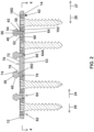
- a bone plate system 10 that includes a bone plate 12 having one or more through openings 14 therein that receive one or more slider assemblies 16.
- the slider assemblies 16 each include a slider 18 and one or more resilient members such as wires 20, 22 (see FIG. 4 ).
- the wires 20, 22 have a loaded configuration wherein the wires 20, 22 apply a biasing force to the sliders 18 which urges each of the sliders 18 toward one end portion 64 (see FIG. 2 ) of the respective through opening 14.
- the bone plate system 10 also includes at least one actuator, such as spacers 36, which resist movement of the sliders 18 toward the one end portion 64 of the respective through opening 14 and keep the wires 20, 22 in a loaded configuration.
- the sliders 18 include sliders 18A, 18B for being secured to a first bone 86 (see FIG. 3 ) and sliders 18C, 18D for being secured to a second bone 84.
- the sliders 18 each include one or more through bores 32 that receive bone anchors such as bone screws 30.
- the bone plate 12 is positioned against the bones 84, 86 and the bone screws 30 are driven into the through bores 32 of the sliders 18 and into the bones 84, 86 until head portions 34 of the bone screws 30 are seated in the through bores 32 of the sliders 18 as shown in FIG. 1 .
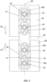
- a user operates the at least one actuator to cause the bone plate system 10 to compress the bones 84, 86.
- the user operates the at least one actuator by removing the spacers 36 from the bone plate 12 generally in direction 38.
- the wires 20, 22 of the slider assemblies 16 can unload and urge the sliders 18A, 18B and bone screws 30 therein in direction 24 and urge the sliders 18C, 18D and bone screws 30 therein in direction 26.
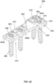
- the spacers 36 each include a head 40 and a body 42.
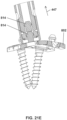
- the head 40 is configured to be engaged by an actuator removal instrument such as spacer removal instrument 50 (see FIG. 19 ).
- the body 42 of the spacer 36 is sized to extend into one of the through openings 14 and separate the slider 18D from a laterally extending wall 52 of the bone plate 12. More specifically, the body 42 includes flats 54, 56 with the flat 54 engaging a flat surface 58 of the slider 18D and the flat 56 engaging a flat surface 60 of the wall 52.
- the presence of the spacer body 42 in the through opening 14 keeps the slider 18D at one end portion 62 of the through bore 32 and maintains the wires 20, 22 in a loaded configuration (see FIG. 4 ).
- the biasing force provided by the wires 20, 22 clamps the body 42 of the spacer 36 between the slider 18D and the wall 52 of the bone plate 12.
- the wires 20, 22 can shift slider 18D in direction 24 toward an opposite end portion 64 of the through opening 14.
- the sliders 18A, 18B, 18C operate in a similar manner as discussed with respect to slider 18D.
- the bone plate 12, sliders 18, and spacers 36 are made of rigid materials meaning that they are not intended to deform during normal installation and post-surgical use of the bone plate system 10.
- the bone plate 12, sliders 18, and spacers 36 are made of a metallic material such as titanium.
- the rigidity of the spacers 36 keeps the wires 20, 22 from being able to shift to the unloaded configuration thereof while the spacers 36 are present in the through openings 14.
- the wires 20, 22 are made of a superelastic material.
- the superelastic material may be a metallic material such as superelastic nitinol.
- the wires 20, 22 may be made of superelastic nitinol and may each have a diameter of 0.028 inches.
- the bone plate system 10 utilizing these wires 20, 22 may provide 63 lbs of compressive force.
- the biasing force of the wires 20, 22 increases rapidly with relatively small increases in diameter.
- the bone plate system 10 utilizing superelastic nitinol wires 20, 22 each having a diameter of 0.035 inches may provide 141 lbs of compressive force.
- the terms loaded configuration and unloaded configuration with reference to wires 20, 22 are relative terms wherein the wires 20, 22 are loaded or deformed more in the loaded configuration than in the unloaded configuration.
- the wires 20, 22 are described as being in the unloaded configuration, it is not intended that the wires 20, 22 must be completely unloaded, just that the wires 20, 22 are less loaded or deformed than when the wires are in the loaded configuration.
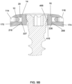
- the spacer 36 is configured to facilitate removal of the spacer 36 by the spacer removal instrument 50.
- the spacer 36 includes a shoulder 70 that seats on an upper surface 72 of the bone plate 12.
- the shoulder 70 positions an underside surface 74 of the head 40 at distance 76 above the bone plate upper surface 72.
- the distance 76 creates a gap 78 of the bone plate 12/spacer 36 assembly into which a portion of the instrument 50 may fit and engage the underside surface 74 of the head 40.
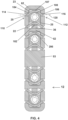
- the bone plate 12 has a lower surface 80 opposite the upper surface 72 for being positioned against the bones 84, 86.
- the lower surface 80 may have a concave curvature to compliment the external surfaces of the bones 84, 86.
- the bone plate 12 has been positioned against the bones 84, 86 which are separated by a small gap 88.
- the bone screws 30 have been driven into the through bores 32 of the sliders 18.
- the bone plate 12 has a longitudinal axis 90 and all of the sliders 18A, 18B, 18C, 18D are aligned along the longitudinal axis. This provides a small footprint for the bone plate 12 on the bones 84, 86 and is well suited for narrow bones such as bones of the clavicle, foot, or other extremities.
- the spacers 36 are connected to bone plate 12 and hold the sliders 18 at the end portion 62 of the through openings 14. Because the sliders 18 are held at the end portion 62 of the through openings 14, the sliders 18 maintain the wires 20, 22 in the loaded configuration.
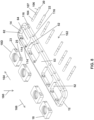
- the wires 20, 22 extend through passageways 23, 25 (see FIG. 8 ) of the sliders 18 and have a bent configuration around walls 100, 102 of the sliders 18.
- the wires 20, 22 each have an intermediate portion 107 secured to the slider 18.
- the intermediate portion 107 is secured to the slider 18 such as by forming a dimple in an upper surface 109 (see FIG. 11 ) of an upper wall 111 of the slider 18 which deforms the upper wall 111 into engagement with the intermediate portion 107.
- the wires 20, 22 include end portions 104, 106 extending out of the passageways 23, 25 and are received in wire-receiving portions 110, 112 of the bone plate 12.
- the wire-receiving portions 110, 112 include pairs of apertures 114, 116 that receive wire end portions 104, 106. More specifically, the end portions 104, 106 of the wire 20 extend out of the passageway 23 and into apertures 114, 116 of the bone plate 12. Likewise, the end portions 104, 106 of the wire 22 extend out of the passageway 25 and into apertures 114, 116 of the bone plate 12.
- the wires 20, 22 support the sliders 18 in the through openings 14.
- the wires 20, 22 are made of a material and have a diameter sufficient to provide pull-through resistance for the sliders 18 such that the sliders 18 and bone screws 30 therein stay within the through openings 14 of the bone plate 12 despite loads applied to the bone screws 30 by the bones 84, 86.
- the spacers 36 have been removed from the bone plate 12 which permits the wires 20, 22 to unload by straightening.
- the unloading wires 20, 22 convert the preload or stored potential energy within the wires 20, 22 into biasing forces which shift the sliders 18A, 18B in direction 24 and sliders 18C, 18D in direction 26.
- the shifting of the sliders 18 in directions 24, 26 urges the bones 84, 86 together and removes the gap 88 therebetween.
- the wires 20, 24 are able to shift the sliders 18 from the end portions 62 of the through openings 14 to the opposite end portions 64 of the through openings 14. Further, depending on patient anatomy, the wires 20, 24 may urge the sliders 18 less than the entire distance along the through openings 14. If the sliders 18 are spaced from the laterally extending walls of the bone plate 12 at the end portion 64 of the through opening 14, the wires 20, 22 will be bent and will continue to apply a biasing force to the sliders 18.
- the wires 20, 22 are shown in an unloaded configuration after the spacers 36 have been removed and the wires 20, 22 have urged the sliders 18 to the end portions 64 of the through openings 14.
- the wires 20, 22 are substantially straight with the end portions 104, 106 being generally coaxial with the intermediate portion 107.
- the wires 20, 22 may still be bent in unloaded configuration such as if the patient's anatomy prevents the sliders 18 from shifting the full distance across the through openings 14.
- the end portions 104, 106 wiggle or pivot from a transversely extending orientation relative to each other to the coaxial orientation relative to each other as the wires 20, 22 shift from the loaded configuration to the unloaded configuration.
- the wires 20, 22 may be made of a super-elastic material such as nitinol which has a stress-strain graph 150.
- the nitinol wires 20, 22 have a first characteristic (e.g. spring constant) when they are biasing the sliders 18 in directions 24, 26 (see FIG. 2 ) toward the end portions 64 of the through openings 14 such as after the spacers 36 are removed from the bone plate 12.
- the nitinol wires 20, 22 have a second characteristic (e.g. spring constant) that is different than the first characteristic when the sliders 18 are shifted in directions 27, 29 toward the end portions 62 of the through openings 14 such as if the bones 84, 86 are being urged apart due to patient movement.
- the different first and second characteristics cause the wires 20, 22 to provide a greater resistance force to movement of the sliders 18A, 18B in direction 29 and sliders 18C, 18D in direction 27 than the force the wires 20, 22 apply against the sliders 18 to shift the sliders 18A, 18B in direction 24 and sliders 18C, 18D in direction 26.
- the higher resistance to shifting of the sliders 18 in directions 27, 29 causes the wires 20, 22 to act as one-way slide control mechanisms that effectively limit sliding movement of the sliders 18 to directions 24, 26 while inhibiting sliding movement of the sliders 18 in directions 29, 27.
- the different characteristics of the nitinol wires 20, 22 may be due to the stressinduced formation of some martensite in the superelastic nitinol of the wires 20, 22 above the normal temperature of martensite formation. Because the martensite has been formed above its normal formation temperature, the martensite reverts immediately to undeformed austenite as stress is removed. Austenite is higher strength than martensite and is stronger against bending of the nitinol wires 20, 22 back toward their loaded configuration.
- the wires 20, 22 of the slider 18D resist this movement and the stress and strain within the wires 20, 22 jumps to position D in the stress-strain graph 150.
- the jump to the upper band of the stress-strain graph 150 indicates that the stress in the material is much higher which translates into greater resistance to bending of the wires 20, 22 back toward their loaded configuration.
- the sliders 18 and wires 20, 22 of each slider are shown prior to assembly with the bone plate 12.
- the sliders 18 are inserted in direction 160 into the through openings 14.
- the sliders 18 are positioned in their unloaded positions, i.e., at the end portions 64 of the through openings 14.
- the wires 20, 22 are provided in a straight, unloaded configuration.
- the end portions 104 of the wires 20, 22 are advanced in direction 162 through apertures 116 of the bone plate 12, through the passageways 23, 25 of the sliders 18, and into the through apertures 114 of the opposite side of the bone plate 12.
- the wires 20, 22 are thereby positioned so that the intermediate portion 107 of each wire 20, 22 extends through the respective passageway 23, 25, the end portion 104 of each wire 20 is received in one of the through apertures 114, and the end portion 106 of each wire 20, 22 is received in one of the through apertures 116.
- the sliders 18 are then shifted in preloading directions 164, 166 toward the loaded positions thereof, i.e., toward end portions 62 (see FIG. 2 ) of the through openings 14. Shifting of the sliders 18 in the preloading directions 164, 166 loads or bends the wires 20, 22 and creates gaps 64A (see FIG. 2 ) between the sliders 18 and the laterally extending walls 52, 53 of the bone plate 12.
- the shifting of the sliders 18 in preloading directions 164, 166 may be performed by a technician utilizing a tool or an automated machine as some examples.
- the spacers 36 are generally advanced in a direction 160 into the gaps 64A between the sliders 18 and the nearby bone plate laterally extending walls 52, 53 while the sliders 18 are held in the loaded position thereof by the technician or automated machine.
- the sliders 18 are released and the wires 20, 22 of each slider 18 urge the sliders 18 against the spacers 36 which clamps the spacers 36 between the sliders 18 and the laterally extending bone plate walls 52, 53.
- the process of shifting the sliders 18 to the loaded position and connecting the spacers 36 to the bone plate 12 may be performed on all of the sliders 18 at once, or may be performed on fewer than all of the sliders 18 (e.g., one or more) at a time.
- the bone plate 12 includes an end wall 170 opposite the laterally extending wall 52 and side walls 172, 174 through which the apertures 114, 116 extend.
- the apertures 114, 116 have a varying profile throughout to accommodate the movement of the end portions 104, 106 of the wires 20, 22.
- each through opening 14 has a longitudinal axis 175 extending between the end portions 62, 64 of the through opening 14.
- the through aperture 114 includes a narrow portion 180 having a distance 182 thereacross and an enlarged portion 184 having a distance 186 thereacross that is larger than the distance 182.
- the enlarged portion 184 provides clearance for the end portion 104 of the wire 20 to move from the oblique or transverse orientation thereof when the wires 20, 22 are in the loaded configuration (see FIG. 4 ) to the parallel or coaxial orientation when the wires 20, 22 are in the unloaded configuration thereof (see FIG. 6 ).
- the side wall 172 also includes features that support the end portion 104 of the wires 20, 22 while minimizing stress imparted to the wires 20, 22.
- the side wall 172 includes an angled surface 190 that extends at an acute angle 192 relative to an axis 120 extending laterally through the apertures 114, 116.
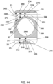
- the sliders 18 have a generally rectangular configuration and through openings 14 have a generally rectangular configuration that is longer than the sliders 18 to permit the sliders 18 and bone screws 30 therein to slide longitudinally within the through opening 14 along the bone plate 12.
- the slider 18 includes a body 220 having lateral sides 222, 224.
- the sides 222, 224 include flat surfaces 226, 227 for facing flat surfaces 208, 210 of the bone plate side walls 172, 174 as shown in FIG. 9B .
- the passageways 23, 25 of the slider 18 includes openings 230, 232 that open to the sides 222, 226 (see FIG. 14 ).
- the facing flat surfaces 208, 226 and 210, 227 of the sliders 18 and the bone plate 12 resist turning of the sliders 18 within the through openings 14.
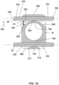
- the side walls 172, 174 of the bone plate 12 include wall portions 200, 202 above and below the wires 20, 22 when the wires extend through the apertures 114, 116.
- the wires 20, 22 support the sliders 18 within the through openings 14 of the bone plate 12 against movement of the sliders 18 in directions 204, 205 out of the plane of the bone plate 12.
- the wires 20, 22 are made of a material and have an adequate diameter to be sufficiently strong in shear to resist the loading applied to the sliders 18 by the bone screws 30.
- the lateral sides 222, 224 of the slider 18 extend longitudinally between front and rear sides 240, 242. Further, the passageways 23, 25 extend through the slider 18 and include an angled surface 298 and a rounded surface 316 that lead into the passageways 23, 25 from the sides 222, 224.
- the passageway 25 includes enlarged side portions 254, 256 for receiving the wire 22 and permitting the end portions 104, 106 space to pivot or wiggle as the wire 22 straightens toward the undeflected configuration thereof.
- the passageway 23 of the slider 18 varies in size as the passageway 23 extends laterally across the slider 18 to provide support to the wire 20 when wire 20 is in deflected configuration thereof and provide clearance for the wire 20 as the wire 20 moves from the deflected configuration to the undeflected configuration.
- the passageway 23 includes enlarged side portions 232, 230 and an intermediate portion 270.
- the passageway 23 has a first distance 272 thereacross at the enlarged side portion 232, a second distance 274 thereacross intermediate the enlarged portion 232 and the intermediate portion 270, and a third distance 276 at the intermediate portion 270.
- the distance 272 is greater than the distance 274 which is in turn greater than the distance 276. Similar sizing exists at the enlarged side portions 230.
- the slider 18 includes a wall 280 that abuts against or is a close proximity to a laterally extending wall of the bone plate 12 such as walls 52, 170 when the slider 18 is in the loaded position thereof.
- the slider 18 also includes the wall 100 extending around the through bore 32.
- the wall 280 may extend generally straight laterally across the slider while the wall 100 includes an angled surface 290, a rounded corner 292, an intermediate support surface 294, a rounded corner 296 and an angled surface 298 at the passageway 23.
- the angled surfaces 290, 298 each extend an angle 300 relative to the lateral axis 302 that extends straight through the passageway 23.
- the passageway 25 includes the enlarged side portions 254, 256 and a wall 102 extending generally laterally across the slider 18.
- the slider 18 also includes the wall 102 having a rounded surface 312, an intermediate support surface 314, and a rounded surface 316.
- the passageway 35 varies in size as the passageway 25 extends through the slider 18 including having a dimension 317 at the enlarged side portion 254 and a smaller distance 318 thereacross at an intermediate portion 320 of the passageway 25.
- FIG. 15 shows the wires 20, 22 in the deflected or loaded configuration thereof wherein the end portions 104, 106 of the wires 20, 22 extend outward from the lateral sides 222, 224 of the slider 18 for connecting to the bone plate 12.
- the wires 20, 22 include outer intermediate portions 330, 332 that extend along and are supported by the angled surfaces 290, 298 and rounded surfaces 312, 316.
- the wires 20, 22 further include the intermediate portions 107, 340 that are supported, respectively, by the intermediate support surfaces 294, 314. Further, the rounded corners 292, 296 and rounded surfaces 312, 316 provide support without sharp corners which reduces stress in the wires 20, 22.
- Each wire 20, 22 generally has one bend 295 with a shape complimentary to the either the surfaces 292, 294, 296 or the surfaces 312, 314, 316.
- the walls 100, 102 of the slider 18 may thereby be configured to compliment a desired amount of bend 295 of the wires 20, 22 while limiting stress imparted to the wires 20, 22 supported by the walls 100, 102.
- the wires 20, 22 each extend at an angle 352 relative to the lateral axis 302 of the passageways 23, 25.
- the angles 352 may be the same or different depending on a particular application.
- the outer intermediate portion 330 is separated by a distance 342 from the wall 280 by a gap 350 which increases in size as the wire 20 extends away from the intermediate support surface 294 as shown in FIG. 15 .
- the gap 350 provides clearance for the outer intermediate portion 330 to move once the spacer 36 have been removed from the bone plate 12 and the wire 20 can straighten out.
- the wire 22 likewise has a gap from the wall 100 that varies as the wire 22 extends laterally outward.
- the wires 20, 22 are shown in the undeflected configuration such as after the spacer 36 has been removed from the bone plate 12.
- the outer intermediate portions 330, 332 of the wires 20, 22 pivot in direction 360 into contact with the wall 100, 280. This causes a gap 362 to separate the outer intermediate portions 330, 332 of the wire 20 from the angled surfaces 290, 298 of the wall 100 of the slider 18.
- the wire 20 is spaced from the wall 100 by a distance 364 that increases as the wire 20 extends laterally away from the intermediate support surface 294.
- the outer intermediate portions 330, 332 of the wire 22 are spaced by a gap 368 from the curved surfaces 312, 316 of the wall 102.
- each shoulder 70 of the spacer 36 defines a notch 380 that receives a corner 382 of the bone plate 12 when the spacer 36 is connected to the bone plate 12.
- the shoulder 70 has a lower surface 384 that rests on the upper surface 72 of the bone plate 12.
- the head 40 has a tapered surface 386 that extends downwardly from a circular upper surface 388 to a cylindrical, radially outer surface 390 of the head 40.
- the surface 384 contacts the upper surface 72 of the bone plate 12 and the slider 18 and resist tilting or other movement of the spacer 36 which may lead to unintentional removal of the spacer 36 from the bone plate 12, such as during handling of the bone plate 12 prior to being placed at the surgical site.
- the flats 54, 56 of the spacer 36 are normal to the biasing force and reactionary force imparted on the spacer 36 by the slider 18 and the bone plate 12 which facilitates secure clamping of the spacer 36 to the bone plate 12.
- the tapered surface 386 is configured to cam resilient fingers 400 of the spacer removal instrument 50 (see FIG. 19 ) radially outward as the instrument 40 is connected to the spacer 36 and the resilient fingers 400 are advanced in direction 392 along the head 40. Once the resilient fingers 400 have advanced past the cylindrical surface 390, the resilient fingers 400 snap below the underside surface 74 of the head 40 of the spacer 36. With the resilient fingers 400 below the underside surface 74 of the head 40, the user may pull upward on the instrument 50 in direction 396 and withdraw the body 42 from between the slider 18 and the bone plate 12. The movement of the instrument 40 in direction 396 engages the resilient fingers 400 with the underside surface 74 of the head 40 and draws the spacer 36 out from the gap 64A between the slider 18 and the bone plate 12.
- the body 42 of the spacer 36 includes a lower body portion 393 having a thickness 395 measured between the flats 54, 56.
- the thickness 395 in combination with the geometry of the slider 18 and bone plate 12, is selected to hold the wires 20, 22 in the loaded configuration with the maximum desired deformation in the wires 20, 22.
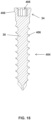
- the bone screws 30 each include the head portion 34 and a shank portion 404.
- the shank portion 404 includes threads 406 for driving into bone.
- the shank portion 404 is configured to be self-tapping.
- the head portion 34 includes a rotary drive structure, such as a socket 406, that receives a screwdriver such as a hexa-lobed screwdriver.
- the head portion 34 further includes a curved lower surface 408 for engaging a seating surface 410 (see FIG. 9B ) of the slider 18.
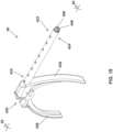
- the spacer removal instrument 50 includes a handle assembly 420 and a shaft assembly 422.
- the shaft assembly 422 includes a distal end portion 424 configured to engage one of the heads 40 of the spacers 36 and a proximal end portion 425 connected to the handle assembly 420.
- the handle assembly 420 includes a stationary grip 428 and a handle 426 pivotally connected to the stationary grip 428 by a pin 429.
- the shaft assembly 422 includes an outer sleeve 430 mounted to the stationary grip 428 and an inner shaft 432 connected to the handle 426.
- the inner shaft 432 includes a rim 440 having the one or more resilient fingers 400 mounted thereto.
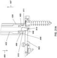
- the resilient fingers 400 are mounted to the inner shaft 432 with pins that extend through openings 441 (see FIG. 21A ) of the resilient fingers 411.
- the inner shaft 432 and the one or more resilient fingers 400 have an integral construction rather than being assembled.
- the inner shaft 432 also includes a cannula 442 for holding the spacers 36 in a line within the cannula 442 as the spacers 36 are removed one by one from the bone plate 12.
- the grip 428 may be movable and the handle 426 may be fixed or both the grip 428 and the handle 426 may be movable to operate the instrument 50.
- a method (not part of the claimed invention) is provided for removing a spacer 814 from a bone plate 802 of a bone plate system 800 (see FIG. 31 ) using the instrument 50.
- a user holds the instrument 50 so that the opening 446 of the inner shaft 432 is adjacent a head 815 of the spacer 814.
- the user advances the instrument 50 in direction 405 toward the bone plate 802 until the head 815 enters the opening 446 and the resilient fingers 400 snap below the head 815 of the spacer 814.
- the user pivots the grip 426 in direction 450 (see FIG. 20 ) while pressing the instrument 50 against the bone plate 802.
- the pivoting of the grip 426 causes the inner shaft 432 to shift in direction 447 relative to the outer sleeve 430 and engages the resilient fingers 400 with the underside of the head 815.
- a rim 449 of the outer sleeve 430 contacts the bone plate 802 and one of the sliders 808 therein.
- the user's moving of the handle 426 toward the stationary grip 428 causes the inner shaft 432 to pull the spacer 814 in direction 447 outward from the bone plate 802.
- the user releases the handle 426 and the handle 426 may be biased back toward its initial position by a spring of the instrument 50.
- the user positions the instrument 50 at a second spacer 814.
- the user may simply press the instrument 50 in direction 405 onto the second spacer 814 which causes the second spacer 814 to shift the first spacer 814 farther into the cannula 442 and beyond the resilient fingers 400 as shown in FIG. 21D .
- the instrument 50 is pressed in direction 405 until the resilient fingers 400 snap below the head 815 of the second spacer.
- the user pivots the handle 426 toward the stationary grip 428 which causes the inner shaft 432 to shift in direction 447, the outer sleeve to engage the bone plate 802/slider 808, and the inner shaft 432/resilient fingers 400 to pull the second spacer 814 out of the bone plate 802 as shown in FIGS. 21D and 21E .
- a bone plate system 600 includes a bone plate 602 and slider assemblies 604 that receive bone screws 606 and are shifted along throughbores 608 of the bone plate 602 by biasing assemblies 610 once spacers 612 of the bone plate system 600 have been removed.
- the slider assemblies 604 include sliders 604A, 604B and 604C.
- the slider assemblies 604A, 604B are identical to the slider assemblies 16 discussed above.
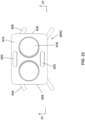
- the slider assembly 604C is different and includes a slider 614 having two throughbores 616 for receiving two bone screws 606.
- the slider assembly 604C includes the slider 614 and one or more resilient members, such as wires 620, 622.
- the wires 620, 622 each have end portions 624, 626 that extend outward from sides 628, 630 of the slider 614 and engage through apertures 632 of the bone plate 602.
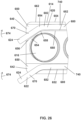
- the slider 614 has a curvature to compliment the curvature of an outer surface of a bone while minimizing interference with surrounding tissues.
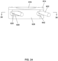
- the slider 614 includes a concave lower surface 634 and a convex upper surface 636. Due to the curvature of the slider 614, the wires 620, 622 have a complex curvature throughout the slider 614. More specifically and with reference to FIG. 24 , the slider 614 includes passageways 640, 642 and the wires 620, 622 extend upwardly and to the left (as seen in FIG. 24 ) into the passageways 640, 642 at the side 628.
- the passageways 640, 642 each include an outer enlarged portion 650 and a narrow intermediate portion 652.
- the slider 614 includes a wall 654 extending around each throughbore 616 and the wall 654 includes an angled surface 656, curved corner 658, and an intermediate support surface 660.
- the slider 614 includes a wall 662 opposite the wall 654 and across the passageway 640.
- the outer enlarged portion 650 of the passageway 640, 642 permits movement of an outer intermediate portion 670 of the wires 620, 622 as the wires 620, 622 straighten from a loaded configuration to an unloaded configuration and the outer intermediate portions 670 pivot in direction 674.
- the wires 620, 622 include intermediate portions 680 that contain a bend 740 (see FIG. 29 ) out of the page in FIG. 26 as well as inner intermediate portions 682 that are connected to the outer intermediate portions 670 by bends 684 generally in the plane of the cross section taken of FIG. 26 .
- the passageway 642 is shown and it will appreciated that the passageway 640 is similar in many respects. More specifically, the passageway 642 includes a first passageway portion 712 extending inward from side 628 and having an axis 700. The passageway 642 includes a second passageway portion 714 extending inward from the side 630 and having an axis 702 therein. There is an angle 704 between the axes 700, 702. The angle 704 forms a bend 740 (see FIG. 29 ) in the intermediate portion 680 of the wire 622 to provide enough material in a lower wall 706 of the slider 614 and accommodate the concave lower surface 634.
- the slider 614 includes an upper wall 708 having a through opening 710 therein that permits viewing of the wire 622.
- Through opening 710 may be formed during manufacture of the slider 614 by a machine tool that enters the passageway 642 from above and machines out material as needed. In other embodiments, the through opening 710 is not utilized such as if the slider 614 is produced using additive manufacturing.
- the lower wall 706 includes an inclined surface 716 in the first passage portion 712 to support one of the inner intermediate portions 682 of the wire 622 and an inclined surface 718 in the second passageway portion 714 to support the other inner intermediate portion 682.
- the upper wall 708 includes inclined surfaces 722, 724 which together with the lower inclined surfaces 716, 718 maintain the bend 740 in the intermediate portion 680 whether the wire 622 is in the loaded or unloaded configuration thereof.
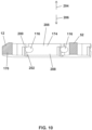
- FIG. 28 the wire 622 is shown removed from the slider 614 and is in the loaded configuration thereof.
- the outer intermediate portion 670 is at an angle 730 relative to the inner intermediate portion 682 and forms two bends 684 in the wire 622.
- FIG. 28 is a top plan view
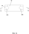
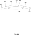
- FIG. 29 is a rear elevation view of the wire 622 in the loaded configuration thereof.
- the first passageway portion 712 and the second passageway portion 714 create the bend 740 in the intermediate portion 680 of the wire 622 to provide clearance for the concave lower surface 634 of the slider 714.
- the bend 740 positions the outer intermediate portions 670 at an angle 742 relative to one another.
- each wire 620, 622 has three bends including the two bends 684 and the bend 740.
- the bends 684 straighten out in a manner similar to the straightening of the bend 295 as one goes from FIG. 15 to FIG. 16 .
- the passageways 640, 642 maintain the bend 740 in the intermediate portions 680 of the wires 620, 622 because the inner intermediate portions 682 are constrained against movement unlike the outer intermediate portions 670.
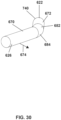
- the wire 622 is shown in a side elevational view to illustrate how each of the bends 684 orients the outer intermediate portion 670 thereof to extend transversely to the inner intermediate portions 682.
- the bend 740 provides the vertical component (as shown in FIG. 30 ) of the extent of both the outer intermediate portion 670 and the inner intermediate portion 672 of the wire 622.
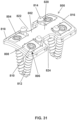
- the bone plate system 800 is similar in many respects to the bone plate system 10 discussed above.
- the bone plate system 800 includes a bone plate 802 having through openings 804 that receive slider assemblies 806.
- the slider assemblies 806 include sliders 808 having throughbores 810 that receive bone screws 812.
- the bone plate system 800 includes spacers 814 that may be removed from the bone plate 802 to permit the slider assemblies 806 to shift to unloaded positions which compresses bones connected to the bone screws 812.
- One difference between the bone plate system 800 and the bone plate system 10 discussed above is that the bone plate 802 has a dog bone-shaped configuration with enlarged end portions 816, 818 and a narrowed intermediate portion 820.
- the narrowed intermediate portion 820 forms notches 822, 824 on opposite sides of the bone plate 802.
- Each end portion 816, 818 includes two throughbores 810 to receive two slider assemblies 806.
- a bone plate 900 is provided that is similar in many respects to the bone plate 12 discussed above.
- the bone plate 900 may be utilized in the bone plate system 10 instead of the bone plate 12.
- the bone plate 900 includes through openings 902 configured to receive the slider assemblies 16.
- the bone plate 900 includes side walls 903 with apertures 904 for receiving end portions of the wires 20, 22 of the slider assemblies 16.
- each aperture 904 includes an angled surface 906 for supporting the associated wire 20, 22 and providing a more gradual bend of the wire 20, 22 when the sliders 18 are held in the loaded configuration in the through openings 902 by the spacers 36.
- the bone plate 12 has a varying thickness between upper and lower surfaces thereof including a thinner intermediate portion 910 between thicker side portions 912.
- the thinner intermediate portion 910 may include, for example, a generally concave surface portion.
- the lower surface 914 of the bone plate 900 may have a generally concave surface portion.
- the thinner intermediate portion 910 provides a reduced thickness along the midline of the plate which may improve interaction with surrounding tissues for some patients.
Landscapes
- Health & Medical Sciences (AREA)
- Orthopedic Medicine & Surgery (AREA)
- Surgery (AREA)
- Life Sciences & Earth Sciences (AREA)
- Heart & Thoracic Surgery (AREA)
- Nuclear Medicine, Radiotherapy & Molecular Imaging (AREA)
- Engineering & Computer Science (AREA)
- Biomedical Technology (AREA)
- Neurology (AREA)
- Medical Informatics (AREA)
- Molecular Biology (AREA)
- Animal Behavior & Ethology (AREA)
- General Health & Medical Sciences (AREA)
- Public Health (AREA)
- Veterinary Medicine (AREA)
- Surgical Instruments (AREA)
- Pivots And Pivotal Connections (AREA)
Claims (15)
- Knochenplattensystem (10), umfassend:eine Knochenplatte (12);mehrere langgestreckte Durchgangsöffnungen (14) der Knochenplatte (12), wobei jede langgestreckte Durchgangsöffnung (14) zwei einander über die Durchgangsöffnung (14) gegenüberliegende Endabschnitte (62, 64) aufweist;mehrere Knochenschrauben (30), die jeweils einen Kopfabschnitt (34) und einen Schaftabschnitt (404) aufweisen, wobei der Schaftabschnitt (404) dazu konfiguriert ist, in den Knochen getrieben zu werden;mehrere Schieber (18) in den langgestreckten Durchgangsöffnungen (14), die Durchgangsbohrungen (32) aufweisen, die zur Aufnahme der Kopfabschnitte (34) der Knochenschrauben (30) konfiguriert sind, wobei die Schieber (18) und die darin aufgenommenen Knochenschraubenkopfabschnitte (34) innerhalb der langgestreckten Durchgangsöffnungen (14) relativ zur Knochenplatte (12) verschiebbar sind;wenigstens ein elastisches Element, das dazu konfiguriert ist, eine Vorspannkraft auf den Schieber (18) auszuüben, um den Schieber (18) in Richtung zu einem Endabschnitt (64) einer entsprechenden Durchgangsöffnung (14) zu drängen; undwenigstens eine Betätigungsvorrichtung, die eine Eingriffsposition aufweist, in der die Betätigungsvorrichtung eine Verschiebung der Schieber (18) in Richtung zu dem einen Endabschnitt (64) der jeweiligen Durchgangsöffnungen (14) verhindert, und eine Freistellungsposition, in der die Betätigungsvorrichtung dem wenigstens einen elastischen Element ermöglicht, die Schieber (18) und die darin aufgenommenen Knochenschrauben (30) entlang der Durchgangsöffnungen (14) der starren Knochenplatte (12) und in Richtung zu dem einen Endabschnitt (64) der Durchgangsöffnungen (14) zu drängen.
- Knochenplattensystem (10) nach Anspruch 1, wobei die wenigstens eine Betätigungsvorrichtung in ihrer Eingriffsposition das wenigstens eine elastische Element in einer belasteten Konfiguration hält und jeden der Schieber (18) an einem gegenüberliegenden Endabschnitt (62) der jeweiligen Durchgangsöffnung (14) hält.
- Knochenplattensystem (10) nach Anspruch 1, wobei das wenigstens eine elastische Element umfasst:mehrere langgestreckte elastische Drähte (20, 22), die jeweils einem der Schieber (18) zugeordnet sind; odermehrere langgestreckte elastische Elemente, die jeweils ein Paar gegenüberliegender Endabschnitte (104, 106) und einen Zwischenabschnitt (107) zwischen den Endabschnitten (104, 106) aufweisen, wobei der Zwischenabschnitt (107) von einem der Schieber (18) gestützt wird und die Endabschnitte (104, 106) von der Knochenplatte (12) gestützt werden; odermehrere elastische Elemente, die sich jeweils zwischen einem der Schieber (18) und der Knochenplatte (12) erstrecken, wobei jedes elastische Element eine verformte Konfiguration aufweist, die einen gebogenen Abschnitt enthält, wenn sich die wenigstens eine Betätigungsvorrichtung in der Eingriffsposition befindet, wobei sich der gebogene Abschnitt in Richtung zu einer nicht verformten Konfiguration desselben strecken kann, wenn sich die wenigstens eine Betätigungsvorrichtung in der Freistellungsposition befindet; oderein Paar elastische Elemente, die an jedem der Schieber (18) befestigt sind, wobei jedes elastische Element ein Paar Abschnitte aufweist, die den Schieber (18) mit der Knochenplatte (12) verbinden.
- Knochenplattensystem (10) nach Anspruch 1, wobei die wenigstens eine Betätigungsvorrichtung mehrere Betätigungsvorrichtungen umfasst, die jeweils einen Kopfabschnitt aufweisen, der dazu konfiguriert ist, mit einem Instrument zum Entfernen der Betätigungsvorrichtung in Eingriff zu kommen, und einen Körperabschnitt, der zwischen einem der Schieber (18) und der Knochenplatte (12) gehalten wird, wenn sich die Betätigungsvorrichtung in der Eingriffsposition befindet.
- Knochenplattensystem (10) nach Anspruch 1, wobei die Knochenplatte (12) einen flachen Wandabschnitt (200, 202) aufweist, der sich entlang einer der Durchgangsöffnungen (14) erstreckt, und einer der Schieber (18) einen flachen Wandabschnitt (100, 102) aufweist, der dem flachen Wandabschnitt (200, 202) der Knochenplatte (12) zugewandt ist; und
die wenigstens eine Betätigungsvorrichtung ein Paar Abflachungen (54, 56) aufweist, die in Eingriff mit den flachen Wandabschnitten (200, 202) der Knochenplatte (12) und dem einen Schieber (18) stehen, wenn sich die Betätigungsvorrichtung in der Eingriffsposition befindet. - Knochenplattensystem (10) nach Anspruch 1, wobei wenigstens einer der Schieber (18) ein Paar Durchgangsbohrungen (32) aufweist, die so bemessen sind, dass sie Kopfabschnitte (34) eines Paares von Knochenschrauben (30) aufnehmen.
- Knochenplattensystem (10) nach Anspruch 1, wobei die Knochenplatte (12) eine einheitliche, einteilige Konstruktion aufweist.
- Knochenplattensystem (10) nach Anspruch 1, wobei die Schieber (18) starr sind und sich beim Einsetzen der Knochenankerkopfabschnitte (34) in die Durchgangsbohrungen (32) der Schieber (18) nicht verformen.
- Knochenplattensystem (10) nach Anspruch 1, wobei sich das wenigstens eine elastische Element in einer verformten Konfiguration befindet, wenn sich die wenigstens eine Betätigungsvorrichtung in der Eingriffsposition befindet, und eine Vorspannkraft gegen jeden der Schieber (18) ausübt, um die wenigstens eine Betätigungsvorrichtung zwischen den Schiebern (18) und der Knochenplatte (12) zu klemmen, und das wenigstens eine elastische Element in Richtung zu einer unverformten Konfiguration wechselt, wenn sich die wenigstens eine Betätigungsvorrichtung in der Freistellungsposition befindet.
- Knochenplattensystem (10) nach Anspruch 1, wobei sich in jeder der langgestreckten Durchgangsöffnungen (14) der Knochenplatte (12) ein einzelner Schieber (18) befindet.
- Knochenplattensystem (10) nach Anspruch 1, wobei das Knochenplattensystem (10) zur Befestigung eines Knochenpaares eingerichtet ist, wobei die mehreren langgestreckten Durchgangsöffnungen (14) ein Paar langgestreckter Durchgangsöffnungen (14) der Knochenplatte (12) sind;wobei die mehreren Knochenschrauben (30) ein Paar von Knochenschrauben (30) zum Befestigen der Knochenplatte (12) an dem Knochenpaar sind;wobei die mehreren Schieber (18) ein Paar von Schiebern (18) in den langgestreckten Durchgangsöffnungen (14) der Knochenplatte (12) sind, wobei jeder Schieber (18) eine Durchgangsbohrung (32) aufweist, die dazu konfiguriert ist, dem Schaftabschnitt (404) einer der Knochenschrauben (30) zu ermöglichen, durch die Durchgangsbohrung (32) und in einen Knochen getrieben zu werden, und dem Kopfabschnitt (34) zu ermöglichen, in der Durchgangsbohrung (32) zu sitzen;wobei die wenigstens eine Betätigungsvorrichtung dazu konfiguriert ist, zwischen den Schiebern (18) und der Knochenplatte (12) geklemmt zu werden;wobei das wenigstens eine elastische Element dazu konfiguriert ist, die Vorspannkraft auf die Schieber (18) auszuüben, um die Schieber (18) gegen die wenigstens eine Betätigungsvorrichtung zu drücken und die Schieber (18) zu veranlassen, die wenigstens eine Betätigungsvorrichtung zwischen den Schiebern (18) und der Knochenplatte (12) zu klemmen; undwobei die wenigstens eine Betätigungsvorrichtung aus der Klemmung zwischen den Schiebern (18) und der Knochenplatte (12) herausnehmbar ist, so dass die Vorspannkraft jeden Schieber (18) und die darin befindliche Knochenschraube (30) in Richtung zu dem anderen Schieber (18) und der anderen Knochenschraube (30) drängt, um die Knochen zusammenzudrücken.
- Knochenplattensystem (10) nach Anspruch 11, wobei das wenigstens eine elastische Element aufweist:wenigstens einen langgestreckten elastischen Draht (20, 22); oderein Paar langgestreckte elastische Drähte, die an jedem der Schieber befestigt sind und die Schieber mit der Knochenplatte verbinden; oderwenigstens eine Biegung, wenn die Betätigungsvorrichtung zwischen den Schiebern (18) und der Knochenplatte (12) geklemmt ist, wobei sich die wenigstens eine Biegung in Reaktion darauf streckt, dass die wenigstens eine Betätigungsvorrichtung aus der Klemmung zwischen den Schiebern (18) und der Knochenplatte (12) herausgenommen wird; oderwenigstens ein elastisches Element, das jedem der Schieber (18) zugeordnet ist.
- Knochenplattensystem (10) nach Anspruch 11, wobei jeder Schieber (18) gegenüberliegende Seiten und wenigstens einen Durchgang aufweist, der sich zwischen den Seiten erstreckt und so bemessen ist, dass sich das wenigstens eine elastische Element durch ihn hindurch erstrecken kann; und
wobei das wenigstens eine elastische Element ein Paar Abschnitte aufweist, die innerhalb des Durchgangs in Reaktion darauf schwenken, dass die wenigstens eine Betätigungsvorrichtung aus der Klemmung zwischen den Schiebern und der Knochenplatte herausgenommen wird, und der wenigstens eine Durchgang einen vergrößerten Abschnitt an jeder der Seiten aufweist, der die Schwenkbewegung der Abschnitte des elastischen Elements ermöglicht. - Knochenplattensystem (10) nach Anspruch 11, wobei die wenigstens eine Betätigungsvorrichtung mehrere Betätigungsvorrichtungen umfasst, die jeweils einen Kopfabschnitt aufweisen, der dazu konfiguriert ist, mit einem Instrument zum Entfernen der Betätigungsvorrichtung in Eingriff zu kommen, sowie einen Körperabschnitt zum Klemmen zwischen einem der Schieber und der Knochenplatte (12) und zum Verhindern einer Verschiebung des Schiebers (18) in Richtung zu dem anderen Schieber (18).
- Knochenplattensystem (10) nach Anspruch 11, wobei das wenigstens eine elastische Element superelastisches Nitinol enthält.
Applications Claiming Priority (2)
| Application Number | Priority Date | Filing Date | Title |
|---|---|---|---|
| US201862692464P | 2018-06-29 | 2018-06-29 | |
| PCT/US2019/039263 WO2020006089A1 (en) | 2018-06-29 | 2019-06-26 | Bone plate system |
Publications (4)
| Publication Number | Publication Date |
|---|---|
| EP3813699A1 EP3813699A1 (de) | 2021-05-05 |
| EP3813699A4 EP3813699A4 (de) | 2022-04-20 |
| EP3813699C0 EP3813699C0 (de) | 2025-05-07 |
| EP3813699B1 true EP3813699B1 (de) | 2025-05-07 |
Family
ID=68987231
Family Applications (1)
| Application Number | Title | Priority Date | Filing Date |
|---|---|---|---|
| EP19824755.3A Active EP3813699B1 (de) | 2018-06-29 | 2019-06-26 | Knochenplattensystem |
Country Status (8)
| Country | Link |
|---|---|
| US (1) | US11344346B2 (de) |
| EP (1) | EP3813699B1 (de) |
| JP (1) | JP7382976B2 (de) |
| CN (1) | CN112367937A (de) |
| AU (1) | AU2019295696B2 (de) |
| CA (1) | CA3104523C (de) |
| ES (1) | ES3035943T3 (de) |
| WO (1) | WO2020006089A1 (de) |
Families Citing this family (6)
| Publication number | Priority date | Publication date | Assignee | Title |
|---|---|---|---|---|
| US10123831B2 (en) | 2015-03-03 | 2018-11-13 | Pioneer Surgical Technology, Inc. | Bone compression device and method |
| US11877779B2 (en) | 2020-03-26 | 2024-01-23 | Xtant Medical Holdings, Inc. | Bone plate system |
| US11894682B2 (en) | 2020-05-15 | 2024-02-06 | Caterpillar Inc. | Methods and systems for off-grid load stabilization of energy distribution systems |
| US12290296B2 (en) * | 2020-07-02 | 2025-05-06 | Xieping DONG | Bone fixation system capable of gradually changing from rigid fixation to axial non-rigid fixation |
| CN111658116B (zh) * | 2020-07-02 | 2025-09-16 | 董谢平 | 可从坚强固定自动转化为弹性固定的接骨板 |
| EP4618868A1 (de) * | 2022-11-16 | 2025-09-24 | The Penn State Research Foundation | Nachgiebige knochenplatte zur frakturfixierung |
Family Cites Families (101)
| Publication number | Priority date | Publication date | Assignee | Title |
|---|---|---|---|---|
| US2580821A (en) | 1950-10-21 | 1952-01-01 | Nicola Toufick | Spring impactor bone plate |
| US3710789A (en) | 1970-12-04 | 1973-01-16 | Univ Minnesota | Method of repairing bone fractures with expanded metal |
| US3900025A (en) | 1974-04-24 | 1975-08-19 | Jr Walter P Barnes | Apparatus for distracting or compressing longitudinal bone segments |
| US3939828A (en) | 1974-09-09 | 1976-02-24 | Mohr Robert N | Method and clasp for internal osseous fixation |
| ZA80327B (en) | 1979-08-23 | 1981-09-30 | U Mennen | Internal fixation device for bone fractures |
| DE3808937A1 (de) | 1988-03-17 | 1989-10-05 | Fischer Artur Werke Gmbh | Verbindungselement zum verbinden und stabilisieren eines knochens im bereich einer fraktur |
| US5281226A (en) | 1989-03-31 | 1994-01-25 | Davydov Anatoly B | Missing portion of a tubular bone |
| US5026390A (en) | 1989-10-26 | 1991-06-25 | Brown Alan W | Surgical staple |
| CA1317173C (en) * | 1989-11-08 | 1993-05-04 | Amnon Foux | Plate for broken bone fixation |
| CN2143965Y (zh) * | 1992-02-15 | 1993-10-20 | 海军总医院 | 双曲齿座加压接骨钢板 |
| US5423816A (en) | 1993-07-29 | 1995-06-13 | Lin; Chih I. | Intervertebral locking device |
| US5458642A (en) | 1994-01-18 | 1995-10-17 | Beer; John C. | Synthetic intervertebral disc |
| SE9402130D0 (sv) | 1994-06-17 | 1994-06-17 | Sven Olerud | Anordning samt förfarande för plattfixation av ben |
| US5620443A (en) | 1995-01-25 | 1997-04-15 | Danek Medical, Inc. | Anterior screw-rod connector |
| US5634926A (en) | 1995-04-25 | 1997-06-03 | Jobe; Richard P. | Surgical bone fixation apparatus |
| US6364909B1 (en) | 1995-07-18 | 2002-04-02 | Iowa State University Research Foundation, Inc. | Method of restructuring bone |
| US5713900A (en) | 1996-05-31 | 1998-02-03 | Acromed Corporation | Apparatus for retaining bone portions in a desired spatial relationship |
| WO1998001076A1 (de) | 1996-07-09 | 1998-01-15 | Synthes Ag Chur | Vorrichtung für die knochenchirurgie |
| US5766218A (en) | 1996-10-01 | 1998-06-16 | Metamorphic Surgical Devices, Inc. | Surgical binding device and method of using same |
| US6533786B1 (en) * | 1999-10-13 | 2003-03-18 | Sdgi Holdings, Inc. | Anterior cervical plating system |
| US6136002A (en) | 1999-02-05 | 2000-10-24 | Industrial Technology Research Institute | Anterior spinal fixation system |
| WO2000062693A1 (en) | 1999-04-21 | 2000-10-26 | Eaves Felmont F Iii | Bone fracture fixation clip |
| US6059787A (en) | 1999-04-26 | 2000-05-09 | Allen; Drew | Compression bone staple apparatus and method |
| US6342055B1 (en) | 1999-04-29 | 2002-01-29 | Theken Surgical Llc | Bone fixation system |
| US6645207B2 (en) | 2000-05-08 | 2003-11-11 | Robert A. Dixon | Method and apparatus for dynamized spinal stabilization |
| WO2001089428A2 (en) | 2000-05-25 | 2001-11-29 | Neurortho Implants Design, Llc | Inter-vertebral disc prosthesis for rachis for an anterior surgery thereof |
| ES2264692T3 (es) * | 2000-05-31 | 2007-01-16 | Vese, Silvana | Dispositivos para fijar una placa osea. |
| ITRM20010123A1 (it) | 2001-03-09 | 2002-09-09 | Leonardo Bordi | Fissatore interno a fascia per fratture e protesi ossee. |
| US7862587B2 (en) * | 2004-02-27 | 2011-01-04 | Jackson Roger P | Dynamic stabilization assemblies, tool set and method |
| US20080147126A1 (en) * | 2001-10-18 | 2008-06-19 | Fxdevices, Llc | System and method for a cap used in the fixation of bone fractures |
| WO2003032848A2 (en) | 2001-10-19 | 2003-04-24 | Baylor College Of Medicine | Bone compression devices and systems and methods of contouring and using same |
| JP4332426B2 (ja) | 2001-10-23 | 2009-09-16 | ビーダーマン・モテーク・ゲゼルシャフト・ミット・ベシュレンクタ・ハフツング | 骨を固定するための装置、およびその装置用ねじ |
| US6695846B2 (en) | 2002-03-12 | 2004-02-24 | Spinal Innovations, Llc | Bone plate and screw retaining mechanism |
| US20040147928A1 (en) | 2002-10-30 | 2004-07-29 | Landry Michael E. | Spinal stabilization system using flexible members |
| US20040116931A1 (en) | 2002-12-17 | 2004-06-17 | Carlson Gregory D. | Vertebrae fixation device and method of use |
| US7914561B2 (en) | 2002-12-31 | 2011-03-29 | Depuy Spine, Inc. | Resilient bone plate and screw system allowing bi-directional assembly |
| US7291152B2 (en) | 2003-04-18 | 2007-11-06 | Abdou M Samy | Bone fixation system and method of implantation |
| US6986771B2 (en) | 2003-05-23 | 2006-01-17 | Globus Medical, Inc. | Spine stabilization system |
| US7763056B2 (en) | 2003-08-18 | 2010-07-27 | Dalton Brian E | Cervical compression plate assembly |
| US20050203513A1 (en) | 2003-09-24 | 2005-09-15 | Tae-Ahn Jahng | Spinal stabilization device |
| US7833256B2 (en) | 2004-04-16 | 2010-11-16 | Biedermann Motech Gmbh | Elastic element for the use in a stabilization device for bones and vertebrae and method for the manufacture of such elastic element |
| US20060058796A1 (en) | 2004-09-14 | 2006-03-16 | Hartdegen Vernon R | Compression brace |
| WO2006078989A2 (en) | 2005-01-21 | 2006-07-27 | Loubert Suddaby | Orthopedic fusion plate device having subsidence controlling features |
| US8740955B2 (en) * | 2005-02-15 | 2014-06-03 | Zimmer, Inc. | Bone screw with multiple thread profiles for far cortical locking and flexible engagement to a bone |
| WO2008024937A2 (en) | 2006-08-23 | 2008-02-28 | Pioneer Surgical Technology, Inc. | Minimally invasive surgical system |
| US7993380B2 (en) | 2005-03-31 | 2011-08-09 | Alphatel Spine, Inc. | Active compression orthopedic plate system and method for using the same |
| US7749256B2 (en) | 2005-04-05 | 2010-07-06 | Warsaw Orthopedic, Inc. | Ratcheting fixation plate |
| CN101262828B (zh) * | 2005-07-13 | 2011-06-15 | 精密医疗责任有限公司 | 具有可移动的锁紧元件的接骨板 |
| BRPI0520683A2 (pt) | 2005-11-16 | 2009-05-19 | Synthes Gmbh | dispositivo para fixação óssea com pelo menos um furo passante para recepção de um meio de fixação óssea |
| US8740903B2 (en) | 2006-02-09 | 2014-06-03 | DePuy Synthes Products, LLC | Method and apparatus for bone fracture fixation |
| JP2009540872A (ja) * | 2006-03-22 | 2009-11-26 | パイオニア サージカル テクノロジー インコーポレイテッド | ロートップ骨固定システム及びその使用方法 |
| US8257404B2 (en) | 2006-06-16 | 2012-09-04 | Hack Bradford H | Bone plate with dynamic compression |
| US8226693B2 (en) * | 2006-06-16 | 2012-07-24 | Reimels William J | Bone bridge providing dynamic compression on bone fractures |
| US20080147124A1 (en) | 2006-10-31 | 2008-06-19 | Haidukewych George J | Bone plate system with slidable compression holes |
| US20080147125A1 (en) * | 2006-12-12 | 2008-06-19 | Dennis Colleran | Active Settling Plate and Method of Use |
| FR2913876B1 (fr) | 2007-03-20 | 2009-06-05 | Memometal Technologies Soc Par | Dispositif d'osteosynthese |
| JP5197732B2 (ja) * | 2007-03-22 | 2013-05-15 | シンセス ゲゼルシャフト ミット ベシュレンクテル ハフツング | 骨プレート |
| US20080269753A1 (en) | 2007-04-26 | 2008-10-30 | Blue Fury Consulting, Llc | Dynamic cervical plate |
| US8043346B2 (en) | 2007-05-18 | 2011-10-25 | Custom Spine, Inc. | Anterior cervical plate with independent spring-loaded locking slides for each screw |
| GB2450247B (en) | 2007-06-15 | 2010-01-13 | Joel Gillard | Rib fixation with an intramedullary nail |
| US8623019B2 (en) * | 2007-07-03 | 2014-01-07 | Pioneer Surgical Technology, Inc. | Bone plate system |
| US8425513B2 (en) | 2008-03-24 | 2013-04-23 | Clavicle, Llc | Method and system for the intramedullary fixation of a fractured bone |
| DE102008002389B4 (de) | 2008-06-12 | 2013-05-16 | Medxpert Gmbh | Vorrichtung zur Osteosynthese sowie zur Fixierung und Stabilisierung von Röhrenknochen |
| CA2734065C (en) | 2008-08-15 | 2015-11-24 | Ao Technology Ag | Bone fixation device |
| US9775657B2 (en) | 2011-09-30 | 2017-10-03 | Acute Innovations Llc | Bone fixation system with opposed mounting portions |
| CN201353195Y (zh) * | 2009-01-14 | 2009-12-02 | 创生医疗器械(江苏)有限公司 | 可降解加压接骨螺钉 |
| WO2010105279A1 (en) | 2009-03-13 | 2010-09-16 | Harold Hess | Dynamic vertebral column plate system |
| US8574270B2 (en) | 2009-03-13 | 2013-11-05 | Spinal Simplicity Llc | Bone plate assembly with bone screw retention features |
| US9855082B2 (en) | 2009-05-12 | 2018-01-02 | DePuy Synthes Products, Inc. | Readjustable locking plate hole |
| FR2955480B1 (fr) | 2010-01-26 | 2012-01-06 | Christian Choux | Dispositif d'osteosynthese de la paroi thoracique |
| WO2011116377A1 (en) | 2010-03-19 | 2011-09-22 | Extremity Medical | Tabbed compression plate and method of use |
| US8758347B2 (en) | 2010-03-19 | 2014-06-24 | Nextremity Solutions, Inc. | Dynamic bone plate |
| AU2011270934B2 (en) | 2010-06-23 | 2014-09-11 | Zimmer, Inc | Flexible plate fixation of bone fractures |
| US8790379B2 (en) | 2010-06-23 | 2014-07-29 | Zimmer, Inc. | Flexible plate fixation of bone fractures |
| BR122014023771A2 (pt) * | 2010-09-30 | 2019-08-13 | Ethicon Endo-Surgery, Inc. | atuador de extremidade para uso em conexão com um instrumento cirúrgico e atuador de extremidade para fixação a um instrumento cirúrgico |
| CN101999927B (zh) | 2010-11-28 | 2012-07-25 | 孙德修 | 接骨板万向锁定加压装置 |
| US8728127B2 (en) | 2011-01-18 | 2014-05-20 | Spineworks, Llc | Bone plate incorporating a compression mechanism and associated surgical methods |
| US9005255B2 (en) | 2011-02-15 | 2015-04-14 | Orthohelix Surgical Designs, Inc. | Orthopedic compression plate |
| EP2713914A4 (de) | 2011-06-01 | 2014-12-17 | Alfred Health | Knochenschiene |
| CN102217972B (zh) * | 2011-06-09 | 2013-04-24 | 徐达强 | 应用于关节骨折的可量化扭力的组合型加压锁定装置 |
| EP2725997A4 (de) | 2011-06-29 | 2015-11-25 | Albany Medical College | Dynamisches wirbelsäulenplattensystem |
| WO2015168311A1 (en) | 2011-09-22 | 2015-11-05 | Mx Orthopedics, Corp | Controlling the unloading stress of nitinol devices and/or other shape memory material devices |
| US20160074082A1 (en) | 2011-10-20 | 2016-03-17 | Stryker Trauma Sa | Flexible locked plate fixation |
| US9579135B2 (en) | 2011-12-22 | 2017-02-28 | Fellowship of Orthopaedic Researchers, LLC | Plate and screw apparatus and methods thereof |
| US9241807B2 (en) | 2011-12-23 | 2016-01-26 | Pioneer Surgical Technology, Inc. | Systems and methods for inserting a spinal device |
| US9295508B2 (en) | 2012-02-03 | 2016-03-29 | Zimmer, Inc. | Bone plate for elastic osteosynthesis |
| US10485592B2 (en) | 2012-05-10 | 2019-11-26 | Spinal Simplicity, Llc | Locking fastener for use with dynamic bone fracture plates |
| US8974504B2 (en) | 2012-05-10 | 2015-03-10 | Spinal Simplicity Llc | Dynamic bone fracture plates |
| US8932335B2 (en) | 2012-08-31 | 2015-01-13 | Warsaw Orthopedic, Inc. | Retaining mechanism |
| US9788863B2 (en) | 2012-10-22 | 2017-10-17 | Globus Medical, Inc. | Posterior lumbar plate |
| US20160166296A9 (en) | 2012-10-22 | 2016-06-16 | Globus Medical, Inc. | Posterior Lumbar Plate |
| US20150289918A1 (en) | 2012-11-12 | 2015-10-15 | Flower Orthopedic Corporation | Sterile-Packaged Disposable Contouring Tool Systems for Medical Implants and Methods for Contouring Medical Implants |
| US9999454B2 (en) | 2013-12-05 | 2018-06-19 | A&E Advanced Closure Systems, Llc | Bone plate system and method |
| US9408647B2 (en) | 2014-02-27 | 2016-08-09 | Biomedical Enterprises, Inc. | Method and apparatus for use of a compressing plate |
| WO2015167920A1 (en) | 2014-04-30 | 2015-11-05 | DePuy Synthes Products, Inc. | Tensioning instrument and related bone fixation systems |
| CN104146759A (zh) * | 2014-08-08 | 2014-11-19 | 江苏百易得医疗科技有限公司 | 可透光骨科接骨板 |
| US9883897B2 (en) | 2014-09-25 | 2018-02-06 | Biomedical Enterprises, Inc. | Method and apparatus for a compressing plate |
| US10123831B2 (en) | 2015-03-03 | 2018-11-13 | Pioneer Surgical Technology, Inc. | Bone compression device and method |
| US10065773B2 (en) * | 2016-06-22 | 2018-09-04 | Liquistop Llc | Container lid and valve including a locking mechanism |
| EP3320867B1 (de) * | 2016-11-14 | 2021-08-04 | Biedermann Technologies GmbH & Co. KG | Modulare knochenplatte und element solch einer modularen knochenplatte |
| CN107468325A (zh) * | 2017-08-17 | 2017-12-15 | 冯建书 | 一种适用于微创手术的后踝解剖锁定钢板 |
-
2019
- 2019-06-26 JP JP2020573246A patent/JP7382976B2/ja active Active
- 2019-06-26 ES ES19824755T patent/ES3035943T3/es active Active
- 2019-06-26 AU AU2019295696A patent/AU2019295696B2/en active Active
- 2019-06-26 WO PCT/US2019/039263 patent/WO2020006089A1/en not_active Ceased
- 2019-06-26 EP EP19824755.3A patent/EP3813699B1/de active Active
- 2019-06-26 CN CN201980043312.1A patent/CN112367937A/zh active Pending
- 2019-06-26 CA CA3104523A patent/CA3104523C/en active Active
- 2019-06-27 US US16/454,949 patent/US11344346B2/en active Active
Also Published As
| Publication number | Publication date |
|---|---|
| WO2020006089A1 (en) | 2020-01-02 |
| JP7382976B2 (ja) | 2023-11-17 |
| JP2021528200A (ja) | 2021-10-21 |
| US20200000501A1 (en) | 2020-01-02 |
| US11344346B2 (en) | 2022-05-31 |
| EP3813699A1 (de) | 2021-05-05 |
| EP3813699A4 (de) | 2022-04-20 |
| EP3813699C0 (de) | 2025-05-07 |
| CA3104523A1 (en) | 2020-01-02 |
| ES3035943T3 (en) | 2025-09-11 |
| CA3104523C (en) | 2024-07-02 |
| CN112367937A (zh) | 2021-02-12 |
| AU2019295696B2 (en) | 2025-04-24 |
| AU2019295696A1 (en) | 2021-01-28 |
Similar Documents
| Publication | Publication Date | Title |
|---|---|---|
| EP3813699B1 (de) | Knochenplattensystem | |
| EP2627272B1 (de) | Externe fixationsklemmenanordnung mit einzelarretierung | |
| US7744632B2 (en) | Rod to rod connector | |
| EP2259737B1 (de) | Vorrichtung für vertebrale arthrodese | |
| EP1009311B1 (de) | Chirurgisches kabelsystem | |
| US6682533B1 (en) | Surgical cable system and method | |
| US6378289B1 (en) | Methods and apparatus for clamping surgical wires or cables | |
| US7452370B2 (en) | Apparatus for retaining a bone anchor in a bone plate and method for use thereof | |
| US20160143666A1 (en) | Polyaxial bone anchoring device | |
| WO2007041132A1 (en) | Manually actuated surgical clip applier | |
| WO2006047581A2 (en) | Bone plate system and methods | |
| JP2007307394A (ja) | 脊椎を固定するための装置 | |
| US20050137608A1 (en) | Cranial flap clamp instrument | |
| EP3375394B1 (de) | Kabelrückhalteeinsatz und knochenplattenanordnung mit solch einem kabelrückhalteeinsatz | |
| WO1993015880A2 (en) | Crimper | |
| WO2025235214A1 (en) | Adjustable medical/veterinary suture crimp tool |
Legal Events
| Date | Code | Title | Description |
|---|---|---|---|
| STAA | Information on the status of an ep patent application or granted ep patent |
Free format text: STATUS: THE INTERNATIONAL PUBLICATION HAS BEEN MADE |
|
| PUAI | Public reference made under article 153(3) epc to a published international application that has entered the european phase |
Free format text: ORIGINAL CODE: 0009012 |
|
| STAA | Information on the status of an ep patent application or granted ep patent |
Free format text: STATUS: REQUEST FOR EXAMINATION WAS MADE |
|
| 17P | Request for examination filed |
Effective date: 20210129 |
|
| AK | Designated contracting states |
Kind code of ref document: A1 Designated state(s): AL AT BE BG CH CY CZ DE DK EE ES FI FR GB GR HR HU IE IS IT LI LT LU LV MC MK MT NL NO PL PT RO RS SE SI SK SM TR |
|
| DAV | Request for validation of the european patent (deleted) | ||
| DAX | Request for extension of the european patent (deleted) | ||
| A4 | Supplementary search report drawn up and despatched |
Effective date: 20220317 |
|
| RIC1 | Information provided on ipc code assigned before grant |
Ipc: A61B 17/80 20060101ALI20220311BHEP Ipc: A61B 17/17 20060101ALI20220311BHEP Ipc: A61B 17/00 20060101AFI20220311BHEP |
|
| RAP1 | Party data changed (applicant data changed or rights of an application transferred) |
Owner name: PIONEER SURGICAL TECHNOLOGY, INC. |
|
| REG | Reference to a national code |
Ref country code: DE Ref legal event code: R079 Free format text: PREVIOUS MAIN CLASS: A61B0017800000 Ipc: A61B0017000000 Ref country code: DE Ref legal event code: R079 Ref document number: 602019069726 Country of ref document: DE Free format text: PREVIOUS MAIN CLASS: A61B0017800000 Ipc: A61B0017000000 |
|
| GRAP | Despatch of communication of intention to grant a patent |
Free format text: ORIGINAL CODE: EPIDOSNIGR1 |
|
| STAA | Information on the status of an ep patent application or granted ep patent |
Free format text: STATUS: GRANT OF PATENT IS INTENDED |
|
| RIC1 | Information provided on ipc code assigned before grant |
Ipc: A61B 17/80 20060101ALI20241111BHEP Ipc: A61B 17/17 20060101ALI20241111BHEP Ipc: A61B 17/00 20060101AFI20241111BHEP |
|
| INTG | Intention to grant announced |
Effective date: 20241129 |
|
| GRAS | Grant fee paid |
Free format text: ORIGINAL CODE: EPIDOSNIGR3 |
|
| GRAA | (expected) grant |
Free format text: ORIGINAL CODE: 0009210 |
|
| STAA | Information on the status of an ep patent application or granted ep patent |
Free format text: STATUS: THE PATENT HAS BEEN GRANTED |
|
| AK | Designated contracting states |
Kind code of ref document: B1 Designated state(s): AL AT BE BG CH CY CZ DE DK EE ES FI FR GB GR HR HU IE IS IT LI LT LU LV MC MK MT NL NO PL PT RO RS SE SI SK SM TR |
|
| REG | Reference to a national code |
Ref country code: GB Ref legal event code: FG4D |
|
| REG | Reference to a national code |
Ref country code: CH Ref legal event code: EP |
|
| REG | Reference to a national code |
Ref country code: DE Ref legal event code: R096 Ref document number: 602019069726 Country of ref document: DE |
|
| REG | Reference to a national code |
Ref country code: IE Ref legal event code: FG4D |
|
| PGFP | Annual fee paid to national office [announced via postgrant information from national office to epo] |
Ref country code: GB Payment date: 20250619 Year of fee payment: 7 |
|
| U01 | Request for unitary effect filed |
Effective date: 20250605 |
|
| RAP2 | Party data changed (patent owner data changed or rights of a patent transferred) |
Owner name: PARAGON 28, INC. |
|
| U07 | Unitary effect registered |
Designated state(s): AT BE BG DE DK EE FI FR IT LT LU LV MT NL PT RO SE SI Effective date: 20250711 |
|
| U20 | Renewal fee for the european patent with unitary effect paid |
Year of fee payment: 7 Effective date: 20250716 |
|
| REG | Reference to a national code |
Ref country code: GB Ref legal event code: 732E Free format text: REGISTERED BETWEEN 20250731 AND 20250806 |
|
| REG | Reference to a national code |
Ref country code: ES Ref legal event code: FG2A Ref document number: 3035943 Country of ref document: ES Kind code of ref document: T3 Effective date: 20250911 |
|
| PGFP | Annual fee paid to national office [announced via postgrant information from national office to epo] |
Ref country code: ES Payment date: 20250703 Year of fee payment: 7 |
|
| PG25 | Lapsed in a contracting state [announced via postgrant information from national office to epo] |
Ref country code: NO Free format text: LAPSE BECAUSE OF FAILURE TO SUBMIT A TRANSLATION OF THE DESCRIPTION OR TO PAY THE FEE WITHIN THE PRESCRIBED TIME-LIMIT Effective date: 20250807 Ref country code: GR Free format text: LAPSE BECAUSE OF FAILURE TO SUBMIT A TRANSLATION OF THE DESCRIPTION OR TO PAY THE FEE WITHIN THE PRESCRIBED TIME-LIMIT Effective date: 20250808 |
|
| PG25 | Lapsed in a contracting state [announced via postgrant information from national office to epo] |
Ref country code: PL Free format text: LAPSE BECAUSE OF FAILURE TO SUBMIT A TRANSLATION OF THE DESCRIPTION OR TO PAY THE FEE WITHIN THE PRESCRIBED TIME-LIMIT Effective date: 20250507 |
|
| PG25 | Lapsed in a contracting state [announced via postgrant information from national office to epo] |
Ref country code: HR Free format text: LAPSE BECAUSE OF FAILURE TO SUBMIT A TRANSLATION OF THE DESCRIPTION OR TO PAY THE FEE WITHIN THE PRESCRIBED TIME-LIMIT Effective date: 20250507 |
|
| PG25 | Lapsed in a contracting state [announced via postgrant information from national office to epo] |
Ref country code: RS Free format text: LAPSE BECAUSE OF FAILURE TO SUBMIT A TRANSLATION OF THE DESCRIPTION OR TO PAY THE FEE WITHIN THE PRESCRIBED TIME-LIMIT Effective date: 20250807 |
|
| PG25 | Lapsed in a contracting state [announced via postgrant information from national office to epo] |
Ref country code: IS Free format text: LAPSE BECAUSE OF FAILURE TO SUBMIT A TRANSLATION OF THE DESCRIPTION OR TO PAY THE FEE WITHIN THE PRESCRIBED TIME-LIMIT Effective date: 20250907 |
|
| PG25 | Lapsed in a contracting state [announced via postgrant information from national office to epo] |
Ref country code: SM Free format text: LAPSE BECAUSE OF FAILURE TO SUBMIT A TRANSLATION OF THE DESCRIPTION OR TO PAY THE FEE WITHIN THE PRESCRIBED TIME-LIMIT Effective date: 20250507 |
|
| PG25 | Lapsed in a contracting state [announced via postgrant information from national office to epo] |
Ref country code: CZ Free format text: LAPSE BECAUSE OF FAILURE TO SUBMIT A TRANSLATION OF THE DESCRIPTION OR TO PAY THE FEE WITHIN THE PRESCRIBED TIME-LIMIT Effective date: 20250507 |
|
| PG25 | Lapsed in a contracting state [announced via postgrant information from national office to epo] |
Ref country code: SK Free format text: LAPSE BECAUSE OF FAILURE TO SUBMIT A TRANSLATION OF THE DESCRIPTION OR TO PAY THE FEE WITHIN THE PRESCRIBED TIME-LIMIT Effective date: 20250507 |
|
| REG | Reference to a national code |
Ref country code: CH Ref legal event code: H13 Free format text: ST27 STATUS EVENT CODE: U-0-0-H10-H13 (AS PROVIDED BY THE NATIONAL OFFICE) Effective date: 20260127 |
|
| PG25 | Lapsed in a contracting state [announced via postgrant information from national office to epo] |
Ref country code: MC Free format text: LAPSE BECAUSE OF FAILURE TO SUBMIT A TRANSLATION OF THE DESCRIPTION OR TO PAY THE FEE WITHIN THE PRESCRIBED TIME-LIMIT Effective date: 20250507 |
|
| PLBE | No opposition filed within time limit |
Free format text: ORIGINAL CODE: 0009261 |
|
| STAA | Information on the status of an ep patent application or granted ep patent |
Free format text: STATUS: NO OPPOSITION FILED WITHIN TIME LIMIT |
|
| REG | Reference to a national code |
Ref country code: CH Ref legal event code: L10 Free format text: ST27 STATUS EVENT CODE: U-0-0-L10-L00 (AS PROVIDED BY THE NATIONAL OFFICE) Effective date: 20260318 |
|
| PG25 | Lapsed in a contracting state [announced via postgrant information from national office to epo] |
Ref country code: IE Free format text: LAPSE BECAUSE OF NON-PAYMENT OF DUE FEES Effective date: 20250626 |
|
| 26N | No opposition filed |
Effective date: 20260210 |
|
| PG25 | Lapsed in a contracting state [announced via postgrant information from national office to epo] |
Ref country code: CH Free format text: LAPSE BECAUSE OF NON-PAYMENT OF DUE FEES Effective date: 20250630 |