EP3812797B1 - Verarbeitungsvorrichtung, system, röntgenmessverfahren und programm - Google Patents
Verarbeitungsvorrichtung, system, röntgenmessverfahren und programm Download PDFInfo
- Publication number
- EP3812797B1 EP3812797B1 EP20201937.8A EP20201937A EP3812797B1 EP 3812797 B1 EP3812797 B1 EP 3812797B1 EP 20201937 A EP20201937 A EP 20201937A EP 3812797 B1 EP3812797 B1 EP 3812797B1
- Authority
- EP
- European Patent Office
- Prior art keywords
- pulse signal
- time constant
- time
- exposure
- pulse
- Prior art date
- Legal status (The legal status is an assumption and is not a legal conclusion. Google has not performed a legal analysis and makes no representation as to the accuracy of the status listed.)
- Active
Links
Images


Classifications
-
- G—PHYSICS
- G01—MEASURING; TESTING
- G01T—MEASUREMENT OF NUCLEAR OR X-RADIATION
- G01T1/00—Measuring X-radiation, gamma radiation, corpuscular radiation, or cosmic radiation
- G01T1/16—Measuring radiation intensity
- G01T1/18—Measuring radiation intensity with counting-tube arrangements, e.g. with Geiger counters
-
- G—PHYSICS
- G01—MEASURING; TESTING
- G01T—MEASUREMENT OF NUCLEAR OR X-RADIATION
- G01T1/00—Measuring X-radiation, gamma radiation, corpuscular radiation, or cosmic radiation
- G01T1/16—Measuring radiation intensity
- G01T1/24—Measuring radiation intensity with semiconductor detectors
- G01T1/247—Detector read-out circuitry
-
- G—PHYSICS
- G01—MEASURING; TESTING
- G01T—MEASUREMENT OF NUCLEAR OR X-RADIATION
- G01T1/00—Measuring X-radiation, gamma radiation, corpuscular radiation, or cosmic radiation
- G01T1/16—Measuring radiation intensity
- G01T1/161—Applications in the field of nuclear medicine, e.g. in vivo counting
- G01T1/164—Scintigraphy
- G01T1/166—Scintigraphy involving relative movement between detector and subject
- G01T1/1663—Processing methods of scan data, e.g. involving contrast enhancement, background reduction, smoothing, motion correction, dual radio-isotope scanning, computer processing ; Ancillary equipment
-
- G—PHYSICS
- G01—MEASURING; TESTING
- G01T—MEASUREMENT OF NUCLEAR OR X-RADIATION
- G01T1/00—Measuring X-radiation, gamma radiation, corpuscular radiation, or cosmic radiation
- G01T1/16—Measuring radiation intensity
- G01T1/17—Circuit arrangements not adapted to a particular type of detector
- G01T1/171—Compensation of dead-time counting losses
-
- G—PHYSICS
- G01—MEASURING; TESTING
- G01T—MEASUREMENT OF NUCLEAR OR X-RADIATION
- G01T1/00—Measuring X-radiation, gamma radiation, corpuscular radiation, or cosmic radiation
- G01T1/16—Measuring radiation intensity
- G01T1/24—Measuring radiation intensity with semiconductor detectors
Definitions
- the present invention relates to a processing apparatus with a photon-counting type semiconductor detector, and to a system, an X-ray measurement method and a program thereof.
- the photon-counting type semiconductor detector used for a radiation measurement measures an intensity of X-rays by counting the number of times when an intensity of a pulse signal detected in a predetermined time exceeds a threshold, as the number of pulse signals. However, when the next pulse signal is generated in a situation where the intensity of the pulse signal exceeds the threshold, the pulse signal cannot be counted, and thus count loss thereof occurs. When the intensity of X-rays is too high, the count loss occurs frequently, and the measured intensity of X-rays is consequently estimated to be lower than the actual intensity of X-rays.
- a method of correcting the measured count value has been investigated as a method of reducing influence of count loss like these (for example, Patent Document 1). Further, a method of counting pulses in such a manner that the count value approaches a true count during measurement is taken into consideration (for example, Patent Document 2).
- Patent Document 1 discloses a radiation measuring apparatus comprising a wave height discriminator 3 that outputs a digital pulse signal when an analog pulse signal output from a radiation detector 1 satisfies a predetermined condition and a signal channel wave height analyzer 4.
- the radiation measuring apparatus disclosed in Patent Document 1 counts digital pulse signals output from respective a first counter 5 and a second counter 6 to output count values M and P, and a calculator 7 correcting count loss and erroneous counting, referring to count loss correction tables 81 and 82 stored in a memory 8, with respect to count rates m and p obtained from count values M and P.
- Each of the correction tables finds resolution time t1 of pile-up and proximity time t2 during which the erroneous counting occurs, by making a double pulse be proximate with an experimentally generated pseudo signal pulse, to determine a primary correction count rate n and a secondary correction count rate (n - q).
- a method for photon counting imaging with high-rate counting performance improved by applying an instant retrigger capability provided with adjustable dead time in cells of a detector array, and an apparatus thereof, are disclosed in the Patent document 2. That is, as long as a signal pulse initially exceeds a threshold and subsequently exceeds the threshold, the method and the apparatus disclosed in Patent Document 2 reduce influence of the count loss by counting the number of dead time intervals of a predetermined width included in a time exceeding the threshold of the signal pulse and regarding the value as the number of photons arrived in a time higher than the threshold of the signal pulse.
- Patent Document 3 a correction technique is known capable of determining a correct input photon count rate based on a measured output photon count rate.
- the technique is based on identifying the correct input photon count rate from multiple candidate input photon count rates using a map.
- the technique further comprises reconstructing the output signal based on the corrected input photon count rate.
- the correction table performs correction by making a double pulse be proximate with the experimentally generated pseudo signal pulse to find the resolution time t1 of pile-up and the proximity time t2 during when the erroneous counting occurs, and thus accuracy of the correction becomes insufficient when the count rate is increased to such an extent that proximity of three or more pulses occurs frequently.
- the dead time is constant with respect to increase of the count rate, and thus accuracy of the correction becomes insufficient with increase of the count rate.
- the present invention is made in view of such a situation, and it is an object to provide a processing apparatus capable of reducing influence of count loss even on a higher count rate that has not been able to be covered by a conventional method, and to provide a system, an X-ray measurement method and a program thereof.
- the pulse detection ratio corresponds to the ratio of a total time during which the pulse signal is detected, to a total time of the exposure. In this manner, the pulse detection ratio can be easily calculated using a detector that is capable of exposing in a short period and in a short unit time.
- the apparent time constant corresponds to the time constant of the pulse signal when the pulse detection ratio is zero. In this manner, there is no influence on count loss when there is no overlapping of pulses with respect to the exposure, and thus the model becomes realistic.
- the apparent time constant is the product of the true time constant and a constant smaller than 1 when the pulse detection ratio is 1. In this manner, the count can be calculated even with respect to the maximum measurable output according to the model.
- the processing apparatus is the processing apparatus, wherein the storage section is configured to store the time constant of the pulse signal, and when using the model, the calculation section is configured to read out and use the stored time constant. In such a manner, the time constant can be read out and used when calculating the count value.
- the system according to the present invention is a system comprising a semiconductor detector, and the processing apparatus according to any one of the above-described (1) to (2). In this manner, the count value can be calculated with the processing apparatus, using the output value obtained from the semiconductor detector.
- the system according to the present invention is the system, wherein the exposure is performed in a shorter time than the time constant of the pulse signal with the semiconductor detector. In this manner, a physical phenomenon can be observed at high time resolution. Further, it is not possible to detect three or more pulses at one exposure, and thus load of readout thereof can be reduced. Further, the readout of the output value becomes sufficient in a 2-bit mode, and thus the readout time can be shortened.
- the count value is corrected with assuming that the pulse signal is counted in a time obtained by summing the time constant of the pulse signal and the exposure time ⁇ t for a frame , in the calculation of the count value. In this manner, the count value detected in a substantial exposure time can be obtained.
- the X-ray measurement method is an X-ray measurement method comprising the steps of reading an output value obtained by counting a pulse signal of incident X-rays by a photon-counting type semiconductor detector; and calculating a count value based on the output value that has been read out, wherein a model in which an apparent time constant of the pulse signal monotonously decreases against increase in pulse detection ratio is used in the step of calculating the count value, wherein the pulse detection ratio corresponds to a ratio of a total time during which the pulse signal is detected to a total time of an exposure, and the apparent time constant corresponds to the time constant of the pulse signal when the pulse detection ratio is zero, and wherein the apparent time constant is a product of the time constant of the pulse signal and a constant smaller than 1 when the pulse detection ratio is 1, and the time constant of the pulse signal is a time during which an intensity of a single pulse signal exceeds a threshold.
- the pulse detection ratio corresponds to a ratio of a total time during which the pulse signal is detected to a total time of an
- the program according to the present invention is a program causing a computer to execute the processes of reading an output value obtained by counting a pulse signal of incident X-rays by a photon-counting type semiconductor detector; and calculating a count value based on the output value that has been read out, wherein a model in which an apparent time constant of the pulse signal monotonously decreases against increase in pulse detection ratio with o exposure time as a time unit is used in the processing of calculating the count value, wherein the pulse detection ratio corresponds to a ratio of a total time during which the pulse signal is detected to a total time of an exposure, and the apparent time constant corresponds to the time constant of the pulse signal when the pulse detection ratio is zero, and wherein the apparent time constant is a product of the time constant of the pulse signal and a constant smaller than 1 when the pulse detection ratio is 1, and the time constant of the pulse signal is a time during which an intensity of a single pulse signal exceeds a threshold.
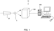
- FIG. 1 is a schematic diagram showing an example of a configuration of an X-ray detection system 10.
- the X-ray detection system 10 comprises an X-ray source 20, a sample S, an X-ray detector 100 and a processing apparatus 200.
- the X-ray source 20 generates X-rays by making electron flux radiated from a filament, which is a cathode, collide with a rotor target, which is an anticathode.
- Metal such as Mo or Cu, for example, is provided on an outer-peripheral face of the rotor target.
- X-rays including MoK ⁇ . rays (a wavelength of 0.711 ⁇ ), which are characteristic rays, are radiated.
- X-rays including CuK ⁇ rays (a wavelength of 1.542 ⁇ ), which are characteristic rays, are radiated.
- X-rays radiated from the X-ray source 20 are so-called point-focus X-ray beams.
- a sample S is supported by a sample support apparatus.
- the X-ray detector 100 detects, for example, X-rays such as X-rays diffracted by the sample S.
- the processing apparatus 200 processes the detected output value to calculate the count value. Details of the X-ray detector 100 and the processing apparatus 200 are mentioned below.
- the count value is calculated by using a model in which an apparent time constant of a pulse signal monotonously decreases against increase in pulse detection ratio with respect to exposure.
- this step is basically carried out inside the processing apparatus 200, but may also be performed inside the X-ray detector 100.
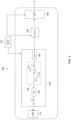
- FIG. 2 is a schematic diagram showing a configuration of an X-ray detector 100.
- the X-ray detector 100 that is a photon-counting type semiconductor detector has a two-dimensional data buffer function.
- the X-ray detector 100 detects X-rays, and transfers the detection data outside for every frame.
- the X-ray detector 100 may be a one-dimensional detector or a zero-dimensional detector.
- the X-ray detector 100 comprises a sensor 110, a readout circuit 120, a memory 150, a transfer circuit 160, and a control circuit 170.
- a configuration for one sensor 110 is shown for convenience, but the X-ray detector 100 is basically provided with a plurality of sensors.
- the readout circuit 120 provided with a gate 125, a detection circuit 130 and a counter 140 has a readout function.
- the sensor 110 generates pulses when X-ray particles are detected by exposure.
- the sensor 110 can detect the intensity of an X-ray flux incident on a receiving surface as surface information.
- the gate 125 makes pulses pass through the detection circuit 130 only for a duration of gate open time.
- open time of the gate 125 is called an exposure time ⁇ t. Opening/closing of the gate 125 is carried out by an electronic shutter.
- the exposure time ⁇ t is shortened, the time resolution is increased and more accurate measurement is able to be conducted, and thus an exposure time ⁇ t is preferable to be shorter.
- the exposure time ⁇ t is made to be shorter than the time constant ⁇ of the below-mentioned pulse signal, it is not possible to detect three or more pulses at one exposure, and thus load of readout thereof is reduced, which is preferred.
- its lower limit is set by the limit of a hardware function, but for example, the lower limit can be lowered by increasing a clock frequency, by making an instruction system of the gate control set a system different from the other controls to perform instruction with 1-bit, by multiplying a clock by a multiple of n (for example, 10 times) only for the gate control inside CPU, or the like.
- the detection circuit 130 determines whether or not the pulse is higher than a threshold, and transmits it to the counter 140 as a voltage signal when it is higher.
- the counter 140 can count the transmitted voltage signal as the number of pulses, and output it as an output value.
- the memory 150 reads out the output value counted by the counter 140 from the counter 140 to store it.
- the readout timing is basically preferred to be immediately after closing the gate 125, but the readout after a waiting time is also possible.
- the memory 150 converts the read-out unordered data into a real space arrangement, and makes it possible to transfer the data to a rear stage. Further, the memory 150 stores the total time of exposure, or the number of times of exposure.
- a plurality of detection circuits may be present for one sensor.
- a counter is presented for each detection circuit.
- a threshold used for determining a pulse can also be made to be different therefrom for each detection circuit.
- the memory there may be a plurality of switchable memories for writing, for one sensor.
- a gate can be opened to perform exposure even while reading out one memory, and thus it is possible to raise a duty ratio.
- a plurality of memories may be independently provided for each of the sensors, and the plurality of memories may be shared. For example, it is enough that two memories are provided for two sensors, and the two memories are present to be able to be switched for writing from each sensor.
- the transfer circuit 160 transfers the output value stored in the memory 150, and the total time of exposure or the number of times of exposure to the processing apparatus 200.
- the control circuit 170 makes the memory 150 store the total time of the exposure or the number of times of the exposure. Further, the control circuit 170 controls opening/closing of the gate 125, controls readout and storage of the output value, and controls transfer of the stored output value, and the total time of the exposure or the number of times of the exposure to the processing apparatus 200.
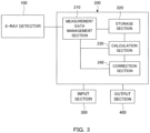
- FIG. 3 is a block diagram showing a configuration of a processing apparatus 200.
- the processing apparatus 200 comprising a measurement data management section 210, a storage section 220, a calculation section 230 and a correction section 240, calculates a count value or a count rate, based on an output value of X-rays detected by the X-ray detector 100, and the total time of exposure or the number of times of exposure.
- the measurement data management section 210 manages data handled in the storage section 220, the calculation section 230, and the correction section 240.
- the measurement data management section 210 receives the output value stored in the memory 150 inside the X-ray detector 100, and the total time of the exposure or the number of times of the exposure through the transfer circuit 160, and makes the storage section 220 store them.
- the storage section 220 stores the received output value, and the total time of exposure or the number of times of exposure. Further, the storage section 220 stores the count value or the count rate calculated based on the output value, and the total time of the exposure or the number of times of the exposure. Further, the storage section 220 stores the total time of exposure that is corrected by the correction section 240. Further, the storage section 220 stores the time constant of a pulse signal.
- the time constant read out from the storage 220 is used for calculating the count value and for setting the exposure time.
- the time constant changes its value depending on a setting value such as a threshold or the like, and thus it is applicable for any processing by storing a table form or the like in advance.
- the table is stored on the side of X-ray detector 100 and is read out.
- the calculation section 230 calculates the count value or the count rate based on the total output value and the time of exposure. At this time, used is a model in which an apparent time constant of a pulse signal monotonously decreases against increase in pulse detection ratio with respect to exposure. Details of the model are mentioned below. Further, the pulse detection ratio can be a value corresponding to a rate of a total time during which the pulse signal is detected with respect to exposure, to a total time of the exposure. The corresponding value means that the total time during which the pulse signal is detected with respect to the exposure can be replaced by the output value, and the total time of exposure can be replaced by the number of times of exposure or the corrected total time of exposure.
- the correction section 240 corrects the total time of exposure. Correction of the total time of exposure may be performed in such a manner that an exposure time for one exposure, for example, is set as a time obtained by adding a time constant ⁇ of a pulse signal and a unit time of exposure (exposure time ⁇ t) to calculate the total time of exposure. In this manner, the count value detected in a substantial exposure time can be obtained.
- the processing apparatus 200 is, for example, a personal computer.
- the personal computer is provided with, for example, CPU for controlling calculation, a memory for storing data, a system software stored in a predetermined region inside the memory, and an application program software stored in the other predetermined region inside the memory, and so forth.
- a keyboard or the like as an input section 300 that receives an input of a user is connected to the processing apparatus 200.
- an output section 400 such as a display, a printer or the like is connected to the processing apparatus 200.
- the output section 400 outputs the count value and so forth according to an instruction from the processing apparatus 200.
- the time constant ⁇ of a pulse signal means a time during which an intensity of a single pulse signal exceeds a threshold.
- the time constant ⁇ depends on an ROIC circuit.
- a time constant ⁇ of the original pulse signal is able to be used for setting an exposure condition. Further, this is also able to be used for the correction formula used when calculating the count value.
- the measurement method of the time constant is mentioned below as EXAMPLE.
- FIG. 4 is a schematic diagram showing count timing of a pulse according to an X-ray measurement method of the present invention.
- Each of t1 to t10 in FIG. 4 indicates an exposure time ⁇ t during which the gate is opened.
- 1 is added for the count when the pulse intensity exceeds a threshold in the interval.
- 1 is added for the count in the same way.
- signal height that exceeded a threshold temporarily falls below the threshold, and then exceeds the threshold again, during the exposure time ⁇ t, 2 is added for the count. The same applies to the cases of more than that.
- each of intervals between the exposure times may not be an equal interval.
- an exposure time ⁇ t is set to be shorter than a time constant ⁇ .
- the exposure time ⁇ t is set to be shorter than the time constant ⁇ , an event in which signal height that exceeded a threshold temporarily falls below a threshold, and then exceeds the threshold again, during the exposure time ⁇ t, appears one time or less. That is, the count during the exposure time ⁇ t becomes 2 or less. Further, when the exposure time ⁇ t is made to be sufficiently short, a V-shaped interval in the decrease/increase of pulse intensity cannot be recognized, and thus the count counted during the exposure time ⁇ t becomes 1 or less.
- the number of pulses counted in a unit exposure time becomes small by shortening the exposure time ⁇ t, thereby reducing the error count.
- the exposure time ⁇ t is made to be shorter than the time constant ⁇ of a pulse signal, detecting three pulses or more at one exposure can be avoided, and thus a transfer information amount can be set to 2 bits or less. Therefore, the readout time can be shortened.
- the count value when using an X-ray count value for analysis or the like, it is necessary to have the count value to a degree at which influence of statistical fluctuation is negligible. For example, in order to obtain a relative standard deviation of 1%, it is necessary to count 10,000 counts. In order to make the number of counting times of pulse signal per exposure time ⁇ t be any of 0, 1 and 2, it is preferred that the number of times of exposure is set in such a manner that a count of a pulse signal per total time of exposure statistically is a significance value by repeating the exposure with 10,000 to 30,000 counts as an achievement reference.
- a higher count region for example, a region of 10 Mcps or more is considerably affected by count loss.
- the processing at the rear stage performs correction for approaching the number of original pulses by correcting the influence of count loss.
- the counting result obtained by a counting method of a pulse signal according to the present invention as described above is used as an output value, but each of the results obtained by a method of counting Rising Edge (mentioned below) or a method of retriggering a time-trigger on a circuit of a detector may be used as an output value.
- the total time obtained by detecting the pulse signal is read out as an output value to calculate the count value of original pulses based on the output value that has been read out.
- the total time (output value) obtained by detecting the pulse signal may be used by directly reading out a time during which the pulse signal exceeds the threshold, or be estimated based on the total counts of the pulse signal.
- a model in which an apparent time constant of the pulse signal monotonously decreases against increase in pulse detection ratio with respect to exposure is used in the calculation of the count value.
- Pulse signals are overlapped when X-rays continuously reach a sensor, and a time during which signal height exceeds a threshold becomes long when height of the overlapped pulse signals exceeds the threshold.
- the time during which the threshold is exceeded becomes shorter than a value obtained by multiplying a time constant ⁇ by the number of pulses by an amount of overlapping the pulses. For example, even when two pulses are overlapped, the time during which the threshold is exceeded is shorter than two times of ⁇ , and even when three pulses are overlapped, it is shorter than three times of ⁇ .
- a value obtained by converting time during which a threshold is exceeded into time per one pulse signal is referred to as an apparent time constant ⁇ a of the pulse signal.
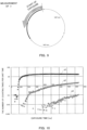
- FIG. 5 is a graph showing a pulse height when pulses are overlapped. As shown in FIG. 5 , when the number of overlapped pulse signals (N) per time (T up ) during which the pulses are detected increases, the apparent time constant ⁇ a gradually becomes shorter.
- Such a tendency is associated with the probability of pulse signals overlapping.
- the pulse detection ratio (count rate) increases, the number (N) of pulse signals increases, and the probability of pulse signals overlapping also rises. That is, it is possible to calculate the apparent time constant ⁇ a from the probability without discriminating how many signals are overlapped.
- a time per one pulse signal (apparent time constant ⁇ a ) gradually becomes shorter than a time constant ⁇ as the pulse detection ratio (count rate) increases. That is, the apparent time constant ⁇ a can be represented by the product of a time constant ⁇ and a monotonous decreasing function f of a count rate.
- a true count value (N) can be calculated from the relationship between a time T up during which signal height exceeds a threshold, and an apparent time constant ⁇ a with respect to a pulse detection ratio (count rate).
- a model in which the count value and the count rate as described above are calculated needs to have the following conditions.
- Each of formulae by which the count value prepared by the model is calculated represents dimensionless quantity.
- a value obtained by dividing the count value by the total time of exposure is the count rate.
- Formula (2) in which the count value N as shown in the following example is calculated can be used as a model.
- N represents a calculated count value
- ⁇ represents a time constant of a pulse signal
- T up represents a total time during which the pulse signal is detected with respect to exposure
- T tot represents the total time of exposure.
- ⁇ ⁇ f (T up , T tot ) represents the apparent time constant of the pulse signal.
- the f(T up , T tot ) becomes 1 when T up is 0, and monotonously decreases when T up /T tot increases in the range where T up /T tot is larger than 0 and smaller than 1.
- the f(T up , T tot ) approaches 0 when T up /T tot approaches 1, but may become a constant larger than 0 and smaller than 1.
- T tot T up T tot ⁇ ⁇ ⁇ f T up T tot
- the count rate n shown in Formula (3) is obtained by dividing the count value N shown in Formula (1) by the total time T tot of exposure. It is called monotonous decrease that the function value f(T up /T tot ) always decreases as the argument T up /T tot increases.
- the f(T up /T tot ) may be a monotonous decreasing function having such a property.
- the f(T up /T tot ) may be a n-th order function or an exponential function, thereby being irrespective of a kind of function.
- the following Formula (4) is used as a monotonous decreasing function f(T up , T tot ) in the following EXAMPLE.
- This function becomes a monotonous decreasing function by determining k in the range of 0 ⁇ k ⁇ 1.
- the count rate can be corrected to infinity theoretically by performing experiments as well as a simulation, and further determining an optimum constant m with a count rate range and a system.
- the count rate n in this case is given as shown in Formula (5).
- f Tup / Ttot 1 ⁇ k ⁇ T up T tot m
- n T up T tot ⁇ ⁇ ⁇ 1 ⁇ k ⁇ T up T tot m
- the time constant ⁇ changes its value depending on not only a detection circuit but also a pixel setting value.
- updating should be carried out depending on the corresponding detector or measurement condition.
- the value stored as a table form corresponding to the pixel setting value is read out and used by changing the condition to measure the time constant ⁇ .
- the time during which the pulse signal is detected that is, the time during which the pulse signal exceeds the threshold is difficult to be directly read out by a detector according to the embodiment, and thus the total time T up during which the pulse signal is detected with respect to exposure can be estimated and be set as an output value.
- the time constant ⁇ is constant, and thus a value obtained by multiplying the time constant ⁇ by the number of times of the dead time can be estimated as T up.
- a value obtained by multiplying the exposure time ⁇ t by the total number of counts of pulse signal is set as T up .
- the total time T tot of exposure becomes a value obtained by multiplying the exposure time ⁇ t by the number of times of exposure.
- the pulse detection ratio (T up /T tot ) corresponds to a ratio of the number of times of exposure to the total number of counts of pulse signal.
- the total time T up during which the pulse signal is detected with respect to exposure is represented by the product of the exposure time ⁇ t and the number of counts
- the total time T tot of exposure is represented by the product of the exposure time ⁇ t and the number of times of exposure (the number of frames).
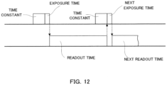
- FIG. 6 is a schematic diagram showing the relationship between the exposure time ⁇ t and the time constant ⁇ . The event of being counted within the exposure time ⁇ t is to be from the pulse generated earlier by an amount equivalent to the time constant ⁇ with respect to the exposure time ⁇ t to the pulse generated just before the end of the exposure time ⁇ t, as shown in FIG. 6 .
- the event of being counted within the exposure time ⁇ t is an event generated during (exposure time ⁇ t) + (time constant ⁇ ). Accordingly, there are some cases where the correction needs to be made by taking this effect into account, when integrating and outputting a plurality of acquired images, or the like.
- exposure is repeated multiple times without counting at a timing when the pulse upwardly passes through a threshold, and the count value is calculated using a model in which an apparent time constant of the pulse signal monotonously decreases against increase in pulse detection ratio with respect to exposure, based on the output value and the pulse detection ratio that are obtained via a number of sampling results.
- sampling it is carried out to determine whether or not the pulse exceeds a threshold during the exposure time ⁇ t shorter than the time constant ⁇ , until statistically becoming a significance number. In this manner, reduced can be influence of count loss even on a higher count rate that has not been able to be covered by a conventional method and correction thereof.
- the time constant ⁇ of an X-ray detector according to EXAMPLE was measured by utilizing a train bunch of Spring-8 provided with experimental facilities and various auxiliary facilities for utilizing a series of accelerators with which electrons are accelerated and stored, and radiation generated therein.
- An X-ray detector is assembled as part of a radiation detector of Spring-8 to conduct the following measurements.
- an electron beam generated from an electron gun is accelerated to 1 GeV with a linear accelerator, and is subsequently introduced into a synchrotron to be accelerated to 8 GeV.
- This electron beam is introduced into a storage ring, and radiation is generated by a deflection electromagnet or an insertion beam source while maintaining an energy of 8 GeV.
- the generated radiation is introduced into an experimental station provided inside and outside a storage ring house through a beam line.
- the electron beam is not continuously present inside the storage ring, but is present as an aggregate which is referred to as bunch.
- FIG. 7 is a diagram showing an example of a filling pattern inside a storage ring.
- FIG. 8 is a diagram showing the detection current of bunch with respect to time. Specifically, a filling pattern of 2018A (first half of 2018) several bunch operation mode (E mode) of Spring-8 is shown. A single bunch SB1 as a bunch of dotted electrons and a train bunch TB1 as a linearly successive bunch of electrons appear in the filling pattern shown in FIG. 7 .
- the bunch flying interval in this operation mode is 165.2 nsec, and as shown in FIG. 8 , the trapezoidal train bunch and the peak-like single bunch appear at the above-described time interval.
- a train bunch having an H mode bunch structure was used in the measurement of time constant ⁇ this time. According to the experiment with the H mode bunch structure, there is an interval where no bunch flies. As shown in FIG. 9 , when starting to conduct the measurement from a position where the bunch flies, no X-rays fly before gate-opening of the first 40 nsec, and thus the time constant ⁇ can be measured based on the foregoing. Exposure was performed from a train start point; the exposure time was extended from 40 ns to 800 ns in units of 4 ns; detection was performed 10,000 times respectively; and the number of times per unit time of event was calculated to confirm the circuit operation time inside ROIC.
- the curves p1, p2 and p3 in FIG. 10 represent the number of times per unit time of event of one count, two counts and three counts, respectively. That is, the measurements were conducted 10,000 times in 40 ns; and how many times out of them are one count, two counts and three counts are counted, respectively to calculate and plot the number of times per unit time. Next, the similar measurement was repeated in 44 ns.
- time constant ⁇ As shown in FIG. 10 , when the exposure time is gradually extended, the curve p2 rises, and the event of two counts emerges. In this measurement, when performing exposure only in a time shorter than the time constant ⁇ , no event of two counts is generated, and thus a position where the event of two counts starts emerging represents the time constant ⁇ . According to FIG. 10 , a point where the two-counts graph falling toward 0 is approximately 100 ns, and thus it was recognized that the time constant ⁇ of the X-ray detector according to EXAMPLE was approximately 100 ns.
- the measurements of time constant ⁇ are not limited to the above-described method, but for example, it can be estimated from counts when the count rate is changed for readout.
- the X-ray measurement method according to the present invention is applicable for being used with an X-ray reflectivity method.
- the X-ray reflectivity method there is a position where an intensity of reflected X-rays is high to a position where the intensity of reflected X-rays is low. Accordingly, it is preferred that the method according to the present invention is applied for the position where the intensity is high, and a conventional method is applied for the position where the intensity is low.
- the configuration of the whole system becomes simple by an amount of attaching the attenuator thereto and detaching it therefrom.
- the switching operation is preferred to be performed by a software.
- the X-ray measurement method according to the present invention is applicable for being used in synchrotron radiation facilities such as Spring-8.
- the data obtained from a conventional X-ray detector attached to a radiation detector in the synchrotron radiation facilities are processed by utilizing an X-ray measurement method, a processing apparatus, or a program according to the present invention.
- an intensity of X-rays to be measured becomes high, and thus it is suitable to use an X-ray measurement method according to the present invention.
- FIG. 11 is a schematic diagram showing a method of counting Rising Edge. According to this method, counting at a position of each black circle on the graph shown in FIG.11 , that is, at a timing when the pulse upwardly passes through a threshold, is performed to determine an observed count rate per unit time from this.
- the count rate n was calculated using the above-described Formula (4).
- the exposure time ⁇ t and the time constant ⁇ were applied similarly to those in the above-described Examples, and the count rate n was corrected by taking influence of the time constant ⁇ into consideration.
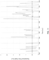
- FIG. 13 is a graph representing the result.
- the separation from the linear one did not become large up to an input pulse count rate of approximately 12 Mcps. Further, when exceeding 12 Mcps, the separation from the linear one somewhat became large, but the obtained count rate was not reduced. According to the X-ray measurement method of the present invention, the ranges of the reliable count rate are different in each model and formula, but calculation can be made up to infinity theoretically.
- ThScan was carried out with each of an exposure time of 40 ns and an exposure time of 16000 ns for 10 keV X-rays using a train bunch of Spring-8 to confirm difference in profile shape.
- ThScan is a method of measuring an X-ray intensity while changing a threshold (Threshold) that is set for the measurement. As to the optical system, change of the intensity with respect to the threshold can be measured under the same exposure condition.
- FIG. 14 is a graph representing the result. A clearly different profile was obtained as represented in FIG. 14 . Effectiveness obtained by being set to the exposure time not more than the time constant, and counted was confirmed from this graph.
- an amount of extension of exposure time at Threshold 5 keV is taken into consideration, thereby showing a graph of the value obtained by dividing it by 2.5. Taking the amount of extension of exposure time into consideration means that the sum of the exposure time and the time constant is used as a total time of exposure.
- FIG. 15 is a graph representing the result.
- the time constant ⁇ of an X-ray detector is 100 ns, and thus the substantial exposure time in total becomes 3.5 ms.
- the 40 ns exposure case though 3.5 ms exposure is substantially performed, has become higher in count rate than the 4 ms graph. In this manner, it is recognized that the influence of count loss is more able to be reduced by repeating exposure for a short duration than when performing exposure for a long duration.
Landscapes
- Physics & Mathematics (AREA)
- Health & Medical Sciences (AREA)
- Life Sciences & Earth Sciences (AREA)
- General Physics & Mathematics (AREA)
- High Energy & Nuclear Physics (AREA)
- Molecular Biology (AREA)
- Spectroscopy & Molecular Physics (AREA)
- Engineering & Computer Science (AREA)
- General Engineering & Computer Science (AREA)
- Biomedical Technology (AREA)
- General Health & Medical Sciences (AREA)
- Medical Informatics (AREA)
- Nuclear Medicine, Radiotherapy & Molecular Imaging (AREA)
- Optics & Photonics (AREA)
- Measurement Of Radiation (AREA)
Claims (7)
- Prozessierungsvorrichtung (200) umfassend:eine Speichersektion (220), die dazu konfiguriert ist, einen Ausgangswert zu speichern, der durch Zählen eines Pulssignals von einfallenden Röntgenstrahlen durch einen Halbleiterdetektor vom Photonenzählertyp (100) erhalten wurde; undeine Berechnungssektion (230), die dazu konfiguriert ist, basierend auf dem Ausgangswert, der gespeichert worden ist, einen Zählwert zu berechnen,dadurch gekennzeichnet, dass die Berechnungssektion (230) dazu konfiguriert ist, ein Modell zu verwenden, in dem eine scheinbare Zeitkonstante des Pulssignals gegenüber einer Zunahme eines Pulsdetektionsverhältnisses monoton abnimmt,wobei das Pulsdetektionsverhältnis einem Verhältnis einer Gesamtzeit, während der das Pulssignal detektiert wird, zu einer Gesamtzeit einer Exponierung entspricht, undwobei die scheinbare Zeitkonstante der Zeitkonstante des Pulssignals entspricht, wenn das Pulsdetektionsverhältnis Null ist, und wobei die scheinbare Zeitkonstante ein Produkt der Zeitkonstante des Pulssignals und einer Konstante ist, die kleiner als 1 ist, wenn das Pulsdetektionsverhältnis 1 ist, und die Zeitkonstante des Pulssignals eine Zeit ist, während der eine Intensität eines einzelnen Pulssignals einen Schwellenwert überschreitet.
- Prozessierungsvorrichtung (200) nach Anspruch 1,
wobei die Speichersektion (220) dazu konfiguriert ist, die Zeitkonstante des Pulssignals zu speichern, und wobei die Berechnungssektion (230) dazu konfiguriert ist, beim Verwenden des Modells die gespeicherte Zeitkonstante auszulesen und zu verwenden. - System (10) umfassend einen Halbleiterdetektor (100), und die Prozessierungsvorrichtung (200) nach Anspruch 1 oder 2.
- System (10) nach Anspruch 3,
wobei die Exponierung in einer kürzeren Zeit als der Zeitkonstante des Pulssignals mit dem Halbleiterdetektor (100) durchgeführt wird. - System (10) nach Anspruch 4,
wobei der Zählwert unter der Annahme, das das Pulssignal in einer Zeit gezählt wird, die durch Summieren der Zeitkonstante des Pulssignals und der Exponierungszeit für einen Frame erhalten wurde, bei der Berechnung des Zählwerts korrigiert wird. - Röntgenmessverfahren umfassend die Schritte:Auslesen eines Ausgangswerts, der durch Zählen eines Pulssignals von einfallenden Röntgenstrahlen durch einen Halbleiterdetektor vom Photonenzählertyp (100) erhalten wurde; undBerechnen eines Zählwerts basierend auf dem Ausgangswert, der ausgelesen worden ist,dadurch gekennzeichnet, dass ein Modell, in dem eine scheinbare Zeitkonstante des Pulssignals gegenüber einer Zunahme eines Pulsdetektionsverhältnisses monoton abnimmt, beim Schritt des Berechnens des Zählwerts verwendet wird,wobei das Pulsdetektionsverhältnis einem Verhältnis einer Gesamtzeit, während der das Pulssignal detektiert wird, zu einer Gesamtzeit einer Exponierung entspricht, undwobei die scheinbare Zeitkonstante der Zeitkonstante des Pulssignals entspricht, wenn das Pulsdetektionsverhältnis Null ist, und wobei die scheinbare Zeitkonstante ein Produkt der Zeitkonstante des Pulssignals und einer Konstante ist, die kleiner als 1 ist, wenn das Pulsdetektionsverhältnis 1 ist, und die Zeitkonstante des Pulssignals eine Zeit ist, während der eine Intensität eines einzelnen Pulssignals einen Schwellenwert überschreitet.
- Programm, das bewirkt, dass ein Computer die Prozesse ausführt:Auslesen eines Ausgangswerts, der durch Zählen eines Pulssignals von einfallenden Röntgenstrahlen durch einen Halbleiterdetektor vom Photonenzählertyp (100) erhalten wurde; undBerechnen eines Zählwerts basierend auf dem Ausgangswert, der ausgelesen worden ist,dadurch gekennzeichnet, dass ein Modell, in dem eine scheinbare Zeitkonstante des Pulssignals gegenüber einer Zunahme eines Pulsdetektionsverhältnisses monoton abnimmt, beim Prozessieren des Berechnens des Zählwerts verwendet wird,wobei das Pulsdetektionsverhältnis einem Verhältnis einer Gesamtzeit, während der das Pulssignal detektiert wird, zu einer Gesamtzeit einer Exponierung entspricht, und die scheinbare Zeitkonstante der Zeitkonstante des Pulssignals entspricht, wenn das Pulsdetektionsverhältnis Null ist, und wobei die scheinbare Zeitkonstante ein Produkt der Zeitkonstante des Pulssignals und einer Konstante ist, die kleiner als 1 ist, wenn das Pulsdetektionsverhältnis 1 ist, und die Zeitkonstante des Pulssignals eine Zeit ist, während der eine Intensität eines einzelnen Pulssignals einen Schwellenwert überschreitet.
Applications Claiming Priority (1)
| Application Number | Priority Date | Filing Date | Title |
|---|---|---|---|
| JP2019193745A JP7217528B2 (ja) | 2019-10-24 | 2019-10-24 | 処理装置、システム、x線測定方法およびプログラム |
Publications (2)
| Publication Number | Publication Date |
|---|---|
| EP3812797A1 EP3812797A1 (de) | 2021-04-28 |
| EP3812797B1 true EP3812797B1 (de) | 2024-10-02 |
Family
ID=73014243
Family Applications (1)
| Application Number | Title | Priority Date | Filing Date |
|---|---|---|---|
| EP20201937.8A Active EP3812797B1 (de) | 2019-10-24 | 2020-10-15 | Verarbeitungsvorrichtung, system, röntgenmessverfahren und programm |
Country Status (4)
| Country | Link |
|---|---|
| US (1) | US11221423B2 (de) |
| EP (1) | EP3812797B1 (de) |
| JP (1) | JP7217528B2 (de) |
| CN (1) | CN112711058B (de) |
Families Citing this family (3)
| Publication number | Priority date | Publication date | Assignee | Title |
|---|---|---|---|---|
| JP7444589B2 (ja) * | 2019-12-03 | 2024-03-06 | キヤノン株式会社 | 撮像装置およびその制御方法 |
| CN114040132B (zh) * | 2021-11-22 | 2023-11-21 | 成都微光集电科技有限公司 | 图像传感器及其曝光时序控制方法、系统及介质 |
| WO2024130309A1 (en) * | 2022-12-22 | 2024-06-27 | Southern Innovation International Pty Ltd | Input count rate measurement |
Citations (1)
| Publication number | Priority date | Publication date | Assignee | Title |
|---|---|---|---|---|
| EP2734861B1 (de) * | 2011-07-20 | 2017-12-20 | DECTRIS Ltd. | Photonenzählendes bildgebungsverfahren und vorrichtung mit sofortiger retrigger-funktion |
Family Cites Families (9)
| Publication number | Priority date | Publication date | Assignee | Title |
|---|---|---|---|---|
| JP2693203B2 (ja) * | 1989-01-25 | 1997-12-24 | アロカ株式会社 | 半導体放射線測定装置 |
| JP2855803B2 (ja) * | 1990-06-30 | 1999-02-10 | 株式会社島津製作所 | シンチレーションカメラ |
| DE10220293A1 (de) * | 2002-05-07 | 2003-11-27 | Philips Intellectual Property | Gerät und Verfahren zur Reduktion von Bildartefakten |
| JP5171891B2 (ja) | 2010-07-01 | 2013-03-27 | 三菱電機株式会社 | 放射線測定装置 |
| EP2437297A1 (de) * | 2010-10-01 | 2012-04-04 | Paul Scherrer Institut | Verfahren zur Korrektur von hohen Ratenineffizienzen eines Einzelphotonenzählungserkennungssystems und Einzelphotonenzählungserkennungssystem |
| RU2014143053A (ru) | 2012-03-27 | 2016-05-20 | Конинклейке Филипс Н.В. | Обычная визуализация посредством системы визуализации, содержащей детекторы для счета фотонов |
| CN104919729B (zh) * | 2013-01-25 | 2017-06-20 | 日本电信电话株式会社 | 光接收装置和相位周跳减少方法 |
| JP6182758B2 (ja) * | 2013-11-15 | 2017-08-23 | 株式会社リガク | 放射線検出器、これを用いたx線分析装置および放射線検出方法 |
| WO2017211880A1 (en) * | 2016-06-07 | 2017-12-14 | Koninklijke Philips N.V. | Dead-time calibration for a radiation detector |
-
2019
- 2019-10-24 JP JP2019193745A patent/JP7217528B2/ja active Active
-
2020
- 2020-10-15 EP EP20201937.8A patent/EP3812797B1/de active Active
- 2020-10-20 CN CN202011128545.2A patent/CN112711058B/zh active Active
- 2020-10-23 US US17/078,626 patent/US11221423B2/en active Active
Patent Citations (1)
| Publication number | Priority date | Publication date | Assignee | Title |
|---|---|---|---|---|
| EP2734861B1 (de) * | 2011-07-20 | 2017-12-20 | DECTRIS Ltd. | Photonenzählendes bildgebungsverfahren und vorrichtung mit sofortiger retrigger-funktion |
Also Published As
| Publication number | Publication date |
|---|---|
| US20210124066A1 (en) | 2021-04-29 |
| EP3812797A1 (de) | 2021-04-28 |
| CN112711058A (zh) | 2021-04-27 |
| US11221423B2 (en) | 2022-01-11 |
| CN112711058B (zh) | 2025-01-24 |
| JP2021067577A (ja) | 2021-04-30 |
| JP7217528B2 (ja) | 2023-02-03 |
Similar Documents
| Publication | Publication Date | Title |
|---|---|---|
| US11686863B2 (en) | Neural network-based corrector for photon counting detectors | |
| EP3812797B1 (de) | Verarbeitungsvorrichtung, system, röntgenmessverfahren und programm | |
| US8618495B2 (en) | Method and apparatus for analog pulse pile-up rejection | |
| CN102753963B (zh) | 使用材料的透射函数而辨识材料的方法及装置 | |
| US9689994B2 (en) | Method for correcting the stacking phenomenon applied to X-ray spectrums acquired using a spectrometric sensor | |
| CN101918858A (zh) | 辐射监测设备 | |
| Rasco et al. | Complete β-decay pattern for the high-priority decay-heat isotopes I 137 and Xe 137 determined using total absorption spectroscopy | |
| Khilkevitch et al. | Advanced algorithms for signal processing scintillation gamma ray detectors at high counting rates | |
| Mohammadian-Behbahani et al. | Pile-up correction algorithm based on successive integration for high count rate medical imaging and radiation spectroscopy | |
| JP2013512443A5 (de) | ||
| US4968889A (en) | Pulser injection with subsequent removal for gamma-ray spectrometry | |
| Watanabe et al. | Characterization of a neutron sensitive MCP/Timepix detector for quantitative image analysis at a pulsed neutron source | |
| JP2013061206A (ja) | 放射線核種分析装置及びその偶発同時計数抑制方法 | |
| US8676744B2 (en) | Physics-based, Bayesian sequential detection method and system for radioactive contraband | |
| EP3676640B1 (de) | Verfahren und systeme zur kalibrierung von partikeldetektoren | |
| Sabbatucci et al. | First principles pulse pile-up balance equation and fast deterministic solution | |
| Plagnard et al. | Metrological characterization of the ADONIS system used in gamma-ray spectrometry | |
| Elter et al. | Performance of Higher Order Campbell methods, Part II: calibration and experimental application | |
| Zhang et al. | Development of a pile-up pulse recovery algorithm for the LaBr3 detector | |
| Martín et al. | Wilcoxon signed-rank-based technique for the pulse-shape analysis of HPGe detectors | |
| Tang et al. | Real-time pulse pile-up separation algorithm for medical imaging at high count rate | |
| Ahsan et al. | The pulse-pile-up tail artifact in pulse-height spectra | |
| Alconada Verzini et al. | Determination of jet calibration and energy resolution in proton–proton collisions at√ s= 8TeV using the ATLAS detector | |
| Coulon et al. | Recent Developments in Count Rate Processing Associated with Radiation Monitoring Systems | |
| Leo | General Characteristics of Detectors |
Legal Events
| Date | Code | Title | Description |
|---|---|---|---|
| PUAI | Public reference made under article 153(3) epc to a published international application that has entered the european phase |
Free format text: ORIGINAL CODE: 0009012 |
|
| STAA | Information on the status of an ep patent application or granted ep patent |
Free format text: STATUS: THE APPLICATION HAS BEEN PUBLISHED |
|
| AK | Designated contracting states |
Kind code of ref document: A1 Designated state(s): AL AT BE BG CH CY CZ DE DK EE ES FI FR GB GR HR HU IE IS IT LI LT LU LV MC MK MT NL NO PL PT RO RS SE SI SK SM TR |
|
| AX | Request for extension of the european patent |
Extension state: BA ME |
|
| STAA | Information on the status of an ep patent application or granted ep patent |
Free format text: STATUS: REQUEST FOR EXAMINATION WAS MADE |
|
| 17P | Request for examination filed |
Effective date: 20211026 |
|
| RBV | Designated contracting states (corrected) |
Designated state(s): AL AT BE BG CH CY CZ DE DK EE ES FI FR GB GR HR HU IE IS IT LI LT LU LV MC MK MT NL NO PL PT RO RS SE SI SK SM TR |
|
| RIN1 | Information on inventor provided before grant (corrected) |
Inventor name: SAKUMA, YASUTAKA Inventor name: SAKUMURA, TAKUTO Inventor name: NAKAE, YASUKAZU Inventor name: KOBAYASHI, SHINTARO |
|
| STAA | Information on the status of an ep patent application or granted ep patent |
Free format text: STATUS: EXAMINATION IS IN PROGRESS |
|
| 17Q | First examination report despatched |
Effective date: 20221108 |
|
| GRAP | Despatch of communication of intention to grant a patent |
Free format text: ORIGINAL CODE: EPIDOSNIGR1 |
|
| STAA | Information on the status of an ep patent application or granted ep patent |
Free format text: STATUS: GRANT OF PATENT IS INTENDED |
|
| INTG | Intention to grant announced |
Effective date: 20240722 |
|
| GRAS | Grant fee paid |
Free format text: ORIGINAL CODE: EPIDOSNIGR3 |
|
| GRAA | (expected) grant |
Free format text: ORIGINAL CODE: 0009210 |
|
| STAA | Information on the status of an ep patent application or granted ep patent |
Free format text: STATUS: THE PATENT HAS BEEN GRANTED |
|
| AK | Designated contracting states |
Kind code of ref document: B1 Designated state(s): AL AT BE BG CH CY CZ DE DK EE ES FI FR GB GR HR HU IE IS IT LI LT LU LV MC MK MT NL NO PL PT RO RS SE SI SK SM TR |
|
| REG | Reference to a national code |
Ref country code: GB Ref legal event code: FG4D |
|
| REG | Reference to a national code |
Ref country code: CH Ref legal event code: EP |
|
| REG | Reference to a national code |
Ref country code: IE Ref legal event code: FG4D |
|
| REG | Reference to a national code |
Ref country code: DE Ref legal event code: R096 Ref document number: 602020038624 Country of ref document: DE |
|
| REG | Reference to a national code |
Ref country code: LT Ref legal event code: MG9D |
|
| REG | Reference to a national code |
Ref country code: NL Ref legal event code: MP Effective date: 20241002 |
|
| REG | Reference to a national code |
Ref country code: AT Ref legal event code: MK05 Ref document number: 1728890 Country of ref document: AT Kind code of ref document: T Effective date: 20241002 |
|
| PG25 | Lapsed in a contracting state [announced via postgrant information from national office to epo] |
Ref country code: NL Free format text: LAPSE BECAUSE OF FAILURE TO SUBMIT A TRANSLATION OF THE DESCRIPTION OR TO PAY THE FEE WITHIN THE PRESCRIBED TIME-LIMIT Effective date: 20241002 |
|
| PG25 | Lapsed in a contracting state [announced via postgrant information from national office to epo] |
Ref country code: NL Free format text: LAPSE BECAUSE OF FAILURE TO SUBMIT A TRANSLATION OF THE DESCRIPTION OR TO PAY THE FEE WITHIN THE PRESCRIBED TIME-LIMIT Effective date: 20241002 |
|
| PG25 | Lapsed in a contracting state [announced via postgrant information from national office to epo] |
Ref country code: PT Free format text: LAPSE BECAUSE OF FAILURE TO SUBMIT A TRANSLATION OF THE DESCRIPTION OR TO PAY THE FEE WITHIN THE PRESCRIBED TIME-LIMIT Effective date: 20250203 Ref country code: IS Free format text: LAPSE BECAUSE OF FAILURE TO SUBMIT A TRANSLATION OF THE DESCRIPTION OR TO PAY THE FEE WITHIN THE PRESCRIBED TIME-LIMIT Effective date: 20250202 Ref country code: HR Free format text: LAPSE BECAUSE OF FAILURE TO SUBMIT A TRANSLATION OF THE DESCRIPTION OR TO PAY THE FEE WITHIN THE PRESCRIBED TIME-LIMIT Effective date: 20241002 |
|
| PG25 | Lapsed in a contracting state [announced via postgrant information from national office to epo] |
Ref country code: FI Free format text: LAPSE BECAUSE OF FAILURE TO SUBMIT A TRANSLATION OF THE DESCRIPTION OR TO PAY THE FEE WITHIN THE PRESCRIBED TIME-LIMIT Effective date: 20241002 |
|
| PG25 | Lapsed in a contracting state [announced via postgrant information from national office to epo] |
Ref country code: BG Free format text: LAPSE BECAUSE OF FAILURE TO SUBMIT A TRANSLATION OF THE DESCRIPTION OR TO PAY THE FEE WITHIN THE PRESCRIBED TIME-LIMIT Effective date: 20241002 |
|
| PG25 | Lapsed in a contracting state [announced via postgrant information from national office to epo] |
Ref country code: ES Free format text: LAPSE BECAUSE OF FAILURE TO SUBMIT A TRANSLATION OF THE DESCRIPTION OR TO PAY THE FEE WITHIN THE PRESCRIBED TIME-LIMIT Effective date: 20241002 |
|
| PG25 | Lapsed in a contracting state [announced via postgrant information from national office to epo] |
Ref country code: NO Free format text: LAPSE BECAUSE OF FAILURE TO SUBMIT A TRANSLATION OF THE DESCRIPTION OR TO PAY THE FEE WITHIN THE PRESCRIBED TIME-LIMIT Effective date: 20250102 |
|
| PG25 | Lapsed in a contracting state [announced via postgrant information from national office to epo] |
Ref country code: AT Free format text: LAPSE BECAUSE OF FAILURE TO SUBMIT A TRANSLATION OF THE DESCRIPTION OR TO PAY THE FEE WITHIN THE PRESCRIBED TIME-LIMIT Effective date: 20241002 Ref country code: LV Free format text: LAPSE BECAUSE OF FAILURE TO SUBMIT A TRANSLATION OF THE DESCRIPTION OR TO PAY THE FEE WITHIN THE PRESCRIBED TIME-LIMIT Effective date: 20241002 Ref country code: GR Free format text: LAPSE BECAUSE OF FAILURE TO SUBMIT A TRANSLATION OF THE DESCRIPTION OR TO PAY THE FEE WITHIN THE PRESCRIBED TIME-LIMIT Effective date: 20250103 |
|
| PG25 | Lapsed in a contracting state [announced via postgrant information from national office to epo] |
Ref country code: PL Free format text: LAPSE BECAUSE OF FAILURE TO SUBMIT A TRANSLATION OF THE DESCRIPTION OR TO PAY THE FEE WITHIN THE PRESCRIBED TIME-LIMIT Effective date: 20241002 Ref country code: CZ Free format text: LAPSE BECAUSE OF FAILURE TO SUBMIT A TRANSLATION OF THE DESCRIPTION OR TO PAY THE FEE WITHIN THE PRESCRIBED TIME-LIMIT Effective date: 20241002 |
|
| PG25 | Lapsed in a contracting state [announced via postgrant information from national office to epo] |
Ref country code: RS Free format text: LAPSE BECAUSE OF FAILURE TO SUBMIT A TRANSLATION OF THE DESCRIPTION OR TO PAY THE FEE WITHIN THE PRESCRIBED TIME-LIMIT Effective date: 20250102 |
|
| PG25 | Lapsed in a contracting state [announced via postgrant information from national office to epo] |
Ref country code: SM Free format text: LAPSE BECAUSE OF FAILURE TO SUBMIT A TRANSLATION OF THE DESCRIPTION OR TO PAY THE FEE WITHIN THE PRESCRIBED TIME-LIMIT Effective date: 20241002 |
|
| REG | Reference to a national code |
Ref country code: DE Ref legal event code: R097 Ref document number: 602020038624 Country of ref document: DE |
|
| PG25 | Lapsed in a contracting state [announced via postgrant information from national office to epo] |
Ref country code: MC Free format text: LAPSE BECAUSE OF FAILURE TO SUBMIT A TRANSLATION OF THE DESCRIPTION OR TO PAY THE FEE WITHIN THE PRESCRIBED TIME-LIMIT Effective date: 20241002 |
|
| PG25 | Lapsed in a contracting state [announced via postgrant information from national office to epo] |
Ref country code: DK Free format text: LAPSE BECAUSE OF FAILURE TO SUBMIT A TRANSLATION OF THE DESCRIPTION OR TO PAY THE FEE WITHIN THE PRESCRIBED TIME-LIMIT Effective date: 20241002 |
|
| PG25 | Lapsed in a contracting state [announced via postgrant information from national office to epo] |
Ref country code: BE Free format text: LAPSE BECAUSE OF NON-PAYMENT OF DUE FEES Effective date: 20241031 Ref country code: LU Free format text: LAPSE BECAUSE OF NON-PAYMENT OF DUE FEES Effective date: 20241015 |
|
| PG25 | Lapsed in a contracting state [announced via postgrant information from national office to epo] |
Ref country code: EE Free format text: LAPSE BECAUSE OF FAILURE TO SUBMIT A TRANSLATION OF THE DESCRIPTION OR TO PAY THE FEE WITHIN THE PRESCRIBED TIME-LIMIT Effective date: 20241002 |
|
| PG25 | Lapsed in a contracting state [announced via postgrant information from national office to epo] |
Ref country code: RO Free format text: LAPSE BECAUSE OF FAILURE TO SUBMIT A TRANSLATION OF THE DESCRIPTION OR TO PAY THE FEE WITHIN THE PRESCRIBED TIME-LIMIT Effective date: 20241002 |
|
| PG25 | Lapsed in a contracting state [announced via postgrant information from national office to epo] |
Ref country code: SK Free format text: LAPSE BECAUSE OF FAILURE TO SUBMIT A TRANSLATION OF THE DESCRIPTION OR TO PAY THE FEE WITHIN THE PRESCRIBED TIME-LIMIT Effective date: 20241002 |
|
| PG25 | Lapsed in a contracting state [announced via postgrant information from national office to epo] |
Ref country code: IT Free format text: LAPSE BECAUSE OF FAILURE TO SUBMIT A TRANSLATION OF THE DESCRIPTION OR TO PAY THE FEE WITHIN THE PRESCRIBED TIME-LIMIT Effective date: 20241002 |
|
| REG | Reference to a national code |
Ref country code: BE Ref legal event code: MM Effective date: 20241031 |
|
| PLBE | No opposition filed within time limit |
Free format text: ORIGINAL CODE: 0009261 |
|
| STAA | Information on the status of an ep patent application or granted ep patent |
Free format text: STATUS: NO OPPOSITION FILED WITHIN TIME LIMIT |
|
| PG25 | Lapsed in a contracting state [announced via postgrant information from national office to epo] |
Ref country code: SE Free format text: LAPSE BECAUSE OF FAILURE TO SUBMIT A TRANSLATION OF THE DESCRIPTION OR TO PAY THE FEE WITHIN THE PRESCRIBED TIME-LIMIT Effective date: 20241002 |
|
| 26N | No opposition filed |
Effective date: 20250703 |
|
| GBPC | Gb: european patent ceased through non-payment of renewal fee |
Effective date: 20250102 |
|
| PG25 | Lapsed in a contracting state [announced via postgrant information from national office to epo] |
Ref country code: GB Free format text: LAPSE BECAUSE OF NON-PAYMENT OF DUE FEES Effective date: 20250102 |
|
| PG25 | Lapsed in a contracting state [announced via postgrant information from national office to epo] |
Ref country code: FR Free format text: LAPSE BECAUSE OF NON-PAYMENT OF DUE FEES Effective date: 20241202 |
|
| PG25 | Lapsed in a contracting state [announced via postgrant information from national office to epo] |
Ref country code: IE Free format text: LAPSE BECAUSE OF NON-PAYMENT OF DUE FEES Effective date: 20241015 |
|
| REG | Reference to a national code |
Ref country code: CH Ref legal event code: U11 Free format text: ST27 STATUS EVENT CODE: U-0-0-U10-U11 (AS PROVIDED BY THE NATIONAL OFFICE) Effective date: 20251101 |
|
| PGFP | Annual fee paid to national office [announced via postgrant information from national office to epo] |
Ref country code: DE Payment date: 20251021 Year of fee payment: 6 |
|
| PGFP | Annual fee paid to national office [announced via postgrant information from national office to epo] |
Ref country code: CH Payment date: 20251101 Year of fee payment: 6 |
|
| PG25 | Lapsed in a contracting state [announced via postgrant information from national office to epo] |
Ref country code: CY Free format text: LAPSE BECAUSE OF FAILURE TO SUBMIT A TRANSLATION OF THE DESCRIPTION OR TO PAY THE FEE WITHIN THE PRESCRIBED TIME-LIMIT; INVALID AB INITIO Effective date: 20201015 |
|
| PG25 | Lapsed in a contracting state [announced via postgrant information from national office to epo] |
Ref country code: HU Free format text: LAPSE BECAUSE OF FAILURE TO SUBMIT A TRANSLATION OF THE DESCRIPTION OR TO PAY THE FEE WITHIN THE PRESCRIBED TIME-LIMIT; INVALID AB INITIO Effective date: 20201015 |