EP3811103B1 - Dispositif radar et procédé de fonctionnement d'un dispositif radar - Google Patents
Dispositif radar et procédé de fonctionnement d'un dispositif radar Download PDFInfo
- Publication number
- EP3811103B1 EP3811103B1 EP19732878.4A EP19732878A EP3811103B1 EP 3811103 B1 EP3811103 B1 EP 3811103B1 EP 19732878 A EP19732878 A EP 19732878A EP 3811103 B1 EP3811103 B1 EP 3811103B1
- Authority
- EP
- European Patent Office
- Prior art keywords
- frequency
- signal
- oscillator
- generated
- comb generator
- Prior art date
- Legal status (The legal status is an assumption and is not a legal conclusion. Google has not performed a legal analysis and makes no representation as to the accuracy of the status listed.)
- Active
Links
- 238000000034 method Methods 0.000 title claims description 19
- 238000004458 analytical method Methods 0.000 claims description 6
- 239000000203 mixture Substances 0.000 claims description 5
- 230000001960 triggered effect Effects 0.000 claims 2
- 238000005259 measurement Methods 0.000 description 11
- 238000001514 detection method Methods 0.000 description 9
- 238000001228 spectrum Methods 0.000 description 9
- 239000000463 material Substances 0.000 description 7
- 230000005540 biological transmission Effects 0.000 description 5
- 238000010586 diagram Methods 0.000 description 5
- 230000003595 spectral effect Effects 0.000 description 4
- 239000000969 carrier Substances 0.000 description 2
- 230000001419 dependent effect Effects 0.000 description 2
- 238000011161 development Methods 0.000 description 2
- 230000018109 developmental process Effects 0.000 description 2
- 230000003287 optical effect Effects 0.000 description 2
- 239000000047 product Substances 0.000 description 2
- 238000011084 recovery Methods 0.000 description 2
- 239000011435 rock Substances 0.000 description 2
- 238000007493 shaping process Methods 0.000 description 2
- 230000015572 biosynthetic process Effects 0.000 description 1
- 238000006243 chemical reaction Methods 0.000 description 1
- 230000008878 coupling Effects 0.000 description 1
- 238000010168 coupling process Methods 0.000 description 1
- 238000005859 coupling reaction Methods 0.000 description 1
- 230000000694 effects Effects 0.000 description 1
- 238000005516 engineering process Methods 0.000 description 1
- 238000005206 flow analysis Methods 0.000 description 1
- 238000003384 imaging method Methods 0.000 description 1
- 238000004519 manufacturing process Methods 0.000 description 1
- 238000005457 optimization Methods 0.000 description 1
- 230000000704 physical effect Effects 0.000 description 1
- 238000000275 quality assurance Methods 0.000 description 1
- 239000013589 supplement Substances 0.000 description 1
- 230000009466 transformation Effects 0.000 description 1
- 230000001052 transient effect Effects 0.000 description 1
- 230000000007 visual effect Effects 0.000 description 1
Images


Classifications
-
- G—PHYSICS
- G01—MEASURING; TESTING
- G01S—RADIO DIRECTION-FINDING; RADIO NAVIGATION; DETERMINING DISTANCE OR VELOCITY BY USE OF RADIO WAVES; LOCATING OR PRESENCE-DETECTING BY USE OF THE REFLECTION OR RERADIATION OF RADIO WAVES; ANALOGOUS ARRANGEMENTS USING OTHER WAVES
- G01S13/00—Systems using the reflection or reradiation of radio waves, e.g. radar systems; Analogous systems using reflection or reradiation of waves whose nature or wavelength is irrelevant or unspecified
- G01S13/02—Systems using reflection of radio waves, e.g. primary radar systems; Analogous systems
- G01S13/06—Systems determining position data of a target
- G01S13/08—Systems for measuring distance only
- G01S13/32—Systems for measuring distance only using transmission of continuous waves, whether amplitude-, frequency-, or phase-modulated, or unmodulated
- G01S13/34—Systems for measuring distance only using transmission of continuous waves, whether amplitude-, frequency-, or phase-modulated, or unmodulated using transmission of continuous, frequency-modulated waves while heterodyning the received signal, or a signal derived therefrom, with a locally-generated signal related to the contemporaneously transmitted signal
- G01S13/347—Systems for measuring distance only using transmission of continuous waves, whether amplitude-, frequency-, or phase-modulated, or unmodulated using transmission of continuous, frequency-modulated waves while heterodyning the received signal, or a signal derived therefrom, with a locally-generated signal related to the contemporaneously transmitted signal using more than one modulation frequency
-
- G—PHYSICS
- G01—MEASURING; TESTING
- G01S—RADIO DIRECTION-FINDING; RADIO NAVIGATION; DETERMINING DISTANCE OR VELOCITY BY USE OF RADIO WAVES; LOCATING OR PRESENCE-DETECTING BY USE OF THE REFLECTION OR RERADIATION OF RADIO WAVES; ANALOGOUS ARRANGEMENTS USING OTHER WAVES
- G01S7/00—Details of systems according to groups G01S13/00, G01S15/00, G01S17/00
- G01S7/02—Details of systems according to groups G01S13/00, G01S15/00, G01S17/00 of systems according to group G01S13/00
- G01S7/03—Details of HF subsystems specially adapted therefor, e.g. common to transmitter and receiver
-
- G—PHYSICS
- G01—MEASURING; TESTING
- G01S—RADIO DIRECTION-FINDING; RADIO NAVIGATION; DETERMINING DISTANCE OR VELOCITY BY USE OF RADIO WAVES; LOCATING OR PRESENCE-DETECTING BY USE OF THE REFLECTION OR RERADIATION OF RADIO WAVES; ANALOGOUS ARRANGEMENTS USING OTHER WAVES
- G01S7/00—Details of systems according to groups G01S13/00, G01S15/00, G01S17/00
- G01S7/02—Details of systems according to groups G01S13/00, G01S15/00, G01S17/00 of systems according to group G01S13/00
- G01S7/35—Details of non-pulse systems
Definitions
- a signal detection device for determining the presence of one or more or a plurality of predetermined signal frequencies is known. It is an object of the WO99/35510 A1 to provide a radar/laser detector for locating signals along multiple frequency bands.
- Radar systems that work with frequency steps (Frequency Stepped Continuous Wave - FSCW) are also known. Such radar systems can achieve a very high level of accuracy because it is possible to evaluate the signals in the correct phase.
- a disadvantage of such systems is that each frequency for the primary signal to be generated must be generated and switched individually. In addition, after each switchover, it is necessary to wait until a stable system state has been established before the reflected signal can be properly evaluated by the receiver unit.
- the FSCW system is therefore only suitable to a limited extent for radar applications that require high measuring speeds, because the measuring time of these systems is relatively long.
- the frequency generators in the transmitter unit and the receiver unit must be switched at the same time, for example. It must also be ensured that the radar arrangement in both the transmitter unit and the receiver unit are in a steady state. This includes, for example, complete propagation of the signal and the decay of transient signals in the filters. Depending on the required unambiguousness range, this process must be repeated several hundred times. The required measurement time with such a radar arrangement is therefore relatively high.
- the primary signal thus contains two or more frequency components.
- Such a frequency comb generator is arranged both in the transmitting unit and in the receiving unit of a radar arrangement according to the invention.
- a special feature of this mixed signal is that the frequency spacing between the individual frequency components of the mixed signal is also equidistant but not identical to the frequencies of the individual frequency components of the primary signal. There is a frequency shift of the frequency components between the frequency components of the primary signal and the frequency components of the mixed signal. In one example, the frequency components of the mixed signal are shifted to higher frequencies compared to the frequency components of the primary signal. Such a shift can be, for example, 50 MHz or 0.5 MHz.
- the intermediate frequency signal is no longer narrowband, but contains at least two signals at different frequencies.
- the invention thus provides a possibility with which many frequency components can be generated in parallel, emitted and subsequently received with little effort and then separated and analyzed by means of preferably digital signal processing.
- An application of the invention can be used, for example, in the automotive radar sector when a high measuring speed is required.
- the present invention can also be used in the field of material flow analysis, for example in the fields of agriculture or industry.
- fast-moving materials can, for example, be materials moving in an air stream inside or outside a tube.
- the moisture content in a moving material such as grain can be determined in this way.
- Such an object can be a projectile, for example.
- the invention can be a supplement or a replacement for existing known systems such as LIDAR or camera-based sensor systems.
- the signal quality, in particular phase noise, of the primary signals generated by means of a frequency comb generator in a transmitting unit of a radar arrangement according to the invention is higher than when using a phase-locked loop (PLL) according to the prior art.
- PLL phase-locked loop
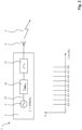
- the received reflected signal 7 is amplified, for example by means of an input amplifier 10, whereby an amplified, high-frequency reflected signal 22 is generated, and is fed to an input of a mixer 12.
- a second oscillator 11 is connected to a second input of the mixer 12, which generates a mixing frequency or a second oscillator frequency 28, with which the mixer 12 converts the amplified, high-frequency reflected signal 22 into an intermediate frequency 13.
- this intermediate frequency 13 can be filtered by means of a first band filter 14 and converted into a digital signal in an analog-digital converter 15.
- the digital signal or digital intermediate frequency signal 26 provided in this way is converted into a further Figure 1 further processed or analyzed by a unit not shown. In this analysis, properties of the object or target 6 such as distance, position or angle, direction of movement are determined.
- first oscillator frequencies 27 must be generated in succession in the first oscillator 3 for the primary signal 5.
- e e O + n ⁇ ⁇ e
- a transmitting unit 2 of an FSCW radar system 1 is shown with a first frequency comb generator 16.
- the transmitting unit 2 has a first oscillator 3 for generating a first oscillator frequency 27 with which the first frequency comb generator 16 is controlled.
- the first frequency comb generator 16 provides a primary signal 5 with several equally spaced frequency components at its output.
- the primary signal 5 generated in this way is filtered by a second band filter 17 and emitted via the transmitting antenna 4 of the transmitting unit 2.
- frequency components generated by the second frequency comb generator 18 are equally spaced from one another, as are the frequency components generated by the first frequency comb generator 16 in the transmitting unit 2. In this example, however, the frequency components generated by the second frequency comb generator 18 are slightly further apart, which in the example, with a distance of 100.5 MHz between the frequency components of the second frequency comb generator 18, is 0.5 MHz more.
- the intermediate frequency signal 13 has, for example, the frequencies 0.05 GHz, 0.10 GHz, 0.15 GHz, 0.20 GHz, 0.25 GHz, 0.30 GHz, 0.35 GHz and 0.40 GHz.
Landscapes
- Engineering & Computer Science (AREA)
- Radar, Positioning & Navigation (AREA)
- Remote Sensing (AREA)
- Computer Networks & Wireless Communication (AREA)
- Physics & Mathematics (AREA)
- General Physics & Mathematics (AREA)
- Radar Systems Or Details Thereof (AREA)
Claims (12)
- Dispositif radar (1), comprenant une unité d'émission (2) comportant un premier oscillateur (3) ainsi qu'une antenne d'émission (4) et une unité de réception (9) comportant un deuxième oscillateur (11), un premier mélangeur (12) ainsi qu'une antenne de réception (8), dans lequelun premier générateur de peigne de fréquences (16) est disposé dans l'unité d'émission (2) entre le premier oscillateur (3) et l'antenne d'émission (4), dans lequel les multiples composantes de fréquence du signal primaire générées par le premier générateur de peigne de fréquences sont équidistantes les unes des autres, et dans lequelun deuxième générateur de peigne de fréquences (18) est disposé dans l'unité de réception (9) entre le deuxième oscillateur (11) et le premier mélangeur (12), et génère de multiples composantes de fréquence d'un signal mélangé (25) qui sont équidistantes les unes des autres et décalées en fréquence par rapport aux composantes de fréquence du signal primaire (5).
- Dispositif radar (1) selon la revendication 1, caractérisé en ce qu'un deuxième mélangeur (20) est disposé dans l'unité de réception (9) entre le deuxième générateur de peigne de fréquences (18) et le premier mélangeur (12), dans lequel le deuxième mélangeur (20) est relié à un troisième oscillateur (21).
- Dispositif radar (1) selon la revendication 1 ou 2, caractérisé en ce qu'un deuxième filtre passe-bande (17) est disposé dans l'unité d'émission (2) entre le premier générateur de peigne de fréquences (16) et l'antenne d'émission (4).
- Dispositif radar (1) selon l'une quelconque des revendications 1 à 3, caractérisé en ce qu'un troisième filtre passe-bande (19) est disposé entre le deuxième générateur de peigne de fréquences (18) et le deuxième mélangeur (20).
- Dispositif radar (1) selon l'une quelconque des revendications 1 à 4, caractérisé en ce qu'un quatrième filtre passe-bande (23) est disposé entre le deuxième mélangeur (20) et le premier mélangeur (12).
- Dispositif radar (1) selon l'une quelconque des revendications 1 à 5, caractérisé en ce qu'une sortie du premier mélangeur (12) est reliée à une entrée d'un convertisseur analogique-numérique (15) et en ce que le convertisseur analogique-numérique (15) comporte une sortie destinée à délivrer un signal numérique à fréquence intermédiaire (26).
- Procédé de fonctionnement d'un dispositif radar (1), dans lequel il est fourni une première fréquence d'oscillateur (27) à partir de laquelle un signal primaire (5) est généré au moins indirectement et est émis par l'intermédiaire d'une antenne d'émission (4) et dans lequel il est fourni une deuxième fréquence d'oscillateur (28) au moyen de laquelle une fréquence intermédiaire (13) est générée au moins indirectement par un mélange d'un signal réfléchi reçu (7) avec la deuxième fréquence d'oscillateur (28), dans lequel,côté émetteur, un premier générateur de peigne de fréquences (16) est commandé à la première fréquence d'oscillateur (27) pour générer un signal primaire (5) contenant de multiples composantes de fréquence, dans lequel,côté récepteur, un deuxième générateur de peigne de fréquences (18) est commandé à la deuxième fréquence d'oscillateur (28) pour générer un signal de sortie contenant de multiples composantes de fréquence, dans lequelle signal de sortie ainsi généré est mélangé à une troisième fréquence d'oscillateur (29) et un signal mélangé (25) est généré, et dans lequella fréquence intermédiaire (13) est générée par un mélange du signal réfléchi reçu (7) au signal mélangé (25), dans lequel les multiples composantes de fréquence du signal primaire (5) générées côté émetteur par le premier générateur de peigne de fréquences (16) sont générées à équidistance les unes des autres, et dans lequelles multiples composantes de fréquence du signal mélangé (25) générées côté récepteur par le deuxième générateur de peigne de fréquences (18) sont générées à équidistance les unes des autres et décalées en fréquence par rapport aux composantes de fréquence du signal primaire (5).
- Procédé selon la revendication 7, caractérisé en ce que le signal primaire (5) généré par le premier générateur de peigne de fréquences (16) est filtré au moyen d'un deuxième filtre passe-bande (17) avant d'être rayonné par l'intermédiaire d'une antenne d'émission (4).
- Procédé selon la revendication 7 ou 8, caractérisé en ce que le signal de sortie du deuxième générateur de peigne de fréquences (18) contenant de multiples composantes de fréquence est filtré au moyen d'un troisième filtre passe-bande (19) avant d'être mélangé à la troisième fréquence d'oscillateur (29).
- Procédé selon l'une quelconque des revendications 7 à 9, caractérisé en ce que le signal mélangé (25) est filtré au moyen d'un quatrième filtre passe-bande (23) avant d'être mélangé au signal réfléchi reçu (7).
- Procédé selon l'une quelconque des revendications 7 à 10, caractérisé en ce que la fréquence intermédiaire (13) est convertie en un signal numérique à fréquence intermédiaire (26) au moyen d'un convertisseur analogique-numérique (15) et est délivrée en vue d'un traitement ou d'une analyse ultérieur(e).
- Procédé selon l'une quelconque des revendications 7 à 11, caractérisé en ce que le traitement ou l'analyse ultérieur(e) du signal numérique à fréquence intermédiaire (26) est effectué(e) dans le dispositif radar (1) et en ce que des informations concernant des objets, telles que leur distance, leur position ou leur angle, leur direction de déplacement et leur vitesse et/ou des propriétés des objets, sont ainsi déterminées.
Applications Claiming Priority (2)
| Application Number | Priority Date | Filing Date | Title |
|---|---|---|---|
| DE102018115079.2A DE102018115079B4 (de) | 2018-06-22 | 2018-06-22 | Radaranordnung und Verfahren zum Betreiben einer Radaranordnung |
| PCT/DE2019/100436 WO2019242794A1 (fr) | 2018-06-22 | 2019-05-14 | Dispositif radar et procédé de fonctionnement d'un dispositif radar |
Publications (3)
| Publication Number | Publication Date |
|---|---|
| EP3811103A1 EP3811103A1 (fr) | 2021-04-28 |
| EP3811103B1 true EP3811103B1 (fr) | 2024-07-10 |
| EP3811103C0 EP3811103C0 (fr) | 2024-07-10 |
Family
ID=67003142
Family Applications (1)
| Application Number | Title | Priority Date | Filing Date |
|---|---|---|---|
| EP19732878.4A Active EP3811103B1 (fr) | 2018-06-22 | 2019-05-14 | Dispositif radar et procédé de fonctionnement d'un dispositif radar |
Country Status (4)
| Country | Link |
|---|---|
| US (1) | US11953583B2 (fr) |
| EP (1) | EP3811103B1 (fr) |
| DE (2) | DE102018115079B4 (fr) |
| WO (1) | WO2019242794A1 (fr) |
Family Cites Families (27)
| Publication number | Priority date | Publication date | Assignee | Title |
|---|---|---|---|---|
| US3928851A (en) * | 1960-08-31 | 1975-12-23 | Us Navy | Object locator system |
| US3894293A (en) * | 1963-01-29 | 1975-07-08 | Us Navy | Object locator system with automatic sensitivity reduction for large signals |
| US3939474A (en) * | 1965-09-20 | 1976-02-17 | Rockwell International Corporation | Fully-coherent multiple frequency radar system |
| US3885240A (en) * | 1967-06-27 | 1975-05-20 | Us Navy | Storage radar system |
| US3500303A (en) * | 1968-03-14 | 1970-03-10 | Gen Electric | Signal generator for producing a set of signals of common frequency and adjustable phase slope |
| US3631490A (en) * | 1969-03-17 | 1971-12-28 | Sperry Rand Corp | Signal processor for reducing clutter and eliminating range ambiguities in target detection systems |
| US4504833A (en) * | 1981-12-09 | 1985-03-12 | Xadar Corporation | Synthetic pulse radar system and method |
| US6002707A (en) * | 1983-04-04 | 1999-12-14 | Honeywell, Inc. | Spread signal spectrum communication circuits and system |
| US4983978A (en) * | 1989-03-21 | 1991-01-08 | United Technologies Corporation | Multi-frequency comb generator for radar and the like |
| MY107298A (en) * | 1989-09-18 | 1995-10-31 | Univ Sydney Technology | Random access multiple user communication system. |
| FR2652653B1 (fr) * | 1989-09-29 | 1991-12-13 | Centre Nat Rech Scient | Analyseur vectoriel de reseau millimetrique et/ou submillimetrique. |
| US4982165A (en) * | 1989-10-20 | 1991-01-01 | Raytheon Company | Set-on oscillator |
| GB2240240A (en) * | 1990-01-19 | 1991-07-24 | Philips Electronic Associated | Radio receiver for direct sequence spread spectrum signals |
| US5239309A (en) * | 1991-06-27 | 1993-08-24 | Hughes Aircraft Company | Ultra wideband radar employing synthesized short pulses |
| US5146616A (en) * | 1991-06-27 | 1992-09-08 | Hughes Aircraft Company | Ultra wideband radar transmitter employing synthesized short pulses |
| US5729570A (en) * | 1994-12-08 | 1998-03-17 | Stanford Telecommunications, Inc. | Orthogonal code division multiple access communication system having multicarrier modulation |
| US5784403A (en) * | 1995-02-03 | 1998-07-21 | Omnipoint Corporation | Spread spectrum correlation using saw device |
| US5923280A (en) * | 1997-01-17 | 1999-07-13 | Automotive Systems Laboratory, Inc. | Vehicle collision radar with randomized FSK wave form |
| US6085151A (en) * | 1998-01-20 | 2000-07-04 | Automotive Systems Laboratory, Inc. | Predictive collision sensing system |
| US5969667A (en) * | 1997-10-16 | 1999-10-19 | Automotive Systems Laboratory, Inc. | Radar system |
| DE19748608A1 (de) * | 1997-11-04 | 1999-05-06 | Daimler Benz Aerospace Ag | Sampling-PLL für hochauflösende Radarsysteme |
| AU2107899A (en) * | 1998-01-07 | 1999-07-26 | Cobra Electronics Corp. | Multiple-band radar detector |
| US6570458B2 (en) * | 2001-06-12 | 2003-05-27 | Teradyne, Inc. | Low noise microwave synthesizer employing high frequency combs for tuning drift cancel loop |
| JP5630122B2 (ja) * | 2010-07-28 | 2014-11-26 | 富士通株式会社 | イメージング装置及び送受信装置 |
| US10018714B2 (en) * | 2015-06-24 | 2018-07-10 | The United States Of America As Represented By The Secretary Of The Army | Two-dimensional RF harmonic imaging system and algorithm |
| CA2932816A1 (fr) * | 2016-06-14 | 2017-12-14 | Degelman Industries Ltd. | Rouleau a terrain |
| US10560110B1 (en) * | 2016-06-28 | 2020-02-11 | Giga-Tronics Incorporated | Precision microwave frequency synthesizer and receiver with delay balanced drift canceling loop |
-
2018
- 2018-06-22 DE DE102018115079.2A patent/DE102018115079B4/de active Active
-
2019
- 2019-05-14 EP EP19732878.4A patent/EP3811103B1/fr active Active
- 2019-05-14 DE DE112019003133.3T patent/DE112019003133A5/de not_active Withdrawn
- 2019-05-14 WO PCT/DE2019/100436 patent/WO2019242794A1/fr active Application Filing
- 2019-05-14 US US17/253,881 patent/US11953583B2/en active Active
Also Published As
| Publication number | Publication date |
|---|---|
| US11953583B2 (en) | 2024-04-09 |
| EP3811103A1 (fr) | 2021-04-28 |
| DE102018115079B4 (de) | 2020-01-30 |
| DE112019003133A5 (de) | 2021-04-08 |
| US20210270953A1 (en) | 2021-09-02 |
| DE102018115079A1 (de) | 2019-12-24 |
| EP3811103C0 (fr) | 2024-07-10 |
| WO2019242794A1 (fr) | 2019-12-26 |
Similar Documents
| Publication | Publication Date | Title |
|---|---|---|
| EP3418701B1 (fr) | Réflectomètre de niveau de remplissage à déroulement de mesure modifiable | |
| EP2753950B1 (fr) | Capteur de radar imageur à grossissement synthétique de l'ouverture d'antenne et à balayage bidimensionnel du faisceau | |
| EP2507649B1 (fr) | Procédé de détermination univoque d'une distance et/ou d'une vitesse relative d'un objet, système d'assistance au conducteur et véhicule à moteur | |
| DE102014009650A1 (de) | Verfahren und Vorrichtung zum Erfassen der Umgebung auf der Grundlage von frequenzmoduliertem Dauerstrichradar | |
| DE102011113018A1 (de) | Abbildender Radarsensor mit schmaler Antennenkeule und weitem Winkel-Detektionsbereich | |
| DE112006001114T5 (de) | Radargerät | |
| DE102006032540A1 (de) | Winkelauflösender Radarsensor | |
| DE102015107419A1 (de) | Radarvorrichtung | |
| EP3679391B1 (fr) | Capteur radar à modulation de fréquence d'ondes continues (fmcw) pourvu de modules à haute fréquence synchronisés | |
| DE102015210676A1 (de) | Fmcw-radarvorrichtung und fmcw-radarsignal-verarbeitungsverfahren | |
| DE102019102077A1 (de) | Vorrichtung zum Verarbeiten eines Signals eines Ortungssystems sowie Verfahren zum Simulieren und zum Orten eines Objekts | |
| DE102009047931B4 (de) | Verfahren und Vorrichtung zur Bestimmung von Abstand und Relativgeschwindigkeit wenigstens eines entfernten Objektes | |
| DE102007042954A1 (de) | Mikrowellen-Näherungssensor und Verfahren zur Ermittlung des Abstands zwischen einem Messkopf und einem Zielobjekt | |
| DE102013216461A1 (de) | Synthetik-Apertur-Radarverfahren | |
| DE2133395C3 (de) | Einrichtung zur Kompensation der Eigenbewegung einer kohärenten Impuls-Doppler-Radaranlage | |
| DE112014006066T5 (de) | Radarvorrichtung sowie Distanz- und Geschwindigkeitsmessverfahren | |
| WO2020225314A1 (fr) | Système de radar multistatique cohérent, en particulier pour une utilisation dans un véhicule | |
| DE102004062023B4 (de) | Radarsystem zur Überwachung von Zielen in verschiedenen Entfernungsbereichen | |
| EP3811103B1 (fr) | Dispositif radar et procédé de fonctionnement d'un dispositif radar | |
| DE102013109279A1 (de) | Radarleistungsüberwachungsvorrichtung, Pulskompressionsradargerät und Radarleistungsfähigkeitsmessverfahren | |
| DE102015013389A1 (de) | Verfahren zur Detektion eines schnellen Ziels mittels einer Radaranlage | |
| DE2848625A1 (de) | Anordnung zum gebrauch in einem flugzeug zum detektieren von hindernissen | |
| EP3009858A1 (fr) | Dispositif radar de détection des nuages | |
| EP3064960B1 (fr) | Procede de fonctionnement d'un detecteur radar a ondes entretenues et detecteur radar a ondes entretenues | |
| DE102011051969B4 (de) | Radargerät und Verfahren zum Betreiben des Radargerätes |
Legal Events
| Date | Code | Title | Description |
|---|---|---|---|
| STAA | Information on the status of an ep patent application or granted ep patent |
Free format text: STATUS: UNKNOWN |
|
| STAA | Information on the status of an ep patent application or granted ep patent |
Free format text: STATUS: THE INTERNATIONAL PUBLICATION HAS BEEN MADE |
|
| STAA | Information on the status of an ep patent application or granted ep patent |
Free format text: STATUS: THE INTERNATIONAL PUBLICATION HAS BEEN MADE |
|
| PUAI | Public reference made under article 153(3) epc to a published international application that has entered the european phase |
Free format text: ORIGINAL CODE: 0009012 |
|
| STAA | Information on the status of an ep patent application or granted ep patent |
Free format text: STATUS: REQUEST FOR EXAMINATION WAS MADE |
|
| 17P | Request for examination filed |
Effective date: 20201210 |
|
| AK | Designated contracting states |
Kind code of ref document: A1 Designated state(s): AL AT BE BG CH CY CZ DE DK EE ES FI FR GB GR HR HU IE IS IT LI LT LU LV MC MK MT NL NO PL PT RO RS SE SI SK SM TR |
|
| AX | Request for extension of the european patent |
Extension state: BA ME |
|
| DAV | Request for validation of the european patent (deleted) | ||
| DAX | Request for extension of the european patent (deleted) | ||
| RAP1 | Party data changed (applicant data changed or rights of an application transferred) |
Owner name: ALTAVO GMBH |
|
| GRAP | Despatch of communication of intention to grant a patent |
Free format text: ORIGINAL CODE: EPIDOSNIGR1 |
|
| STAA | Information on the status of an ep patent application or granted ep patent |
Free format text: STATUS: GRANT OF PATENT IS INTENDED |
|
| INTG | Intention to grant announced |
Effective date: 20240131 |
|
| GRAS | Grant fee paid |
Free format text: ORIGINAL CODE: EPIDOSNIGR3 |
|
| GRAA | (expected) grant |
Free format text: ORIGINAL CODE: 0009210 |
|
| STAA | Information on the status of an ep patent application or granted ep patent |
Free format text: STATUS: THE PATENT HAS BEEN GRANTED |
|
| AK | Designated contracting states |
Kind code of ref document: B1 Designated state(s): AL AT BE BG CH CY CZ DE DK EE ES FI FR GB GR HR HU IE IS IT LI LT LU LV MC MK MT NL NO PL PT RO RS SE SI SK SM TR |
|
| REG | Reference to a national code |
Ref country code: CH Ref legal event code: EP |
|
| REG | Reference to a national code |
Ref country code: DE Ref legal event code: R096 Ref document number: 502019011644 Country of ref document: DE |
|
| U01 | Request for unitary effect filed |
Effective date: 20240810 |