EP3811103B1 - Radar assembly and method for operating a radar assembly - Google Patents
Radar assembly and method for operating a radar assembly Download PDFInfo
- Publication number
- EP3811103B1 EP3811103B1 EP19732878.4A EP19732878A EP3811103B1 EP 3811103 B1 EP3811103 B1 EP 3811103B1 EP 19732878 A EP19732878 A EP 19732878A EP 3811103 B1 EP3811103 B1 EP 3811103B1
- Authority
- EP
- European Patent Office
- Prior art keywords
- frequency
- signal
- oscillator
- generated
- comb generator
- Prior art date
- Legal status (The legal status is an assumption and is not a legal conclusion. Google has not performed a legal analysis and makes no representation as to the accuracy of the status listed.)
- Active
Links
- 238000000034 method Methods 0.000 title claims description 19
- 238000004458 analytical method Methods 0.000 claims description 6
- 239000000203 mixture Substances 0.000 claims description 5
- 230000001960 triggered effect Effects 0.000 claims 2
- 238000005259 measurement Methods 0.000 description 11
- 238000001514 detection method Methods 0.000 description 9
- 238000001228 spectrum Methods 0.000 description 9
- 239000000463 material Substances 0.000 description 7
- 230000005540 biological transmission Effects 0.000 description 5
- 238000010586 diagram Methods 0.000 description 5
- 230000003595 spectral effect Effects 0.000 description 4
- 239000000969 carrier Substances 0.000 description 2
- 230000001419 dependent effect Effects 0.000 description 2
- 238000011161 development Methods 0.000 description 2
- 230000018109 developmental process Effects 0.000 description 2
- 230000003287 optical effect Effects 0.000 description 2
- 239000000047 product Substances 0.000 description 2
- 238000011084 recovery Methods 0.000 description 2
- 239000011435 rock Substances 0.000 description 2
- 238000007493 shaping process Methods 0.000 description 2
- 230000015572 biosynthetic process Effects 0.000 description 1
- 238000006243 chemical reaction Methods 0.000 description 1
- 230000008878 coupling Effects 0.000 description 1
- 238000010168 coupling process Methods 0.000 description 1
- 238000005859 coupling reaction Methods 0.000 description 1
- 230000000694 effects Effects 0.000 description 1
- 238000005516 engineering process Methods 0.000 description 1
- 238000005206 flow analysis Methods 0.000 description 1
- 238000003384 imaging method Methods 0.000 description 1
- 238000004519 manufacturing process Methods 0.000 description 1
- 238000005457 optimization Methods 0.000 description 1
- 230000000704 physical effect Effects 0.000 description 1
- 238000000275 quality assurance Methods 0.000 description 1
- 239000013589 supplement Substances 0.000 description 1
- 230000009466 transformation Effects 0.000 description 1
- 230000001052 transient effect Effects 0.000 description 1
- 230000000007 visual effect Effects 0.000 description 1
Images


Classifications
-
- G—PHYSICS
- G01—MEASURING; TESTING
- G01S—RADIO DIRECTION-FINDING; RADIO NAVIGATION; DETERMINING DISTANCE OR VELOCITY BY USE OF RADIO WAVES; LOCATING OR PRESENCE-DETECTING BY USE OF THE REFLECTION OR RERADIATION OF RADIO WAVES; ANALOGOUS ARRANGEMENTS USING OTHER WAVES
- G01S13/00—Systems using the reflection or reradiation of radio waves, e.g. radar systems; Analogous systems using reflection or reradiation of waves whose nature or wavelength is irrelevant or unspecified
- G01S13/02—Systems using reflection of radio waves, e.g. primary radar systems; Analogous systems
- G01S13/06—Systems determining position data of a target
- G01S13/08—Systems for measuring distance only
- G01S13/32—Systems for measuring distance only using transmission of continuous waves, whether amplitude-, frequency-, or phase-modulated, or unmodulated
- G01S13/34—Systems for measuring distance only using transmission of continuous waves, whether amplitude-, frequency-, or phase-modulated, or unmodulated using transmission of continuous, frequency-modulated waves while heterodyning the received signal, or a signal derived therefrom, with a locally-generated signal related to the contemporaneously transmitted signal
- G01S13/347—Systems for measuring distance only using transmission of continuous waves, whether amplitude-, frequency-, or phase-modulated, or unmodulated using transmission of continuous, frequency-modulated waves while heterodyning the received signal, or a signal derived therefrom, with a locally-generated signal related to the contemporaneously transmitted signal using more than one modulation frequency
-
- G—PHYSICS
- G01—MEASURING; TESTING
- G01S—RADIO DIRECTION-FINDING; RADIO NAVIGATION; DETERMINING DISTANCE OR VELOCITY BY USE OF RADIO WAVES; LOCATING OR PRESENCE-DETECTING BY USE OF THE REFLECTION OR RERADIATION OF RADIO WAVES; ANALOGOUS ARRANGEMENTS USING OTHER WAVES
- G01S7/00—Details of systems according to groups G01S13/00, G01S15/00, G01S17/00
- G01S7/02—Details of systems according to groups G01S13/00, G01S15/00, G01S17/00 of systems according to group G01S13/00
- G01S7/03—Details of HF subsystems specially adapted therefor, e.g. common to transmitter and receiver
-
- G—PHYSICS
- G01—MEASURING; TESTING
- G01S—RADIO DIRECTION-FINDING; RADIO NAVIGATION; DETERMINING DISTANCE OR VELOCITY BY USE OF RADIO WAVES; LOCATING OR PRESENCE-DETECTING BY USE OF THE REFLECTION OR RERADIATION OF RADIO WAVES; ANALOGOUS ARRANGEMENTS USING OTHER WAVES
- G01S7/00—Details of systems according to groups G01S13/00, G01S15/00, G01S17/00
- G01S7/02—Details of systems according to groups G01S13/00, G01S15/00, G01S17/00 of systems according to group G01S13/00
- G01S7/35—Details of non-pulse systems
Definitions
- a signal detection device for determining the presence of one or more or a plurality of predetermined signal frequencies is known. It is an object of the WO99/35510 A1 to provide a radar/laser detector for locating signals along multiple frequency bands.
- Radar systems that work with frequency steps (Frequency Stepped Continuous Wave - FSCW) are also known. Such radar systems can achieve a very high level of accuracy because it is possible to evaluate the signals in the correct phase.
- a disadvantage of such systems is that each frequency for the primary signal to be generated must be generated and switched individually. In addition, after each switchover, it is necessary to wait until a stable system state has been established before the reflected signal can be properly evaluated by the receiver unit.
- the FSCW system is therefore only suitable to a limited extent for radar applications that require high measuring speeds, because the measuring time of these systems is relatively long.
- the frequency generators in the transmitter unit and the receiver unit must be switched at the same time, for example. It must also be ensured that the radar arrangement in both the transmitter unit and the receiver unit are in a steady state. This includes, for example, complete propagation of the signal and the decay of transient signals in the filters. Depending on the required unambiguousness range, this process must be repeated several hundred times. The required measurement time with such a radar arrangement is therefore relatively high.
- the primary signal thus contains two or more frequency components.
- Such a frequency comb generator is arranged both in the transmitting unit and in the receiving unit of a radar arrangement according to the invention.
- a special feature of this mixed signal is that the frequency spacing between the individual frequency components of the mixed signal is also equidistant but not identical to the frequencies of the individual frequency components of the primary signal. There is a frequency shift of the frequency components between the frequency components of the primary signal and the frequency components of the mixed signal. In one example, the frequency components of the mixed signal are shifted to higher frequencies compared to the frequency components of the primary signal. Such a shift can be, for example, 50 MHz or 0.5 MHz.
- the intermediate frequency signal is no longer narrowband, but contains at least two signals at different frequencies.
- the invention thus provides a possibility with which many frequency components can be generated in parallel, emitted and subsequently received with little effort and then separated and analyzed by means of preferably digital signal processing.
- An application of the invention can be used, for example, in the automotive radar sector when a high measuring speed is required.
- the present invention can also be used in the field of material flow analysis, for example in the fields of agriculture or industry.
- fast-moving materials can, for example, be materials moving in an air stream inside or outside a tube.
- the moisture content in a moving material such as grain can be determined in this way.
- Such an object can be a projectile, for example.
- the invention can be a supplement or a replacement for existing known systems such as LIDAR or camera-based sensor systems.
- the signal quality, in particular phase noise, of the primary signals generated by means of a frequency comb generator in a transmitting unit of a radar arrangement according to the invention is higher than when using a phase-locked loop (PLL) according to the prior art.
- PLL phase-locked loop
- the received reflected signal 7 is amplified, for example by means of an input amplifier 10, whereby an amplified, high-frequency reflected signal 22 is generated, and is fed to an input of a mixer 12.
- a second oscillator 11 is connected to a second input of the mixer 12, which generates a mixing frequency or a second oscillator frequency 28, with which the mixer 12 converts the amplified, high-frequency reflected signal 22 into an intermediate frequency 13.
- this intermediate frequency 13 can be filtered by means of a first band filter 14 and converted into a digital signal in an analog-digital converter 15.
- the digital signal or digital intermediate frequency signal 26 provided in this way is converted into a further Figure 1 further processed or analyzed by a unit not shown. In this analysis, properties of the object or target 6 such as distance, position or angle, direction of movement are determined.
- first oscillator frequencies 27 must be generated in succession in the first oscillator 3 for the primary signal 5.
- e e O + n ⁇ ⁇ e
- a transmitting unit 2 of an FSCW radar system 1 is shown with a first frequency comb generator 16.
- the transmitting unit 2 has a first oscillator 3 for generating a first oscillator frequency 27 with which the first frequency comb generator 16 is controlled.
- the first frequency comb generator 16 provides a primary signal 5 with several equally spaced frequency components at its output.
- the primary signal 5 generated in this way is filtered by a second band filter 17 and emitted via the transmitting antenna 4 of the transmitting unit 2.
- frequency components generated by the second frequency comb generator 18 are equally spaced from one another, as are the frequency components generated by the first frequency comb generator 16 in the transmitting unit 2. In this example, however, the frequency components generated by the second frequency comb generator 18 are slightly further apart, which in the example, with a distance of 100.5 MHz between the frequency components of the second frequency comb generator 18, is 0.5 MHz more.
- the intermediate frequency signal 13 has, for example, the frequencies 0.05 GHz, 0.10 GHz, 0.15 GHz, 0.20 GHz, 0.25 GHz, 0.30 GHz, 0.35 GHz and 0.40 GHz.
Landscapes
- Engineering & Computer Science (AREA)
- Radar, Positioning & Navigation (AREA)
- Remote Sensing (AREA)
- Computer Networks & Wireless Communication (AREA)
- Physics & Mathematics (AREA)
- General Physics & Mathematics (AREA)
- Radar Systems Or Details Thereof (AREA)
Description
Die Erfindung betrifft eine Radaranordnung, umfassend eine Sendeeinheit mit einem ersten Oszillator sowie einer Sendeantenne und eine Empfängereinheit mit einem zweiten Oszillator, einer ersten Mischstufe sowie einer Empfangsantenne.The invention relates to a radar arrangement comprising a transmitting unit with a first oscillator and a transmitting antenna and a receiving unit with a second oscillator, a first mixer stage and a receiving antenna.
Die Erfindung betrifft auch ein Verfahren zum Betreiben einer Radaranordnung, wobei eine erste Oszillatorfrequenz bereitgestellt wird, aus welcher zumindest mittelbar ein Primärsignal erzeugt und über eine Sendeantenne abgestrahlt wird und wobei eine zweite Oszillatorfrequenz bereitgestellt wird, mittels derer zumindest mittelbar eine Zwischenfrequenz durch ein Mischen eines empfangenen reflektierten Signals mit der zweiten Oszillatorfrequenz erzeugt wird.The invention also relates to a method for operating a radar arrangement, wherein a first oscillator frequency is provided, from which at least indirectly a primary signal is generated and emitted via a transmitting antenna, and wherein a second oscillator frequency is provided, by means of which at least indirectly an intermediate frequency is generated by mixing a received reflected signal with the second oscillator frequency.
Unter dem Begriff Radar (engl: radio detection and ranging; RADAR) werden üblicherweise Erkennungs- bzw. Ortungsverfahren verstanden, welche auf der Basis sogenannter elektromagnetischer Wellen im Radiofrequenzbereich arbeiten.The term radar (radio detection and ranging; RADAR) usually refers to detection and locating methods that work on the basis of so-called electromagnetic waves in the radio frequency range.
Die in einer Sendeeinheit einer Radaranordnung erzeugten elektromagnetischen Wellen werden gebündelt als ein sogenanntes Primärsignal mittels einer geeigneten Antenne ausgesendet. Dieses Primärsignal wird von Objekten, welche sich in der Richtung des abgestrahlten Primärsignals befinden, reflektiert und als sogenanntes Echo bzw. reflektiertes Signal von einer Antenne einer Empfängereinheit empfangen. Das empfangene reflektierte Signal kann nachfolgend nach verschiedenen Kriterien ausgewertet bzw. analysiert werden. Derart können Informationen über Objekte, wie beispielsweise ihre Entfernung, ihre Lage bzw. Winkel, ihre Bewegungsrichtung und Geschwindigkeit und/oder Eigenschaften der Objekte gewonnen werden.The electromagnetic waves generated in a transmitting unit of a radar arrangement are bundled and emitted as a so-called primary signal using a suitable antenna. This primary signal is reflected by objects that are in the direction of the emitted primary signal and received as a so-called echo or reflected signal by an antenna of a receiver unit. The received reflected signal can then be evaluated or analyzed according to various criteria. In this way, information about objects such as for example, their distance, their position or angle, their direction of movement and speed and/or properties of the objects can be obtained.
Aus dem Stand der Technik sind verschiedene Verfahren und Systeme im Bereich der Radartechnik bekannt. Eine Einteilung der Radargeräte erfolgt beispielsweise in Primärradargeräte für nicht kooperative Ziele oder Objekte und Sekundärradargeräte für kooperative Ziele oder Objekte. Die Gruppe der Primärradargeräte wird weiter in Pulsradaranordnungen und Dauerstrichradaranordnungen unterteilt.Various methods and systems in the field of radar technology are known from the state of the art. Radar devices are divided, for example, into primary radar devices for non-cooperative targets or objects and secondary radar devices for cooperative targets or objects. The group of primary radar devices is further divided into pulse radar arrangements and continuous wave radar arrangements.
Die
Das neue Radarsystem der
Die
Zur Lösung dieser Aufgaben wird ein Impulsradar bereitgestellt, das mehrere Sender und Empfänger verwendet, einen für jede Spektralkomponente einer vorbestimmten synthetisierten Impulsfolge. Jeder Sender arbeitet im Wesentlichen in einem CW- oder Dauerstrichmodus. Die Spektralanteile werden nicht getrennt nacheinander übertragen. Sie werden alle zusammen übertragen. Um in allen Sendern Phasenkohärenz zu erreichen, ist ein Hauptoszillator mit einem Oberwellengenerator gekoppelt, der alle erforderlichen Spektralkomponenten zum Treiben einer Vielzahl von Endverstärkern liefert. Die Endverstärker sind Filterverstärker, die phasenstarre spannungsgesteuerte Oszillatoren verwenden.To solve these problems, a pulse radar is provided that uses multiple transmitters and receivers, one for each spectral component of a predetermined synthesized pulse train. Each transmitter operates essentially in a CW or continuous wave mode. The spectral components are not transmitted separately one after the other. They are transmitted all together. To achieve phase coherence in all transmitters, a master oscillator is coupled to a harmonic generator that provides all the required spectral components to drive a plurality of final amplifiers. The final amplifiers are filter amplifiers that use phase-locked voltage-controlled oscillators.
Aus der
Der bereitgestellte Detektor enthält ein Signalerfassungsmittel, ein Verkehrswarnmittel und ein Lokaloszillator-Abschaltmittel und/oder ein Lokaloszillator-Frequenzverschiebungsmittel. Der Detektor enthält auch ein Signalerfassungsmittel. Die Signalerfassungseinrichtung ist in der Lage, Signale entlang mehrerer vorbestimmter Frequenzbänder zu erfassen. Es wird erwogen, dass der Detektor ferner ein Verkehrswarnmittel umfasst. Dieses Verkehrswarnmittel umfasst eine visuelle Anzeige, eine akustische Anzeige oder beides.The detector provided includes a signal detection means, a traffic warning means and a local oscillator shutdown means and/or a local oscillator frequency shifting means. The detector also includes a signal detection means. The signal detection means is capable of detecting signals along a plurality of predetermined frequency bands. It is contemplated that the detector further includes a traffic warning means. This traffic warning means includes a visual indication, an audible indication or both.
So sind beispielsweise Dauerstrichradaranordnungen (engl. continous wave - CW) bekannt, welche insbesondere in Sensoranwendungen weite Verbreitung finden. Im Gegensatz zu Pulsradaranordnungen werden in Dauerstrichradaranordnungen kontinuierliche Signale verwendet. Bekannt ist es auch, dass diese kontinuierlichen Signale in ihrer Frequenz verändert werden können. Die Pulsformung geschieht nach dem Stand der Technik meist synthetisch in einer nachträglichen Signalverarbeitung.For example, continuous wave radar arrangements (CW) are known, which are particularly widely used in sensor applications. In contrast to pulse radar arrangements, continuous signals are used in continuous wave radar arrangements. It is also known that these continuous signals can be changed in frequency. According to the state of the art, pulse formation is usually carried out synthetically in subsequent signal processing.
Bekannt sind auch Radarsysteme, welche mit Frequenzsstufen arbeiten (Frequency Stepped Continous Wave - FSCW). Derartige Radarsysteme können eine sehr hohe Genauigkeit erreichen, da eine phasenrichtige Auswertung der Signale möglich ist. Ein Nachteil derartiger Systeme besteht darin, dass jede Frequenz für das zu erzeugende Primärsignal einzeln erzeugt und umgeschaltet werden muss. Außerdem muss nach jedem Umschalten abgewartet werden, bis sich ein stabiler Systemzustand eingestellt hat, bevor das reflektierte Signal von der Empfängereinheit ordnungsgemäß ausgewertet werden kann. Für Radaranwendungen, welche eine hohe Messgeschwindigkeit erfordern, ist das FSCW System daher nur bedingt geeignet, da die Messzeit dieser Systeme relativ hoch ist.Radar systems that work with frequency steps (Frequency Stepped Continuous Wave - FSCW) are also known. Such radar systems can achieve a very high level of accuracy because it is possible to evaluate the signals in the correct phase. A disadvantage of such systems is that each frequency for the primary signal to be generated must be generated and switched individually. In addition, after each switchover, it is necessary to wait until a stable system state has been established before the reflected signal can be properly evaluated by the receiver unit. The FSCW system is therefore only suitable to a limited extent for radar applications that require high measuring speeds, because the measuring time of these systems is relatively long.
Aus dem Stand der Technik bekannte FSCW-Systeme arbeiten mittels eines Frequenzgenerators, der sequenziell verschiedene, nacheinander benötigte Frequenzen erzeugt. Die mittels dieses Generators bzw. Frequenzgenerators erzeugten Primärsignale werden nacheinander über eine Antenne der Sendeeinheit abgestrahlt, von einem Objekt bzw. Ziel reflektiert und von einer Antenne einer Empfängereinheit als das reflektierte Signal empfangen. In dieser Empfängereinheit wird das empfangene, reflektierte Signal beispielsweise mittels eines Frequenzmischers auf eine konstante Zwischenfrequenz ZF umgesetzt. In einem besonderen Fall kann diese Zwischenfrequenz auch bei 0 Hz liegen.FSCW systems known from the state of the art work using a frequency generator that sequentially generates different frequencies that are required one after the other. The primary signals generated by this generator or frequency generator are emitted one after the other via an antenna of the transmitting unit, reflected by an object or target and received by an antenna of a receiving unit as the reflected signal. In this receiving unit, the received, reflected signal is converted to a constant intermediate frequency IF, for example using a frequency mixer. In a special case, this intermediate frequency can also be 0 Hz.
Die weitere Verarbeitung des empfangenen und umgesetzten reflektierten Signals, bei welcher beispielsweise eine Phasen- und Amplitudenschätzung, eine Pulsformung mittels Fouriertransformation und anderes mehr erfolgen kann, erfolgt in der Regel nach einer Analog-Digital-Wandlung des Zwischenfrequenzsignals. Dieses gewandelte, digitale Zwischenfrequenzsignal kann mittels bekannter Verfahren zur digitalen Signalverarbeitung weiterverarbeitet werden. Für die mit einem derartigen FSCW-System notwendige synthetische Pulsformung müssen mehrere Frequenzschritte, beispielsweise mehr als 100 Frequenzschritte, durchgeführt werden.The further processing of the received and converted reflected signal, which can include, for example, phase and amplitude estimation, pulse shaping using Fourier transformation and more, is usually carried out after an analog-to-digital conversion of the intermediate frequency signal. This converted, digital intermediate frequency signal can be further processed using known methods for digital signal processing. For the synthetic pulse shaping required with such an FSCW system, several frequency steps, for example more than 100 frequency steps, must be carried out.
Für jeden einzelnen Frequenzschritt ist es notwendig, dass die Frequenzgeneratoren in der Sendeeinheit und in der Empfängereinheit beispielsweise zeitgleich umgeschaltet werden müssen. Außerdem muss es gewährleistet sein, dass sich die Radaranordnung sowohl in der Sendeeinheit als auch in der Empfängereinheit in einem eingeschwungenen Zustand befinden. Dies umfasst beispielsweise eine vollständige Ausbreitung des Signals sowie das Abklingen von transienten Signalen in den Filtern. Je nach benötigtem Eindeutigkeitsbereich muss dieser Vorgang mehrere hundert Mal wiederholt werden. Somit ist die erforderliche Messzeit mit einer derartigen Radaranordnung relativ hoch.For each individual frequency step, it is necessary that the frequency generators in the transmitter unit and the receiver unit must be switched at the same time, for example. It must also be ensured that the radar arrangement in both the transmitter unit and the receiver unit are in a steady state. This includes, for example, complete propagation of the signal and the decay of transient signals in the filters. Depending on the required unambiguousness range, this process must be repeated several hundred times. The required measurement time with such a radar arrangement is therefore relatively high.
Nachteilig an dieser Lösung ist es somit, dass die zur Erkennung- bzw. Ortung von Objekten notwendigen Frequenzen mittels eines Frequenzgenerators nach und nach erzeugt werden müssen und dass ein qualitativ gutes Messergebnis für jede dieser Frequenzen erst nach Ablauf einer sogenannten Einschwingzeit erwartet werden kann. Somit ist ein derartiger Erkennungs- bzw. Ortungsvorgang zum Erreichen einer entsprechenden Genauigkeit der Messung sehr zeitaufwendig.The disadvantage of this solution is that the frequencies required to detect or locate objects must be generated gradually using a frequency generator and that a good quality measurement result for each of these frequencies can only be expected after a so-called settling time has elapsed. This means that such a detection or locating process is very time-consuming in order to achieve the appropriate measurement accuracy.
Auf der Grundlage dieses Standes der Technik besteht ein Bedarf nach einer verbesserten Radaranordnung sowie einem entsprechenden Verfahren zum Betreiben einer Radaranordnung, womit eine Messung in einer kürzeren Zeit bzw. Messzeit erfolgen kann.Based on this state of the art, there is a need for an improved radar arrangement and a corresponding method for operating a radar arrangement, with which a measurement can be carried out in a shorter time or measurement time.
Die Aufgabe der Erfindung besteht nunmehr darin, eine Radaranordnung und ein Verfahren zum Betreiben einer Radaranordnung anzugeben, womit eine Verkürzung der notwendigen Messzeit erreicht wird. Außerdem soll eine Lösung geschaffen werden, mit welcher der technische Aufwand und die Kosten bei der Fertigung einer Radaranordnung verringert werden. Zudem soll die Qualität des Sendesignals bzw. des Primärsignals verbessert werden.The object of the invention is to provide a radar arrangement and a method for operating a radar arrangement, whereby the necessary measurement time is shortened. In addition, a solution is to be created with which the technical effort and costs in the manufacture of a radar arrangement are reduced. In addition, the quality of the transmission signal or the primary signal is to be improved.
Die Aufgabe wird durch eine Anordnung mit den Merkmalen gemäß Patentanspruch 1 der selbstständigen Patentansprüche gelöst. Weiterbildungen sind in den abhängigen Patentansprüchen 2 bis 6 angegeben.The problem is solved by an arrangement with the features according to
Die Aufgabe wird auch durch ein Verfahren mit den Merkmalen gemäß Patentanspruch 7 der selbstständigen Patentansprüche gelöst. Weiterbildungen sind in den abhängigen Patentansprüchen 8 bis 13 angegeben.The problem is also solved by a method having the features according to patent claim 7 of the independent patent claims. Further developments are specified in the dependent patent claims 8 to 13.
Anstatt sequenziell einzelne Frequenzen zeitlich nacheinander für das Primärsignal zu erzeugen und abzustrahlen, werden gemäß der vorliegenden Erfindung zwei oder mehr Frequenzen gleichzeitig für das Primärsignal erzeugt und abgestrahlt. Das Primärsignal beinhaltet somit zwei oder mehr Frequenzkom ponenten.Instead of sequentially generating and emitting individual frequencies for the primary signal one after the other, according to the present Invention two or more frequencies are generated and emitted simultaneously for the primary signal. The primary signal thus contains two or more frequency components.
Zu diesem Zweck wird ein Mittel zur zeitgleichen Erzeugung zweier oder mehrerer Frequenzen in der Radaranordnung sowohl senderseitig als auch empfängerseitig eingesetzt. Durch dieses Mittel zur zeitgleichen Erzeugung mehrerer Frequenzen wird ein Primärsignal erzeugt, welches mehrere, für eine qualitativ hochwertige Messung von Eigenschaften eines Objekts oder Ziels, notwendige, Frequenzkomponenten beinhaltet.For this purpose, a means for simultaneously generating two or more frequencies is used in the radar arrangement on both the transmitter and receiver sides. This means for simultaneously generating several frequencies generates a primary signal which contains several frequency components necessary for a high-quality measurement of properties of an object or target.
Dieses Mittel kann beispielsweise ein sogenannter Frequenzkammgenerator sein.This means can, for example, be a so-called frequency comb generator.
In einer beispielhaften Ausführung kann ein derartiger Frequenzkammgenerator, beispielsweise aus Step-Recovery-Dioden aufgebaut sein, welche bei einer Anregung mit einer Oszillatorfequenz f ein Ausgangsspektrum mit Frequenzkomponenten von ![]()
![]()
Vorgesehen ist es, dass der Frequenzabstand der einzelnen Frequenzkomponenten des in der Sendeeinheit erzeugten Spektrums des Primärsignals immer gleich zueinander ist. Somit ist der Frequenzabstand äquidistant.It is intended that the frequency spacing of the individual frequency components of the spectrum of the primary signal generated in the transmitting unit is always the same. The frequency spacing is therefore equidistant.
Dieses mittels eines derartigen Frequenzkammgenerators erzeugte Primärsignal, welches mindestens zwei verschiedene Frequenzen bzw. Frequenzkomponenten umfasst, wird über eine Sendeantenne der Sendeeinheit abgestrahlt, von einem Objekt oder Ziel reflektiert und über eine weitere Antenne, eine Empfangsantenne, in einer Empfängereinheit als reflektiertes Signal empfangen.This primary signal, which is generated by means of such a frequency comb generator and comprises at least two different frequencies or frequency components, is emitted via a transmitting antenna of the transmitting unit, reflected by an object or target and received as a reflected signal via a further antenna, a receiving antenna, in a receiving unit.
In der Empfängereinheit der Radaranordnung wird das empfangene, reflektierte Signal beispielsweise mit einem Mischsignal der Form ![]()
![]()
Eine Besonderheit dieses Mischsignals besteht darin, dass der Frequenzabstand zwischen den einzelnen Frequenzkomponenten des Mischsignals zwar ebenfalls äquidistant aber nicht identisch zu den Frequenzen der einzelnen Frequenzkomponenten des Primärsignals ist. Zwischen den Frequenzkomponenten des Primärsignals und den Frequenzkomponenten des Mischsignals liegt eine frequenzmäßige Verschiebung der Frequenzkomponenten vor. In einem Beispiel sind die Frequenzkomponenten des Mischsignals gegenüber den Frequenzkomponenten des Primärsignals zu höheren Frequenzen hin verschoben. Eine derartige Verschiebung kann beispielsweise 50 MHz oder 0,5 MHz betragen.A special feature of this mixed signal is that the frequency spacing between the individual frequency components of the mixed signal is also equidistant but not identical to the frequencies of the individual frequency components of the primary signal. There is a frequency shift of the frequency components between the frequency components of the primary signal and the frequency components of the mixed signal. In one example, the frequency components of the mixed signal are shifted to higher frequencies compared to the frequency components of the primary signal. Such a shift can be, for example, 50 MHz or 0.5 MHz.
Nach dieser Frequenzmischung entsteht in der Empfängereinheit ein Zwischenfrequenzsignal ZF mit Frequenzkomponenten von ![]()
![]()
Im Gegensatz zu bekannten CW-Radarsystemen ist das Zwischenfrequenzsignal nicht mehr schmalbandig, sondern beinhaltet mindestens zwei Signale bei unterschiedlicher Frequenz.In contrast to known CW radar systems, the intermediate frequency signal is no longer narrowband, but contains at least two signals at different frequencies.
Vorgesehen ist es, das Mischsignal mittels des in der Empfängereinheit der Radaranordnung angeordneten zweiten Frequenzkammgenerators zu erzeugen. Vorgesehen ist es auch, bei der Erzeugung des Mischsignals aus dem Stand der Technik bekannte Einheiten wie einen Bandbassfilter und einen Frequenzmischer zu nutzen.It is intended to generate the mixed signal by means of the second frequency comb generator arranged in the receiver unit of the radar arrangement. It is also intended to use units known from the prior art, such as a band-bass filter and a frequency mixer, when generating the mixed signal.
Die Bestandteile f, Δf, s und e sollen so gewählt werden, dass in dem nach der Mischung erzeugten Zwischenfrequenzsignal bzw. der Zwischenfrequenz ZF keine Intermodulationsprodukte der Träger a × f und b × (f + Δf), a ≠ b, ![]()
![]()
![]()
![]()
Somit stellt die Erfindung eine Möglichkeit bereit, mit welcher mit einem geringen Aufwand viele Frequenzkomponenten parallel erzeugt, abgestrahlt und anschließend empfangen sowie mittels einer vorzugsweise digitalen Signalverarbeitung anschließend getrennt und analysiert werden können.The invention thus provides a possibility with which many frequency components can be generated in parallel, emitted and subsequently received with little effort and then separated and analyzed by means of preferably digital signal processing.
Bei dieser Analyse können Eigenschaften des Objekts oder des Ziels wie beispielsweise Entfernung, Lage bzw. Winkel, Bewegungsrichtung bestimmt werden. Darüber hinaus ist es möglich, Aussagen über Stoffzusammensetzung, Dichte und weitere physikalische Eigenschaften des Objekts zu bestimmen.This analysis can determine properties of the object or target such as distance, position or angle, direction of movement. In addition, it is possible to determine information about the material composition, density and other physical properties of the object.
Eine Anwendung der Erfindung kann beispielsweise im KFZ-Radarbereich zur Anwendung gelangen, wenn eine hohe Messgeschwindigkeit gefordert wird.An application of the invention can be used, for example, in the automotive radar sector when a high measuring speed is required.
Darüber hinaus kann die vorliegende Erfindung auch im Bereich der Stoffstromanalyse beispielsweise in den Bereichen der Landwirtschaft oder der Industrie zum Einsatz kommen. Insbesondere ist es möglich, sich schnell bewegende Stoffe zur Qualitätssicherung und zur Prozessoptimierung mittels einer Radaranordnung zu überwachen. Derartige, sich schnell bewegende Stoffe können beispielsweise sich in einem Luftstrom in oder außerhalb einer Röhre bewegende Stoffe sein. In einer speziellen Anwendung kann derart beispielsweise der Feuchtigkeitsgehalt in einem sich bewegenden Stoff wie beispielsweise einem Getreide bestimmt werden.In addition, the present invention can also be used in the field of material flow analysis, for example in the fields of agriculture or industry. In particular, it is possible to monitor fast-moving materials for quality assurance and process optimization using a radar arrangement. Such fast-moving materials can, for example, be materials moving in an air stream inside or outside a tube. In a special application, for example, the moisture content in a moving material such as grain can be determined in this way.
Darüber hinaus können Orts- und/oder Geschwindigkeitsbestimmungen von sehr schnellen Objekten durchgeführt werden. Ein derartiges Objekt kann beispielsweise ein Projektil sein.In addition, the location and/or speed of very fast objects can be determined. Such an object can be a projectile, for example.
Eine weitere Einsatzmöglichkeit der Erfindung besteht im Einsatz in Radargeräten für autonome oder teilautonome Fahrzeuge. Hierbei kann die Erfindung eine Ergänzung oder einen Ersatz zu bestehenden bekannten Systemen wie LIDAR oder kamerabasierten Sensorsystemen darstellen.Another possible application of the invention is in radar devices for autonomous or semi-autonomous vehicles. The invention can be a supplement or a replacement for existing known systems such as LIDAR or camera-based sensor systems.
Es kann zudem erwartet werden, dass die Signalqualität, insbesondere ein Phasenrauschen, der mittels eines Frequenzkammgenerators in einer erfindungsgemäßen Sendeeinheit einer Radaranordnung erzeugten Primärsignale, höher ist, als bei der Nutzung einer Phasenregelschleife (engl.: phase-locked loop; PLL) nach dem Stand der Technik.It can also be expected that the signal quality, in particular phase noise, of the primary signals generated by means of a frequency comb generator in a transmitting unit of a radar arrangement according to the invention is higher than when using a phase-locked loop (PLL) according to the prior art.
Die zuvor erläuterten Merkmale und Vorteile dieser Erfindung sind nach sorgfältigem Studium der nachfolgenden ausführlichen Beschreibung der hier bevorzugten, nicht einschränkenden Beispielausgestaltungen der Erfindung mit den zugehörigen Zeichnungen besser zu verstehen und zu bewerten, welche zeigen:
- Fig. 1:
- ein Blockschaltbild eines FSCW-Radarsystems nach dem Stand der Technik,
- Fig. 2:
- eine Sendeanordnung eines erfindungsgemäßen FSCW-Radarsystems mit einem ersten Frequenzkammgenerator,
- Fig. 3:
- eine Empfangsanordnung eines erfindungsgemäßen FSCW-Radarsystems mit einem zweiten Frequenzkammgenerator,
- Fig. 4a:
- eine Darstellung eines idealisierten Frequenz-Amplituden-Spektrums eines Primärsignals- sowie eines reflektierten Signals mit beispielhaften Frequenzangaben für die vorliegende Erfindung,
- Fig. 4b:
- eine Darstellung eines idealisierten Frequenz-Amplituden-Spektrums eines Mischsignals für einen erfindungsgemäßen Empfänger mit beispielhaften Frequenzangaben für die vorliegende Erfindung und
- Fig. 4c:
- eine Darstellung eines idealisierten Frequenz-Amplituden-Spektrums eines Zwischenfrequenzsignals für einen erfindungsgemäßen Empfänger.
- Fig.1:
- a block diagram of a state-of-the-art FSCW radar system,
- Fig. 2:
- a transmission arrangement of an FSCW radar system according to the invention with a first frequency comb generator,
- Fig. 3:
- a receiving arrangement of an FSCW radar system according to the invention with a second frequency comb generator,
- Fig. 4a:
- a representation of an idealized frequency-amplitude spectrum of a primary signal and a reflected signal with exemplary frequency information for the present invention,
- Fig. 4b:
- a representation of an idealized frequency-amplitude spectrum of a mixed signal for a receiver according to the invention with exemplary frequency information for the present invention and
- Fig. 4c:
- a representation of an idealized frequency-amplitude spectrum of an intermediate frequency signal for a receiver according to the invention.
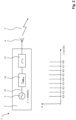
Die
Das empfangene, reflektierte Signal 7 wird nach dem Stand der Technik beispielsweise mittels eines Eingangsverstärkers 10 verstärkt, wobei ein verstärktes, hochfrequentes reflektiertes Signal 22 erzeugt wird, und auf einen Eingang eines Mischers 12 gegeben. An einem zweiten Eingang des Mischers 12 ist ein zweiter Oszillator 11 angeschlossen, welcher eine Mischfrequenz bzw. eine zweite Oszillatorfrequenz 28 erzeugt, mit der der Mischer 12 das verstärkte, hochfrequente reflektierte Signal 22 in eine Zwischenfrequenz 13 umwandelt.According to the prior art, the received reflected
Nachfolgend kann diese Zwischenfrequenz 13 mittels eines ersten Bandfilters 14 gefiltert und in einem Analog-Digital-Wandler 15 in ein digitales Signal gewandelt werden. Das derart bereitgestellte digitale Signal bzw. digitales Zwischenfrequenzsignal 26 wird in einer weiteren in der
Nach diesem Stand der Technik ist es vorgesehen, dass zeitlich nacheinander mehrere verschiedene erste Oszillatorfrequenzen 27 im ersten Oszillator 3 für das Primärsignal 5 erzeugt werden müssen. Es gilt beispielsweise die Beziehung: ![]()
![]()
Nach diesem Stand der Technik ist es ebenfalls vorgesehen, dass zeitlich nacheinander mehrere verschiedene zweite Mischfrequenzen bzw. zweite Oszillatorfrequenzen 28 durch den zweiten Oszillator 11 zur Erzeugung der Zwischenfrequenz 13 im Mischer 12 erzeugt werden müssen, beispielsweise nach der Beziehung: ![]()
![]()
In der
Ein derartiger Frequenzkammgenerator wird mittels eines nichtlinearen elektronischen Bauteils realisiert. Dies erfolgt beispielsweise durch Verwendung einer Step-Recovery Diode, einer nichtlinearen Transmissionsleitung, welche beispielsweise durch eine Leitung mit mindestens zwei Dioden in geeignetem Abstand realisiert werden kann oder durch Ausnutzung von elektrischen Lawineneffekten in Transistoren.Such a frequency comb generator is implemented using a non-linear electronic component. This is done, for example, by using a step-recovery diode, a non-linear transmission line, which can be implemented, for example, by a line with at least two diodes at a suitable distance, or by exploiting electrical avalanche effects in transistors.
Der erste Frequenzkammgenerator 16 stellt an seinem Ausgang ein Primärsignal 5 mit mehreren gleich zueinander beabstandeten Frequenzkomponenten bereit. Das derart erzeugte Primärsignal 5 wird über einen zweiten Bandfilter 17 gefiltert und über die Sendeantenne 4 der Sendeeinheit 2 abgestrahlt.The first
Beispielhaft sind in einem Frequenz-Amplituden-Diagramm mehrere Frequenzkomponenten des erzeugten Ausgangsspektrums des Primärsignals 5 dargestellt, welche äquidistant zueinander angeordnet sind. Das Beispiel der
Der mittels dieser Oszillatorfrequenz 27 f von 100 MHz angesteuerte erste Frequenzkammgenerator 16 stellt in einer Kombination mit dem dritten Bandfilter 19 bzw. Bandpassfilter 19 beispielhaft an seinem Ausgang mehrere äquidistant zueinander beabstandete Frequenzkomponenten an den Stellen 4,0 GHz, 4,1 GHz, 4,2 GHz, 4,3 GHz, 4,4 GHz, 4,5 GHZ, 4,6 GHz, 4,7 GHz und 4,8 GHz bereit. Das derart erzeugte und von der Sendeantenne 4 abgestrahlte Primärsignal 5 beinhaltet somit zeitgleich neun Frequenzkomponenten. Diese neun Frequenzkomponenten werden in der vorliegenden Erfindung innerhalb eines Messzyklus als Primärsignal 5 abgestrahlt. Nach dem Stand der Technik wären hierfür neun Messzyklen notwendig, welche nacheinander ablaufen würden. Somit kann die erfindungsgemäße Radaranordnung die durchzuführenden neun Messungen in einem Neuntel der nach dem Stand der Technik benötigten Messzeit realisieren.The first
Optional kann es vorgesehen sein, dass das mehrere Frequenzkomponenten beinhaltende Signal mittels eines dritten Bandfilters 19 in seiner Bandbreite beschränkt wird, bevor es dem ersten Eingang des zweiten Mischers 20 zugeführt wird.Optionally, it can be provided that the signal containing several frequency components is limited in its bandwidth by means of a
Der zweite Mischer 20 erzeugt an seinem Ausgang ein Mischprodukt bzw. ein Mischsignal 25, welches einem ersten Eingang des ersten Mischers 12 bereitgestellt wird. Auch dieses Mischsignal 25 kann mittels eines vierten Bandfilters 23 in seiner Bandbreite begrenzt werden, bevor sie dem ersten Eingang des ersten Mischers 12 zugeführt wird.The
Ein von einem Objekt oder Ziel 6 reflektiertes hochfrequentes, reflektiertes Signal 7 wird von einer Empfangsantenne 8 empfangen, mittels eines Eingangsverstärkers 10 verstärkt und gelangt als ein verstärktes, hochfrequentes reflektiertes Signal 22 zum zweiten Eingang des ersten Mischers 12.A high-frequency reflected
Im ersten Mischer 12 wird mittels des verstärkten, hochfrequenten reflektierten Signals 22 und dem vom zweiten Mischer 20 erzeugten Mischsignal 25 eine Zwischenfrequenz ZF 13 erzeugt. Die Zwischenfrequenz 13 weist gegenüber dem verstärkten, hochfrequenten reflektierten Signal 22 wesentlich niedrigere Frequenzen auf. In einem Beispiel wäre es denkbar, dass ein Subträger dieser Zwischenfrequenz 13 bei 0 Hz liegen kann. Diese Zwischenfrequenz 13 wird, wie im Stand der Technik üblich, mittels eines Analog-Digital-Wandlers 15 in ein digitales Zwischenfrequenzsignal 26 gewandelt und in einer in der
Optional kann die Zwischenfrequenz 13 mittels eines fünften Bandfilters 24 in seiner Bandbreite begrenzt werden, bevor es vom Analog-Digital-Wandler 15 in ein digitales Zwischenfrequenzsignal 26 umgewandelt wird.Optionally, the
In der in der
Diese unterschiedlichen Abstände der Frequenzkomponenten im Mischsignal 25 sind notwendig, damit sich die einzelnen Frequenzkomponenten im ersten Mischer 12 nicht untrennbar zu einer einzelnen Zwischenfrequenz 13 überlagern, sondern als ein Zwischenfrequenzkamm mit geringem Frequenzabstand der beinhalteten Frequenzkomponenten in diesem Zwischenfrequenzkamm erzeugt werden. Diese Frequenzkomponenten liegen bei der beschriebenen Konstellation bei 0,0005 GHz, 0,0010 GHz, 0,0015 GHz, 0,0020 GHz, 0,0025 GHz, 0,0030 GHz, 0,0035 GHz, 0,0040 GHz.These different spacings of the frequency components in the
Die
In dem gezeigten Frequenz-Amplituden-Diagramm sind beispielhaft acht Frequenzkomponenten des Primärsignals 5 gezeigt. Im Beispiel der
In der
Zur Erzeugung eines Zwischenfrequenzsignals 13 in der Empfangseinheit 9 ist ein spezielles Mischsignal 25 notwendig, welches mittels des zweiten Frequenzkammgenerators 18 und einer Mischung des vom zweiten Frequenzkammgenerators 18 erzeugten Ausgangssignals mit einer dritten Oszillatorfrequenz 29 in einem zweiten Mischer 20 erzeugt wird. Dieses Mischsignal 25 ist nach seiner Filterung im vierten Bandfilter 23 beispielhaft idealisiert in der
Die
Bei der Verarbeitung des empfangenen, reflektierten Signals 7 mit dem Mischsignal 25 in einem ersten Mischer der Empfangseinheit 9 wird das in der
Das Zwischenfrequenzsignal 13 weist in diesem Fall beispielsweise die Frequenzen 0,05 GHz, 0,10 GHz, 0,15 GHz, 0,20 GHz, 0,25 GHz, 0,30 GHz, 0,35 GHz und 0,40 GHz auf.In this case, the
Das derartige Zwischenfrequenzsignal 13 wird zur Bestimmung der Informationen über ein Objekt oder Ziel, wie deren Entfernung, Lage bzw. Winkel, Bewegungsrichtung und Geschwindigkeit und/oder Eigenschaften der Objekte oder Ziele, genutzt.Such
In einer praktischen Umsetzung der Erfindung kann es vorgesehen werden, dass ein zusätzlicher Referenzempfänger angeordnet wird, welcher identisch zu der Empfängereinheit 9, aber ohne Antenne, also mit einer direkten Einkopplung des Primärsignals 5, betrieben wird. Das durch diesen Referenzempfänger erzeugte zwei Empfangssignal, zweite Zwischenfrequenzsignal oder zweite digitale Zwischenfrequenzsignal kann mit dem reflektierten Signal 7 vom Ziel 6, dem Zwischenfrequenzsignal 13 oder dem digitalen Zwischenfrequenzsignal 26 verglichen und zur Verbesserung der Qualität der Signalverarbeitung genutzt werden, wie nach dem Stand der Technik bekannt ist.In a practical implementation of the invention, it can be provided that an additional reference receiver is arranged, which is operated identically to the
Das dieser Beschreibung zugrunde liegende Verfahren kann von einem Fachmann abgewandelt und beispielsweise auch auf Erkennungs- bzw. Ortungsverfahren übertragen werden, welche mit optischen oder akustischen Signalen arbeiten. Derart können beispielsweise zwei oder mehr optische oder akustische Frequenzkomponenten für ein Primärsignal eines Erkennungs- bzw. Ortungsverfahrens erzeugt werden. Eine Einschränkung des nutzbaren Frequenzbereichs auf nur elektromagnetische Wellen im Radiofrequenzbereich ist nicht vorgesehen.The method underlying this description can be modified by a person skilled in the art and, for example, transferred to detection or locating methods that work with optical or acoustic signals. In this way, for example, two or more optical or acoustic frequency components can be generated for a primary signal of a detection or locating method. There is no intention to restrict the usable frequency range to only electromagnetic waves in the radio frequency range.
Claims (12)
- A radar arrangement (1), comprising a transmitting unit (2) with a first oscillator (3) and a transmitting antenna (4), and a receiving unit (9) with a second oscillator (11), a first mixer (12) and a receiving antenna (8), wherein a first frequency comb generator (16) is arranged in the receiving unit (2) between the first oscillator (3) and the transmitting antenna (4),wherein the several frequency components generated by the first frequency comb generator are equidistant to each other, andwherein a second frequency comb generator (18) is arranged in the receiving unit (9) between the second oscillator (11) and the first mixer (12) and generates several frequency components for a mixed signal (25) which equidistant to each other and frequency-shifted relative to the frequency components of the primary signal (5).
- The radar arrangement (1) according to claim 1, characterized in that a second mixer (20) is arranged in the transmitting unit (9) between the second frequency comb generator (18) and the first mixer (12), wherein the second mixer (20) is connected to a third oscillator (21).
- The radar arrangement (1) according to claim 1 or 2, characterized in that a second band filter (17) is arranged in the transmitting unit (2) between the first frequency comb generator (16) and the transmitting antenna (4).
- The radar arrangement (1) according to claim 1 to 3, characterized in that a third band filter (19) is arranged between the second frequency comb generator (18) and the second mixer (20).
- The radar arrangement according to claim 1 to 4, characterized in that a fourth band filter (23) is arranged between the second mixer (20) and the first mixer (12).
- The radar arrangement according to claim 1 to 5, characterized in that an output of the first mixer (12) is connected to an input of an analogue-to-digital converter (15), and in that the analogue-to-digital converter (15) has an output for outputting a digital intermediate frequency signal (26).
- A method for operating a radar arrangement (1), wherein a first oscillator frequency (27) is provided from which a primary signal (5) is generated at least indirectly and emitted via a transmitting antenna (4), and wherein a second oscillator frequency (28) is provided by means of which an intermediate frequency (13) is generated at least indirectly by the mixture of a received, reflected signal (7) with the second oscillator frequency (28), wherein a first frequency comb generator (16) is triggered with the first oscillator frequency (27) on the transmitter side to generate a primary signal (5) containing several frequency components, wherein a second comb generator (18) is triggered with the second oscillator frequency (28) on the receiver side to generate an output signal containing several frequency components, wherein the output signal generated in this way is mixed with a third oscillator frequency (29) and a mixed signal (25) is generated, and wherein the intermediate frequency (13) is generated by the mixture of the received, reflected signal (7) with the mixed signal (25), wherein the several frequency components are generated for the primary signal (5) by the first frequency comb generator (16) on the transmitter side and are equidistant to each other, and wherein the several frequency components are generated for the mixed signal (25) by the second frequency comb generator (18) on the receiver side and are equidistant to each other and frequency-shifted relative to the frequency components of the primary signal (5).
- The method according to claim 7, characterized in that the primary signal (5) generated by the first frequency comb generator (16) is filtered by means of a second band filter (17) before being emitted via a transmitting antenna (4).
- The method according to claim 7 or 8, characterized in that the output signal generated by the second frequency comb generator (18) contains several frequency components and is filtered by means of a third band filter (19) before being mixed with the third oscillator frequency (29).
- The method according to one of the claims 7 to 9, characterized in that the mixed signal (25) is filtered by means of a fourth band filter (23) before being mixed with the received, reflected signal (7).
- The method according to one of the claims 7 to 10, characterized in that the intermediate frequency (13) is converted into a digital intermediate frequency signal (26) by means of an analogue-to-digital converter (15) and is output for further processing or analysis.
- The method according to one of the claims 7 to 11, characterized in that the further processing or analysis of the digital intermediate frequency signal (26) is carried out in the radar arrangement (1), and that information about objects, such as their distance, their position or angle, their direction of movement and speed and/or properties of the objects are determined during this further processing or analysis.
Applications Claiming Priority (2)
| Application Number | Priority Date | Filing Date | Title |
|---|---|---|---|
| DE102018115079.2A DE102018115079B4 (en) | 2018-06-22 | 2018-06-22 | Radar arrangement and method for operating a radar arrangement |
| PCT/DE2019/100436 WO2019242794A1 (en) | 2018-06-22 | 2019-05-14 | Radar assembly and method for operating a radar assembly |
Publications (3)
| Publication Number | Publication Date |
|---|---|
| EP3811103A1 EP3811103A1 (en) | 2021-04-28 |
| EP3811103B1 true EP3811103B1 (en) | 2024-07-10 |
| EP3811103C0 EP3811103C0 (en) | 2024-07-10 |
Family
ID=67003142
Family Applications (1)
| Application Number | Title | Priority Date | Filing Date |
|---|---|---|---|
| EP19732878.4A Active EP3811103B1 (en) | 2018-06-22 | 2019-05-14 | Radar assembly and method for operating a radar assembly |
Country Status (4)
| Country | Link |
|---|---|
| US (1) | US11953583B2 (en) |
| EP (1) | EP3811103B1 (en) |
| DE (2) | DE102018115079B4 (en) |
| WO (1) | WO2019242794A1 (en) |
Family Cites Families (27)
| Publication number | Priority date | Publication date | Assignee | Title |
|---|---|---|---|---|
| US3928851A (en) * | 1960-08-31 | 1975-12-23 | Us Navy | Object locator system |
| US3894293A (en) * | 1963-01-29 | 1975-07-08 | Us Navy | Object locator system with automatic sensitivity reduction for large signals |
| US3939474A (en) * | 1965-09-20 | 1976-02-17 | Rockwell International Corporation | Fully-coherent multiple frequency radar system |
| US3885240A (en) * | 1967-06-27 | 1975-05-20 | Us Navy | Storage radar system |
| US3500303A (en) * | 1968-03-14 | 1970-03-10 | Gen Electric | Signal generator for producing a set of signals of common frequency and adjustable phase slope |
| US3631490A (en) * | 1969-03-17 | 1971-12-28 | Sperry Rand Corp | Signal processor for reducing clutter and eliminating range ambiguities in target detection systems |
| US4504833A (en) * | 1981-12-09 | 1985-03-12 | Xadar Corporation | Synthetic pulse radar system and method |
| US6002707A (en) * | 1983-04-04 | 1999-12-14 | Honeywell, Inc. | Spread signal spectrum communication circuits and system |
| US4983978A (en) * | 1989-03-21 | 1991-01-08 | United Technologies Corporation | Multi-frequency comb generator for radar and the like |
| MY107298A (en) * | 1989-09-18 | 1995-10-31 | Univ Sydney Technology | Random access multiple user communication system. |
| FR2652653B1 (en) * | 1989-09-29 | 1991-12-13 | Centre Nat Rech Scient | VECTOR ANALYZER OF MILLIMETRIC AND / OR SUBMILLIMETRIC NETWORK. |
| US4982165A (en) * | 1989-10-20 | 1991-01-01 | Raytheon Company | Set-on oscillator |
| GB2240240A (en) * | 1990-01-19 | 1991-07-24 | Philips Electronic Associated | Radio receiver for direct sequence spread spectrum signals |
| US5239309A (en) * | 1991-06-27 | 1993-08-24 | Hughes Aircraft Company | Ultra wideband radar employing synthesized short pulses |
| US5146616A (en) * | 1991-06-27 | 1992-09-08 | Hughes Aircraft Company | Ultra wideband radar transmitter employing synthesized short pulses |
| US5729570A (en) * | 1994-12-08 | 1998-03-17 | Stanford Telecommunications, Inc. | Orthogonal code division multiple access communication system having multicarrier modulation |
| US5784403A (en) * | 1995-02-03 | 1998-07-21 | Omnipoint Corporation | Spread spectrum correlation using saw device |
| US5923280A (en) * | 1997-01-17 | 1999-07-13 | Automotive Systems Laboratory, Inc. | Vehicle collision radar with randomized FSK wave form |
| US6085151A (en) * | 1998-01-20 | 2000-07-04 | Automotive Systems Laboratory, Inc. | Predictive collision sensing system |
| US5969667A (en) * | 1997-10-16 | 1999-10-19 | Automotive Systems Laboratory, Inc. | Radar system |
| DE19748608A1 (en) * | 1997-11-04 | 1999-05-06 | Daimler Benz Aerospace Ag | Sampling PLL for high-resolution radar systems |
| AU2107899A (en) * | 1998-01-07 | 1999-07-26 | Cobra Electronics Corp. | Multiple-band radar detector |
| US6570458B2 (en) * | 2001-06-12 | 2003-05-27 | Teradyne, Inc. | Low noise microwave synthesizer employing high frequency combs for tuning drift cancel loop |
| JP5630122B2 (en) * | 2010-07-28 | 2014-11-26 | 富士通株式会社 | Imaging apparatus and transmission / reception apparatus |
| US10018714B2 (en) * | 2015-06-24 | 2018-07-10 | The United States Of America As Represented By The Secretary Of The Army | Two-dimensional RF harmonic imaging system and algorithm |
| CA2932816A1 (en) * | 2016-06-14 | 2017-12-14 | Degelman Industries Ltd. | Land roller |
| US10560110B1 (en) * | 2016-06-28 | 2020-02-11 | Giga-Tronics Incorporated | Precision microwave frequency synthesizer and receiver with delay balanced drift canceling loop |
-
2018
- 2018-06-22 DE DE102018115079.2A patent/DE102018115079B4/en active Active
-
2019
- 2019-05-14 EP EP19732878.4A patent/EP3811103B1/en active Active
- 2019-05-14 DE DE112019003133.3T patent/DE112019003133A5/en not_active Withdrawn
- 2019-05-14 WO PCT/DE2019/100436 patent/WO2019242794A1/en active Application Filing
- 2019-05-14 US US17/253,881 patent/US11953583B2/en active Active
Also Published As
| Publication number | Publication date |
|---|---|
| US11953583B2 (en) | 2024-04-09 |
| EP3811103A1 (en) | 2021-04-28 |
| DE102018115079B4 (en) | 2020-01-30 |
| DE112019003133A5 (en) | 2021-04-08 |
| US20210270953A1 (en) | 2021-09-02 |
| DE102018115079A1 (en) | 2019-12-24 |
| EP3811103C0 (en) | 2024-07-10 |
| WO2019242794A1 (en) | 2019-12-26 |
Similar Documents
| Publication | Publication Date | Title |
|---|---|---|
| EP3418701B1 (en) | Fill level reflectometer with variable measurement sequence | |
| EP2753950B1 (en) | Imaging radar sensor with synthetic enlargement of the antenna aperture and two-dimensional beam sweep | |
| EP2507649B1 (en) | Method for unambiguously determining a range and/or a relative speed of an object, driver assistance device and motor vehicle | |
| DE102014009650A1 (en) | A method and apparatus for detecting the environment based on frequency modulated continuous wave radar | |
| DE102011113018A1 (en) | Imaging radar sensor with narrow antenna lobe and wide angle detection range | |
| DE112006001114T5 (en) | radar | |
| DE102006032540A1 (en) | Angle-resolving radar sensor | |
| DE102015107419A1 (en) | radar device | |
| EP3679391B1 (en) | Fmcw radar sensor having synchronized high-frequency modules | |
| DE102015210676A1 (en) | FMCW RADAR DEVICE AND FMCW RADAR SIGNAL PROCESSING METHOD | |
| DE102019102077A1 (en) | Device for processing a signal from a locating system and method for simulating and locating an object | |
| DE102009047931B4 (en) | Method and device for determining the distance and relative speed of at least one distant object | |
| DE102007042954A1 (en) | Microwave proximity sensor and method for determining the distance between a probe and a target | |
| DE102013216461A1 (en) | Synthetic aperture radar method for remote sensing of surface of earth through radar system, involves generating sub-pulses in respective pulse repetition interval such that sub-pulses have different, non-overlapping frequency ranges | |
| DE2133395C3 (en) | Device to compensate for the proper movement of a coherent impulse Doppler radar system | |
| DE112014006066T5 (en) | Radar device and distance and speed measurement method | |
| WO2020225314A1 (en) | Coherent, multistatic radar system, in particular for use in a vehicle | |
| DE102004062023B4 (en) | Radar system for monitoring targets in different distance ranges | |
| EP3811103B1 (en) | Radar assembly and method for operating a radar assembly | |
| DE102013109279A1 (en) | Radar performance monitoring device has receiver for receiving transmission signal, from which time variation of frequency is non-linear, where transmission signal is transmitted from radar unit of pulse compression radar apparatus | |
| DE102015013389A1 (en) | Method for detecting a fast target by means of a radar system | |
| DE2848625A1 (en) | ARRANGEMENT FOR USE IN AN AIRPLANE TO DETECT OBSTACLES | |
| EP3009858A1 (en) | Cloud radar | |
| EP3064960B1 (en) | Method for operating a permanent line radar detector and permanent line radar detector | |
| DE102011051969B4 (en) | Radar device and method for operating the radar device |
Legal Events
| Date | Code | Title | Description |
|---|---|---|---|
| STAA | Information on the status of an ep patent application or granted ep patent |
Free format text: STATUS: UNKNOWN |
|
| STAA | Information on the status of an ep patent application or granted ep patent |
Free format text: STATUS: THE INTERNATIONAL PUBLICATION HAS BEEN MADE |
|
| STAA | Information on the status of an ep patent application or granted ep patent |
Free format text: STATUS: THE INTERNATIONAL PUBLICATION HAS BEEN MADE |
|
| PUAI | Public reference made under article 153(3) epc to a published international application that has entered the european phase |
Free format text: ORIGINAL CODE: 0009012 |
|
| STAA | Information on the status of an ep patent application or granted ep patent |
Free format text: STATUS: REQUEST FOR EXAMINATION WAS MADE |
|
| 17P | Request for examination filed |
Effective date: 20201210 |
|
| AK | Designated contracting states |
Kind code of ref document: A1 Designated state(s): AL AT BE BG CH CY CZ DE DK EE ES FI FR GB GR HR HU IE IS IT LI LT LU LV MC MK MT NL NO PL PT RO RS SE SI SK SM TR |
|
| AX | Request for extension of the european patent |
Extension state: BA ME |
|
| DAV | Request for validation of the european patent (deleted) | ||
| DAX | Request for extension of the european patent (deleted) | ||
| RAP1 | Party data changed (applicant data changed or rights of an application transferred) |
Owner name: ALTAVO GMBH |
|
| GRAP | Despatch of communication of intention to grant a patent |
Free format text: ORIGINAL CODE: EPIDOSNIGR1 |
|
| STAA | Information on the status of an ep patent application or granted ep patent |
Free format text: STATUS: GRANT OF PATENT IS INTENDED |
|
| INTG | Intention to grant announced |
Effective date: 20240131 |
|
| GRAS | Grant fee paid |
Free format text: ORIGINAL CODE: EPIDOSNIGR3 |
|
| GRAA | (expected) grant |
Free format text: ORIGINAL CODE: 0009210 |
|
| STAA | Information on the status of an ep patent application or granted ep patent |
Free format text: STATUS: THE PATENT HAS BEEN GRANTED |
|
| AK | Designated contracting states |
Kind code of ref document: B1 Designated state(s): AL AT BE BG CH CY CZ DE DK EE ES FI FR GB GR HR HU IE IS IT LI LT LU LV MC MK MT NL NO PL PT RO RS SE SI SK SM TR |
|
| REG | Reference to a national code |
Ref country code: CH Ref legal event code: EP |
|
| REG | Reference to a national code |
Ref country code: DE Ref legal event code: R096 Ref document number: 502019011644 Country of ref document: DE |
|
| U01 | Request for unitary effect filed |
Effective date: 20240810 |