EP3811068B1 - Method and system for detecting a material response - Google Patents
Method and system for detecting a material response Download PDFInfo
- Publication number
- EP3811068B1 EP3811068B1 EP19748887.7A EP19748887A EP3811068B1 EP 3811068 B1 EP3811068 B1 EP 3811068B1 EP 19748887 A EP19748887 A EP 19748887A EP 3811068 B1 EP3811068 B1 EP 3811068B1
- Authority
- EP
- European Patent Office
- Prior art keywords
- magnetic field
- primary
- sample
- atomic magnetometer
- field
- Prior art date
- Legal status (The legal status is an assumption and is not a legal conclusion. Google has not performed a legal analysis and makes no representation as to the accuracy of the status listed.)
- Active
Links
Images


Classifications
-
- G—PHYSICS
- G01—MEASURING; TESTING
- G01N—INVESTIGATING OR ANALYSING MATERIALS BY DETERMINING THEIR CHEMICAL OR PHYSICAL PROPERTIES
- G01N24/00—Investigating or analyzing materials by the use of nuclear magnetic resonance, electron paramagnetic resonance or other spin effects
- G01N24/006—Investigating or analyzing materials by the use of nuclear magnetic resonance, electron paramagnetic resonance or other spin effects using optical pumping
-
- G—PHYSICS
- G01—MEASURING; TESTING
- G01N—INVESTIGATING OR ANALYSING MATERIALS BY DETERMINING THEIR CHEMICAL OR PHYSICAL PROPERTIES
- G01N27/00—Investigating or analysing materials by the use of electric, electrochemical, or magnetic means
- G01N27/72—Investigating or analysing materials by the use of electric, electrochemical, or magnetic means by investigating magnetic variables
- G01N27/82—Investigating or analysing materials by the use of electric, electrochemical, or magnetic means by investigating magnetic variables for investigating the presence of flaws
-
- G—PHYSICS
- G01—MEASURING; TESTING
- G01R—MEASURING ELECTRIC VARIABLES; MEASURING MAGNETIC VARIABLES
- G01R33/00—Arrangements or instruments for measuring magnetic variables
- G01R33/20—Arrangements or instruments for measuring magnetic variables involving magnetic resonance
- G01R33/24—Arrangements or instruments for measuring magnetic variables involving magnetic resonance for measuring direction or magnitude of magnetic fields or magnetic flux
- G01R33/26—Arrangements or instruments for measuring magnetic variables involving magnetic resonance for measuring direction or magnitude of magnetic fields or magnetic flux using optical pumping
Definitions
- the invention relates to method and systems for detecting a material response.
- aspects of the invention seek to provide an improved method and system for detecting a material response.
- a method of detecting a material response including:
- a system for detecting a material response including:
- the method includes detecting changes in electrical conductivity and/or magnetic permeability of the sample from the detection of the secondary magnetic field.
- the magnetic field source is configured to be disposed in a non-overlapping relationship with the sample.
- the system includes a computer including a receiver to receive a signal originating from the atomic magnetometer and representing a detection of the secondary magnetic field, the computer being configured to determine changes in conductivity and/or permeability of the sample in response to detection of the secondary magnetic field.
- a frequency of oscillation of the primary magnetic field is fixed.
- a frequency of modulation of the bias magnetic field is less, preferably by an order of magnitude, than a frequency of oscillation of the primary magnetic field.
- the method includes demodulating a signal, provided by the atomic magnetometer in response to detection of the secondary magnetic field, to determine an amplitude and/or a phase. In some embodiments the method includes demodulating a signal, provided by the atomic magnetometer in response to detection of the secondary magnetic field, with reference to a frequency of oscillation of the primary magnetic field, to provide a partially demodulated signal. In some embodiments the method includes demodulating the partially demodulated signal with reference to a frequency of modulation of the bias magnetic field to determine an amplitude and/or phase of a signal provided by the atomic magnetometer in response to detection of the secondary magnetic field.
- a system for detecting a material response including:
- the system includes a primary magnetic field source for providing an oscillating primary magnetic field.
- the system includes a demodulator arrangement for determining an amplitude and/or phase of a signal, provided by the atomic magnetometer in response to detection of the secondary magnetic field.
- the demodulator arrangement includes a receiver for receiving a signal provided by the atomic magnetometer in response to detection of the secondary magnetic field and is configured to demodulate the signal with reference to a frequency of oscillation of a or the primary magnetic field to provide a partially demodulated signal.
- the demodulator arrangement includes a receiver for receiving a modulation signal from the modulator and is configured to demodulate the partially demodulated signal with reference to the modulation signal to allow determination of an amplitude and/or phase of the partially demodulated signal.
- the bias magnetic field source includes a coil arrangement.
- the material response can be a response of the sample to the primary magnetic field and this may include atomic response, magnetisation, eddy currents, and other responses.
- the secondary magnetic field can be indicative of the material response and in some embodiments the material response can include or be the secondary magnetic field.
- Providing a compensatory magnetic field can include operating a compensation coil arrangement to produce the compensatory magnetic field.
- the method can include varying or tuning one or more distances from a detection cell of the atomic magnetometer of one or more coils of the compensation coil arrangement, so as to reduce the effect on the atomic magnetometer of one or more components of the primary and/or secondary magnetic fields.
- the method can include varying or tuning a distance from the detection cell of a compensation coil having an axis in a direction of that component.
- the compensatory magnetic field is an oscillating magnetic field.
- the compensatory magnetic field is made to oscillate with the same frequency as the primary magnetic field to keep a constant phase difference therebetween.
- Providing an oscillating primary magnetic field substantially orthogonal to the surface of the sample to cause the sample to produce a secondary magnetic field can include operating an rf coil arrangement to provide the primary magnetic field.
- the magnetic field source for providing an oscillating primary magnetic field includes an rf coil with or without a solid core.
- the primary magnetic field is oscillated at an rf frequency, for example in the range 1 Hz to 1 GHz.
- the magnetic field source for providing an oscillating primary magnetic field can be configured to be disposed entirely on one side of a sample surface.
- the system can be configured to be disposed entirely on one side of the sample surface.
- the method and/or system can be for detecting a material response for a variety of purposes, for example for material defects imaging and/or for detecting material electrical conductivity and magnetic permeability.
- the method and/or can be used for corrosion under insulation detection (CUI).
- the method and/or system can be used for detection of the condition of reinforced concrete structures.
- the method and/or system can be used for localisation of objects.
- the atomic magnetometer is a radio-frequency atomic magnetometer.
- the sample has a high magnetic permeability and the secondary magnetic field is dominated by the secondary magnetisation.
- the secondary magnetic field is dominated by the field generated by eddy currents.
- imaging of the structural defects can be realized with radio-frequency atomic magnetometer by recording a material response to the radio-frequency excitation field.
- Described below are two examples of measurement configurations that enable an increase of the amplitude and phase contrast of the images representing a structural defect in paramagnetic and ferromagnetic samples. Both examples involve an elimination of the excitation field component from the atomic magnetometer signal.
- First example is implemented with a set of coils that directly compensates excitation field in magnetometer signal.
- Second example takes advantage of the fact that the radio-frequency magnetometer is not sensitive to the magnetic field oscillating along one of its axis. Results of the modelling that confirm experimental observation are discussed in detail.
- Paper 1 and Paper 2 provide context to the invention and any of the structural or method features, or applications, described in Paper 1 or Paper 2 are applicable to embodiments of the invention, by way of modification or addition.
- Radio-frequency magnetic fields in non-destructive testing provides cost-effective options for detection of structural defects, particularly in cases when there is no direct access to the surface of the studied sample.
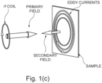
- the technique can involve monitoring the material response to the so-called primary magnetic field ( B ) created by an rf coil [1].
- B primary magnetic field
- the material response can be detected in a variety of ways. Traditionally this is achieved by monitoring the impedance of the rf coil (or a dedicated pickup coil) [1-5].
- the simplicity of instrumentation in this type of measurement is outweighed by signal sensitivity degradation at low frequencies.
- GMR giant magnetoresistance
- SQUIDs superconducting quantum interference devices
- the magnetic field sensors directly monitor the response of the so-called secondary magnetic field ( b ) in the medium.
- the secondary field is produced by the primary magnetic field through eddy currents excited in highly conductive samples, or magnetisation induced in samples with high permeability [15], and contains signatures of the inhomogeneities/ structural defects within the sample.
- Embodiments of the present invention utilise rf atomic magnetometers and can be used for material defects imaging.
- embodiments of the present invention increase the amplitude and/or phase contrast of the output of the system.
- this is achieved by reducing the effect on the atomic magnetometer of components of the primary and secondary magnetic fields in a direction substantially orthogonal to the surface of a sample. This is described below in connection with two embodiments, both of which involve an elimination of the primary and secondary field components in a direction substantially orthogonal to the surface of the sample from the atomic magnetometer signal.
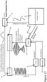
- an embodiment of the invention includes a system 10 including a radio-frequency atomic magnetometer 12 and a primary magnetic field source 14 for providing a primary magnetic field oscillating at rf frequency.
- the primary magnetic field source 14 is an rf coil; however, other magnetic field sources can be used in other embodiments.
- the rf coil 14 is a 1000 turn coil with 0.02 mm wire, wound on a 2 mm plastic core (inside diameter) and with a 4 mm width (outside diameter) and a 10 mm length.
- Samples should be electrically conductive (although not necessarily highly electrically conductive) and/or should have a magnetic permeability such that they can be magnetised.
- the rf coil 14 is configured so that it can be placed adjacent to a sample 16, but entirely on one side thereof and in a non-overlapping relationship therewith, and can be operated to generate an oscillating primary magnetic field to cause the sample to produce a secondary magnetic field.
- the secondary magnetic field is indicative of a material response of the sample.
- the atomic magnetometer is configured to detect the secondary magnetic field.
- Figure 1(a) shows the main components of an experimental setup.
- secondary magnetic field is produced by eddy currents excited in a sample (in this case an Al plate with recess having a 48 mm diameter and a 2.4 mm depth) by primary field created by the rf coil.
- Atomic magnetometer signal would normally combine components created by primary field generated by rf coil and secondary magnetic field.
- the z direction is the direction orthogonal to the surface of the sample
- the x and y directions are mutually orthogonal directions that are parallel to the surface of the sample.
- the magnetometer includes a bias magnetic field source 24 (not shown in Figure 1(a) ) configured to provide a bias magnetic field 26 at the detection cell 20 in a bias magnetic field direction.
- the magnetometer To perform active compensation of the ambient field and any residual DC magnetic field created by the sample, the magnetometer includes a fluxgate 25 located next to the vapour cell 20 and three PID units (in this embodiment SRS 960).
- the fluxgate is Bartington Mag690.
- the linewidth of the rf spectral profile is approximately 30 Hz.
- the small size of the detection cell 20 can provide partial immunity to ambient field gradients.
- the atomic magnetometer includes a probe laser 30 configured to probe atomic spin precession in the detection cell 20 with a linearly polarised probe laser beam 32 phase-offset-locked to the pump beam and orthogonal to the bias magnetic field 26.
- the atomic magnetometer includes a balanced polarimeter 34 configured to receive the probe laser beam after passing through the detection cell 20 and detect Faraday rotation.
- the balanced polarimeter is configured to provide an electronic output signal representing the Faraday rotation detection.
- the rf coil 14 axis is orthogonal to both the pump and probe beam.
- the system 10 includes a primary field oscillation controller in the form of a lock-in amplifier 36 (not shown in Figure 1(a) ) configured to operate the rf coil 14 by providing current therein oscillating at an rf frequency to generate the primary magnetic field and to control the frequency and phase of the current in the rf coil 14 and thereby also of the primary magnetic field, and includes a receiver to receive the output signal from the balanced polarimeter of the atomic magnetometer.
- the lock-in amplifier 36 may be configured to provide frequency modulated current in the rf coil to provide a frequency modulated primary magnetic field, although this is not necessary in every embodiment.
- the lock-in amplifier is configured to demodulate the output signal from the balanced polarimeter with reference to the current frequency or modulation of the rf coil 14, and to provide a first output signal for example to a computer to obtain an amplitude and/or phase of the signal.
- the lock-in amplifier thereby serves as a demodulator.
- the computer can use the amplitude of the signal to detect a material response of the sample, and in some cases to perform material defects imaging.
- the computer can include a receiver to receive the first output signal from the lock-in amplifier 36 and to determine therefrom changes in conductivity and/or permeability of the sample.
- This embodiment uses a magnetically unshielded environment where static fields along y and z directions are nulled and a bias field along the x direction is created by three pairs of mutually orthogonal nested square Helmholtz coils [18] with dimensions 1 m, 0.94 m and 0.88 m respectively (largest coil length 1 m)
- the Helmholtz coils form a coil arrangement for active and passive compensation of the ambient magnetic field, for lowering noises, and for stabilising and adjusting the direction and strength of the bias magnetic field.
- the coil arrangement provides the bias magnetic field source.
- the measurement signal comes from the phase and amplitude change in the rf resonance spectra registered by the rf atomic magnetometer as a sample is moved under the rf coil ( Fig. 1(a) ).
- the rf coil producing B is driven by the output of the internal reference of the lock-in amplifier 36.
- the samples are fixed to a 2D, computer controlled translation stage.
- the sample 16 is located approximately 30 cm from the cell and the coil is placed 1 mm - 2 mm above the sample surface on the same axis as the cell.
- the strength of the bias field ( B blas ) defines the operating frequency of the system (12.6 kHz in this embodiment, although other frequencies can be used, for example in the range 10 kHz - 20 kHz), in other words the frequency of the magnetic resonance and the required primary field frequency.
- Coherent spin precession of the Cs atoms is coupled to the polarisation of the probe beam (Faraday rotation) which is detected with the balanced polarimeter, whose signal is then processed by the lock-in amplifier 36 referenced to the phase of the rf field.
- this can be performed for each pixel of the sample surface, as the sample or system is moved.
- the particular atomic magnetometer described above is not the only type of atomic magnetometer that can be used; for example, different detection cells, different dimensions, different powers, different laser frequencies, and different transitions can be employed as appropriate.
- atoms other than Cs atoms can be used in solid state, liquid, and/or vapour form, and the frequencies and powers can be adjusted accordingly.
- the means of pumping, field generation, translation and probe beam detection can be varied.
- the pump and probe subsystem can use one, two, three, or more lasers to perform the pumping and probing, and the polarisations of the beams can be varied in some embodiments.
- the balanced polarimeter can be replaced with any probe beam detector which is preferably a photodetector that can detect the polarisation and/or amplitude of the probe beam.
- the inventors have previously analysed the shape of the spatial profiles generated by the recess in aluminium plates [15].
- the profile represents variations in phase and amplitude of the rf spectroscopy signal recorded by the atomic magnetometer. It contains contributions from the primary and secondary magnetic field.
- a strong primary field contribution in the magnetometer signal results in the mapping of two orthogonal components of the secondary field, b z and b y , onto the amplitude and phase of the rf spectroscopy signal respectively.
- the inventors have noted that the component of the secondary field, b y , parallel to the sample surface changes its sign in the vicinity of the surface crack (recess).
- variations in the resultant field recorded by the rf atomic magnetometer measure the direction flip of the secondary field component, however the observed rf signal phase change is smaller than actual change in b y .
- the system includes a compensatory magnetic field source 40 for providing an oscillating compensatory magnetic field, also called a compensation magnetic field, at the atomic magnetometer, specifically at the detection cell 20, including a component substantially orthogonal to the surface of the sample 16 reducing and preferably eliminating the effect on the atomic magnetometer of magnetic field components of the primary and secondary fields in that direction.
- the compensatory magnetic field compensates the primary field contribution to the resultant field monitored by the atomic magnetometer vapour cell, without changing efficiency of b excitation.
- the compensatory magnetic field source 40 is a compensation coil arrangement including a first compensation coil 42 and a second compensation coil 44.
- the first compensation coil 42 has an axis substantially aligned with z, a direction orthogonal to the surface of the sample 16 so as to provide a magnetic field at the atomic magnetometer, specifically at the detection cell 20, which is substantially orthogonal to the surface of the sample 16.
- the detection cell 20 is located between the rf coil 14 and the first compensation coil 42, although this is not necessary in all embodiments.
- the second compensation coil 44 has an axis substantially aligned with y, a direction parallel to the surface of the sample 16 and substantially orthogonal to the bias field direction so as to provide a magnetic field at the atomic magnetometer, specifically at the detection cell 20 which is substantially parallel to the surface of the sample 16 and substantially orthogonal to the bias field direction.
- the detection cell 20 is located between the probe laser 30 and the second compensation coil 44, and the second compensation coil 44 is located between the detection cell 20 and the balanced polarimeter 34, although this is not necessary in all embodiments.
- the compensatory coil arrangement 40 is configured to provide, at the detection cell 20, a compensatory magnetic field B c .
- a set of two rf coils oriented along z and y directions creates an oscillating magnetic field, B c , that compensates the primary field seen by the atomic magnetometer.
- the coils are driven by the output of the internal reference of the same lock-in amplifier 36 used to generate B . This keeps a constant phase difference between the fields B and B c .
- the primary field is compensated in vapour cell by a set of two rf coils oriented along z and y direction.
- the amplitudes of the two components of B c can be varied by changing the distance of the relevant coils from the vapour cell.
- the configuration allows determination of amplitude and phase (orientation) of the rf in yz plane.
- Figure 3 shows the simulated dependence of the amplitude and phase of the rf spectroscopy signal measured by the atomic magnetometer on the resultant magnetic field.
- This indicates that the condition for achieving maximum contrast, with respect to the ⁇ axis components, is when B' z + b z,max 0.
- B' y 0, as the compensation point.
- the inventors adapted as a testbed for the experimental exploration of rf magnetic field compensation, changes in the amplitude and phase of the rf spectroscopy signal recorded with an rf coil scanned across a defect in the form of a recess (24.5 mm diameter, 2.4 mm deep) in 6 mm thick aluminium and carbon steel plate [15].
- this is achieved by tuning the distance between the compensation coils and the vapour cell 20 ( Fig. 1(a) ).
- the coil located above the vapour cell 20 (the first compensation coil 42) is positioned on axes with the rf coil 14 producing the primary field.
- the optimum location of this coil along z is established by minimising the amplitude of the rf spectroscopy signal.
- the position of the other compensation coil (the second compensation coil 44) can be adjusted in all three directions.
- the presence of this coil is particularly important in measurements with ferromagnetic objects, where a significant rf field is produced in the plane parallel to the sample surface (the horizontal plane in this instance) by the sample.
- Figure 3 indicates that compensation in the horizontal direction results in symmetric amplitude and phase profiles. This factor is utilised in searches for the compensation point.
- Figure 4 shows the changes in (a) amplitude, C R (blue diamonds), and (b) phase, C ⁇ , contrast as a function of the distance of the vertical coil from the compensation point along z.
- the measurement has been performed with a 6 mm thick aluminium plate.
- Green squares in Fig. 4 (a) represent the change of the rf spectroscopy signal measured in the centre of the recess. Both plots confirm the presence of the maximum contrast at the compensation point.
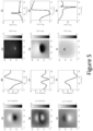
- Figure 5 (a)-(c)/ (g)-(i) shows the amplitude/ phase images of 64 ⁇ 64mm 2 area of a 6mm thick carbon steel plate containing a 24.5mm diameter recess that is 2.4mm deep recorded for three values of the horizontal component of the compensation rf field.
- the vertical cross-sections through the centre of the amplitude/ phase images are shown in Fig. 5 (d)-(f)/ (j)-(l). They are equivalent to the calculated amplitude profiles from the second row of Fig. 3 .
- the cases illustrated in Fig. 5 (b)/(e), ((h)/ (k) represent the compensation point. Near the compensation point, the amplitude image produced by a recess is symmetrical, i.e. two maxima corresponding to rising and falling edges.
- [[Fig. 5 (e)]] to R
- phase contrast decreases as we move away from the compensation point, Fig. 5 (g)-(i).
- area where the phase departs from its background value decreases away from the compensation point. This might have practical consequences in a measurement with a coarse spatial step, since the phase change generated by the recess could be non-visible as it would be equivalent to spatial integration of the phase change over a larger area.
- rf compensation can be demonstrated in the experiment with increased lift-off distance, 6 mm - 7 mm.
- Starting point for this is a measurement of the phase contrast in a standard configuration (the rf coil producing the primary field located 1 mm - 2 mm above the sample surface, no rf compensation).
- An increase of the lift off (6 mm - 7 mm) results in a reduction of the strength of the primary at the sample, and consequently, secondary field.
- B c has components in direction y as well as z, this is not necessary in every embodiment. For example, it is possible to compensate only in the z direction. In the above embodiment, this means that the second compensation coil 44 can be omitted.
- Figure 6 Another embodiment is shown in Figure 6 .
- the effect on the atomic magnetometer of components of the primary and secondary fields in a direction substantially orthogonal to the surface of the sample is reduced by aligning an insensitive axis of the atomic magnetometer with a direction substantially orthogonal to the surface of the sample.
- the method of this embodiment benefits from fact that the rf atomic magnetometer is not sensitive to magnetic field oscillating along static bias field axes, B blas ( Fig. 1(a) ) [16].
- B blas Fig. 1(a)
- B z will be absent in the rf atomic magnetometer signal and the measurement configuration becomes equivalent to one with the compensated primary field component.
- Static bias magnetic field 26 is directed along z and set to the same strength used in previous measurements (equivalent to Larmor frequency about 12.6 kHz).
- the pump laser beam 28 is aligned along bias magnetic field 26.
- the Helmholtz coils are adjusted accordingly and configured to null static fields along x and y directions.
- the system also includes a set of rf coils 40' for providing a compensatory magnetic field for compensating for components of the primary field which are parallel to the sample surface (horizontal components of the primary field in this instance).
- the position of these compensating coils are varied such that the rf spectroscopy signal is minimised.
- the compensating coils 40' include a first compensation coil 46 and the second compensation coil 44, the second compensation coil 44 being as discussed above.
- the first compensation coil 46 has an axis substantially parallel to the sample surface and substantially orthogonal to the bias field direction and the direction of the probe laser. In this embodiment, the axis of the first compensation coil 46 is substantially aligned with direction x.
- the embodiment of Figure 6 has B blas along z .
- the pump laser beams orients atomic vapour along direction of the bias field.
- Horizontal components of the primary field is compensated in vapour cell by a set of two rf coils oriented along x and y direction.
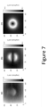
- Figure 7 illustrates benefits of and differences between two discussed compensation schemes. It shows the images of 64 ⁇ 64 mm 2 area of a 6 mm thick Al plate containing a 24 mm diameter recess that is 2.4 mm deep recorded in three different configurations: (a) without compensation, (b) with compensation performed with two rf coils, and (c) with rotated bias magnetic field and compensation coils. Images represent the change of the amplitude of the rf spectroscopy signal. As mentioned before, for the uncompensated case (a) the recorded profile shows variation of the vertical component of the secondary field. In compensated cases the images show horizontal component (b)/ components (c) of the secondary field. The difference in symmetry of the image results from the change of the direction of the bias field. In case shown in Fig.
- B blas is directed along x axis and therefore only signatures produced by the recess edges parallel to that direction are present in the recorded profile (in other words, the edge parallel to B blas produces oscillating secondary field perpendicular to B blas that could be seen by the magnetometer).
- B blas is directed along z axis and the recorded profile shows whole contour of the recess.
- the phase of the rf spectroscopy signal shows a vortex centered on the recess.
- the bias magnetic field is modulated. This can be in addition to or instead of reducing the effect on the magnetometer of components of the primary and secondary magnetic fields in a direction substantially orthogonal to the sample. In other respects, the embodiment is substantially as described for the first or second embodiments.
- Figure 8 shows a schematic system diagram of the system of Figures 1(a) and 6 .
- the system works in the following way.
- the frequency of the primary field is scanned across rf resonance, i.e. the whole resonance profile is recorded, for each point of the image [15].
- the inventors have developed another mode of data aquisition, which enables significant decrease in image acquisition time.
- the modulation of the B frequency is replaced with the low-frequency modulation (1-20 Hz in this example) of the amplitude of the B blas component.
- the signal demodulated at the primary field frequency by the lock-in amplifier 36 contains low-frequency oscillation with the amplitude equal to this of the rf resonance amplitude.
- second lock-in amplifier referenced to the frequency of the B blas amplitude modulation enables readout of the rf resonance amplitude.
- the extent of the B frequency modulation can balance an imperfection in the B blas stabilisations such as a possible shift in resonance frequency for different sample locations.
- the phase of the recorded signal contains information about the change of the secondary field as well the rf profile frequency shift.
- the system includes the second lock-in amplifier 38.
- the bias magnetic field source 24 includes a modulator to modulate the bias magnetic field and to output a modulation signal to the second lock-in amplifier 38.
- the first output of the first lock-in amplifier (referenced to rf coil frequency) is connected to the input of the second lock-in amplifier (referenced to the bias field modulation).
- the second lock-in amplifier is configured to demodulate the output signal from the first lock-in amplifier 36 with reference to the modulation of the bias magnetic field and to provide an amplitude and phase of the signal.
- the second lock-in amplifier 38 thereby serves as a demodulator.
- the method is as follows:
- Embodiments for example such as any of the systems described above, can perform imaging with a sensitivity of 0.1 mm.
- Embodiments can be used to image steelwork non-destructively in the presence of concealing conductive barriers at room temperature, in magnetically unscreened environments, with active compensation of the background fields, and compensation of the samples' magnetisation. This can be used for example for detection of corrosion in concealed pipes (CUI) and detection of structural anomalies in concrete structures.
- Embodiments of the invention can be used for detecting corrosion under insulation.
- Embodiments of the invention can provide increased contrast to enable the imaging of sub-mm corrosion pits for example in pipes.
- the systems described above can be deployed on a robot to scan large areas for example of pipeline.
- the method and/or system can be used for detection of the condition of concrete structures.
- Applications can be in manufacturing and construction, where quality of assemblies and welding is important, and often requires the use of potentially dangerous and expensive X-ray scans; materials manufacturing as part of a fabrication process; health and usage monitoring systems (HUMS), where timely and non-invasive identification of structural damages and fatigue is a primary target; nuclear; and in the utilities and/or energy sector, for example oil and gas, where spillage has economical as well as environmental costs.
- Applications also include detecting corrosion under insulation for energy sector, monitoring of the re-enforced concrete structures for transport sector, nuclear waste vessels monitoring.
- a lock-in amplifier 36 is described as providing the primary field controller
- the primary field controller can include any current generator provided that the primary field oscillation controller includes a processor for demodulating the output signal from the balanced polarimeter with reference to the frequency or modulation of the current generator.
- a lock-in amplifier is advantageous because they make the detection of the spectra easier as the source of the frequency/modulation and detector are inside one instrument (synchronisation, referencing, is automatically sorted out).
- the material response detection is used for material defects imaging, this is not necessary in every embodiment.
- the material response detection can be used for other purposes, for example to detect material conductivity and/or permeability.
Landscapes
- Physics & Mathematics (AREA)
- Chemical & Material Sciences (AREA)
- General Physics & Mathematics (AREA)
- General Health & Medical Sciences (AREA)
- Immunology (AREA)
- Life Sciences & Earth Sciences (AREA)
- Analytical Chemistry (AREA)
- Biochemistry (AREA)
- Pathology (AREA)
- Health & Medical Sciences (AREA)
- Chemical Kinetics & Catalysis (AREA)
- Electrochemistry (AREA)
- Optics & Photonics (AREA)
- High Energy & Nuclear Physics (AREA)
- Condensed Matter Physics & Semiconductors (AREA)
- Investigating Or Analyzing Materials By The Use Of Magnetic Means (AREA)
- Measuring Magnetic Variables (AREA)
Applications Claiming Priority (3)
| Application Number | Priority Date | Filing Date | Title |
|---|---|---|---|
| GB1811928.9A GB2575695B (en) | 2018-07-20 | 2018-07-20 | Method and system for detecting a material response |
| GBGB1813858.6A GB201813858D0 (en) | 2018-08-24 | 2018-08-24 | Method and system for detecting a material response |
| PCT/GB2019/051953 WO2020016557A1 (en) | 2018-07-20 | 2019-07-11 | Method and system for detecting a material response |
Publications (3)
| Publication Number | Publication Date |
|---|---|
| EP3811068A1 EP3811068A1 (en) | 2021-04-28 |
| EP3811068C0 EP3811068C0 (en) | 2024-09-25 |
| EP3811068B1 true EP3811068B1 (en) | 2024-09-25 |
Family
ID=67515015
Family Applications (1)
| Application Number | Title | Priority Date | Filing Date |
|---|---|---|---|
| EP19748887.7A Active EP3811068B1 (en) | 2018-07-20 | 2019-07-11 | Method and system for detecting a material response |
Country Status (6)
| Country | Link |
|---|---|
| US (1) | US11747302B2 (https=) |
| EP (1) | EP3811068B1 (https=) |
| JP (1) | JP7525117B2 (https=) |
| CN (1) | CN112513623B (https=) |
| ES (1) | ES2992289T3 (https=) |
| WO (1) | WO2020016557A1 (https=) |
Families Citing this family (4)
| Publication number | Priority date | Publication date | Assignee | Title |
|---|---|---|---|---|
| GB2585851B (en) | 2019-07-17 | 2021-08-25 | Npl Management Ltd | Atomic magnetometer system |
| GB2588114B (en) | 2019-10-07 | 2022-04-13 | Npl Management Ltd | Method and system for generation of atomic spin orientation |
| US11486945B1 (en) * | 2022-07-05 | 2022-11-01 | Zhejiang University Of Science And Technology | Device and method for measuring scalar magnetic field based on pulsed optical pumping |
| CN115754834B (zh) * | 2022-10-24 | 2026-02-03 | 浙江科技学院 | 可用于涡流测量的稳定原子射频磁力仪 |
Family Cites Families (20)
| Publication number | Priority date | Publication date | Assignee | Title |
|---|---|---|---|---|
| US7038450B2 (en) * | 2002-10-16 | 2006-05-02 | Trustees Of Princeton University | High sensitivity atomic magnetometer and methods for using same |
| US7340712B2 (en) * | 2005-06-01 | 2008-03-04 | International Business Machines Corporation | System and method for creating a standard cell library for reduced leakage and improved performance |
| US7521928B2 (en) | 2006-11-07 | 2009-04-21 | Trustees Of Princeton University | Subfemtotesla radio-frequency atomic magnetometer for nuclear quadrupole resonance detection |
| CN101553503B (zh) * | 2006-12-22 | 2012-11-07 | 弗·哈夫曼-拉罗切有限公司 | α-1,6-岩藻糖基转移酶表达的SHRNA介导的抑制 |
| WO2009079054A2 (en) * | 2007-09-21 | 2009-06-25 | The Regents Of The University Of California | Radio frequency atomic magnetometer |
| JP5707021B2 (ja) * | 2008-09-30 | 2015-04-22 | 株式会社日立ハイテクノロジーズ | 磁場計測装置 |
| JP5223794B2 (ja) * | 2009-06-26 | 2013-06-26 | セイコーエプソン株式会社 | 磁気センサー |
| US8212556B1 (en) * | 2010-01-12 | 2012-07-03 | Sandia Corporation | Atomic magnetometer |
| US8970217B1 (en) | 2010-04-14 | 2015-03-03 | Hypres, Inc. | System and method for noise reduction in magnetic resonance imaging |
| KR101206727B1 (ko) * | 2011-01-03 | 2012-11-30 | 한국표준과학연구원 | 저자기장 핵자기공명 장치 및 저자기장 핵자기공명 방법 |
| KR101287426B1 (ko) * | 2011-10-26 | 2013-07-18 | 한국표준과학연구원 | 극저자기장 핵자기 공명 물체 식별 방법 및 극저자기장 핵자기 공명 물체 식별 장치 |
| WO2014031985A1 (en) * | 2012-08-24 | 2014-02-27 | The Trustees Of Dartmouth College | Method and apparatus for magnetic susceptibility tomography, magnetoencephalography, and taggant or contrast agent detection |
| US9857441B2 (en) * | 2013-06-20 | 2018-01-02 | Honeywell International Inc. | Single beam radio frequency atomic magnetometer |
| FR3008190B1 (fr) * | 2013-07-08 | 2015-08-07 | Commissariat Energie Atomique | Procede et dispositif de mesure d'un champ magnetique au moyen d'excitations synchronisees |
| JP2015121409A (ja) | 2013-12-20 | 2015-07-02 | 株式会社東芝 | 埋設管検査装置及び埋設管検査方法 |
| US9995800B1 (en) * | 2014-04-29 | 2018-06-12 | National Technology & Engineering Solutions Of Sandia, Llc | Atomic magnetometer with multiple spatial channels |
| JP6529230B2 (ja) * | 2014-08-28 | 2019-06-12 | ニッカ電測株式会社 | 金属検出装置 |
| KR101624482B1 (ko) * | 2014-10-24 | 2016-05-26 | 한국표준과학연구원 | 원자 자력계 및 그 동작 방법 |
| JP2017026402A (ja) * | 2015-07-21 | 2017-02-02 | キヤノン株式会社 | 光ポンピング磁力計及び磁気センシング方法 |
| CN106842074B (zh) * | 2017-03-03 | 2019-07-02 | 中国人民解放军国防科学技术大学 | 基于纵向磁场调制的三轴矢量原子磁力仪及使用方法 |
-
2019
- 2019-07-11 EP EP19748887.7A patent/EP3811068B1/en active Active
- 2019-07-11 CN CN201980047140.5A patent/CN112513623B/zh active Active
- 2019-07-11 US US17/261,336 patent/US11747302B2/en active Active
- 2019-07-11 JP JP2021503003A patent/JP7525117B2/ja active Active
- 2019-07-11 ES ES19748887T patent/ES2992289T3/es active Active
- 2019-07-11 WO PCT/GB2019/051953 patent/WO2020016557A1/en not_active Ceased
Also Published As
| Publication number | Publication date |
|---|---|
| JP7525117B2 (ja) | 2024-07-30 |
| US20210278371A1 (en) | 2021-09-09 |
| JP2021530709A (ja) | 2021-11-11 |
| ES2992289T3 (es) | 2024-12-11 |
| CN112513623B (zh) | 2023-03-28 |
| EP3811068A1 (en) | 2021-04-28 |
| CN112513623A (zh) | 2021-03-16 |
| EP3811068C0 (en) | 2024-09-25 |
| US11747302B2 (en) | 2023-09-05 |
| WO2020016557A1 (en) | 2020-01-23 |
Similar Documents
| Publication | Publication Date | Title |
|---|---|---|
| Bevington et al. | Enhanced material defect imaging with a radio-frequency atomic magnetometer | |
| EP3811068B1 (en) | Method and system for detecting a material response | |
| Tsukada et al. | Small eddy current testing sensor probe using a tunneling magnetoresistance sensor to detect cracks in steel structures | |
| US20230400534A1 (en) | Sensor using a field gradient in a given volume | |
| Nair et al. | A GMR-based eddy current system for NDE of aircraft structures | |
| Bevington et al. | Non-destructive structural imaging of steelwork with atomic magnetometers | |
| GB2575695A (en) | Method and system for detecting a material response | |
| US20020130659A1 (en) | Magnetoresistive flux focusing eddy current flaw detection | |
| EP3999839B1 (en) | Atomic magnetometer system | |
| Bevington et al. | Imaging of material defects with a radio-frequency atomic magnetometer | |
| US9274085B2 (en) | Eddy current inspection device, eddy current inspection probe, and eddy current inspection method | |
| Zhou et al. | Imaging damage in steel using a diamond magnetometer | |
| JP2021530709A5 (https=) | ||
| Wang et al. | Multi-frequency imaging with non-linear calibration of magnetoresistance sensors for surface and buried defects inspection | |
| US20210072187A1 (en) | Non-destructive inspection device | |
| KR101929240B1 (ko) | 웨이퍼 검사장치 | |
| Rushton et al. | Polarization of radio-frequency magnetic fields in magnetic induction measurements with an atomic magnetometer | |
| US7365533B2 (en) | Magneto-optic remote sensor for angular rotation, linear displacements, and evaluation of surface deformations | |
| JPWO2020016557A5 (https=) | ||
| CN110456419A (zh) | 一种电磁激励响应信号互感装置和检测装置及检测方法 | |
| US20240036003A1 (en) | Method and System for Material Identification Using Magnetic Induction Tomography | |
| Hasan et al. | Quantum Magnetometers for Infrastructure Inspection and Monitoring | |
| Vindolet et al. | Diamond quantum sensors for non-destructive testing | |
| Capova et al. | Recent trends in electromagnetic non-destructive sensing | |
| Lee et al. | AC Modulated Magneto‐Optic Sensor for Remote Investigation of Surface Deformation |
Legal Events
| Date | Code | Title | Description |
|---|---|---|---|
| STAA | Information on the status of an ep patent application or granted ep patent |
Free format text: STATUS: UNKNOWN |
|
| STAA | Information on the status of an ep patent application or granted ep patent |
Free format text: STATUS: THE INTERNATIONAL PUBLICATION HAS BEEN MADE |
|
| PUAI | Public reference made under article 153(3) epc to a published international application that has entered the european phase |
Free format text: ORIGINAL CODE: 0009012 |
|
| STAA | Information on the status of an ep patent application or granted ep patent |
Free format text: STATUS: REQUEST FOR EXAMINATION WAS MADE |
|
| 17P | Request for examination filed |
Effective date: 20210119 |
|
| AK | Designated contracting states |
Kind code of ref document: A1 Designated state(s): AL AT BE BG CH CY CZ DE DK EE ES FI FR GB GR HR HU IE IS IT LI LT LU LV MC MK MT NL NO PL PT RO RS SE SI SK SM TR |
|
| AX | Request for extension of the european patent |
Extension state: BA ME |
|
| DAV | Request for validation of the european patent (deleted) | ||
| DAX | Request for extension of the european patent (deleted) | ||
| STAA | Information on the status of an ep patent application or granted ep patent |
Free format text: STATUS: EXAMINATION IS IN PROGRESS |
|
| 17Q | First examination report despatched |
Effective date: 20220810 |
|
| GRAP | Despatch of communication of intention to grant a patent |
Free format text: ORIGINAL CODE: EPIDOSNIGR1 |
|
| STAA | Information on the status of an ep patent application or granted ep patent |
Free format text: STATUS: GRANT OF PATENT IS INTENDED |
|
| RIC1 | Information provided on ipc code assigned before grant |
Ipc: G01N 27/82 20060101ALI20240308BHEP Ipc: G01R 33/26 20060101ALI20240308BHEP Ipc: G01N 24/00 20060101AFI20240308BHEP |
|
| INTG | Intention to grant announced |
Effective date: 20240415 |
|
| GRAS | Grant fee paid |
Free format text: ORIGINAL CODE: EPIDOSNIGR3 |
|
| GRAA | (expected) grant |
Free format text: ORIGINAL CODE: 0009210 |
|
| STAA | Information on the status of an ep patent application or granted ep patent |
Free format text: STATUS: THE PATENT HAS BEEN GRANTED |
|
| AK | Designated contracting states |
Kind code of ref document: B1 Designated state(s): AL AT BE BG CH CY CZ DE DK EE ES FI FR GB GR HR HU IE IS IT LI LT LU LV MC MK MT NL NO PL PT RO RS SE SI SK SM TR |
|
| REG | Reference to a national code |
Ref country code: GB Ref legal event code: FG4D |
|
| REG | Reference to a national code |
Ref country code: CH Ref legal event code: EP |
|
| REG | Reference to a national code |
Ref country code: DE Ref legal event code: R096 Ref document number: 602019059439 Country of ref document: DE |
|
| REG | Reference to a national code |
Ref country code: IE Ref legal event code: FG4D |
|
| U01 | Request for unitary effect filed |
Effective date: 20241016 |
|
| U07 | Unitary effect registered |
Designated state(s): AT BE BG DE DK EE FI FR IT LT LU LV MT NL PT RO SE SI Effective date: 20241104 |
|
| REG | Reference to a national code |
Ref country code: ES Ref legal event code: FG2A Ref document number: 2992289 Country of ref document: ES Kind code of ref document: T3 Effective date: 20241211 |
|
| PG25 | Lapsed in a contracting state [announced via postgrant information from national office to epo] |
Ref country code: NO Free format text: LAPSE BECAUSE OF FAILURE TO SUBMIT A TRANSLATION OF THE DESCRIPTION OR TO PAY THE FEE WITHIN THE PRESCRIBED TIME-LIMIT Effective date: 20241225 |
|
| PG25 | Lapsed in a contracting state [announced via postgrant information from national office to epo] |
Ref country code: GR Free format text: LAPSE BECAUSE OF FAILURE TO SUBMIT A TRANSLATION OF THE DESCRIPTION OR TO PAY THE FEE WITHIN THE PRESCRIBED TIME-LIMIT Effective date: 20241226 |
|
| PG25 | Lapsed in a contracting state [announced via postgrant information from national office to epo] |
Ref country code: RS Free format text: LAPSE BECAUSE OF FAILURE TO SUBMIT A TRANSLATION OF THE DESCRIPTION OR TO PAY THE FEE WITHIN THE PRESCRIBED TIME-LIMIT Effective date: 20241225 |
|
| PG25 | Lapsed in a contracting state [announced via postgrant information from national office to epo] |
Ref country code: RS Free format text: LAPSE BECAUSE OF FAILURE TO SUBMIT A TRANSLATION OF THE DESCRIPTION OR TO PAY THE FEE WITHIN THE PRESCRIBED TIME-LIMIT Effective date: 20241225 Ref country code: NO Free format text: LAPSE BECAUSE OF FAILURE TO SUBMIT A TRANSLATION OF THE DESCRIPTION OR TO PAY THE FEE WITHIN THE PRESCRIBED TIME-LIMIT Effective date: 20241225 Ref country code: GR Free format text: LAPSE BECAUSE OF FAILURE TO SUBMIT A TRANSLATION OF THE DESCRIPTION OR TO PAY THE FEE WITHIN THE PRESCRIBED TIME-LIMIT Effective date: 20241226 |
|
| PG25 | Lapsed in a contracting state [announced via postgrant information from national office to epo] |
Ref country code: IS Free format text: LAPSE BECAUSE OF FAILURE TO SUBMIT A TRANSLATION OF THE DESCRIPTION OR TO PAY THE FEE WITHIN THE PRESCRIBED TIME-LIMIT Effective date: 20250125 |
|
| PG25 | Lapsed in a contracting state [announced via postgrant information from national office to epo] |
Ref country code: SM Free format text: LAPSE BECAUSE OF FAILURE TO SUBMIT A TRANSLATION OF THE DESCRIPTION OR TO PAY THE FEE WITHIN THE PRESCRIBED TIME-LIMIT Effective date: 20240925 |
|
| PG25 | Lapsed in a contracting state [announced via postgrant information from national office to epo] |
Ref country code: PL Free format text: LAPSE BECAUSE OF FAILURE TO SUBMIT A TRANSLATION OF THE DESCRIPTION OR TO PAY THE FEE WITHIN THE PRESCRIBED TIME-LIMIT Effective date: 20240925 Ref country code: CZ Free format text: LAPSE BECAUSE OF FAILURE TO SUBMIT A TRANSLATION OF THE DESCRIPTION OR TO PAY THE FEE WITHIN THE PRESCRIBED TIME-LIMIT Effective date: 20240925 |
|
| PG25 | Lapsed in a contracting state [announced via postgrant information from national office to epo] |
Ref country code: SK Free format text: LAPSE BECAUSE OF FAILURE TO SUBMIT A TRANSLATION OF THE DESCRIPTION OR TO PAY THE FEE WITHIN THE PRESCRIBED TIME-LIMIT Effective date: 20240925 |
|
| PLBE | No opposition filed within time limit |
Free format text: ORIGINAL CODE: 0009261 |
|
| STAA | Information on the status of an ep patent application or granted ep patent |
Free format text: STATUS: NO OPPOSITION FILED WITHIN TIME LIMIT |
|
| U20 | Renewal fee for the european patent with unitary effect paid |
Year of fee payment: 7 Effective date: 20250707 |
|
| 26N | No opposition filed |
Effective date: 20250626 |
|
| PGFP | Annual fee paid to national office [announced via postgrant information from national office to epo] |
Ref country code: ES Payment date: 20250803 Year of fee payment: 7 |
|
| PGFP | Annual fee paid to national office [announced via postgrant information from national office to epo] |
Ref country code: GB Payment date: 20250707 Year of fee payment: 7 |
|
| PG25 | Lapsed in a contracting state [announced via postgrant information from national office to epo] |
Ref country code: HR Free format text: LAPSE BECAUSE OF FAILURE TO SUBMIT A TRANSLATION OF THE DESCRIPTION OR TO PAY THE FEE WITHIN THE PRESCRIBED TIME-LIMIT Effective date: 20240925 |
|
| REG | Reference to a national code |
Ref country code: CH Ref legal event code: H13 Free format text: ST27 STATUS EVENT CODE: U-0-0-H10-H13 (AS PROVIDED BY THE NATIONAL OFFICE) Effective date: 20260224 |