EP3810451B1 - Hybrid powertrain with a variable transmission - Google Patents
Hybrid powertrain with a variable transmission Download PDFInfo
- Publication number
- EP3810451B1 EP3810451B1 EP19736585.1A EP19736585A EP3810451B1 EP 3810451 B1 EP3810451 B1 EP 3810451B1 EP 19736585 A EP19736585 A EP 19736585A EP 3810451 B1 EP3810451 B1 EP 3810451B1
- Authority
- EP
- European Patent Office
- Prior art keywords
- gear
- shaft
- unit
- auxiliary
- hybrid powertrain
- Prior art date
- Legal status (The legal status is an assumption and is not a legal conclusion. Google has not performed a legal analysis and makes no representation as to the accuracy of the status listed.)
- Active
Links
Images


Classifications
-
- B—PERFORMING OPERATIONS; TRANSPORTING
- B60—VEHICLES IN GENERAL
- B60K—ARRANGEMENT OR MOUNTING OF PROPULSION UNITS OR OF TRANSMISSIONS IN VEHICLES; ARRANGEMENT OR MOUNTING OF PLURAL DIVERSE PRIME-MOVERS IN VEHICLES; AUXILIARY DRIVES FOR VEHICLES; INSTRUMENTATION OR DASHBOARDS FOR VEHICLES; ARRANGEMENTS IN CONNECTION WITH COOLING, AIR INTAKE, GAS EXHAUST OR FUEL SUPPLY OF PROPULSION UNITS IN VEHICLES
- B60K6/00—Arrangement or mounting of plural diverse prime-movers for mutual or common propulsion, e.g. hybrid propulsion systems comprising electric motors and internal combustion engines
- B60K6/20—Arrangement or mounting of plural diverse prime-movers for mutual or common propulsion, e.g. hybrid propulsion systems comprising electric motors and internal combustion engines the prime-movers consisting of electric motors and internal combustion engines, e.g. HEVs
- B60K6/42—Arrangement or mounting of plural diverse prime-movers for mutual or common propulsion, e.g. hybrid propulsion systems comprising electric motors and internal combustion engines the prime-movers consisting of electric motors and internal combustion engines, e.g. HEVs characterised by the architecture of the hybrid electric vehicle
- B60K6/48—Parallel type
-
- B—PERFORMING OPERATIONS; TRANSPORTING
- B60—VEHICLES IN GENERAL
- B60K—ARRANGEMENT OR MOUNTING OF PROPULSION UNITS OR OF TRANSMISSIONS IN VEHICLES; ARRANGEMENT OR MOUNTING OF PLURAL DIVERSE PRIME-MOVERS IN VEHICLES; AUXILIARY DRIVES FOR VEHICLES; INSTRUMENTATION OR DASHBOARDS FOR VEHICLES; ARRANGEMENTS IN CONNECTION WITH COOLING, AIR INTAKE, GAS EXHAUST OR FUEL SUPPLY OF PROPULSION UNITS IN VEHICLES
- B60K6/00—Arrangement or mounting of plural diverse prime-movers for mutual or common propulsion, e.g. hybrid propulsion systems comprising electric motors and internal combustion engines
- B60K6/20—Arrangement or mounting of plural diverse prime-movers for mutual or common propulsion, e.g. hybrid propulsion systems comprising electric motors and internal combustion engines the prime-movers consisting of electric motors and internal combustion engines, e.g. HEVs
- B60K6/22—Arrangement or mounting of plural diverse prime-movers for mutual or common propulsion, e.g. hybrid propulsion systems comprising electric motors and internal combustion engines the prime-movers consisting of electric motors and internal combustion engines, e.g. HEVs characterised by apparatus, components or means specially adapted for HEVs
- B60K6/36—Arrangement or mounting of plural diverse prime-movers for mutual or common propulsion, e.g. hybrid propulsion systems comprising electric motors and internal combustion engines the prime-movers consisting of electric motors and internal combustion engines, e.g. HEVs characterised by apparatus, components or means specially adapted for HEVs characterised by the transmission gearings
- B60K6/365—Arrangement or mounting of plural diverse prime-movers for mutual or common propulsion, e.g. hybrid propulsion systems comprising electric motors and internal combustion engines the prime-movers consisting of electric motors and internal combustion engines, e.g. HEVs characterised by apparatus, components or means specially adapted for HEVs characterised by the transmission gearings with the gears having orbital motion
-
- B—PERFORMING OPERATIONS; TRANSPORTING
- B60—VEHICLES IN GENERAL
- B60K—ARRANGEMENT OR MOUNTING OF PROPULSION UNITS OR OF TRANSMISSIONS IN VEHICLES; ARRANGEMENT OR MOUNTING OF PLURAL DIVERSE PRIME-MOVERS IN VEHICLES; AUXILIARY DRIVES FOR VEHICLES; INSTRUMENTATION OR DASHBOARDS FOR VEHICLES; ARRANGEMENTS IN CONNECTION WITH COOLING, AIR INTAKE, GAS EXHAUST OR FUEL SUPPLY OF PROPULSION UNITS IN VEHICLES
- B60K6/00—Arrangement or mounting of plural diverse prime-movers for mutual or common propulsion, e.g. hybrid propulsion systems comprising electric motors and internal combustion engines
- B60K6/20—Arrangement or mounting of plural diverse prime-movers for mutual or common propulsion, e.g. hybrid propulsion systems comprising electric motors and internal combustion engines the prime-movers consisting of electric motors and internal combustion engines, e.g. HEVs
- B60K6/22—Arrangement or mounting of plural diverse prime-movers for mutual or common propulsion, e.g. hybrid propulsion systems comprising electric motors and internal combustion engines the prime-movers consisting of electric motors and internal combustion engines, e.g. HEVs characterised by apparatus, components or means specially adapted for HEVs
- B60K6/40—Arrangement or mounting of plural diverse prime-movers for mutual or common propulsion, e.g. hybrid propulsion systems comprising electric motors and internal combustion engines the prime-movers consisting of electric motors and internal combustion engines, e.g. HEVs characterised by apparatus, components or means specially adapted for HEVs characterised by the assembly or relative disposition of components
-
- B—PERFORMING OPERATIONS; TRANSPORTING
- B60—VEHICLES IN GENERAL
- B60K—ARRANGEMENT OR MOUNTING OF PROPULSION UNITS OR OF TRANSMISSIONS IN VEHICLES; ARRANGEMENT OR MOUNTING OF PLURAL DIVERSE PRIME-MOVERS IN VEHICLES; AUXILIARY DRIVES FOR VEHICLES; INSTRUMENTATION OR DASHBOARDS FOR VEHICLES; ARRANGEMENTS IN CONNECTION WITH COOLING, AIR INTAKE, GAS EXHAUST OR FUEL SUPPLY OF PROPULSION UNITS IN VEHICLES
- B60K6/00—Arrangement or mounting of plural diverse prime-movers for mutual or common propulsion, e.g. hybrid propulsion systems comprising electric motors and internal combustion engines
- B60K6/20—Arrangement or mounting of plural diverse prime-movers for mutual or common propulsion, e.g. hybrid propulsion systems comprising electric motors and internal combustion engines the prime-movers consisting of electric motors and internal combustion engines, e.g. HEVs
- B60K6/50—Architecture of the driveline characterised by arrangement or kind of transmission units
- B60K6/54—Transmission for changing ratio
- B60K6/543—Transmission for changing ratio the transmission being a continuously variable transmission
-
- B—PERFORMING OPERATIONS; TRANSPORTING
- B60—VEHICLES IN GENERAL
- B60K—ARRANGEMENT OR MOUNTING OF PROPULSION UNITS OR OF TRANSMISSIONS IN VEHICLES; ARRANGEMENT OR MOUNTING OF PLURAL DIVERSE PRIME-MOVERS IN VEHICLES; AUXILIARY DRIVES FOR VEHICLES; INSTRUMENTATION OR DASHBOARDS FOR VEHICLES; ARRANGEMENTS IN CONNECTION WITH COOLING, AIR INTAKE, GAS EXHAUST OR FUEL SUPPLY OF PROPULSION UNITS IN VEHICLES
- B60K6/00—Arrangement or mounting of plural diverse prime-movers for mutual or common propulsion, e.g. hybrid propulsion systems comprising electric motors and internal combustion engines
- B60K6/20—Arrangement or mounting of plural diverse prime-movers for mutual or common propulsion, e.g. hybrid propulsion systems comprising electric motors and internal combustion engines the prime-movers consisting of electric motors and internal combustion engines, e.g. HEVs
- B60K6/42—Arrangement or mounting of plural diverse prime-movers for mutual or common propulsion, e.g. hybrid propulsion systems comprising electric motors and internal combustion engines the prime-movers consisting of electric motors and internal combustion engines, e.g. HEVs characterised by the architecture of the hybrid electric vehicle
- B60K6/48—Parallel type
- B60K2006/4808—Electric machine connected or connectable to gearbox output shaft
-
- Y—GENERAL TAGGING OF NEW TECHNOLOGICAL DEVELOPMENTS; GENERAL TAGGING OF CROSS-SECTIONAL TECHNOLOGIES SPANNING OVER SEVERAL SECTIONS OF THE IPC; TECHNICAL SUBJECTS COVERED BY FORMER USPC CROSS-REFERENCE ART COLLECTIONS [XRACs] AND DIGESTS
- Y02—TECHNOLOGIES OR APPLICATIONS FOR MITIGATION OR ADAPTATION AGAINST CLIMATE CHANGE
- Y02T—CLIMATE CHANGE MITIGATION TECHNOLOGIES RELATED TO TRANSPORTATION
- Y02T10/00—Road transport of goods or passengers
- Y02T10/60—Other road transportation technologies with climate change mitigation effect
- Y02T10/62—Hybrid vehicles
Definitions
- the present invention relates to a hybrid powertrain as defined in claim 1, with a variable transmission, with an internal combustior engine, i.e. ICE, with an electric machine or motor/generator device, i.e. EM, and with a driven wheel.
- the transmission includes a variator unit and a first differential gearing.
- the variator unit is provided for varying a speed ratio between an input shaft and an output shaft of the variator unit within a range of speed ratios.
- Such variator unit is well known in the art, most commonly in the form of two rotatable, variable pulleys, each associated with (i.e.
- the first differential gearing is provided with three, relatively rotatable members that respectively drivingly connect to either the ICE, the EM or the driven wheel.
- the first differential gearing serves to combine and/or distribute mechanical power between these three components during operation of the hybrid powertrain.
- a differential gearing balances the torque levels acting on its rotatable members, based on the rotational speed ratios provided there between.
- Such first differential gearing is well known in the art, most commonly in the form of an epicyclic differential or planetary gearing with a central sun gear that meshes with several individually rotatable planetary gears that are collectively born by a carrier that is rotatable coaxially with the sun gear, which planetary gears in turn mesh with a ring gear that is likewise coaxially rotatable with the sun gear.
- the carrier of the planetary gearing is drivingly connected to, i.e. rotates as a unit with the driven wheel, whereas the sun gear and the ring gear are respectively drivingly connected to, i.e. rotate as a unit with either the ICE or the EM respectively.
- Such a hybrid powertrain provides for several operation modes of the motor vehicle, such as a battery-powered EM drive mode, a gasoline-powered ICE drive mode, a combined ICE and EM, i.e. hybrid drive mode, an EM brake energy recuperation, i.e. generation mode, an ICE to EM battery charge mode etc.
- variable transmission is additionally provided with a final reduction gearing including a further differential gearing between the first differential gearing and the driven wheel, such that two driven wheels of the motor vehicle can be simultaneously driven at different rotational speeds.
- a first clutch is preferably provided in the variable transmission to be able to lock a least two of the three members of the first differential gearing together, making all three such members rotate as a unit and thus providing a fixed-ratio drive connection between the EM and the driven wheel.
- a second clutch is preferably provided in the variable transmission to be able to selectively couple, i.e. to selectively drivingly connect the ICE and the planetary gearing together, or to decouple these components from one another.
- the above-described transmission is for example known from EP 0 941 883 A3 and US 6,054,776 , at least in general.
- the variator unit is arranged between the planetary gearing and the driven wheel.
- the present invention specifically relates and is limited to a transmission design wherein the variator unit is arranged between the planetary gearing and the ICE.
- This latter transmission design is for example known from US 6,344,008 B1 and WO 2015/059252 A1 .
- the known transmission has the drawback that it requires considerable installation space, i.e. occupies a relatively large volume, because the variator unit is fitted between the ICE and the planetary gearing, which planetary gearing -in turn- being fitted between the EM and the driven wheels.
- the present invention aims to mitigate such drawback and to provide for a favourably compact transmission design.
- the physical arrangement of the transmission's main components is considered separately from the above-described functional arrangement thereof.
- JP 2009 001126 A considers such a physical arrangement, however, in relation to a transmission that does not include the said first differential gearing.
- JP 2009 001126 transmission arrangement :
- the present invention aims to provide a physical arrangement of the transmission components including the said first differential gearing, which arrangement requires only a minimal installation space, not only in an axial direction, i.e. horizontally when mounted, but also perpendicular thereto, in particular vertically when mounted.
- the variator unit is oriented at an angle relative to the horizontal direction with its output shaft being located somewhat higher than its input shaft.
- the final reduction gearing can be favourably accommodated below the variator unit, i.e. in particular such that output shafts thereof are favourably located at a similar height as the axes of rotation of the driven wheels.
- the rotor shaft of the EM is preferably located between the input shaft and the output shaft of the variator unit as seen in that width direction.
- the rotor shaft of the EM is located between two (imaginary/virtual) vertical planes that each intersect a respective shaft of the variator unit.
- an output gear on the output shaft of the variator unit can be favourably incorporated in the transmission, which output gear provides a speed reduction from the variator unit to the planetary gearing located there below.
- This latter speed reduction is desired to optimise the utilisation and, more in particular, the torque delivery of the ICE during operation of the hybrid powertrain.
- output gear enables a favourably compact transmission design, i.e. with minimal installation space, because the planetary gearing can thereby be arranged off-axis relative to the output shaft of the variator unit.
- an idler gear can be optimally incorporated in the transmission between, i.e.
- a relatively large idler gear can be favourably incorporated in the transmission between the EM and either the sun gear or the ring gear of the planetary summation gear.
- the idler gear serves to bridge the distance in the vertical direction between the EM the planetary gearing, and can help to accommodate the said, relatively large, speed reduction ratio from the EM to the planetary gearing.
- the planetary gearing is located on the same axial side of the variator unit as the pinion gear of the EM, whereas the output shaft of the variator unit is located on the opposite axial side thereof.
- an output of the transmission that is provided by the a final reduction is favourably located at the axial side of the transmission that faces the ICE, such that drive shafts extending from the a final reduction gearing to the driven wheels in the hybrid powertrain are of similar length, as is generally preferred.
- an auxiliary gear associated with an auxiliary shaft is incorporated in the transmission, which auxiliary gear meshes with the output gear of the variator unit and which auxiliary shaft is coaxial with and drivingly connects to, i.e. rotates as a unit with either the sun gear or the ring gear of the planetary gearing.
- the auxiliary gear is provided with a central opening with the auxiliary shaft extending through such opening, with the said second clutch arranged between the auxiliary shaft and the auxiliary gear on the axial side thereof that faces away from the planetary gearing.
- a radial bearing is fitted on, i.e. around the auxiliary shaft and inside the central opening of the auxiliary gear.
- the output shaft of the variator unit does not interfere with the second clutch that can thus be optimally incorporated in the transmission.
- the second clutch can be provided with a relatively large diameter, favourably reducing the number of sets of friction plates required in a plate clutch and/or favourably enabling a cone clutch to be applied instead.
- the second clutch is opened during operation of the hybrid powertrain, i.e. when the variator unit is decoupled from the planetary gearing so that the ICE can be stopped/switch-off, also the auxiliary gear and the output gear are decoupled and favourably stop rotating as well.
- the ring gear of the planetary gearing is preferably drivingly connected to the EM, e.g. by meshing with the said idler gear, and the sun gear of the planetary gearing is preferably drivingly connected to the ICE, e.g. by being as part of, mounted on or otherwise attached to the auxiliary shaft.
- the carrier of the planetary gearing is preferably located on the same axial side of the planetary gearing as the auxiliary gear, with the auxiliary shaft extending through a central opening of the carrier.
- the ring gear of the planetary gearing is drivingly connected to the ICE and the sun gear of the planetary gearing is drivingly connected to the EM
- the EM is still located above the input and output shafts of the variator unit as seen in the vertical direction and the pinion gear on the rotor shaft of the EM is still located on the same axial side of the variator unit as the ICE.
- it can be opted to locate the planetary gearing on the opposite axial side of the variator unit as the pinion gear of the EM instead.
- the auxiliary shaft extends from the planetary gearing, where it carries or at least rotates as a unit with the sun gear, to the other axial side of the variator unit, where it is drivingly connected to the electric machine via one more auxiliary and/or idles gears.
- the carrier of the planetary gearing is preferably provided with a central opening where through the auxiliary shaft extends.
- variable transmission is explained in more detail hereinafter by means of non-limiting, illustrative embodiments thereof and with reference to the drawing, in which:
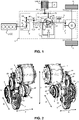
- Figure 1 shows a hybrid powertrain for a motor vehicle such as a passenger car.
- the hybrid powertrain comprises an internal combustion engine, i.e. ICE 1, with a crankshaft 11, an electric machine, i.e. EM 2, with a rotor shaft 21, two driven wheels 3 with wheel shafts 31 and with a variable transmission 4 there between.
- the known transmission 4 comprises a variator unit 9 and a first differential gearing 5.
- the variator unit 9 is provided with an input shaft 91 that is drivingly connected to, i.e. that rotates as a unit with the ICE 1 and with an output shaft 92.
- the variator unit 9 can vary a speed ratio between an input shaft 91 and an output shaft 92 thereof within a continuous range of speed ratios.
- the variator unit 9 is in the form of two rotatable, variable pulleys 93 and 94, each associated with (i.e. mounted on and is possibly partly formed integral with) a respective one of the said input and output shafts 91 and 92, and a drive belt or chain 95 that is wrapped around the pulleys 93 and 94 for drivingly connecting these.
- the first differential gearing 5 is provided with three rotatable members 51, 54, 53 that are respectively drivingly connected to, i.e. rotate as a unit with the output shaft 92 of the variator unit 9, the rotor shaft 21 of the EM 2 and the wheel shafts 31 of the driven wheels 3.
- the first differential gearing 5 balances the torque levels acting on its rotatable members 51, 54, 53, based on the rotational speed ratios provided there between.
- the first differential gearing 5 is in the form of a planetary gearing 5 provided with a central sun gear 51 that is in meshing contact with one or more planet gears 52, which planet gears 52 are rotatably carried by a planet carrier 53 arranged coaxially rotatable with the sun gear 51, and with a ring gear 54 that is in meshing contact with the planet gears 52 and that is also arranged coaxially rotatable with the sun gear 51.
- a bridging clutch 55 is provided as part of planetary gearing 5, between the planet carrier 53 and sun gear 51 thereof. This bridging clutch 55 can be closed to internally lock the planetary gearing 5 such that the sun gear 51, the planet carrier 53 and the ring gear 54 thereof rotate as a unit.
- the sun gear 51 of the planetary gearing 5 is coupled to the crankshaft 11 of the ICE 1 via a second clutch 8, an auxiliary gear 100 on an auxiliary shaft 101, an output gear 96 on the output shaft 92 meshing with that auxiliary gear 100 and the variator unit 9 itself.
- the second clutch can be selectively closed to drivingly connecting, i.e. to couple the ICE 1 and the variator unit 9 to the planetary gearing 5, or opened to decouple, i.e. to isolate the ICE 1 and the variator unit 9 from the rest of the hybrid powertrain.
- the ring gear 54 of the planetary gearing 5 is coupled to a pinion gear 22 on the rotor shaft 21 of the EM machine 2 via an idler gear 23 and the planet carrier 53 of the planetary gearing 5 is coupled to the driven wheels 3 via a final reduction gearing 7 including a further differential gearing 71.
- the final reduction gearing 7 provides a speed reduction between the ICE 1 and/or the EM 2 and the driven wheels 3, while the further differential gearing 71 thereof allows the two driven wheels 3 to each rotate at a respective rotational speed, as is common knowledge in the art.
- the transmission 4 is provided with a brake or park lock 6 that can be engaged to lock, i.e. to prevent rotation of the final reduction gearing 7, in which case the ICE 1 can drive the EM 2, in particular to charge a battery 24 of the motor vehicle, or the EM 2 can drive the ICE 1, in particular to start it, without simultaneously driving and/or rotating the driven wheels 3 of the motor vehicle.
- the park lock 6 is released, the EM 2 can drive the motor vehicle while drawing electric power from the battery 24, possibly supported by the ICE 1.
- the park lock 6 it is of course also possible to (automatically) engage the vehicle wheel brakes to charge the battery 24 without simultaneously driving the vehicle.
- the transmission 4 occupies only a relatively small installation space.
- Figure 2 provide such a preferred embodiment of the transmission 4 by the physical arrangement of the main components thereof in accordance with the present invention in two 3D views thereof and relative to a mounted position thereof in the motor vehicle.
- the transmission 4 of figure 2 incorporates the following design features in accordance with the present invention that provide for a compact physical realisation thereof:
- Figure 3 elucidates a further design aspect of the novel physical transmission arrangement of figure 2 .
- Figure 3 shows two instances of a mutual positioning of four transmission components, namely the EM 2, the variator unit input pulley 93, the variator unit output pulley and the final reduction gearing 7, and then only schematically in a side elevation of thereof.
- the input pulley 93 and the output pulley lie in the same horizontal plane HP that is defined by the said width and axial directions.
- the variator unit 9 is oriented at an angle relative to the horizontal plane HP by an axis of rotation of its output shaft 92 being located higher than that of its input shaft 91 in the vertical direction V, which latter mutual positioning corresponds to that of the figure 2 . From figure 3 , it appears that such angled orientation of the variator unit 9 significantly reduces the installation space required for the said transmission components in the vertical direction V, albeit at the expense of the somewhat increased installation space in the width direction W.
- the EM 2 can also be located lower in the vertical direction.
- the speed ratio range of the variator unit 9 can be comparatively limited, since the total speed ratio range of the transmission 4 is extended by the planetary gearing 5.
- a so-called ratio coverage (defined as the largest achievable speed ratio divided by the smallest achievable speed ratio) of the variator unit 9 needs to be between 3.0 and 4.5 only, compared to around 7.0 in a more conventional transmission arrangement without the planetary gearing 5. This latter aspect too helps to reduce the required installation space and, in particular, enables to take full advantage of the angled orientation of the variator unit 9 in this respect.
- the final reduction gearing 7 can also be located higher in the vertical direction.
- a diagonal distance between the axis of rotation of the input shaft 91 of the variator unit 9, which corresponds to the axis of rotation of the crank shaft 11 of the ICE 1, and that of the final reduction gearing 7 is remarkably reduced.
- Such reduction is considered highly advantageous, since especially this diagonal distance typically determines -and set a minimum for- the installation space required for the so-called engine bay of the motor vehicle.
- the final reduction gearing 7 can -and, in the transmission arrangement of figure 2 , does- partially overlap with the output pulley 94 in the vertical direction.
- a corresponding vertical overlap with the input pulley 93 is, however, not possible due to its considerable size in the axial direction.
- the axis of rotation of the EM 2 i.e. of its rotor shaft 21, is located close to, but still on the same side of the axis of the input pulley 93, i.e. the input shaft 91, at the axis of the output pulley 94, i.e. the output shaft 92.
- Figure 4 illustrates yet a further design aspect of the novel physical transmission arrangement of figure 2 in a schematically drawn, physical arrangement thereof.
- the auxiliary gear 100 is provided with a central opening, with the auxiliary shaft 101 extending through such opening, and with the said second clutch 8 embodied as a friction clutch and arranged between the auxiliary shaft 101 and the auxiliary gear 100 on the axial side thereof that faces away from the planetary gearing 5; 51-54.
- the said second clutch 8 interferes neither with the variator output shaft 92, nor with the auxiliary shaft 101. Therefore, the said second clutch 8 can favourably be provided with a relatively large diameter.
- the said second clutch 8 can be integrated in radial direction between the auxiliary shaft 101 and the auxiliary gear 100, which is feasible if the said second clutch 8 is embodied as a dry-friction, cone clutch. Indeed, the required slip-torque capacity of this clutch 8 is relatively low, because it does not serve as a starting clutch for the initial acceleration of the motor vehicle from standstill, but merely serves to start the ICE 1 when the operation of the transmission switches from a purely electric drive mode to a hybrid, i.e. ICE assisted drive mode.
- the bridging clutch 55 is embodied as an interference clutch (also known as a dog clutch) that is favourably simple in construction and control as compared to a friction clutch.
- an interference clutch also known as a dog clutch
- the torque and speed of the components 51-54 of the planetary gearing 5 is equalised (by the appropriate control of the ICE 1, the EM 2 and the variator unit 9.
- the carrier 53 of the planetary gearing 5; 51-54 is incorporated in the transmission 4 on the axial side of the planet gears 52 facing away from the ICE 1 and as a hollow gear provided with a central opening, with the auxiliary shaft 101 extending through it.
- the final reduction gearing 7 that is drivingly connected to the carrier 53 is optimally positioned in axial direction relative to the driven wheels 3.
- Figure 5 illustrates an alternative arrangement of the novel transmission.
- the said second clutch 8 is arranged on the auxiliary shaft 101 between the bridging clutch 55 and the planetary gearing 5; 51-54 that are arranged on the respective ends of that auxiliary shaft 101.
- a connecting shaft 102 is provided between the bridging clutch 55 and the planetary gearing 5; 51-54.
- the connecting shaft 102 is provided coaxially with the auxiliary shaft 101, whereto the latter is embodied as a hollow shaft with a central opening, with the connection shaft 102 extending through it.
- bridging clutch 55 and the planetary gearing 5; 51-54 are provided on either end of the auxiliary shaft 101 and the connecting shaft 102, such that any (torque) shocks resulting from a closing or opening of the bridging clutch 55 are dampened by a twisting of these shafts 101, 102.
- dampening effect can be enhanced by providing the connecting shaft 102 as a hollow shaft over at least a substantial part of its length.
- the connecting shaft 102 is provided as a hollow shaft over a predominant part of its length, as illustrated in figure 6 .
- the alternative arrangement of the transmission 4 of figure 5 is particularly suitable if the said second clutch 8 has a relatively small diameter, such as when it is integrated in radial direction between the auxiliary shaft 101 and the auxiliary gear 100 as mentioned hereinabove. In this case a favourably compact build of the transmission 4 can be achieved, both in the axial direction and in the height/radial direction.
- the first differential gearing 5 of the transmission 4 is embodied as a planetary gearing 5 whereof the sun gear 51 is driven by the ICE 1 and the ring gear 54 is driven by (or drives) the EM 2.
- This specific embodiment of the first differential gearing 5 is particularly suited for a powerful EM 2 with a high (maximum) torque generating capability, in particular exceeding the maximum torque of the ICE 1, e.g. by more than 25%.
- the maximum EM torque is comparable to, or less than the maximum ICE torque
- the EM 2 is still located above the input and output shafts 91, 92 of the variator unit 9 as seen in the vertical direction and the pinion gear 22 on the rotor shaft 21 of the EM 2 is still located on the same axial side of the variator unit 9 as the ICE 1.
- the carrier 53 of the planetary gearing 5 is incorporated in the transmission 4 on the axial side of the planet gears 52 facing towards the ICE 1 and is embodied as a hollow gear provided with a central opening, with a shaft of the sun gear 51 extending through it.
- the final reduction gearing 7 that is drivingly connected to the carrier 53 is optimally positioned in axial direction relative to the driven wheels 3 in this latter transmission embodiment as well.
Landscapes
- Engineering & Computer Science (AREA)
- Chemical & Material Sciences (AREA)
- Combustion & Propulsion (AREA)
- Transportation (AREA)
- Mechanical Engineering (AREA)
- Transmission Devices (AREA)
- Hybrid Electric Vehicles (AREA)
- Transmissions By Endless Flexible Members (AREA)
- Structure Of Transmissions (AREA)
Applications Claiming Priority (3)
| Application Number | Priority Date | Filing Date | Title |
|---|---|---|---|
| NL1042909 | 2018-06-22 | ||
| EP19020107 | 2019-03-06 | ||
| PCT/EP2019/025194 WO2019242893A1 (en) | 2018-06-22 | 2019-06-21 | Variable transmission for a hybrid powertrain and hybrid powertrain |
Publications (2)
| Publication Number | Publication Date |
|---|---|
| EP3810451A1 EP3810451A1 (en) | 2021-04-28 |
| EP3810451B1 true EP3810451B1 (en) | 2022-09-21 |
Family
ID=67184960
Family Applications (1)
| Application Number | Title | Priority Date | Filing Date |
|---|---|---|---|
| EP19736585.1A Active EP3810451B1 (en) | 2018-06-22 | 2019-06-21 | Hybrid powertrain with a variable transmission |
Country Status (4)
| Country | Link |
|---|---|
| EP (1) | EP3810451B1 (https=) |
| JP (1) | JP2021528311A (https=) |
| CN (1) | CN112368168A (https=) |
| WO (1) | WO2019242893A1 (https=) |
Cited By (1)
| Publication number | Priority date | Publication date | Assignee | Title |
|---|---|---|---|---|
| WO2025119898A1 (de) * | 2023-12-05 | 2025-06-12 | Rheinisch-Westfälische Technische Hochschule Aachen, abgekürzt RWTH Aachen, Körperschaft des öffentlichen Rechts | Antriebsstrang für ein kraftfahrzeug |
Family Cites Families (16)
| Publication number | Priority date | Publication date | Assignee | Title |
|---|---|---|---|---|
| JP3354074B2 (ja) | 1997-04-25 | 2002-12-09 | ジヤトコ株式会社 | パラレルハイブリッド車両の制御装置 |
| JPH11180173A (ja) * | 1997-12-19 | 1999-07-06 | Mitsubishi Motors Corp | ハイブリッド電気自動車用駆動装置 |
| DE19810374B4 (de) | 1998-03-10 | 2013-05-02 | Bayerische Motoren Werke Aktiengesellschaft | Hybridantrieb für ein Kraftfahrzeug |
| JP3817982B2 (ja) * | 1999-08-06 | 2006-09-06 | トヨタ自動車株式会社 | ハイブリッド車 |
| JP3887361B2 (ja) * | 2003-08-18 | 2007-02-28 | 本田技研工業株式会社 | ハイブリッド車両 |
| CN2848617Y (zh) * | 2005-11-18 | 2006-12-20 | 比亚迪股份有限公司 | 一种改进的动力传动系统 |
| KR100726733B1 (ko) * | 2006-02-06 | 2007-06-11 | 현대자동차주식회사 | 하이브리드 자동차의 파워 스프릿 구조 |
| KR100774665B1 (ko) * | 2006-09-21 | 2007-11-08 | 현대자동차주식회사 | 토로이달을 이용한 하이브리드 파워트레인 구조 |
| JP4900693B2 (ja) * | 2006-11-27 | 2012-03-21 | アイシン・エィ・ダブリュ株式会社 | ハイブリッド駆動装置 |
| JP2009001126A (ja) * | 2007-06-20 | 2009-01-08 | Toyota Motor Corp | ハイブリッド駆動装置 |
| CN102225684A (zh) * | 2011-05-03 | 2011-10-26 | 重庆大学 | 混合动力汽车动力传动系统 |
| JP2013032119A (ja) * | 2011-08-02 | 2013-02-14 | Honda Motor Co Ltd | ハイブリッド駆動装置 |
| JP5712156B2 (ja) * | 2012-03-28 | 2015-05-07 | ジヤトコ株式会社 | トランスミッションケース用鋳型構造及びトランスミッションケース |
| CN103009994B (zh) * | 2012-11-27 | 2017-09-19 | 奇瑞控股有限公司 | 一种混合动力汽车动力耦合装置及变速系统 |
| ITPD20130292A1 (it) * | 2013-10-23 | 2015-04-24 | Antonio Francisco Cesaroni | Gruppo di trazione per veicoli ibridi |
| NL1042199B1 (en) | 2016-12-27 | 2018-07-03 | Bosch Gmbh Robert | Method for operating a hybrid drive line with an electric motor/ generator device, an internal combustion engine and a gearing |
-
2019
- 2019-06-21 EP EP19736585.1A patent/EP3810451B1/en active Active
- 2019-06-21 WO PCT/EP2019/025194 patent/WO2019242893A1/en not_active Ceased
- 2019-06-21 JP JP2020571496A patent/JP2021528311A/ja not_active Withdrawn
- 2019-06-21 CN CN201980041937.4A patent/CN112368168A/zh active Pending
Cited By (1)
| Publication number | Priority date | Publication date | Assignee | Title |
|---|---|---|---|---|
| WO2025119898A1 (de) * | 2023-12-05 | 2025-06-12 | Rheinisch-Westfälische Technische Hochschule Aachen, abgekürzt RWTH Aachen, Körperschaft des öffentlichen Rechts | Antriebsstrang für ein kraftfahrzeug |
Also Published As
| Publication number | Publication date |
|---|---|
| CN112368168A (zh) | 2021-02-12 |
| JP2021528311A (ja) | 2021-10-21 |
| EP3810451A1 (en) | 2021-04-28 |
| WO2019242893A1 (en) | 2019-12-26 |
Similar Documents
| Publication | Publication Date | Title |
|---|---|---|
| US7174979B2 (en) | Hybrid vehicle | |
| JP3580257B2 (ja) | ハイブリッド車 | |
| US8870697B2 (en) | Power transmission device | |
| CN101191536B (zh) | 提供纯电动固定传动比的输入制动器 | |
| US11524567B2 (en) | Hybrid transmission unit having two planetary wheel sets and a plurality of switching devices; and motor vehicle | |
| JP5670562B2 (ja) | ハイブリッド推進システム | |
| US7261660B2 (en) | Electrically variable transmission arrangement with transfer gear between gear sets and clutches | |
| US7238132B2 (en) | Electrically variable transmission arrangement with transfer gear between motor/generators | |
| US7220200B2 (en) | Electrically variable transmission arrangement with spaced-apart simple planetary gear sets | |
| CN101963213B (zh) | 具有多轴传送的多速变速器 | |
| CN209008377U (zh) | 混合动力驱动系统 | |
| US11761521B2 (en) | Gear unit and powertrain for a vehicle | |
| US11752849B2 (en) | Gear unit and powertrain for a vehicle | |
| CN110001376A (zh) | 实现多动力源耦合的车用混合动力系统 | |
| JP2011230650A (ja) | ハイブリッド車両用駆動装置 | |
| US11807102B2 (en) | Gear unit and powertrain for a vehicle | |
| US20230037299A1 (en) | Gear unit and drive train for a vehicle | |
| KR101428078B1 (ko) | 차량의 하이브리드 구동장치 | |
| EP3810451B1 (en) | Hybrid powertrain with a variable transmission | |
| JPH09226393A (ja) | ハイブリッド駆動装置 | |
| US11738633B2 (en) | Gear unit and powertrain for a vehicle | |
| CN208428949U (zh) | 混合动力驱动系统 | |
| CN113580919B (zh) | 混合动力装置及具有其的车辆 | |
| CN213501829U (zh) | 一种混合动力变速器、动力总成及车辆 | |
| CN110289730B (zh) | 一种仿生机器人混合动力可变功率动力单元及其传递方法 |
Legal Events
| Date | Code | Title | Description |
|---|---|---|---|
| STAA | Information on the status of an ep patent application or granted ep patent |
Free format text: STATUS: UNKNOWN |
|
| STAA | Information on the status of an ep patent application or granted ep patent |
Free format text: STATUS: THE INTERNATIONAL PUBLICATION HAS BEEN MADE |
|
| PUAI | Public reference made under article 153(3) epc to a published international application that has entered the european phase |
Free format text: ORIGINAL CODE: 0009012 |
|
| STAA | Information on the status of an ep patent application or granted ep patent |
Free format text: STATUS: REQUEST FOR EXAMINATION WAS MADE |
|
| 17P | Request for examination filed |
Effective date: 20201219 |
|
| AK | Designated contracting states |
Kind code of ref document: A1 Designated state(s): AL AT BE BG CH CY CZ DE DK EE ES FI FR GB GR HR HU IE IS IT LI LT LU LV MC MK MT NL NO PL PT RO RS SE SI SK SM TR |
|
| AX | Request for extension of the european patent |
Extension state: BA ME |
|
| DAV | Request for validation of the european patent (deleted) | ||
| DAX | Request for extension of the european patent (deleted) | ||
| GRAP | Despatch of communication of intention to grant a patent |
Free format text: ORIGINAL CODE: EPIDOSNIGR1 |
|
| STAA | Information on the status of an ep patent application or granted ep patent |
Free format text: STATUS: GRANT OF PATENT IS INTENDED |
|
| INTG | Intention to grant announced |
Effective date: 20220511 |
|
| GRAS | Grant fee paid |
Free format text: ORIGINAL CODE: EPIDOSNIGR3 |
|
| GRAA | (expected) grant |
Free format text: ORIGINAL CODE: 0009210 |
|
| STAA | Information on the status of an ep patent application or granted ep patent |
Free format text: STATUS: THE PATENT HAS BEEN GRANTED |
|
| AK | Designated contracting states |
Kind code of ref document: B1 Designated state(s): AL AT BE BG CH CY CZ DE DK EE ES FI FR GB GR HR HU IE IS IT LI LT LU LV MC MK MT NL NO PL PT RO RS SE SI SK SM TR |
|
| REG | Reference to a national code |
Ref country code: GB Ref legal event code: FG4D |
|
| REG | Reference to a national code |
Ref country code: CH Ref legal event code: EP |
|
| REG | Reference to a national code |
Ref country code: IE Ref legal event code: FG4D |
|
| REG | Reference to a national code |
Ref country code: DE Ref legal event code: R096 Ref document number: 602019019812 Country of ref document: DE |
|
| REG | Reference to a national code |
Ref country code: AT Ref legal event code: REF Ref document number: 1519788 Country of ref document: AT Kind code of ref document: T Effective date: 20221015 |
|
| REG | Reference to a national code |
Ref country code: LT Ref legal event code: MG9D |
|
| REG | Reference to a national code |
Ref country code: NL Ref legal event code: MP Effective date: 20220921 |
|
| PG25 | Lapsed in a contracting state [announced via postgrant information from national office to epo] |
Ref country code: SE Free format text: LAPSE BECAUSE OF FAILURE TO SUBMIT A TRANSLATION OF THE DESCRIPTION OR TO PAY THE FEE WITHIN THE PRESCRIBED TIME-LIMIT Effective date: 20220921 Ref country code: RS Free format text: LAPSE BECAUSE OF FAILURE TO SUBMIT A TRANSLATION OF THE DESCRIPTION OR TO PAY THE FEE WITHIN THE PRESCRIBED TIME-LIMIT Effective date: 20220921 Ref country code: NO Free format text: LAPSE BECAUSE OF FAILURE TO SUBMIT A TRANSLATION OF THE DESCRIPTION OR TO PAY THE FEE WITHIN THE PRESCRIBED TIME-LIMIT Effective date: 20221221 Ref country code: LV Free format text: LAPSE BECAUSE OF FAILURE TO SUBMIT A TRANSLATION OF THE DESCRIPTION OR TO PAY THE FEE WITHIN THE PRESCRIBED TIME-LIMIT Effective date: 20220921 Ref country code: LT Free format text: LAPSE BECAUSE OF FAILURE TO SUBMIT A TRANSLATION OF THE DESCRIPTION OR TO PAY THE FEE WITHIN THE PRESCRIBED TIME-LIMIT Effective date: 20220921 Ref country code: FI Free format text: LAPSE BECAUSE OF FAILURE TO SUBMIT A TRANSLATION OF THE DESCRIPTION OR TO PAY THE FEE WITHIN THE PRESCRIBED TIME-LIMIT Effective date: 20220921 |
|
| REG | Reference to a national code |
Ref country code: AT Ref legal event code: MK05 Ref document number: 1519788 Country of ref document: AT Kind code of ref document: T Effective date: 20220921 |
|
| PG25 | Lapsed in a contracting state [announced via postgrant information from national office to epo] |
Ref country code: HR Free format text: LAPSE BECAUSE OF FAILURE TO SUBMIT A TRANSLATION OF THE DESCRIPTION OR TO PAY THE FEE WITHIN THE PRESCRIBED TIME-LIMIT Effective date: 20220921 Ref country code: GR Free format text: LAPSE BECAUSE OF FAILURE TO SUBMIT A TRANSLATION OF THE DESCRIPTION OR TO PAY THE FEE WITHIN THE PRESCRIBED TIME-LIMIT Effective date: 20221222 |
|
| PG25 | Lapsed in a contracting state [announced via postgrant information from national office to epo] |
Ref country code: SM Free format text: LAPSE BECAUSE OF FAILURE TO SUBMIT A TRANSLATION OF THE DESCRIPTION OR TO PAY THE FEE WITHIN THE PRESCRIBED TIME-LIMIT Effective date: 20220921 Ref country code: RO Free format text: LAPSE BECAUSE OF FAILURE TO SUBMIT A TRANSLATION OF THE DESCRIPTION OR TO PAY THE FEE WITHIN THE PRESCRIBED TIME-LIMIT Effective date: 20220921 Ref country code: PT Free format text: LAPSE BECAUSE OF FAILURE TO SUBMIT A TRANSLATION OF THE DESCRIPTION OR TO PAY THE FEE WITHIN THE PRESCRIBED TIME-LIMIT Effective date: 20230123 Ref country code: ES Free format text: LAPSE BECAUSE OF FAILURE TO SUBMIT A TRANSLATION OF THE DESCRIPTION OR TO PAY THE FEE WITHIN THE PRESCRIBED TIME-LIMIT Effective date: 20220921 Ref country code: CZ Free format text: LAPSE BECAUSE OF FAILURE TO SUBMIT A TRANSLATION OF THE DESCRIPTION OR TO PAY THE FEE WITHIN THE PRESCRIBED TIME-LIMIT Effective date: 20220921 Ref country code: AT Free format text: LAPSE BECAUSE OF FAILURE TO SUBMIT A TRANSLATION OF THE DESCRIPTION OR TO PAY THE FEE WITHIN THE PRESCRIBED TIME-LIMIT Effective date: 20220921 |
|
| PG25 | Lapsed in a contracting state [announced via postgrant information from national office to epo] |
Ref country code: SK Free format text: LAPSE BECAUSE OF FAILURE TO SUBMIT A TRANSLATION OF THE DESCRIPTION OR TO PAY THE FEE WITHIN THE PRESCRIBED TIME-LIMIT Effective date: 20220921 Ref country code: PL Free format text: LAPSE BECAUSE OF FAILURE TO SUBMIT A TRANSLATION OF THE DESCRIPTION OR TO PAY THE FEE WITHIN THE PRESCRIBED TIME-LIMIT Effective date: 20220921 Ref country code: IS Free format text: LAPSE BECAUSE OF FAILURE TO SUBMIT A TRANSLATION OF THE DESCRIPTION OR TO PAY THE FEE WITHIN THE PRESCRIBED TIME-LIMIT Effective date: 20230121 Ref country code: EE Free format text: LAPSE BECAUSE OF FAILURE TO SUBMIT A TRANSLATION OF THE DESCRIPTION OR TO PAY THE FEE WITHIN THE PRESCRIBED TIME-LIMIT Effective date: 20220921 |
|
| REG | Reference to a national code |
Ref country code: DE Ref legal event code: R097 Ref document number: 602019019812 Country of ref document: DE |
|
| PG25 | Lapsed in a contracting state [announced via postgrant information from national office to epo] |
Ref country code: NL Free format text: LAPSE BECAUSE OF FAILURE TO SUBMIT A TRANSLATION OF THE DESCRIPTION OR TO PAY THE FEE WITHIN THE PRESCRIBED TIME-LIMIT Effective date: 20220921 Ref country code: AL Free format text: LAPSE BECAUSE OF FAILURE TO SUBMIT A TRANSLATION OF THE DESCRIPTION OR TO PAY THE FEE WITHIN THE PRESCRIBED TIME-LIMIT Effective date: 20220921 |
|
| PLBE | No opposition filed within time limit |
Free format text: ORIGINAL CODE: 0009261 |
|
| STAA | Information on the status of an ep patent application or granted ep patent |
Free format text: STATUS: NO OPPOSITION FILED WITHIN TIME LIMIT |
|
| PG25 | Lapsed in a contracting state [announced via postgrant information from national office to epo] |
Ref country code: DK Free format text: LAPSE BECAUSE OF FAILURE TO SUBMIT A TRANSLATION OF THE DESCRIPTION OR TO PAY THE FEE WITHIN THE PRESCRIBED TIME-LIMIT Effective date: 20220921 |
|
| 26N | No opposition filed |
Effective date: 20230622 |
|
| PG25 | Lapsed in a contracting state [announced via postgrant information from national office to epo] |
Ref country code: SI Free format text: LAPSE BECAUSE OF FAILURE TO SUBMIT A TRANSLATION OF THE DESCRIPTION OR TO PAY THE FEE WITHIN THE PRESCRIBED TIME-LIMIT Effective date: 20220921 |
|
| REG | Reference to a national code |
Ref country code: DE Ref legal event code: R119 Ref document number: 602019019812 Country of ref document: DE |
|
| PG25 | Lapsed in a contracting state [announced via postgrant information from national office to epo] |
Ref country code: MC Free format text: LAPSE BECAUSE OF FAILURE TO SUBMIT A TRANSLATION OF THE DESCRIPTION OR TO PAY THE FEE WITHIN THE PRESCRIBED TIME-LIMIT Effective date: 20220921 |
|
| PG25 | Lapsed in a contracting state [announced via postgrant information from national office to epo] |
Ref country code: MC Free format text: LAPSE BECAUSE OF FAILURE TO SUBMIT A TRANSLATION OF THE DESCRIPTION OR TO PAY THE FEE WITHIN THE PRESCRIBED TIME-LIMIT Effective date: 20220921 |
|
| REG | Reference to a national code |
Ref country code: CH Ref legal event code: PL |
|
| REG | Reference to a national code |
Ref country code: BE Ref legal event code: MM Effective date: 20230630 |
|
| GBPC | Gb: european patent ceased through non-payment of renewal fee |
Effective date: 20230621 |
|
| PG25 | Lapsed in a contracting state [announced via postgrant information from national office to epo] |
Ref country code: LU Free format text: LAPSE BECAUSE OF NON-PAYMENT OF DUE FEES Effective date: 20230621 |
|
| REG | Reference to a national code |
Ref country code: IE Ref legal event code: MM4A |
|
| PG25 | Lapsed in a contracting state [announced via postgrant information from national office to epo] |
Ref country code: LU Free format text: LAPSE BECAUSE OF NON-PAYMENT OF DUE FEES Effective date: 20230621 |
|
| PG25 | Lapsed in a contracting state [announced via postgrant information from national office to epo] |
Ref country code: IE Free format text: LAPSE BECAUSE OF NON-PAYMENT OF DUE FEES Effective date: 20230621 |
|
| PG25 | Lapsed in a contracting state [announced via postgrant information from national office to epo] |
Ref country code: IE Free format text: LAPSE BECAUSE OF NON-PAYMENT OF DUE FEES Effective date: 20230621 Ref country code: DE Free format text: LAPSE BECAUSE OF NON-PAYMENT OF DUE FEES Effective date: 20240103 Ref country code: CH Free format text: LAPSE BECAUSE OF NON-PAYMENT OF DUE FEES Effective date: 20230630 Ref country code: GB Free format text: LAPSE BECAUSE OF NON-PAYMENT OF DUE FEES Effective date: 20230621 |
|
| PG25 | Lapsed in a contracting state [announced via postgrant information from national office to epo] |
Ref country code: IT Free format text: LAPSE BECAUSE OF FAILURE TO SUBMIT A TRANSLATION OF THE DESCRIPTION OR TO PAY THE FEE WITHIN THE PRESCRIBED TIME-LIMIT Effective date: 20220921 Ref country code: FR Free format text: LAPSE BECAUSE OF NON-PAYMENT OF DUE FEES Effective date: 20230630 Ref country code: BE Free format text: LAPSE BECAUSE OF NON-PAYMENT OF DUE FEES Effective date: 20230630 |
|
| PG25 | Lapsed in a contracting state [announced via postgrant information from national office to epo] |
Ref country code: BG Free format text: LAPSE BECAUSE OF FAILURE TO SUBMIT A TRANSLATION OF THE DESCRIPTION OR TO PAY THE FEE WITHIN THE PRESCRIBED TIME-LIMIT Effective date: 20220921 |
|
| PG25 | Lapsed in a contracting state [announced via postgrant information from national office to epo] |
Ref country code: BG Free format text: LAPSE BECAUSE OF FAILURE TO SUBMIT A TRANSLATION OF THE DESCRIPTION OR TO PAY THE FEE WITHIN THE PRESCRIBED TIME-LIMIT Effective date: 20220921 |
|
| PG25 | Lapsed in a contracting state [announced via postgrant information from national office to epo] |
Ref country code: CY Free format text: LAPSE BECAUSE OF FAILURE TO SUBMIT A TRANSLATION OF THE DESCRIPTION OR TO PAY THE FEE WITHIN THE PRESCRIBED TIME-LIMIT; INVALID AB INITIO Effective date: 20190621 |
|
| PG25 | Lapsed in a contracting state [announced via postgrant information from national office to epo] |
Ref country code: HU Free format text: LAPSE BECAUSE OF FAILURE TO SUBMIT A TRANSLATION OF THE DESCRIPTION OR TO PAY THE FEE WITHIN THE PRESCRIBED TIME-LIMIT; INVALID AB INITIO Effective date: 20190621 |
|
| PG25 | Lapsed in a contracting state [announced via postgrant information from national office to epo] |
Ref country code: TR Free format text: LAPSE BECAUSE OF FAILURE TO SUBMIT A TRANSLATION OF THE DESCRIPTION OR TO PAY THE FEE WITHIN THE PRESCRIBED TIME-LIMIT Effective date: 20220921 |