EP3809502A1 - Positivelektrodenstromkollektor, positivelektrodenplatte, elektrochemische vorrichtung und elektrische einrichtung mit elektrochemischer vorrichtung - Google Patents
Positivelektrodenstromkollektor, positivelektrodenplatte, elektrochemische vorrichtung und elektrische einrichtung mit elektrochemischer vorrichtung Download PDFInfo
- Publication number
- EP3809502A1 EP3809502A1 EP20814019.4A EP20814019A EP3809502A1 EP 3809502 A1 EP3809502 A1 EP 3809502A1 EP 20814019 A EP20814019 A EP 20814019A EP 3809502 A1 EP3809502 A1 EP 3809502A1
- Authority
- EP
- European Patent Office
- Prior art keywords
- positive electrode
- blocking activation
- overcharge blocking
- current collector
- layer
- Prior art date
- Legal status (The legal status is an assumption and is not a legal conclusion. Google has not performed a legal analysis and makes no representation as to the accuracy of the status listed.)
- Granted
Links
Images

Classifications
-
- H—ELECTRICITY
- H01—ELECTRIC ELEMENTS
- H01M—PROCESSES OR MEANS, e.g. BATTERIES, FOR THE DIRECT CONVERSION OF CHEMICAL ENERGY INTO ELECTRICAL ENERGY
- H01M4/00—Electrodes
- H01M4/02—Electrodes composed of, or comprising, active material
- H01M4/64—Carriers or collectors
- H01M4/66—Selection of materials
- H01M4/665—Composites
- H01M4/667—Composites in the form of layers, e.g. coatings
-
- H—ELECTRICITY
- H01—ELECTRIC ELEMENTS
- H01M—PROCESSES OR MEANS, e.g. BATTERIES, FOR THE DIRECT CONVERSION OF CHEMICAL ENERGY INTO ELECTRICAL ENERGY
- H01M10/00—Secondary cells; Manufacture thereof
- H01M10/42—Methods or arrangements for servicing or maintenance of secondary cells or secondary half-cells
- H01M10/4235—Safety or regulating additives or arrangements in electrodes, separators or electrolyte
-
- H—ELECTRICITY
- H01—ELECTRIC ELEMENTS
- H01M—PROCESSES OR MEANS, e.g. BATTERIES, FOR THE DIRECT CONVERSION OF CHEMICAL ENERGY INTO ELECTRICAL ENERGY
- H01M4/00—Electrodes
- H01M4/02—Electrodes composed of, or comprising, active material
- H01M4/13—Electrodes for accumulators with non-aqueous electrolyte, e.g. for lithium-accumulators; Processes of manufacture thereof
- H01M4/131—Electrodes based on mixed oxides or hydroxides, or on mixtures of oxides or hydroxides, e.g. LiCoOx
-
- H—ELECTRICITY
- H01—ELECTRIC ELEMENTS
- H01M—PROCESSES OR MEANS, e.g. BATTERIES, FOR THE DIRECT CONVERSION OF CHEMICAL ENERGY INTO ELECTRICAL ENERGY
- H01M4/00—Electrodes
- H01M4/02—Electrodes composed of, or comprising, active material
- H01M4/13—Electrodes for accumulators with non-aqueous electrolyte, e.g. for lithium-accumulators; Processes of manufacture thereof
- H01M4/136—Electrodes based on inorganic compounds other than oxides or hydroxides, e.g. sulfides, selenides, tellurides, halogenides or LiCoFy
-
- H—ELECTRICITY
- H01—ELECTRIC ELEMENTS
- H01M—PROCESSES OR MEANS, e.g. BATTERIES, FOR THE DIRECT CONVERSION OF CHEMICAL ENERGY INTO ELECTRICAL ENERGY
- H01M4/00—Electrodes
- H01M4/02—Electrodes composed of, or comprising, active material
- H01M4/62—Selection of inactive substances as ingredients for active masses, e.g. binders, fillers
- H01M4/621—Binders
- H01M4/622—Binders being polymers
- H01M4/623—Binders being polymers fluorinated polymers
-
- H—ELECTRICITY
- H01—ELECTRIC ELEMENTS
- H01M—PROCESSES OR MEANS, e.g. BATTERIES, FOR THE DIRECT CONVERSION OF CHEMICAL ENERGY INTO ELECTRICAL ENERGY
- H01M4/00—Electrodes
- H01M4/02—Electrodes composed of, or comprising, active material
- H01M4/64—Carriers or collectors
- H01M4/66—Selection of materials
- H01M4/661—Metal or alloys, e.g. alloy coatings
-
- H—ELECTRICITY
- H01—ELECTRIC ELEMENTS
- H01M—PROCESSES OR MEANS, e.g. BATTERIES, FOR THE DIRECT CONVERSION OF CHEMICAL ENERGY INTO ELECTRICAL ENERGY
- H01M4/00—Electrodes
- H01M4/02—Electrodes composed of, or comprising, active material
- H01M4/64—Carriers or collectors
- H01M4/66—Selection of materials
- H01M4/663—Selection of materials containing carbon or carbonaceous materials as conductive part, e.g. graphite, carbon fibres
-
- H—ELECTRICITY
- H01—ELECTRIC ELEMENTS
- H01M—PROCESSES OR MEANS, e.g. BATTERIES, FOR THE DIRECT CONVERSION OF CHEMICAL ENERGY INTO ELECTRICAL ENERGY
- H01M4/00—Electrodes
- H01M4/02—Electrodes composed of, or comprising, active material
- H01M4/64—Carriers or collectors
- H01M4/66—Selection of materials
- H01M4/668—Composites of electroconductive material and synthetic resins
-
- H—ELECTRICITY
- H01—ELECTRIC ELEMENTS
- H01M—PROCESSES OR MEANS, e.g. BATTERIES, FOR THE DIRECT CONVERSION OF CHEMICAL ENERGY INTO ELECTRICAL ENERGY
- H01M10/00—Secondary cells; Manufacture thereof
- H01M10/05—Accumulators with non-aqueous electrolyte
- H01M10/052—Li-accumulators
- H01M10/0525—Rocking-chair batteries, i.e. batteries with lithium insertion or intercalation in both electrodes; Lithium-ion batteries
Definitions
- This application belongs to the technical field of energy storage devices, and specifically relates to a positive electrode current collector, a positive electrode, an electrochemical device, and electric equipment comprising the electrochemical device.
- Electrochemical devices with lithium ion secondary batteries as representatives mainly rely on the back-and-forth migration of active ions between positive electrode active material and negative electrode active material for charging and discharging. Electrochemical devices can provide stable voltage and current during use, and are green and environmentally friendly during use, so they are widely used in various electric equipment, such as mobile phones, tablet computers, notebook computers, electric bicycles, electric cars, etc.
- a first aspect of the present application provides a positive electrode current collector including: a metal conductive layer; an overcharge blocking activation layer disposed on surface of the metal conductive layer, the overcharge blocking activation layer including an overcharge blocking activation material, a binder material and a conductive material, wherein the overcharge blocking activation material includes an esterified saccharide.
- a second aspect of the present application provides a positive electrode plate including the positive electrode current collector according to the first aspect of the present application; a positive electrode active material layer disposed on surface of the overcharge blocking activation layer facing away from the metal conductive layer.
- a third aspect of the present application provides an electrochemical device including the positive electrode plate according to the second aspect of the present application, a negative electrode plate, and a separator.
- a fourth aspect of the present application provides electric equipment including the electrochemical device according to the third aspect of the present application.
- the positive electrode current collector including a metal conductive layer and an overcharge blocking activation layer disposed on surface of the metal conductive layer, the overcharge blocking activation layer including an esterified saccharide overcharge blocking activation material, in case an electrochemical device including the positive electrode current collector is overcharged, the charging current can be cut off in time, effectively preventing the electrochemical device from thermal runaway and avoiding safety problems such as fire and explosion, and thus improving the overcharge safety performance of the electrochemical device.
- the electric equipment of the present application includes said electrochemical device, and thus has at least the same advantages as the electrochemical device.
- any lower limit may be combined with any upper limit to form a range that is not explicitly described; and any lower limit may be combined with other lower limits to form an unspecified range, and any upper limit may be combined with any other upper limit to form an unspecified range.
- each point or single value between the endpoints of the range is included in the range. Thus, each point or single value can be combined with any other point or single value or combined with other lower or upper limits to form a range that is not explicitly specified.
- Embodiments of the present application provide a positive electrode current collector that can improve overcharge safety performance of an electrochemical device.
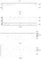
- the positive electrode current collector 10 comprises a metal conductive layer 101 and an overcharge blocking activation layer 102 disposed on surface of the metal conductive layer 101.
- the overcharge blocking activation layer 102 may be disposed on any one of two opposite surfaces of the metal conductive layer 101 in its thickness direction (see Fig. 1 ), or on both of two opposite surfaces of the metal conductive layer 101 (see Fig. 2 ).
- the overcharge blocking activation layer 102 comprises an overcharge blocking activation material, a binder material and a conductive material, wherein the overcharge blocking activation material includes an esterified saccharide.
- the overcharge blocking activation layer 102 is disposed on surface of the metal conductive layer 101, and comprises an esterified saccharide overcharge blocking activation material, a binder material and a conductive material. Under normal working environment of an electrochemical device, physical and chemical properties of the esterified saccharide overcharge blocking activation material are stable, and the conductive material forms a continuous conductive network, so that the overcharge blocking activation layer 102 has a relatively small resistance, ensuring good electrical conductivity of the positive electrode current collector 10.
- esterified saccharide overcharge blocking activation material can undergo a chemical reaction under high temperature ( ⁇ 60°C) and high voltage ( ⁇ 4.8V, relative to lithium metal potential), resulting in changes in the physical structure of the material.
- This will cause the conductive material particles in the overcharge blocking activation layer 102 to separate, lead to the broken and destroyed conductive network, so that the resistance of the overcharge blocking activation layer 102 will increase sharply.
- the charging current is cut off in time, effectively preventing the electrochemical device from thermal runaway, avoiding safety problems such as fire and explosion, and thus improving the overcharge safety performance of the electrochemical device.
- the overcharge blocking activation layer 102 achieves the purpose of disconnecting the conductive network and cutting off the charging current by the way that is different from volume expansion due to the crystallinity change of the overcharge blocking activation material at high temperature.
- the overcharge blocking activation layer 102 has relatively high reliability, because as long as the temperature and voltage of the overcharge blocking activation layer 102 reach the above-mentioned threshold (i.e. the temperature of ⁇ 60°C; the voltage of ⁇ 4.8V, relative to the lithium metal potential), the overcharge blocking activation layer 102 undergoes rapid chemical reaction, causing the broken and destroyed conductive network, so that charging current is cut off in time. In contrast, only physical changes occur under high temperature, for materials that change in crystallinity to cause volume expansion.
- the physical changes are greatly influenced by the preparation process of material coating and the preparation process of the electrochemical device.
- crystallinity of materials are influenced by the temperature and coating speed of the preparation process of material coating, the electrolyte in the electrochemical device, and the like. These influences are uncontrollable.
- the material is probably not activated, so that the charging current cannot be cut off in time, causing potential safety hazard.
- esterified saccharide has an ester group on saccharide ring (or sugar ring).
- more than one secondary hydroxyl group on saccharide ring of the saccharide is esterified.
- an esterified saccharide having an ester group on saccharide ring has high response sensitivity to high temperature ( ⁇ 60°C) and high voltage ( ⁇ 4.8V, relative to lithium metal potential), so that the overcharge blocking activation layer 102 can respond rapidly and cut off charging current, thereby better improving the overcharge safety performance of the electrochemical device.
- the esterified saccharide may be one or more of mono-esterified esterified saccharide and poly-esterified saccharide.
- Mono-esterified esterified saccharide that is, mono-esterified products of saccharide, refers to a product in which a hydrogen atom of one hydroxyl group in saccharide is replaced by an acyl group, and preferably includes a product in which a hydrogen atom of one secondary hydroxyl group on saccharide ring in saccharide is replaced by an acyl group.
- Poly-esterified saccharide that is, poly-esterified products of saccharide, refers to a product in which hydrogen atoms of two or more hydroxyl groups in saccharide are replaced by acyl groups, and preferably the product has ester group on saccharide ring.
- the esterified saccharide includes an esterification product of saccharide in which two or more hydroxyl groups are esterified and a predetermined amount of hydroxyl groups are retained.
- the residual hydroxyl groups in the esterified saccharide may promote the activation of the esterified saccharide overcharge blocking activation material under a condition of a high temperature and a high voltage and thus block overcharging current in time, thereby improving overcharging safety performance and reliability.
- the hydroxyl groups in the above mentioned predetermined amount include hydroxyl groups on saccharide ring.
- saccharide After mono-esterification or poly-esterification, saccharide forms saccharide moiety of the esterified saccharide.
- Saccharide may be one or more of monosaccharides, oligosaccharides, polysaccharides, amino sugars, sugar alcohols, deoxysugars, and uronic acids.
- saccharide is one or more of monosaccharides, oligosaccharides, and polysaccharides.
- saccharide is one or more of oligosaccharides, and polysaccharides.
- Monosaccharides include, for example, one or more of ribose, xylose, galactose, mannose, glucose, and fructose.
- Oligosaccharides comprises from 2 to 10 monosaccharide units, for example includes one or more of maltose, lactose, sucrose, cello-oligosaccharides with a degree of polymerization of 2 to 10, maltotriose, maltotetraose, maltopentaose, maltohexaose, isomaltose, isomaltotriose, panose, mannotriose, and cyclodextrin containing less than or equal to 10 monosaccharide units. Cyclodextrin containing less than or equal to 10 monosaccharide units is for example ⁇ -cyclodextrin, ⁇ -cyclodextrin, and ⁇ -cyclodextrin.
- Polysaccharides comprises more than 10 monosaccharide units, preferably more than 10 and less than or equal to 500 monosaccharide units.
- Polysaccharides includes, for example, one or more of starch, cellulose, chitosan, and cyclodextrin containing more than 10 monosaccharide units.
- Amino sugars are for example saccharides obtained by replacing part of hydroxyl groups of the above-mentioned monosaccharides, oligosaccharides, and polysaccharides with amino groups.
- the above-mentioned part of hydroxyl groups has a number of greater than or equal to 1 groups.
- Sugar alcohols are for example sorbitol, mannitol, maltitol, lactitol, xylitol, and the like.
- Deoxysugars are for example saccharides obtained by replacing part of hydroxyl groups of the above-mentioned monosaccharides, oligosaccharides, and polysaccharides with hydrogen atoms.
- the above-mentioned part of hydroxyl groups has a number of greater than or equal to 1 groups.
- Uronic acids are for example saccharides obtained by oxidizing primary hydroxyl groups of the above-mentioned monosaccharides, oligosaccharides, and polysaccharides with carboxyl groups.
- the saccharide is selected from one or more of glucose, cello-oligosaccharides, cyclodextrin, cellulose and chitosan. More preferably, the saccharide is selected from one or more of glucose, cello-oligosaccharides with a degree of polymerization of 2 to 10, cyclodextrins containing 6 to 10 monosaccharide units, celluloses with a degree of polymerization of 10 to 500, and chitosans with a degree of polymerization of 10 to 500.
- the acyl group preferably includes one or more of acyl groups represented by Formula 1 to Formula 6: wherein R 1 , R 2 , R 3 , R 4 , R 5 , R 6 , and R 7 are independently hydrogen atom, unsaturated aliphatic group, saturated aliphatic group or aromatic group, R 8 is -(CH 2 ) n -, and 0 ⁇ n ⁇ 8.
- Unsaturated aliphatic group comprises chain unsaturated aliphatic group, cyclic aliphatic groups, such as chain or cyclic alkenyl groups with 2 to 12 carbon atoms, chain or cyclic alkynyl groups with 2 to 12 carbon atoms.
- unsaturated aliphatic group is selected from one or more of ethenyl, 1-propenyl, 2-methylpropenyl, 1-butenyl, 2-butenyl, 3-butenyl, 1-propynyl, 2-propynyl, cyclobutenyl, cyclopentenyl, cyclohexenyl.
- Saturated aliphatic group comprises chain saturated aliphatic group, cyclic saturated aliphatic group.
- the chain saturated aliphatic group is for example straight or branched chain alkyl group with 1 to 12 carbon atoms, such as selected from one or more of methyl, ethyl, propyl, isopropyl, butyl, isobutyl, pentyl, isopentyl, hexyl and the isomers thereof.
- the cyclic saturated aliphatic group is for example a cyclic alkyl group having 3 to 15 carbon atoms, with or without a side chain, such as selected from one or more of cyclopropyl, cyclobutyl, cyclopentyl, cyclohexyl.
- Aromatic group is for example selected from one or more of 1-benzyl, 1-phenethyl and the like.
- n is for example 1, 2, 3, 4, 5, or 6.
- the acyl group is selected from one or more of Formula 1, Formula 2 and Formula 5.
- the acyl group is more preferably Formula 2, that is, carbonate esterified saccharides are preferred.
- R 1 is selected from one or more of methyl, ethyl, propyl, and isopropyl
- R 2 , R 5 , and R 6 are each independently a hydrogen atom, methyl, ethyl, propyl, or isopropyl.
- the esterified saccharide having these acyl groups have better reactivity under high temperature ( ⁇ 60°C) and high voltage ( ⁇ 4.8V, relative to lithium metal potential), and higher response sensitivity when electrochemical device is overcharged, so that the overcharge blocking activation layer 102 responds rapidly and cuts off charging current, thereby further improving the overcharge safety performance of the electrochemical device.
- Donor of the acyl group may be the corresponding carboxylic acids, oxygen-containing inorganic acids, acid halides, acid anhydrides, carbonates, sulfonates or phosphates.
- Acid halide is, for example, an acid chloride.
- the overcharge blocking activation material may comprise one or more of polyesterification products of monosaccharides, polyesterification products of oligosaccharides and polyesterification products of polysaccharides. Further, the overcharge blocking activation material may include one or more of polyesterified products of oligosaccharides and polyesterified products of polysaccharides. Yet further, the polyesterification products are preferably carbonates. Furthermore, the polyesterification product contains a predetermined amount of hydroxyl groups on saccharide ring.
- the overcharge blocking activation material may be selected from one or more of glucose pentaacetate, ethyl ester of glucose-1,6-diphosphate (for example, glucose-1,6-di(ethyl phosphate)), methyl ester of glucose-1,6-dicarbonate (for examples, glucose-1,6-di(methyl carbonate)), ⁇ -cyclodextrin acetate, ⁇ -cyclodextrin carbonate, ⁇ -cyclodextrin phosphate, cellulose methyl carbonate, cellulose ethyl carbonate, cellulose methyl phosphate, cellulose ethyl phosphate, chitosan methyl carbonate, chitosan ethyl carbonate, chitosan methyl phosphate, and chitosan ethyl phosphate.
- glucose pentaacetate ethyl ester of glucose-1,6-diphosphate
- the binder material in the overcharge blocking activation layer 102 may be a binder material with good high temperature resistance.
- the binder material preferably comprises one or more of polyvinylidene fluoride (PVDF), vinylidene fluoride-hexafluoropropylene copolymer (PVDF-HFP), polyurethane, polyacrylonitrile (PAN), polyimide (PI), epoxy resin, organic silicone resin, ethylene-vinyl acetate copolymer (EVA), styrene-butadiene rubber (SBR), styrene-acrylic rubber, polyacrylic acid (PAA), acrylic acid-acrylate copolymer, and ethylene-acrylate copolymer (EMA).
- the binder material has relatively high thermal stability, which is beneficial to improve the stability of the overcharge blocking activation layer 102 during the normal operation of electrochemical device; and it can ensure high binding force between the overcharge blocking activation layer 102 and the metal conductive layer 101.
- the conductive material in the overcharge blocking activation layer 102 may comprise one or more of metal conductive materials, carbon-based conductive materials, and conductive polymer materials.
- Metal conductive materials comprise, for example, one or more of aluminum, aluminum alloy, copper, copper alloy, nickel, nickel alloy, titanium, and silver.
- Carbon-based conductive materials comprise, for example, one or more of Ketjen black, mesophase carbon microspheres, activated carbon, graphite, conductive carbon black, acetylene black, carbon fiber, carbon nanotube, and graphene.
- Conductive polymer materials comprise, for example, one or more of polysulfur nitrides, aliphatic conjugated polymers, aromatic ring conjugated polymers, and aromatic heterocyclic conjugated polymers.
- the aliphatic conjugated polymer is, for example, polyacetylene.
- the aromatic ring conjugated polymer is, for example, one or more of polyphenylene, polynaphthalene.
- the aromatic heterocyclic conjugated polymer is, for example, one or more of polypyrrole, polyacetylene, polyaniline, polythiophene, and polypyridine. Conductivity of the conductive polymer material may also be improved by doping modification.
- mass percentage of the overcharge blocking activation material is from 25% to 45%, mass percentage of the binder material is from 35% to 60%, and mass percentage of the conductive material is from 6% to 20%.
- Such overcharge blocking activation layer 102 has a low resistance and can effectively improve the overcharge safety performance of the electrochemical device.
- mass percentage of the overcharge blocking activation material is from 30% to 40%, mass percentage of the binder material is from 45% to 55%, and mass percentage of the conductive material is from 6% to 10%.
- the overcharge blocking activation layer 102 may also comprise auxiliary materials.
- the auxiliary materials are materials that have good affinity with the overcharge blocking activation material, the binder material, and the conductive material.
- the auxiliary materials may improve the compatibility and affinity of the overcharge blocking activation material, the binder material and the conductive material with each other, thereby improving the uniformity of dispersion of the overcharge blocking activation material and the conductive material in the binder material, and the flatness of the overcharge blocking activation layer 102, and reducing the defects such as pits in the layer. This may improve the overall protection of the overcharge blocking activation layer 102.
- the overcharge blocking activation material When electrochemical device is overcharged, the overcharge blocking activation material will respond at any point of the positive electrode current collector 10, preventing potential safety hazard caused by leakage of electricity between the positive electrode active material layer 20 (see Fig. 3 to Fig. 5 ) and the metal conductive layer 101.
- the overcharge blocking activation material and the conductive material are uniformly dispersed in the binder material, so that the conductive material forms a uniform and continuous conductive network, ensuring relatively low resistance of the overcharge blocking activation layer 102 during normal charging and discharging and relatively good performance (such as cycle performance) of the electrochemical device.
- the auxiliary materials preferably comprise one or more of sodium carboxymethyl cellulose (CMC-Na), silane coupling agents (such as vinyltrimethoxysilane), titanate coupling agents, organopolysiloxanes, higher alcohol fatty acid ester complex, polyoxyethylene polyoxypropylene pentaerythritol ether, polyoxyethylene polyoxypropanol amine ether, polyoxypropylene glycerol ether and polyoxypropylene polyoxyethylene glycerol ether.
- Titanate coupling agent is, for example, di(dioctylpyrophosphato) ethylene titanate.
- the organopolysiloxane is, for example, emulsified silicone oil, or polydimethylsiloxane.
- the auxiliary materials comprises vinyl trimethoxysilane and/or polyoxypropylene glycerol ether.
- mass percentage of the auxiliary materials is preferably from 1 to 10%, more preferably from 2% to 8%, for example 5%.
- the overcharge blocking activation layer 102 comprises 3% of vinyltrimethoxysilane and 2% of polyoxypropylene glycerol ether.
- the overcharge blocking activation layer 102 may be only disposed on one single surface of the metal conductive layer 101.
- the overcharge blocking activation layer 102 having a thickness within the above range can lead to relatively small internal resistance of the positive electrode current collector 10, and can effectively improve the overcharge safety performance of electrochemical device.
- the overcharge blocking activation layer 102 having a thickness within the above range also helps to ensure relatively small volume and weight of electrochemical device, so that the electrochemical device has higher volume energy density and higher weight energy density.
- d may be from 2 ⁇ m to 7 ⁇ m.
- d may be from 3 ⁇ m to 5 ⁇ m.
- the overcharge blocking activation layer 102 may be disposed on both of two opposite surfaces of the metal conductive layer 101 in its thickness direction. Total thickness of the overcharge blocking activation layer 102 on both surfaces of the metal conductive layer 101 is from 0.5 ⁇ m to 18 ⁇ m.
- the overcharge blocking activation layer 102 having a thickness within the above ranges can lead to relatively small internal resistance of the positive electrode current collector 10, and can effectively improve the overcharge safety performance of electrochemical device.
- the overcharge blocking activation layer 102 having a thickness within the above ranges also helps to ensure relatively small volume and weight of electrochemical device, so that the electrochemical device has a higher volume energy density and a higher weight energy density.
- the overcharge blocking activation layers 102 comprising an overcharge blocking activation material are disposed on all of the surfaces of metal conductive layer 101 that require disposing positive electrode active material layer 20. This may achieve higher repeatability and reliability of current blocking effect while further improving the overcharge safety performance of the electrochemical device.
- the thickness D of the metal conductive layer 101 is not particularly limited, and can be determined according to actual requirements.
- the metal conductive layer 101 may be a metal foil or a metal plate with good electrical conductivity and mechanical properties.
- the metal conductive layer 101 may comprise one or more of aluminum, aluminum alloy, nickel, nickel alloy, titanium, titanium alloy, silver, and silver alloy, and preferably comprise one or more of aluminum and aluminum alloy.
- Weight percentage of aluminum element in the aluminum alloy is preferably from 80% to 100%, and more preferably 90% or more.
- the aluminum alloy is, for example, aluminum-zirconium alloy.
- the metal conductive layer 101 may be aluminum foil.
- the embodiments of the present application provide a method for preparing the positive electrode current collector 10, by which any one of the above-mentioned positive electrode current collectors 10 can be prepared.
- the method comprises a step S100 of preparing an overcharge blocking activation layer slurry and a step S200 of preparing a current collector.
- S100 comprises dispersing an overcharge blocking activation material, a binder material and a conductive material in a solvent in accordance with a preset weight ratio to form a uniform overcharge blocking activation layer slurry.
- the overcharge blocking activation material, the binder material and the conductive material may be described above, which will not be repeated here.
- the solvent is, for example, N-methylpyrrolidone (NMP).
- auxiliary materials may also be added into the overcharge blocking activation layer slurry.
- the auxiliary materials may improve the compatibility of the overcharge blocking activation material, the binder material and the conductive material with each other, and provide a defoaming effect, thereby improving the dispersion of the overcharge blocking activation material and the conductive material in the binder material and forming a more stable slurry.
- the auxiliary materials may also promote full spread of the slurry on the surface of the metal conductive layer, improve flatness of the overcharge blocking activation layer, and reduce defects such as pits in the layer.
- the overall protective effect of the overcharge blocking activation layer is improved, so that when the electrochemical device is overcharged, the overcharge blocking activation material will respond at any point of the positive electrode current collector, preventing potential safety hazard caused by leakage of electricity.
- the overcharge blocking activation material and the conductive material are uniformly dispersed in the bonding material, so that the conductive material forms a uniform and continuous conductive network, ensuring relatively small resistance of the overcharge blocking activation layer during normal charging and discharging process and relatively good performance of the electrochemical device.
- a mixer may be used to mix the materials.
- the materials are mixed evenly by stirring to form a uniform slurry.
- the mixer may be a known mixer for mixing materials, such as a planetary mixer.
- vacuum degassing method may be used to eliminate bubbles in the slurry, further improving the flatness of the overcharge blocking activation layer, and reducing defects such as pits in the layer.
- S200 comprises coating surface of the metal conductive layer with the overcharge blocking activation layer slurry, and drying to form an overcharge blocking activation layer, to give a positive electrode current collector.
- step S200 coating methods known in the art may be used to sufficiently coat the surface of the metal conductive layer with the overcharge blocking activation layer slurry. For example, coating with higher uniformity may be obtained by using a gravure or micro-gravure coater.
- the drying may be natural air drying, infrared drying, or blast heating and drying at a temperature of 40°C to 120°C.
- drying may be carried out under hot air at from 60°C to 80°C.
- Embodiments of the present application provide a positive electrode plate.
- the positive electrode plate comprises the positive electrode current collector 10 according to the embodiments of the present application, and a positive electrode active material layer 20 disposed on the positive electrode current collector 10.
- the positive electrode plate thus has the corresponding advantages.
- the positive electrode plate of the embodiments of the present application comprises positive electrode current collector 10 and a positive electrode active material layer 20 disposed on at least one surface of the positive electrode current collector 10.
- the positive electrode current collector 10 comprises two opposite surfaces in its thickness direction, and the positive electrode active material layer 20 is disposed on sides of the two opposite surfaces, wherein an overcharge blocking activation layer 102 is disposed between the positive electrode active material layer 20 on at least one side and the metal conductive layer 101.
- an overcharge blocking activation layer 102 is disposed between each of the positive electrode active material layers 20 on both sides and the metal conductive layer 101.
- the metal conductive layer 101 of the positive electrode current collector 10 may comprise two opposite surfaces in its thickness direction, and an overcharge blocking activation layer 102 may be disposed on any one of the two opposite surfaces, and the positive electrode active material layer 20 may be disposed on surface of the overcharge blocking activation layer 102 facing away from the metal conductive layer 101.
- area of the overcharge blocking activation layer 102 is S 1
- area of the positive electrode active material layer 102 disposed on the surface of the overcharge blocking activation layer 102 facing away from the metal conductive layer 101 is S 2
- the area ratio is preferably 0.8 ⁇ S 1 /S 2 ⁇ 1, more preferably 0.98 ⁇ S 1 /S 2 ⁇ 1, and more preferably 0.99 ⁇ S 1 /S 2 ⁇ 1.
- the positive electrode active material layer 20 comprises a positive electrode active material, which may be a known positive electrode active material capable of reversibly intercalating/de-intercalating active ions in the art.
- the positive electrode active material is not limited in the present application.
- the positive electrode active material for lithium ion secondary batteries may comprise one or more of lithium transition metal composite oxides, composite oxides obtained by adding other transition metals or non-transition metals or non-metals in lithium transition metal composite oxides.
- the transition metal may be one or more of Mn, Fe, Ni, Co, Cr, Ti, Zn, V, Al, Zr, Ce and Mg.
- the positive electrode active material may be selected from one or more of lithium cobalt oxide, lithium nickel oxide, lithium manganese oxide, lithium nickel manganese oxide, lithium nickel cobalt manganese oxide, lithium nickel cobalt aluminum oxide, and olivine structure li-contained phosphate; for example, one or more of LiMn 2 O 4 , LiNiO 2 , LiCoO 2 , LiNi 1-y Co y C 2 (0 ⁇ y ⁇ 1), LiNi a Co b Al 1-a-b O 2 (0 ⁇ a ⁇ 1, 0 ⁇ b ⁇ 1, 0 ⁇ a+b ⁇ 1), LiMn 1-m-n Ni m Co n O 2 (0 ⁇ m ⁇ 1, 0 ⁇ n ⁇ 1, 0 ⁇ m+n ⁇ 1), LiMPO 4 (M may be one or more of Fe, Mn, and Co) and Li 3 V 2 (P0 4 ) 3 .
- LiMn 2 O 4 LiNiO 2 , Li
- LiMn 1-m-n Ni m Co n O 2 is, for example, LiMn o . 1 Ni o . 8 Coo. 1 0 2 , LiMn 0.3 Ni 1.5 Co 0.2 O 2 , LiMn 0.2 Ni 0.6 Co 0.2 O 2 , LiMn 1/3 Ni 1/3 Co 1/3 O 2 .
- the positive electrode active material layer 20 may further comprise a binder.
- the type of binder is not limited in the embodiments of the present application.
- the binder may be one or more of styrene-butadiene rubber (SBR), water-based acrylic resin, sodium carboxymethyl cellulose (CMC-Na), polyvinylidene fluoride (PVDF), polytetrafluoroethylene (PTFE), ethylene vinyl acetate copolymer (EVA), polyvinyl alcohol (PVA), and polyvinyl butyral (PVB).
- the positive electrode active material layer 20 further comprises a conductive agent.
- the type of the conductive agent is not limited in the embodiments of the present application.
- the conductive agent may be one or more of graphite, superconducting carbon, acetylene black, carbon black, Ketjen black, carbon dots, carbon nanotubes, graphene, and carbon nanofibers.
- the positive electrode plate may be prepared according to conventional methods in the art.
- positive electrode active material, conductive agent, and binder are dispersed in a solvent to form a uniform positive electrode slurry.
- the solvent is, for example, N-methylpyrrolidone (NMP).
- NMP N-methylpyrrolidone
- the positive electrode slurry is coated on the positive electrode current collector 10. After procedures including drying, cold-pressing and the like, a positive electrode plate is obtained.
- Embodiments of the present application also provides an electrochemical device, comprising the positive electrode plate according to the embodiments of the present application, a separator and a negative electrode plate.
- the electrochemical device of the embodiments of the present application thus also has the corresponding advantages, such as relatively high overcharge safety performance, more preferably further comprising other advantages as described above.
- the electrochemical device may be a bare core or a battery containing a bare core and an electrolyte.
- the battery is, for example, a secondary battery (such as a lithium ion secondary battery, a sodium ion battery, a magnesium ion battery), a primary battery (such as a lithium primary battery), but it is not limited thereto.
- the bare core may be a laminated structure formed by stacking a positive electrode plate, a separator, and a negative electrode plate in order, or may be a wound structure obtained by stacking a positive electrode plate, a separator, and a negative electrode plate in order and winding the stack.
- the separator is located between the positive electrode plate and the negative electrode plate for isolation.
- the negative electrode plate may comprise a negative electrode current collector and a negative electrode active material layer disposed on at least one surface of the negative electrode current collector.
- the negative electrode active material layer is disposed on either or both of the two opposite surfaces of the negative electrode current collector in the thickness direction of the negative electrode current collector.
- the negative electrode active material layer can be a known negative electrode active material capable of reversibly intercalating/de-intercalating active ions in the art.
- the negative electrode active material is not limited in the present application.
- the negative electrode active material used for a lithium ion secondary battery may comprise one or more of metallic lithium, natural graphite, artificial graphite, mesophase microcarbon (abbreviated as MCMB), hard carbon, soft carbon, silicon, silicon-carbon composite, SiO x (0 ⁇ x ⁇ 2), Li-Sn alloy, Li-Sn-O alloy, Sn, SnO, SnO 2 , spinel structure lithium titanate and Li-Al alloy.
- metallic lithium natural graphite, artificial graphite, mesophase microcarbon (abbreviated as MCMB)
- hard carbon soft carbon
- silicon silicon-carbon composite
- Li-Sn alloy Li-Sn-O alloy
- Sn, SnO, SnO 2 spinel structure lithium titanate
- Li-Al alloy Li-Al alloy
- the negative electrode active material layer further comprises a binder.
- the type of binder is not limited in the embodiments of the present application.
- the binder may be one or more of styrene-butadiene rubber (SBR), water-based acrylic resin, sodium carboxymethyl cellulose (CMC-Na), polyvinylidene fluoride (PVDF), polytetrafluoroethylene (PTFE), ethylene vinyl acetate copolymer (EVA), polyvinyl alcohol (PVA), and polyvinyl butyral (PVB).
- the negative electrode active material layer further comprises a conductive agent.
- the type of the conductive agent is not limited in the embodiments of the present application.
- the conductive agent may be one or more of graphite, superconducting carbon, acetylene black, carbon black, Ketjen black, carbon dots, carbon nanotubes, graphene, and carbon nanofibers.
- the negative electrode plate may be prepared according to conventional methods in the art.
- negative electrode active material, conductive agent, and binder are dispersed in a solvent to form a uniform negative electrode slurry.
- the solvent is, for example, deionized water.
- the negative electrode slurry is coated on the negative electrode current collector. After procedures including drying, cold-pressing and the like, a negative electrode plate is obtained.
- the type of separator is not particularly limited.
- the separator may be any well-known porous structural separator used for an electrochemical device, for example, one or more of single-layer or multi-layer composite film of glass fiber separator, non-woven fabric separator, polyethylene separator, polypropylene separator and polyvinylidene fluoride separator, but it is not limited thereto.
- the electrolyte can be a solid electrolyte or a non-aqueous electrolyte. There are no specific restrictions on their types and can be selected according to requirements.
- a non-aqueous electrolyte comprises an organic solvent and an electrolyte salt.
- the organic solvent used in lithium ion secondary battery may be selected from one or more of ethylene carbonate (EC), propylene carbonate (PC), ethyl methyl carbonate (EMC), diethyl carbonate (DEC), dimethyl carbonate (DMC), dipropyl carbonate (DPC), methyl propyl carbonate (MPC), ethyl propyl carbonate (EPC), butylene carbonate (BC), fluoroethylene carbonate (FEC), methyl formate (MF), methyl acetate (MA), ethyl acetate (EA), propyl acetate (PA), methyl propionate (MP), ethyl propionate (EP), propyl propionate (PP), methyl butyrate (MB), ethyl butyrate (EB), 1,4-butyrolactone (GBL), sulfolane (SF), dimethylsulfone (MSM), methylethylsulfone (EMS), and diethylsulf
- the electrolyte salt used in lithium ion secondary battery may be selected from one or more of LiPF 6 (lithium hexafluorophosphate), LiBF 4 (lithium tetrafluoroborate), LiClO 4 (lithium perchlorate), LiAsF 6 (lithium hexafluoroarsenate), LiFSI (lithium bis(fluorosulfonyl)imide), LiTFSI (lithium bis(trifluoromethylsulfonyl)imide), LiTFS (lithium trifluoromethanesulfonate), LiDFOB (lithium difluoro(oxalato)borate), LiBOB (lithium bis(oxalato)borate), LiPO 2 F 2 (lithium difluorophosphate), LiDFOP (lithium difluorobis(oxalato)phosphate), and LiTFOP (lithium tetrafluorooxalatophosphate), but it is not limited thereto.
- the non-aqueous electrolyte may also optionally include additives that improve battery performance.
- additives that improve battery performance.
- the core may be prepared according to methods known in the art.
- the positive electrode plate, the separator and the negative electrode plate are laminated in order, so that the separator film is located between the positive electrode plate and the negative electrode plate for isolation, to give a core. It may also be further wound to give a core.
- the battery may be prepared according to methods known in the art. For example, the core is placed in the outer package, and non-aqueous electrolyte is injected. After sealing, a battery is obtained.
- the present application has no particular limitation on the shape of the electrochemical device, which may be cylindrical, square or other arbitrary shapes.
- the electrochemical device is a secondary battery 5 with a square structure.
- the secondary battery 5 may comprise an outer package.
- the outer package is used to encapsulate the core and the electrolyte.
- the outer package of the secondary battery 5 may be a hard shell, such as a hard plastic shell, aluminum shell, steel shell.
- the outer package of the secondary battery 5 may also be a soft package, for example, a bag.
- the material of the soft package may be plastic, for example comprise one or more of polypropylene PP, polybutylene terephthalate PBT, and polybutylene succinate PBS.
- the outer package may comprise a housing 51 and a cover plate 53.
- the housing 51 may comprise a bottom plate and a side plate connected to the bottom plate, and the bottom plate and the side plate enclose a receiving cavity.
- the housing 51 has an opening communicating with the receiving cavity, and the cover plate 53 can cover the opening to close the receiving cavity.
- the positive electrode plate, a negative electrode plate and a separator may be formed into a core 52 through a lamination process or a winding process.
- the core 52 is packaged in the receiving cavity.
- the electrolyte that can be an electrolytic solution is infiltrated in the core 52.
- the number of cores 52 contained in the secondary battery 5 may be one or more, which can be adjusted according to requirements.
- the secondary battery may be assembled into a battery module.
- the number of secondary batteries contained in the battery module can be multiple, and the specific number can be adjusted according to the application and capacity of the battery module.
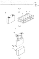
- Fig. 8 is a battery module 4 as an example.
- a plurality of secondary batteries 5 may be arranged in sequence along the length direction of the battery module 4. Hence, it can also be arranged in any other manner. Further, the plurality of secondary batteries 5 may be fixed by fasteners.
- the battery module 4 may further comprise a housing with a receiving space, and a plurality of secondary batteries 5 are accommodated in the receiving space.
- the above-mentioned battery module may also be assembled into a battery pack.
- the number of battery modules contained in the battery pack can be adjusted according to the application and capacity of the battery pack.
- Figs. 9 and 10 are the battery pack 1 as an example.
- the battery pack 1 may comprise a battery cabinet and a plurality of battery modules 4 provided in the battery cabinet.
- the battery cabinet comprises an upper cabinet 2 and a lower cabinet 3.
- the upper cabinet 2 can be covered on the lower cabinet 3 to form a closed space for accommodating the battery modules 4.
- the plurality of battery modules 4 may be arranged in the battery box in any manner.
- Embodiments of the present application provide an electric equipment, comprising the electrochemical device as described in the present application.
- the electrochemical device may be used as a powder source of the electric equipment, and may also be used as an energy storage unit of the electric equipment.
- the electric equipment may be, but is not limited to, a mobile device (for example, a mobile phone or a notebook computer), an electric vehicle (for example, a full electric vehicle, a hybrid electric vehicle, a plug-in hybrid electric vehicle, an electric bicycle, an electric scooter, an electric golf vehicle, or an electric truck), an electric train, a ship, a satellite, an energy storage system, and the like.
- the electrochemical device for example, a primary battery, a secondary battery, a battery module, or a battery pack, may be selected according to requirements for using the electric equipment.
- Fig. 11 shows an example of electric equipment.
- the electric equipment is a full electric vehicle, a hybrid electric vehicle, a plug-in hybrid electric vehicle, or the like.
- a battery pack or a battery module may be used.
- the electric equipment may be a mobile phone, a tablet computer, a notebook computer, or the like.
- the electric equipment usually requires lightness and thinness, and a secondary battery may be used as a power source.
- Preparation of a slurry for an overcharge blocking activation layer 53 parts by weight of polyvinylidene fluoride (PVDF), 7 parts of conductive carbon black (Super-P), 38 parts by weight of glucose pentaacetate, and 2 parts by weight of polyoxypropylene glycerol ether were placed in a planetary stirred tank. Then 900 parts by weight of N-methylpyrrolidone (NMP) were added as a dispersing solvent. After stirring quickly for 5 hours, a uniform and stable slurry was formed.
- PVDF polyvinylidene fluoride
- Super-P conductive carbon black
- Preparation of positive electrode current collector The uniform and stable slurry was vacuumed to remove bubbles, then applied on surfaces of metal conductive layer of aluminum foil on both sides with a gravure or micro gravure coater. After baking and drying, a uniform and dense overcharge blocking activation layer was formed, yielding a positive electrode current collector.
- the metal conductive layer of aluminum foil had a thickness of 12 ⁇ m, and the overcharge blocking activation layer on single side had a thickness of 3 ⁇ m.
- a positive electrode active material LiNi 0.8 Co 0.1 Mn 0.1 O 2 , a conductive agent Super-P, a binder PVDF were dispersed at a weight ratio of 95:2:3 in a solvent NMP, to obtain a mixture. After stirring and mixing thoroughly, a positive electrode slurry was obtained. The positive electrode slurry was coated on two opposite surfaces of the positive electrode current collector. A positive electrode plate was obtained by drying and cold-pressing. On a single side of metal conductive layer, a ratio S 1 /S 2 of surface area S 1 of overcharge blocking activation layer to surface area S 1 of positive electrode active material layer was 1. The coverage of the overcharge blocking activation layer on the positive electrode active material layer was 100%.
- a negative electrode active material artificial graphite, a conductive agent Super-P, a binder styrene-butadiene rubber (SBR) and sodium carboxymethyl cellulose (CMC-Na) were dispersed at a weight ratio of 93:3:2:2 in deionized water as a solvent, to obtain a mixture. After stirring and mixing uniformly, a negative electrode slurry was obtained. Then the negative electrode slurry was coated on two opposite surfaces of the negative electrode current collector of copper foil. A negative electrode plate was obtained by drying and cold-pressing.
- Ethylene carbonate (EC), propylene carbonate (PC) and dimethyl carbonate (DMC) were mixed uniformly in a mass ratio of 1:1:1 to obtain an organic solvent. Then, lithium salt LiPF 6 was dissolved in the above organic solvent. After mixing uniformly, an electrolyte having a LiPF 6 concentration of 1 mol/L was obtained.
- the positive electrode plate, a porous polyethylene separator, and the negative electrode plate were stacked in order, and then wound to obtain a bare core.
- the bare core was placed in an outer package.
- the electrolyte was injected. After packaging, lithium ion secondary battery was obtained.
- Example 2 was different from Example 1 in that: 34 parts by weight of glucose-1,6-di(ethyl phosphate) were used as overcharge blocking activation material; 53 parts by weight of PVDF were used as a binder; 7 parts by weight of conductive carbon black (Super-P) and 1 parts by weight of carbon nanotubes (CNT) were used as conductive agent; and 3 parts by weight of vinyltrimethoxysilane and 2 parts by weight of polyoxypropylene glycerol ether were used as auxiliary material.
- 34 parts by weight of glucose-1,6-di(ethyl phosphate) were used as overcharge blocking activation material
- 53 parts by weight of PVDF were used as a binder
- 7 parts by weight of conductive carbon black (Super-P) and 1 parts by weight of carbon nanotubes (CNT) were used as conductive agent
- 3 parts by weight of vinyltrimethoxysilane and 2 parts by weight of polyoxypropylene glycerol ether were used as auxiliary material.
- Example 3 was different from Example 1 in that: 37 parts by weight of glucose-1,6-di(methyl phosphate) were used as overcharge blocking activation material; 52 parts by weight of PVDF were used as a binder; 5 parts by weight of Super-P and 1 parts by weight of CNT were used as conductive agent; and 3 parts by weight of vinyltrimethoxysilane and 2 parts by weight of polyoxypropylene glycerol ether were used as auxiliary material.
- Example 4 was different from Example 1 in that: 36 parts by weight of ⁇ -cyclodextrin acetate were used as overcharge blocking activation material; 52 parts by weight of PVDF were used as a binder; 7 parts by weight of Super-P were used as conductive agent; and 3 parts by weight of vinyltrimethoxysilane and 2 parts by weight of polyoxypropylene glycerol ether were used as auxiliary material.
- Example 5 was different from Example 4 in that: the overcharge blocking activation layer on each single side has a thickness of 2 ⁇ m.
- Example 6 was different from Example 1 in that: 36 parts by weight of ⁇ -cyclodextrin carbonate were used as overcharge blocking activation material; 52 parts by weight of PVDF were used as a binder; 7 parts by weight of Super-P were used as conductive agent; and 3 parts by weight of vinyltrimethoxysilane and 2 parts by weight of polyoxypropylene glycerol ether were used as auxiliary material.
- Example 7 was different from Example 6 in that: the overcharge blocking activation layer on each single side has a thickness of 5 ⁇ m.
- Example 8 was different from Example 1 in that: 36 parts by weight of ⁇ -cyclodextrin phosphate were used as overcharge blocking activation material; 52 parts by weight of PVDF were used as a binder; 7 parts by weight of Super-P were used as conductive agent; and 3 parts by weight of vinyltrimethoxysilane and 2 parts by weight of polyoxypropylene glycerol ether were used as auxiliary material.
- Example 9 was different from Example 8 in that: the overcharge blocking activation layer on each single side has a thickness of 7 ⁇ m.
- Example 10 was different from Example 1 in that: 35 parts by weight of cellulose methyl carbonate were used as overcharge blocking activation material; 50 parts by weight of SBR were used as a binder; 10 parts by weight of Super-P were used as conductive agent; 5 parts by weight of CMC-Na were used as auxiliary material; and deionized water was used as solvent for dispersion.
- Example 11 was different from Example 1 in that: 35 parts by weight of chitosan methyl carbonate were used as overcharge blocking activation material; 50 parts by weight of PVDF were used as a binder; 10 parts by weight of Super-P were used as conductive agent; 3 parts by weight of vinyltrimethoxysilane and 2 parts by weight of polyoxypropylene glycerol ether were used as auxiliary material.
- Example 12 was different from Example 1 in that: 40 parts by weight of cellulose methyl carbonate were used as overcharge blocking activation material; 50 parts by weight of PVDF were used as a binder; 8 parts by weight of Super-P and 2 parts by weight of CNT were used as conductive agent; no auxiliary material was used.
- Example 13 was different from Example 1 in that: 35 parts by weight of cellulose methyl carbonate were used as overcharge blocking activation material; 53 parts by weight of PAA were used as a binder; 7 parts by weight of Super-P were used as conductive agent; 3 parts by weight of vinyltrimethoxysilane and 2 parts by weight of polyoxypropylene glycerol ether were used as auxiliary material; deionized water was used as solvent for dispersion; and on a single side of metal conductive layer, a ratio S 1 /S 2 of surface area S 1 of overcharge blocking activation layer to surface area S 1 of positive electrode active material layer was 98%.
- Example 14 was different from Example 1 in that: 35 parts by weight of cellulose methyl carbonate were used as overcharge blocking activation material; 53 parts by weight of PVDF were used as a binder; 5 parts by weight of Super-P and 2 parts by weight of CNT were used as conductive agent; 3 parts by weight of vinyltrimethoxysilane and 2 parts by weight of polyoxypropylene glycerol ether were used as auxiliary material; and the overcharge blocking activation layer on each single side has a thickness of 0.5 ⁇ m.
- Example 15 was different from Example 1 in that: 35 parts by weight of cellulose methyl carbonate were used as overcharge blocking activation material; 53 parts by weight of PVDF were used as a binder; 7 parts by weight of Super-P were used as conductive agent; and 3 parts by weight of vinyltrimethoxysilane and 2 parts by weight of polyoxypropylene glycerol ether were used as auxiliary material.
- Example 16 was different from Example 5 in that: the slurry for overcharge blocking activation layer was applied on surface of metal conductive layer of aluminum foil on single side, and after baking and drying, a uniform and dense overcharge blocking activation layer was formed, yielding a positive electrode current collector; the metal conductive layer of aluminum foil had a thickness of 12 ⁇ m, and the overcharge blocking activation layer had a thickness of 10 ⁇ m.
- Example 17 was different from Example 1 in that: 35 parts by weight of cellulose methyl carbonate were used as overcharge blocking activation material; 53 parts by weight of PVDF were used as a binder; 5 parts by weight of Super-P and 2 parts by weight of CNT were used as conductive agent; 3 parts by weight of vinyltrimethoxysilane and 2 parts by weight of polyoxypropylene glycerol ether were used as auxiliary material; and LiCoO 2 was used as positive electrode active material.
- Comparative Example 1 was different from Example 1 in that: aluminum foil having a thickness of 12 ⁇ m was used as a positive electrode current collector, without an overcharge blocking activation layer.
- Comparative Example 2 was different from Example 1 in that: a positive electrode current collector comprises a conductive layer of aluminum foil having a thickness of 12 ⁇ m and coatings disposed on two opposite surfaces of the conductive layer of aluminum foil; and slurry for coatings was prepared as follows: 5 parts by weight of CMC-Na, 85 parts by weight of SBR, and 10 parts by weight of Super-P were placed in a planetary stirred tank, then 900 parts by weight of deionized water were added as a dispersing solvent, and after stirring quickly for 5 hours, a uniform and stable slurry was formed. Other steps were the same as those in Example 1.
- Comparative Example 3 was different from Example 1 in that: a positive electrode current collector comprises a conductive layer of aluminum foil having a thickness of 12 ⁇ m and coatings disposed on two opposite surfaces of the conductive layer of aluminum foil; and slurry for coatings was prepared as follows: 90 parts by weight of PAA and 10 parts by weight of SBR were placed in a planetary stirred tank, then 900 parts by weight of deionized water were added as a dispersing solvent, and after stirring quickly for 5 hours, a uniform and stable slurry was formed. Other steps were the same as those in Example 1.
- Comparative Example 4 was different from Example 1 in that: a positive electrode current collector comprises a conductive layer of aluminum foil having a thickness of 12 ⁇ m and coatings disposed on two opposite surfaces of the conductive layer of aluminum foil; and slurry for coatings was prepared as follows: 90 parts by weight of PVDF and 10 parts by weight of Super-P were placed in a planetary stirred tank, then 900 parts by weight of NMP were added as a dispersing solvent, and after stirring quickly for 5 hours, a uniform and stable slurry was formed. Other steps were the same as those in Example 1.
- Comparative Example 5 was different from Example 17 in that: aluminum foil having a thickness of 12 ⁇ m was used as a positive electrode current collector, without an overcharge blocking activation layer.
- Comparative Example 6 was different from Example 17 in that: a positive electrode current collector comprises a conductive layer of aluminum foil having a thickness of 12 ⁇ m and coatings disposed on two opposite surfaces of the conductive layer of aluminum foil; and slurry for coatings was prepared as follows: 90 parts by weight of PVDF and 10 parts by weight of Super-P were placed in a planetary stirred tank, then 900 parts by weight of NMP were added as a dispersing solvent, and after stirring quickly for 5 hours, a uniform and stable slurry was formed. Other steps were the same as those in Example 14.
- the lithium ion secondary battery was charged at a constant current rate of 0.1C to 4.25V, and then charged at a constant voltage to a current of 0.05C, and was left for 30 minutes. Then, the battery was fixed with a clamp and placed on overcharge safety testing equipment. At the ambient temperature controlled at 25 ⁇ 2°C, the battery was left for 5 minutes. Then, fully charged battery was charged at a constant current rate of 1C. real-time voltage and temperature changes were record for each battery, until the battery cached fire or exploded or the charging step was stopped. For each of Examples and Comparative Examples, 10 batteries were taken for testing. If a battery did not catch fire or exploded, the battery passed the test; otherwise, it failed the test.
- the lithium ion secondary battery was charged at a constant current rate of 0.1C to 4.25V, and then charged at a constant voltage to a current of 0.05C, and was left for 5 minutes, then discharged at a constant current of 1C until a voltage of 2.8 was reached. This was regarded as a charge/discharge cycle process, and the obtained discharge capacity at this time was the discharge capacity at the first cycle.
- the lithium ion secondary battery was subjected to charge/discharge test according to the foregoing method for 100 cycles, to record the discharge capacity values for each cycle.
- Capacity retention rate (%) (the discharge capacity at the 100th cycle/the discharge capacity of the lithium ion battery at the first cycle) ⁇ 100%.
- Example 1-17 EX1-EX17
- Comparative Examples 1-6 CE1-CE6
- Table 1 Pass rate in test of overcharge safety performance Capacity retention rate at 100 cycles (%)
- Example 1 7/10 91.3 Example 2 9/10 91.5
- Example 3 10/10 91.1
- Example 4 8/10 93.7
- Example 5 7/10 94.0
- Example 6 10/10 93.6
- Example 7 10/10 92.8
- Example 8 10/10 93.8
- Example 9 10/10 91.9
- Example 10/10 94.2 Example 11 10/10 94.5
- Example 12 6/10 94.1
- Example 13 8/10 94.6
- Example 14 5/10 94.7
- Example 15 10/10 94.3
- Example 16 10/10 94.3
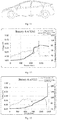
- Fig. 13 is a graph of voltage-temperature-time of the lithium ion secondary battery of Comparative Example 1.
- Fig. 12 is a graph of voltage-temperature-time of the lithium ion secondary battery of Example 1.
- the overcharge blocking activation layer rapidly responded and cut off external charging current and suppressed the increase of the battery temperature, thereby significantly improving the overcharge safety performance of the battery. From comparison between Fig. 12 and Fig. 13 , it can be seen that the overcharge safety performance of the lithium ion secondary battery is significantly improved by disposing an overcharge blocking activation layer in positive electrode current collector.
- the overcharge blocking activation layer can cut off external charging current in time by disposing an overcharge blocking activation layer in positive electrode current collector, so that the overcharge safety performance of the battery is significantly improved; in addition, cycle performance of lithium ion secondary battery that is charged and discharged under normal circumstances is not significantly influenced, so that a relatively high capacity retention rate is maintained.
Landscapes
- Chemical & Material Sciences (AREA)
- Electrochemistry (AREA)
- General Chemical & Material Sciences (AREA)
- Chemical Kinetics & Catalysis (AREA)
- Engineering & Computer Science (AREA)
- Materials Engineering (AREA)
- Composite Materials (AREA)
- Manufacturing & Machinery (AREA)
- Inorganic Chemistry (AREA)
- Secondary Cells (AREA)
- Battery Electrode And Active Subsutance (AREA)
- Electric Double-Layer Capacitors Or The Like (AREA)
- Cell Electrode Carriers And Collectors (AREA)
Applications Claiming Priority (2)
| Application Number | Priority Date | Filing Date | Title |
|---|---|---|---|
| CN201910441399.XA CN110265665B (zh) | 2019-05-24 | 2019-05-24 | 正极集流体、正极极片及电化学装置 |
| PCT/CN2020/086974 WO2020238521A1 (zh) | 2019-05-24 | 2020-04-26 | 正极集流体、正极极片、电化学装置和包含该电化学装置的用电设备 |
Publications (3)
| Publication Number | Publication Date |
|---|---|
| EP3809502A1 true EP3809502A1 (de) | 2021-04-21 |
| EP3809502A4 EP3809502A4 (de) | 2021-10-06 |
| EP3809502B1 EP3809502B1 (de) | 2022-09-07 |
Family
ID=67915415
Family Applications (1)
| Application Number | Title | Priority Date | Filing Date |
|---|---|---|---|
| EP20814019.4A Active EP3809502B1 (de) | 2019-05-24 | 2020-04-26 | Positivelektrodenstromkollektor, positivelektrodenplatte, elektrochemische vorrichtung und elektrische einrichtung mit elektrochemischer vorrichtung |
Country Status (5)
| Country | Link |
|---|---|
| US (1) | US11158859B2 (de) |
| EP (1) | EP3809502B1 (de) |
| CN (1) | CN110265665B (de) |
| ES (1) | ES2928725T3 (de) |
| WO (1) | WO2020238521A1 (de) |
Cited By (3)
| Publication number | Priority date | Publication date | Assignee | Title |
|---|---|---|---|---|
| EP3979397A4 (de) * | 2019-08-08 | 2022-07-27 | Contemporary Amperex Technology Co., Limited | Positive elektrodenplatte und elektrochemische vorrichtung sowie zugehörige ausrüstung |
| US11973196B2 (en) | 2019-08-08 | 2024-04-30 | Contemporary Amperex Technology Co., Limited | Positive electrode plate, and electrochemical apparatus and device associated therewith |
| WO2025214813A1 (en) | 2024-04-12 | 2025-10-16 | Boosting Innovation In Poliba S.C. A R.L. | Bio-based polymer-carbon composite formulation for electrodes and electrochemical energy conversion and storage devices |
Families Citing this family (13)
| Publication number | Priority date | Publication date | Assignee | Title |
|---|---|---|---|---|
| CN109817871A (zh) * | 2019-03-29 | 2019-05-28 | 溧阳天目先导电池材料科技有限公司 | 一种离子导体浆料及其制备方法和应用 |
| CN110265665B (zh) * | 2019-05-24 | 2020-11-17 | 宁德时代新能源科技股份有限公司 | 正极集流体、正极极片及电化学装置 |
| CN110444764B (zh) * | 2019-08-08 | 2020-12-22 | 宁德时代新能源科技股份有限公司 | 一种正极极片及电化学储能装置 |
| CN110474114B (zh) * | 2019-08-08 | 2020-11-10 | 宁德时代新能源科技股份有限公司 | 一种电化学储能装置 |
| CN112563661B (zh) * | 2020-12-07 | 2022-05-27 | 界首市天鸿新材料股份有限公司 | 环保型纤维素基隔膜的制备方法及其在锂电池中的应用 |
| EP4071865A4 (de) | 2021-02-06 | 2023-03-22 | Contemporary Amperex Technology Co., Limited | Sekundärbatterie und batteriemodul, batteriepack und vorrichtung damit |
| CA3238946A1 (en) * | 2021-12-02 | 2023-06-08 | Kam Piu Ho | Modified current collector for secondary battery |
| JP2025528506A (ja) * | 2022-09-06 | 2025-08-28 | 揚州納力新材料科技有限公司 | 複合ポリエステルフィルムおよびその製造方法と使用 |
| JP2025528525A (ja) * | 2022-09-06 | 2025-08-28 | 揚州納力新材料科技有限公司 | 複合ポリマーフィルム、その製造方法、金属化複合ポリマーフィルムおよび使用 |
| WO2025138091A1 (zh) * | 2023-12-29 | 2025-07-03 | 宁德新能源科技有限公司 | 正极极片、二次电池和电子设备 |
| CN118263449A (zh) * | 2024-04-22 | 2024-06-28 | 江阴纳力新材料科技有限公司 | 一种复合集流体及其制备方法和应用 |
| CN118825367A (zh) * | 2024-08-14 | 2024-10-22 | 宁德新能源科技有限公司 | 二次电池和电子装置 |
| CN119447300B (zh) * | 2024-10-29 | 2026-01-06 | 中南大学 | 一种锂离子电池正极材料的表面处理剂及其应用 |
Family Cites Families (20)
| Publication number | Priority date | Publication date | Assignee | Title |
|---|---|---|---|---|
| WO1999008335A1 (fr) * | 1997-08-11 | 1999-02-18 | Sony Corporation | Accumulateur electrique a electrolyte non aqueux |
| KR100276966B1 (ko) | 1998-07-31 | 2001-02-01 | 이병길 | 2차전지용 금속 알루미늄과 구리 집전체의 전처리 방법 |
| JP4201308B2 (ja) * | 2001-10-11 | 2008-12-24 | 株式会社豊田中央研究所 | リチウム二次電池用セパレータおよびそれを用いたリチウム二次電池 |
| KR100560546B1 (ko) * | 2003-11-27 | 2006-03-15 | 삼성에스디아이 주식회사 | 리튬 이차 전지용 음극 및 이를 포함하는 리튬 이차 전지 |
| BRPI0717388A2 (pt) * | 2006-10-23 | 2013-10-15 | Cook Biotech Inc | Materiais ecm processados com melhores perfis de componentes |
| WO2011030626A1 (ja) * | 2009-09-11 | 2011-03-17 | Jx日鉱日石金属株式会社 | リチウムイオン電池集電体用銅箔 |
| JP2011192568A (ja) * | 2010-03-16 | 2011-09-29 | Konica Minolta Holdings Inc | 電解質組成物、および二次電池 |
| KR20130043122A (ko) * | 2011-01-14 | 2013-04-29 | 쇼와 덴코 가부시키가이샤 | 집전체 |
| WO2013062334A1 (ko) * | 2011-10-25 | 2013-05-02 | 주식회사 엘지화학 | 이차전지용 음극 및 이를 구비하는 이차전지 |
| CN103280597B (zh) * | 2013-05-31 | 2017-09-29 | 宁德新能源科技有限公司 | 锂离子电池 |
| JP6589267B2 (ja) * | 2014-10-08 | 2019-10-16 | 凸版印刷株式会社 | リチウムイオン電池の正極電極の製造方法 |
| CN104409681A (zh) * | 2014-11-19 | 2015-03-11 | 上海航天电源技术有限责任公司 | 一种含ptc涂层的锂离子电池极片的制备方法 |
| US10020487B2 (en) * | 2014-11-25 | 2018-07-10 | American Lithium Energy Corporation | Rechargeable battery with voltage activated current interrupter |
| CN107437622B (zh) | 2016-05-26 | 2021-06-04 | 宁德时代新能源科技股份有限公司 | 电极及其制备方法 |
| JP7074284B2 (ja) * | 2017-02-10 | 2022-05-24 | 三井化学株式会社 | 正極及び非水電解質二次電池 |
| CN106910897A (zh) * | 2017-03-02 | 2017-06-30 | 宁德时代新能源科技股份有限公司 | 一种集流体及其极片和电池 |
| CN107565137B (zh) * | 2017-07-03 | 2020-06-23 | 北京卫蓝新能源科技有限公司 | 一种集流体及含有该集流体的极片、固态电池 |
| US10957956B2 (en) * | 2017-09-09 | 2021-03-23 | Soteria Battery Innovation Group, Inc. | Energy storage device having a current collector with inherent current limitations |
| CN109755462B (zh) * | 2017-11-08 | 2021-01-12 | 宁德时代新能源科技股份有限公司 | 一种正极极片、电化学装置及安全涂层 |
| CN110265665B (zh) * | 2019-05-24 | 2020-11-17 | 宁德时代新能源科技股份有限公司 | 正极集流体、正极极片及电化学装置 |
-
2019
- 2019-05-24 CN CN201910441399.XA patent/CN110265665B/zh active Active
-
2020
- 2020-04-26 ES ES20814019T patent/ES2928725T3/es active Active
- 2020-04-26 WO PCT/CN2020/086974 patent/WO2020238521A1/zh not_active Ceased
- 2020-04-26 EP EP20814019.4A patent/EP3809502B1/de active Active
-
2021
- 2021-01-15 US US17/149,736 patent/US11158859B2/en active Active
Cited By (4)
| Publication number | Priority date | Publication date | Assignee | Title |
|---|---|---|---|---|
| EP3979397A4 (de) * | 2019-08-08 | 2022-07-27 | Contemporary Amperex Technology Co., Limited | Positive elektrodenplatte und elektrochemische vorrichtung sowie zugehörige ausrüstung |
| US11894524B2 (en) | 2019-08-08 | 2024-02-06 | Contemporary Amperex Technology Co., Limited | Positive electrode plate, and electrochemical apparatus and device associated therewith |
| US11973196B2 (en) | 2019-08-08 | 2024-04-30 | Contemporary Amperex Technology Co., Limited | Positive electrode plate, and electrochemical apparatus and device associated therewith |
| WO2025214813A1 (en) | 2024-04-12 | 2025-10-16 | Boosting Innovation In Poliba S.C. A R.L. | Bio-based polymer-carbon composite formulation for electrodes and electrochemical energy conversion and storage devices |
Also Published As
| Publication number | Publication date |
|---|---|
| EP3809502B1 (de) | 2022-09-07 |
| US20210143436A1 (en) | 2021-05-13 |
| ES2928725T3 (es) | 2022-11-22 |
| CN110265665B (zh) | 2020-11-17 |
| EP3809502A4 (de) | 2021-10-06 |
| WO2020238521A1 (zh) | 2020-12-03 |
| US11158859B2 (en) | 2021-10-26 |
| CN110265665A (zh) | 2019-09-20 |
Similar Documents
| Publication | Publication Date | Title |
|---|---|---|
| EP3809502B1 (de) | Positivelektrodenstromkollektor, positivelektrodenplatte, elektrochemische vorrichtung und elektrische einrichtung mit elektrochemischer vorrichtung | |
| US11196041B2 (en) | Positive electrode plate and lithium-ion secondary battery | |
| KR20220036961A (ko) | 이차 전지, 이차 전지를 포함하는 전지 모듈, 전지 팩 및 장치 | |
| US20260074288A1 (en) | Lithium secondary battery and electrical apparatus | |
| EP4203112B1 (de) | Stromkollektor und herstellungsverfahren dafür, sekundärbatterie, batteriemodul, batteriepack und elektrische vorrichtung | |
| US20250070186A1 (en) | Positive electrode sheet, secondary battery, and electrical device | |
| EP4362156A1 (de) | Lithium-ionen-batterie, batteriemodul, batteriepack und elektrische vorrichtung | |
| EP4503173A1 (de) | Negativelektrodenplatte und herstellungsverfahren dafür, sekundärbatterie, batteriemodul, batteriepack und elektrische vorrichtung | |
| CN110474114A (zh) | 一种电化学储能装置 | |
| US20250349970A1 (en) | Secondary battery and electric apparatus | |
| EP4024532B1 (de) | Sekundärbatterie, herstellungsverfahren dafür, copolymer und vorrichtung | |
| KR20250004274A (ko) | 개선된 전해액 점도 및 cb값을 갖는 리튬 이온 전지 및 전기 장치 | |
| EP4231380A1 (de) | Negatives polstück und herstellungsverfahren dafür, sekundärbatterie, batteriemodul, batteriepack und elektrische vorrichtung | |
| CN115956308A (zh) | 锂离子二次电池、电池模块、电池包和用电装置 | |
| EP4207361A1 (de) | Negativelektrodenplatte, sekundärbatterie, batteriemodul, batteriepack und elektrische vorrichtung | |
| US11830981B2 (en) | Electrolyte and electrochemical device | |
| CN117501502A (zh) | 一种电解液、二次电池、电池模块、电池包和用电装置 | |
| US12160003B2 (en) | Electrode assembly and secondary battery comprising the same, battery module, battery pack and electrical device | |
| CN119230836B (zh) | 集流体及其制备方法、正极极片、二次电池和用电装置 | |
| EP4629323A1 (de) | Negativelektrodenfolie und herstellungsverfahren dafür, sekundärbatterie und elektrische vorrichtung | |
| EP4280302A1 (de) | Sekundärbatterie, herstellungsverfahren für zugehöriges positivelektrodenaktivmaterial, batteriemodul, batteriepack und elektrische vorrichtung | |
| EP4604216A1 (de) | Zusammengesetztes positivelektrodenaktivmaterial, batteriezelle, batterie und elektrische vorrichtung | |
| US20250192189A1 (en) | Secondary battery and electrical apparatus | |
| EP4611099A1 (de) | Lithium-ionen-batterie mit dotiertem positivem elektrodenaktivmaterial | |
| EP4318715A1 (de) | Sekundärbatterie mit silikatester und elektrische vorrichtung |
Legal Events
| Date | Code | Title | Description |
|---|---|---|---|
| STAA | Information on the status of an ep patent application or granted ep patent |
Free format text: STATUS: THE INTERNATIONAL PUBLICATION HAS BEEN MADE |
|
| PUAI | Public reference made under article 153(3) epc to a published international application that has entered the european phase |
Free format text: ORIGINAL CODE: 0009012 |
|
| STAA | Information on the status of an ep patent application or granted ep patent |
Free format text: STATUS: REQUEST FOR EXAMINATION WAS MADE |
|
| 17P | Request for examination filed |
Effective date: 20210115 |
|
| AK | Designated contracting states |
Kind code of ref document: A1 Designated state(s): AL AT BE BG CH CY CZ DE DK EE ES FI FR GB GR HR HU IE IS IT LI LT LU LV MC MK MT NL NO PL PT RO RS SE SI SK SM TR |
|
| AX | Request for extension of the european patent |
Extension state: BA ME |
|
| A4 | Supplementary search report drawn up and despatched |
Effective date: 20210906 |
|
| RIC1 | Information provided on ipc code assigned before grant |
Ipc: H01M 4/131 20100101ALI20210831BHEP Ipc: H01M 10/42 20060101ALI20210831BHEP Ipc: H01M 10/0525 20100101ALI20210831BHEP Ipc: H01M 4/66 20060101AFI20210831BHEP |
|
| GRAP | Despatch of communication of intention to grant a patent |
Free format text: ORIGINAL CODE: EPIDOSNIGR1 |
|
| STAA | Information on the status of an ep patent application or granted ep patent |
Free format text: STATUS: GRANT OF PATENT IS INTENDED |
|
| INTG | Intention to grant announced |
Effective date: 20220524 |
|
| GRAS | Grant fee paid |
Free format text: ORIGINAL CODE: EPIDOSNIGR3 |
|
| GRAA | (expected) grant |
Free format text: ORIGINAL CODE: 0009210 |
|
| STAA | Information on the status of an ep patent application or granted ep patent |
Free format text: STATUS: THE PATENT HAS BEEN GRANTED |
|
| DAV | Request for validation of the european patent (deleted) | ||
| DAX | Request for extension of the european patent (deleted) | ||
| AK | Designated contracting states |
Kind code of ref document: B1 Designated state(s): AL AT BE BG CH CY CZ DE DK EE ES FI FR GB GR HR HU IE IS IT LI LT LU LV MC MK MT NL NO PL PT RO RS SE SI SK SM TR |
|
| REG | Reference to a national code |
Ref country code: GB Ref legal event code: FG4D |
|
| REG | Reference to a national code |
Ref country code: CH Ref legal event code: EP Ref country code: AT Ref legal event code: REF Ref document number: 1517804 Country of ref document: AT Kind code of ref document: T Effective date: 20220915 |
|
| REG | Reference to a national code |
Ref country code: IE Ref legal event code: FG4D |
|
| REG | Reference to a national code |
Ref country code: DE Ref legal event code: R096 Ref document number: 602020005034 Country of ref document: DE |
|
| REG | Reference to a national code |
Ref country code: SE Ref legal event code: TRGR |
|
| REG | Reference to a national code |
Ref country code: NL Ref legal event code: FP |
|
| REG | Reference to a national code |
Ref country code: ES Ref legal event code: FG2A Ref document number: 2928725 Country of ref document: ES Kind code of ref document: T3 Effective date: 20221122 |
|
| REG | Reference to a national code |
Ref country code: LT Ref legal event code: MG9D |
|
| PG25 | Lapsed in a contracting state [announced via postgrant information from national office to epo] |
Ref country code: RS Free format text: LAPSE BECAUSE OF FAILURE TO SUBMIT A TRANSLATION OF THE DESCRIPTION OR TO PAY THE FEE WITHIN THE PRESCRIBED TIME-LIMIT Effective date: 20220907 Ref country code: NO Free format text: LAPSE BECAUSE OF FAILURE TO SUBMIT A TRANSLATION OF THE DESCRIPTION OR TO PAY THE FEE WITHIN THE PRESCRIBED TIME-LIMIT Effective date: 20221207 Ref country code: LV Free format text: LAPSE BECAUSE OF FAILURE TO SUBMIT A TRANSLATION OF THE DESCRIPTION OR TO PAY THE FEE WITHIN THE PRESCRIBED TIME-LIMIT Effective date: 20220907 Ref country code: LT Free format text: LAPSE BECAUSE OF FAILURE TO SUBMIT A TRANSLATION OF THE DESCRIPTION OR TO PAY THE FEE WITHIN THE PRESCRIBED TIME-LIMIT Effective date: 20220907 Ref country code: FI Free format text: LAPSE BECAUSE OF FAILURE TO SUBMIT A TRANSLATION OF THE DESCRIPTION OR TO PAY THE FEE WITHIN THE PRESCRIBED TIME-LIMIT Effective date: 20220907 |
|
| REG | Reference to a national code |
Ref country code: AT Ref legal event code: MK05 Ref document number: 1517804 Country of ref document: AT Kind code of ref document: T Effective date: 20220907 |
|
| PG25 | Lapsed in a contracting state [announced via postgrant information from national office to epo] |
Ref country code: HR Free format text: LAPSE BECAUSE OF FAILURE TO SUBMIT A TRANSLATION OF THE DESCRIPTION OR TO PAY THE FEE WITHIN THE PRESCRIBED TIME-LIMIT Effective date: 20220907 Ref country code: GR Free format text: LAPSE BECAUSE OF FAILURE TO SUBMIT A TRANSLATION OF THE DESCRIPTION OR TO PAY THE FEE WITHIN THE PRESCRIBED TIME-LIMIT Effective date: 20221208 |
|
| PG25 | Lapsed in a contracting state [announced via postgrant information from national office to epo] |
Ref country code: SM Free format text: LAPSE BECAUSE OF FAILURE TO SUBMIT A TRANSLATION OF THE DESCRIPTION OR TO PAY THE FEE WITHIN THE PRESCRIBED TIME-LIMIT Effective date: 20220907 Ref country code: RO Free format text: LAPSE BECAUSE OF FAILURE TO SUBMIT A TRANSLATION OF THE DESCRIPTION OR TO PAY THE FEE WITHIN THE PRESCRIBED TIME-LIMIT Effective date: 20220907 Ref country code: PT Free format text: LAPSE BECAUSE OF FAILURE TO SUBMIT A TRANSLATION OF THE DESCRIPTION OR TO PAY THE FEE WITHIN THE PRESCRIBED TIME-LIMIT Effective date: 20230109 Ref country code: CZ Free format text: LAPSE BECAUSE OF FAILURE TO SUBMIT A TRANSLATION OF THE DESCRIPTION OR TO PAY THE FEE WITHIN THE PRESCRIBED TIME-LIMIT Effective date: 20220907 Ref country code: AT Free format text: LAPSE BECAUSE OF FAILURE TO SUBMIT A TRANSLATION OF THE DESCRIPTION OR TO PAY THE FEE WITHIN THE PRESCRIBED TIME-LIMIT Effective date: 20220907 |
|
| PG25 | Lapsed in a contracting state [announced via postgrant information from national office to epo] |
Ref country code: SK Free format text: LAPSE BECAUSE OF FAILURE TO SUBMIT A TRANSLATION OF THE DESCRIPTION OR TO PAY THE FEE WITHIN THE PRESCRIBED TIME-LIMIT Effective date: 20220907 Ref country code: PL Free format text: LAPSE BECAUSE OF FAILURE TO SUBMIT A TRANSLATION OF THE DESCRIPTION OR TO PAY THE FEE WITHIN THE PRESCRIBED TIME-LIMIT Effective date: 20220907 Ref country code: IS Free format text: LAPSE BECAUSE OF FAILURE TO SUBMIT A TRANSLATION OF THE DESCRIPTION OR TO PAY THE FEE WITHIN THE PRESCRIBED TIME-LIMIT Effective date: 20230107 Ref country code: EE Free format text: LAPSE BECAUSE OF FAILURE TO SUBMIT A TRANSLATION OF THE DESCRIPTION OR TO PAY THE FEE WITHIN THE PRESCRIBED TIME-LIMIT Effective date: 20220907 |
|
| REG | Reference to a national code |
Ref country code: DE Ref legal event code: R097 Ref document number: 602020005034 Country of ref document: DE |
|
| P01 | Opt-out of the competence of the unified patent court (upc) registered |
Effective date: 20230516 |
|
| PG25 | Lapsed in a contracting state [announced via postgrant information from national office to epo] |
Ref country code: AL Free format text: LAPSE BECAUSE OF FAILURE TO SUBMIT A TRANSLATION OF THE DESCRIPTION OR TO PAY THE FEE WITHIN THE PRESCRIBED TIME-LIMIT Effective date: 20220907 |
|
| PLBE | No opposition filed within time limit |
Free format text: ORIGINAL CODE: 0009261 |
|
| STAA | Information on the status of an ep patent application or granted ep patent |
Free format text: STATUS: NO OPPOSITION FILED WITHIN TIME LIMIT |
|
| PG25 | Lapsed in a contracting state [announced via postgrant information from national office to epo] |
Ref country code: DK Free format text: LAPSE BECAUSE OF FAILURE TO SUBMIT A TRANSLATION OF THE DESCRIPTION OR TO PAY THE FEE WITHIN THE PRESCRIBED TIME-LIMIT Effective date: 20220907 |
|
| 26N | No opposition filed |
Effective date: 20230608 |
|
| PG25 | Lapsed in a contracting state [announced via postgrant information from national office to epo] |
Ref country code: SI Free format text: LAPSE BECAUSE OF FAILURE TO SUBMIT A TRANSLATION OF THE DESCRIPTION OR TO PAY THE FEE WITHIN THE PRESCRIBED TIME-LIMIT Effective date: 20220907 |
|
| REG | Reference to a national code |
Ref country code: CH Ref legal event code: PL |
|
| PG25 | Lapsed in a contracting state [announced via postgrant information from national office to epo] |
Ref country code: LU Free format text: LAPSE BECAUSE OF NON-PAYMENT OF DUE FEES Effective date: 20230426 |
|
| PG25 | Lapsed in a contracting state [announced via postgrant information from national office to epo] |
Ref country code: MC Free format text: LAPSE BECAUSE OF FAILURE TO SUBMIT A TRANSLATION OF THE DESCRIPTION OR TO PAY THE FEE WITHIN THE PRESCRIBED TIME-LIMIT Effective date: 20220907 |
|
| PG25 | Lapsed in a contracting state [announced via postgrant information from national office to epo] |
Ref country code: MC Free format text: LAPSE BECAUSE OF FAILURE TO SUBMIT A TRANSLATION OF THE DESCRIPTION OR TO PAY THE FEE WITHIN THE PRESCRIBED TIME-LIMIT Effective date: 20220907 Ref country code: LI Free format text: LAPSE BECAUSE OF NON-PAYMENT OF DUE FEES Effective date: 20230430 Ref country code: CH Free format text: LAPSE BECAUSE OF NON-PAYMENT OF DUE FEES Effective date: 20230430 |
|
| REG | Reference to a national code |
Ref country code: IE Ref legal event code: MM4A |
|
| PG25 | Lapsed in a contracting state [announced via postgrant information from national office to epo] |
Ref country code: IE Free format text: LAPSE BECAUSE OF NON-PAYMENT OF DUE FEES Effective date: 20230426 |
|
| PG25 | Lapsed in a contracting state [announced via postgrant information from national office to epo] |
Ref country code: IE Free format text: LAPSE BECAUSE OF NON-PAYMENT OF DUE FEES Effective date: 20230426 |
|
| PG25 | Lapsed in a contracting state [announced via postgrant information from national office to epo] |
Ref country code: IT Free format text: LAPSE BECAUSE OF FAILURE TO SUBMIT A TRANSLATION OF THE DESCRIPTION OR TO PAY THE FEE WITHIN THE PRESCRIBED TIME-LIMIT Effective date: 20220907 |
|
| REG | Reference to a national code |
Ref country code: DE Ref legal event code: R081 Ref document number: 602020005034 Country of ref document: DE Owner name: CONTEMPORARY AMPEREX TECHNOLOGY (HONG KONG) LI, HK Free format text: FORMER OWNER: CONTEMPORARY AMPEREX TECHNOLOGY CO., LIMITED, NINGDE CITY, FUJIAN, CN |
|
| REG | Reference to a national code |
Ref country code: NL Ref legal event code: PD Owner name: CONTEMPORARY AMPEREX TECHNOLOGY (HONG KONG) LIMITED; CN Free format text: DETAILS ASSIGNMENT: CHANGE OF OWNER(S), ASSIGNMENT; FORMER OWNER NAME: CONTEMPORARY AMPEREX TECHNOLOGY CO., LIMITED Effective date: 20240819 |
|
| REG | Reference to a national code |
Ref country code: GB Ref legal event code: 732E Free format text: REGISTERED BETWEEN 20240829 AND 20240904 |
|
| PG25 | Lapsed in a contracting state [announced via postgrant information from national office to epo] |
Ref country code: BG Free format text: LAPSE BECAUSE OF FAILURE TO SUBMIT A TRANSLATION OF THE DESCRIPTION OR TO PAY THE FEE WITHIN THE PRESCRIBED TIME-LIMIT Effective date: 20220907 |
|
| PG25 | Lapsed in a contracting state [announced via postgrant information from national office to epo] |
Ref country code: BG Free format text: LAPSE BECAUSE OF FAILURE TO SUBMIT A TRANSLATION OF THE DESCRIPTION OR TO PAY THE FEE WITHIN THE PRESCRIBED TIME-LIMIT Effective date: 20220907 |
|
| REG | Reference to a national code |
Ref country code: ES Ref legal event code: PC2A Owner name: CONTEMPORARY AMPEREX TECHNOLOGY (HONG KONG) LIMITED Effective date: 20241129 |
|
| REG | Reference to a national code |
Ref country code: BE Ref legal event code: PD Owner name: CONTEMPORARY AMPEREX TECHNOLOGY (HONG KONG) LIMITED; CN Free format text: DETAILS ASSIGNMENT: CHANGE OF OWNER(S), ASSIGNMENT; FORMER OWNER NAME: CONTEMPORARY AMPEREX TECHNOLOGY CO., LIMITED Effective date: 20240807 |
|
| PGFP | Annual fee paid to national office [announced via postgrant information from national office to epo] |
Ref country code: DE Payment date: 20250305 Year of fee payment: 6 |
|
| PGFP | Annual fee paid to national office [announced via postgrant information from national office to epo] |
Ref country code: ES Payment date: 20250508 Year of fee payment: 6 |
|
| PG25 | Lapsed in a contracting state [announced via postgrant information from national office to epo] |
Ref country code: CY Free format text: LAPSE BECAUSE OF FAILURE TO SUBMIT A TRANSLATION OF THE DESCRIPTION OR TO PAY THE FEE WITHIN THE PRESCRIBED TIME-LIMIT; INVALID AB INITIO Effective date: 20200426 |
|
| PG25 | Lapsed in a contracting state [announced via postgrant information from national office to epo] |
Ref country code: HU Free format text: LAPSE BECAUSE OF FAILURE TO SUBMIT A TRANSLATION OF THE DESCRIPTION OR TO PAY THE FEE WITHIN THE PRESCRIBED TIME-LIMIT; INVALID AB INITIO Effective date: 20200426 |
|
| PG25 | Lapsed in a contracting state [announced via postgrant information from national office to epo] |
Ref country code: TR Free format text: LAPSE BECAUSE OF FAILURE TO SUBMIT A TRANSLATION OF THE DESCRIPTION OR TO PAY THE FEE WITHIN THE PRESCRIBED TIME-LIMIT Effective date: 20220907 |
|
| PGFP | Annual fee paid to national office [announced via postgrant information from national office to epo] |
Ref country code: SE Payment date: 20260312 Year of fee payment: 7 |
|
| PGFP | Annual fee paid to national office [announced via postgrant information from national office to epo] |
Ref country code: GB Payment date: 20260310 Year of fee payment: 7 |
|
| PGFP | Annual fee paid to national office [announced via postgrant information from national office to epo] |
Ref country code: BE Payment date: 20260317 Year of fee payment: 7 |
|
| PGFP | Annual fee paid to national office [announced via postgrant information from national office to epo] |
Ref country code: NL Payment date: 20260317 Year of fee payment: 7 |
|
| PGFP | Annual fee paid to national office [announced via postgrant information from national office to epo] |
Ref country code: FR Payment date: 20260309 Year of fee payment: 7 |