EP3807201B1 - Organising system and machine for treating sheet-shaped elements - Google Patents
Organising system and machine for treating sheet-shaped elements Download PDFInfo
- Publication number
- EP3807201B1 EP3807201B1 EP19720369.8A EP19720369A EP3807201B1 EP 3807201 B1 EP3807201 B1 EP 3807201B1 EP 19720369 A EP19720369 A EP 19720369A EP 3807201 B1 EP3807201 B1 EP 3807201B1
- Authority
- EP
- European Patent Office
- Prior art keywords
- storage surface
- control profile
- storage
- storage device
- retracted position
- Prior art date
- Legal status (The legal status is an assumption and is not a legal conclusion. Google has not performed a legal analysis and makes no representation as to the accuracy of the status listed.)
- Active
Links
- 238000003860 storage Methods 0.000 claims description 135
- 238000007493 shaping process Methods 0.000 claims description 17
- 238000005520 cutting process Methods 0.000 description 4
- 230000009466 transformation Effects 0.000 description 4
- 238000004519 manufacturing process Methods 0.000 description 3
- 238000004049 embossing Methods 0.000 description 2
- 238000004806 packaging method and process Methods 0.000 description 2
- 239000000123 paper Substances 0.000 description 2
- 238000011144 upstream manufacturing Methods 0.000 description 2
- 230000000712 assembly Effects 0.000 description 1
- 238000000429 assembly Methods 0.000 description 1
- 239000011888 foil Substances 0.000 description 1
- 239000000463 material Substances 0.000 description 1
- 238000000465 moulding Methods 0.000 description 1
- 230000000737 periodic effect Effects 0.000 description 1
- 230000001020 rhythmical effect Effects 0.000 description 1
- 239000002699 waste material Substances 0.000 description 1
Images

Classifications
-
- B—PERFORMING OPERATIONS; TRANSPORTING
- B65—CONVEYING; PACKING; STORING; HANDLING THIN OR FILAMENTARY MATERIAL
- B65H—HANDLING THIN OR FILAMENTARY MATERIAL, e.g. SHEETS, WEBS, CABLES
- B65H29/00—Delivering or advancing articles from machines; Advancing articles to or into piles
- B65H29/02—Delivering or advancing articles from machines; Advancing articles to or into piles by mechanical grippers engaging the leading edge only of the articles
- B65H29/04—Delivering or advancing articles from machines; Advancing articles to or into piles by mechanical grippers engaging the leading edge only of the articles the grippers being carried by endless chains or bands
- B65H29/041—Delivering or advancing articles from machines; Advancing articles to or into piles by mechanical grippers engaging the leading edge only of the articles the grippers being carried by endless chains or bands and introducing into a pile
-
- B—PERFORMING OPERATIONS; TRANSPORTING
- B65—CONVEYING; PACKING; STORING; HANDLING THIN OR FILAMENTARY MATERIAL
- B65H—HANDLING THIN OR FILAMENTARY MATERIAL, e.g. SHEETS, WEBS, CABLES
- B65H31/00—Pile receivers
- B65H31/34—Apparatus for squaring-up piled articles
- B65H31/38—Apparatus for vibrating or knocking the pile during piling
-
- B—PERFORMING OPERATIONS; TRANSPORTING
- B65—CONVEYING; PACKING; STORING; HANDLING THIN OR FILAMENTARY MATERIAL
- B65H—HANDLING THIN OR FILAMENTARY MATERIAL, e.g. SHEETS, WEBS, CABLES
- B65H29/00—Delivering or advancing articles from machines; Advancing articles to or into piles
- B65H29/12—Delivering or advancing articles from machines; Advancing articles to or into piles by means of the nip between two, or between two sets of, moving tapes or bands or rollers
- B65H29/14—Delivering or advancing articles from machines; Advancing articles to or into piles by means of the nip between two, or between two sets of, moving tapes or bands or rollers and introducing into a pile
-
- B—PERFORMING OPERATIONS; TRANSPORTING
- B65—CONVEYING; PACKING; STORING; HANDLING THIN OR FILAMENTARY MATERIAL
- B65H—HANDLING THIN OR FILAMENTARY MATERIAL, e.g. SHEETS, WEBS, CABLES
- B65H29/00—Delivering or advancing articles from machines; Advancing articles to or into piles
- B65H29/58—Article switches or diverters
- B65H29/585—Article switches or diverters taking samples from the main stream
-
- B—PERFORMING OPERATIONS; TRANSPORTING
- B65—CONVEYING; PACKING; STORING; HANDLING THIN OR FILAMENTARY MATERIAL
- B65H—HANDLING THIN OR FILAMENTARY MATERIAL, e.g. SHEETS, WEBS, CABLES
- B65H2301/00—Handling processes for sheets or webs
- B65H2301/50—Auxiliary process performed during handling process
- B65H2301/51—Modifying a characteristic of handled material
-
- B—PERFORMING OPERATIONS; TRANSPORTING
- B65—CONVEYING; PACKING; STORING; HANDLING THIN OR FILAMENTARY MATERIAL
- B65H—HANDLING THIN OR FILAMENTARY MATERIAL, e.g. SHEETS, WEBS, CABLES
- B65H2403/00—Power transmission; Driving means
- B65H2403/50—Driving mechanisms
- B65H2403/51—Cam mechanisms
-
- B—PERFORMING OPERATIONS; TRANSPORTING
- B65—CONVEYING; PACKING; STORING; HANDLING THIN OR FILAMENTARY MATERIAL
- B65H—HANDLING THIN OR FILAMENTARY MATERIAL, e.g. SHEETS, WEBS, CABLES
- B65H2404/00—Parts for transporting or guiding the handled material
- B65H2404/70—Other elements in edge contact with handled material, e.g. registering, orientating, guiding devices
- B65H2404/72—Stops, gauge pins, e.g. stationary
- B65H2404/722—Stops, gauge pins, e.g. stationary movable in operation
-
- B—PERFORMING OPERATIONS; TRANSPORTING
- B65—CONVEYING; PACKING; STORING; HANDLING THIN OR FILAMENTARY MATERIAL
- B65H—HANDLING THIN OR FILAMENTARY MATERIAL, e.g. SHEETS, WEBS, CABLES
- B65H2404/00—Parts for transporting or guiding the handled material
- B65H2404/70—Other elements in edge contact with handled material, e.g. registering, orientating, guiding devices
- B65H2404/72—Stops, gauge pins, e.g. stationary
- B65H2404/725—Stops, gauge pins, e.g. stationary retractable
-
- B—PERFORMING OPERATIONS; TRANSPORTING
- B65—CONVEYING; PACKING; STORING; HANDLING THIN OR FILAMENTARY MATERIAL
- B65H—HANDLING THIN OR FILAMENTARY MATERIAL, e.g. SHEETS, WEBS, CABLES
- B65H2405/00—Parts for holding the handled material
- B65H2405/10—Cassettes, holders, bins, decks, trays, supports or magazines for sheets stacked substantially horizontally
- B65H2405/11—Parts and details thereof
- B65H2405/112—Rear, i.e. portion opposite to the feeding / delivering side
- B65H2405/1124—Rear, i.e. portion opposite to the feeding / delivering side pivotable, details therefor
-
- B—PERFORMING OPERATIONS; TRANSPORTING
- B65—CONVEYING; PACKING; STORING; HANDLING THIN OR FILAMENTARY MATERIAL
- B65H—HANDLING THIN OR FILAMENTARY MATERIAL, e.g. SHEETS, WEBS, CABLES
- B65H2555/00—Actuating means
- B65H2555/10—Actuating means linear
- B65H2555/11—Actuating means linear pneumatic, e.g. inflatable elements
-
- B—PERFORMING OPERATIONS; TRANSPORTING
- B65—CONVEYING; PACKING; STORING; HANDLING THIN OR FILAMENTARY MATERIAL
- B65H—HANDLING THIN OR FILAMENTARY MATERIAL, e.g. SHEETS, WEBS, CABLES
- B65H2801/00—Application field
- B65H2801/42—Die-cutting
Definitions
- the present invention relates to a device for stacking elements in the form of sheets in a shaping machine.
- the invention also relates to a machine for shaping sheet-like elements comprising at least one such storage device.
- the sheets are for example cut according to a die corresponding to the developed shape that one wishes to obtain, for example with a view to obtaining a plurality of boxes of a given shape.
- the points of attachment between the sheets of poses are broken and the sheets of poses pile up in a reception zone where they are arranged in vertical piles by a ranger.
- a storage grid actuated by articulated arms pivots slightly from an inclined position to a vertical position, to receive and store the sheet in a stack.
- the storage grid then resumes its inclined "funnel" position to receive a new sheet. This alternating back and forth movement of the storage grid is also called “jogging movement”.
- One of the aims of the present invention is therefore to propose a device for storing sheets in stacks allowing easier removal of the sheets.
- the cam means comprise at least one first follower roller fixed to the storage surface and at least one first control profile cooperating with the at least one first follower roller to guide said movement of the storage surface.
- the cam means comprising the at least one first follower roller and the at least one first control profile configured to move the storage surface between the retracted position and the retracted position upwards, are the same as those configured to move the storage surface between said retracted position and the vertical forward position in the back-and-forth reciprocating motion for sheet storage.
- the guiding of the movements of the storage surface by the at least one first follower roller and the at least one first control profile, instead of an articulated pivot axis, makes it possible to retract the storage surface above the stack of sheets. It is thus possible to provide, in a simple, robust and economical way, suitable movements of the storage surface by optimizing the functional design of at least a first control profile, to provide wide access to the battery in the reception area for the easy removal of leaf-shaped elements.
- the at least one first control profile is straight.
- the straight line of the at least one first control profile forms, for example, an angle of less than 30° with the horizontal.
- the cam means comprise at least one second follower roller fixed to the storage surface below the at least one first follower roller and at least one second control profile cooperating with the at least one second follower roller.
- a first portion of the at least one second control profile is curved to guide the movement of the storage surface between the retracted position and the vertical front position and a second portion of the second control profile is straight to guide the movement of the surface storage between the retracted position and the retracted position.
- the cam means comprising the at least one second follower roller and the at least one second control profile configured to moving the storage surface between the retracted position and the retracted upward position are the same as those configured to move the storage surface between said retracted position and the vertical forward position in the reciprocating back and forth motion for storing sheets.
- the straight line of the second portion of the at least one second control profile forms, for example, an angle of less than 30° with the vertical.
- the second portion of the second command profile crosses for example the direction of the first command profile.
- the cam followers are arranged on the storage surface, for example so that their cooperation with the control profiles in the retracted position moves the storage surface into the high position by forming an angle of less than 30° with the horizontal.
- the at least one first control profile and the at least one second control profile can be offset laterally to prevent the at least one first follower roller from cooperating with the at least one second control profile, in particular when the first follower roller following the first control profile returns from the retracted position and crosses the second control profile.
- the at least one first or second control profile is for example formed in a groove.
- the actuating device may comprise at least one elastic member having a fixed end and an end fixed to the storage surface to ensure contact of the at least one first follower roller on the at least one first control profile and, if necessary , of the at least one second follower roller on the at least one second control profile.
- the elastic member makes it possible to ensure that the follower rollers bear on a respective control profile.
- the cam means comprise two first follower rollers, each fixed to a respective end of the storage surface and two first control profiles cooperating with a respective first follower roller.
- the cam means comprise two second follower rollers, each fixed to a respective end of the storage surface below a first follower roller and two second control profiles cooperating with a respective second follower roller.
- the actuating device comprises for example at least one actuator to drive the movement of the storage surface.
- the at least one actuator comprises for example a double pneumatic cylinder configured to move the storage surface between the retracted position and the vertical front position over a short stroke and to move the storage surface between the retracted position and the retracted position on a great race.
- the invention also relates to a machine for shaping sheet-shaped elements, characterized in that it comprises at least one storage device in a stack of sheet-shaped elements as described above.
- upstream and downstream are defined with reference to the longitudinal direction of movement of the sheets D ( Figure 1 ).
- the sheets move from upstream to downstream, generally following the main longitudinal axis of the machine, in a rhythmic movement with periodic stops.
- sheet-shaped elements and “sheets” will be considered equivalent, and will concern elements made of corrugated cardboard as well as flat cardboard, paper or any other material commonly used in the packaging industry.
- sheet or “element in sheets” or “element in the form of sheets” refer very generally to any printing medium in the form of sheets such as, for example , sheets of cardboard, paper, plastic, etc.
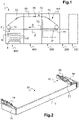
- the Figure 1 represents an example of a shaping machine 1 for the transformation of sheets.
- This shaping machine 1 is conventionally composed of several work stations which are juxtaposed but interdependent one by one to form a unitary assembly.
- each sheet takes place in the transformation station 300, for example between a fixed platen and a lower movable platen of the press 301 for cutting the sheets according to a die corresponding to the developed shape that is wishes to obtain, for example with a view to obtaining a plurality of boxes of a given shape.
- the movable platen successively raises and lowers once during each machine cycle.
- a transport device 70 is also provided to move each sheet individually from the output of the feed table 200 to the sheet reception station 500, passing through the processing station 300 per press.
- the transport device 70 comprises a plurality of transverse bars fitted with grippers, commonly called gripper bars 75, which each in turn pick up a sheet at its front edge, before pulling it successively into the various stations of the stations 300, 400, 500 from machine 1.
- the lateral ends of the gripper bars 75 are each connected respectively to a side chain forming a loop, commonly called chain train 80.
- Chain train 80 Two chain trains 80 are thus arranged laterally on each side of the gripper bars 75.
- the set of gripper bars 75 will start from a stopped position, accelerate, reach a maximum speed, decelerate, then stop, thus describing a cycle corresponding to the movement of a sheet from one workstation to the next workstation.
- the chain trains 80 move and stop periodically so that during each movement, all gripper bars 75 engaged with a sheet have moved from one station to the adjacent downstream work station. Each station performs its work in synchronism with this cycle which is commonly called the machine cycle. Workstations start a new job each time a machine cycle begins.
- shaping machine 1 The number and nature of processing stations in a shaping machine 1 can vary depending on the nature and complexity of the operations to be performed on the sheets. In the context of the invention, the notion of shaping machine 1 thus covers a very large number of embodiments due to the modular structure of these assemblies. Depending on the number, nature and layout of the workstations used, it is indeed possible to obtain a multitude of different processing machines. It is also important to point out that there are other types of workstations than those mentioned, such as embossing stations, upsetting or such as stamping strip loading stations for stamping machine or gilding machine hot ("hot foil stamping" in English) where one realizes between the plates of a press, the deposit on each sheet, of patterns from a film resulting from one or more strips to be stamped. Finally, it is understood that the same shaping machine can very well be equipped with several stations of the same type.
- the converted sheets are stacked in a vertical stack in the reception zone 2, for example on a reception pallet 4 that is movable vertically.
- the shaping machine 1 further comprises at least one storage device 10, arranged in the sheet receiving station 500, for storing the sheets transformed into stacks.
- the shaping machine 1 comprises for example two storage devices 10 oriented opposite a respective face of the stack of sheets, a fixed stop being arranged on the other side of the stack for each storage device 10. There is for example a front storage device 10 and a side storage device 10 per machine 1.
- the storage device 10 comprises a movable storage surface 11 and an actuating device 12 for moving the storage surface 11 between a retracted position and a vertical forward position in a reciprocating movement back and forth for storage sheets in a stack and between the retracted position and a retracted position to free access to the stack of sheet-shaped elements P.
- the storage surface 11 has a flat surface, for example formed in a plate which can be ribbed and/or perforated, such as a grid.
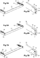
- the storage surface 11 is movable according to a jogging movement, that is to say according to an alternating movement back and forth between the vertical front position ( Fig. 5A , 8A ) and the withdrawal position ( Fig. 6A , 8B ).
- the jogging movement of the storage surface 11 makes it possible to store the sheets after shaping to form a stack. This movement is carried out each time a sheet is received, for example of the order of two or three times per second.
- the storage surface 11 is also movable in the retracted position ( Figure 7A , 8C ) to release access to the stack of P-shaped leaf elements.
- the actuating device 12 comprises cam means configured to move the storage surface 11 upwards in the retracted position, in a high position intended to be located above the top of the stack of sheets ( Figure 8C ).
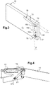
- the cam means comprise at least a first follower roller 14 fixed to the storage surface 11, at one end of the latter ( Figures 3 and 4 ) and at least a first control profile 15, for example formed in a support 16 of the storage device 10 ( Figure 3 ), cooperating with the at least one first follower roller 14 to guide the movements of the storage surface 11.
- the cam means comprising the at least one first follower roller 14 and the at least one first control profile 15 configured to move the storage surface 11 between the retracted position and the retracted position upwards , are the same as those configured to move the storage surface 11 between said retracted position and the vertical front position in the reciprocating movement back and forth for storing the sheets.
- the guiding of the movements of the storage surface 11 by the at least one first follower roller 14 and the at least one first control profile 15, instead of an articulated pivot axis, makes it possible to retract the storage surface 11 to away and above the stack of sheets. It is thus possible to provide, in a simple, robust and economical way, suitable movements of the storage surface 11 by optimizing the functional design of at least a first control profile 15, to provide wide access to the battery in the storage area. reception 2 for easy removal of sheet-like elements P.
- the at least one first control profile 15 is for example straight ( Figure 3 ).
- a same straight line then guides the at least one first follower roller 14 between the three positions, so there are no discontinuities to move the storage surface 11.
- the guiding of the storage surface 11 on the jogging movement represents a small proportion of this straight control profile 15, such as less than 10% of the first control profile 15.
- the straight line of at least one first control profile 15 forms, for example, an angle ⁇ of less than 30° with the horizontal.
- the cam means further comprise at least one second follower roller 17 fixed to the storage surface 11 below the at least one first follower roller 14 and at least one second control profile 18 cooperating with the at least one second follower roller 17 ( Figure 3 ).
- the cam means comprising the at least one second follower roller 17 and the at least one second control profile 18 configured to move the storage surface 11 between the retracted position and the retracted position upwards , are the same as those configured to move the storage surface 11 between said retracted position and the vertical front position in the reciprocating movement back and forth for storing the sheets.
- a first portion 18a of at least a second control profile 18 is curved, such as forming a loop portion, to guide the movement of the storage surface 11 between the retracted position and the vertical front position.
- the curved shape of the second control profile 18 causes the storage surface 11 to move back slightly in the retracted position in addition to its pivoting.
- a second portion 18b of the second control profile 18 is straight to guide the movement of the storage surface 11 between the retracted position and the retracted position.
- the first portion 18a and the second portion 18b are adjacent and continuous to move the storage surface 11 continuously between the three positions.
- the straight line of the second portion 18b of at least one second control profile 18 forms, for example, an angle ⁇ of less than 30° with the vertical.
- the second portion 18b of the second control profile 18 crosses the direction of the first control profile 15, for example at the end of the small proportion of this control profile 15.
- the second control profile 18 may also comprise a third portion 18c, located at the end of the second portion 18b and forming an inclined line with which the second follower roller 17 cooperates in the retracted position ( Figure 3 and 7B ).
- the follower rollers 14, 17 are arranged on the storage surface 11 for example so that their cooperation with the control profiles 15, 18 in the retracted position moves the storage surface 11 in the high position by forming an angle less than 30° with the horizontal.
- the storage surface 11 in the vertical front position, the storage surface 11 is arranged vertically and pushes the sheet away to store it in a stack ( Figure 5A , 8A ).
- the storage surface 11 In the retracted position, the storage surface 11 has pivoted and shifted slightly back from the stack ( Figure 6A , 8B ).
- the storage surface 11 In the retracted position ( Figure 7A , 8C ), the storage surface 11 is raised in a substantially horizontal position and disengaged from the stack.
- the at least one first or second control profile 15, 18 are for example formed in a groove 19, 20.
- the third portion 18c connects for example the two grooves 19, 20.
- the first control profile 15 may comprise two stops, for example formed at the two ends of the groove 19 for the two extreme positions: vertical front and retracted.
- the at least one first control profile 15 and the at least one second control profile 18 can be offset laterally. Provision is made, for example, to form the control profiles 15, 18 in two grooves 19, 20 of different thicknesses, the first control profile 15 being for example formed in the deepest groove 19 ( Figure 3 ). This prevents the at least one first follower roller 14 from cooperating with the at least one second control profile 18, in particular when the first follower roller 14 following the first control profile 15 returns from the retracted position and crosses the second control profile 18 to take the withdrawal position.
- the actuating device 12 may further comprise at least one elastic member 21, such as a traction spring, one end 21a of which is fixed, for example fixed to the support 16, and the other end 21b is fixed to the surface. storage 11 ( Figure 4 ).
- the elastic member 21 makes it possible to ensure that the follower rollers 14, 17 always press on the same side of the groove 19, 20 to cooperate with the respective control profile 15, 18.
- the cam means comprise for example two first follower rollers 14, each fixed to a respective end of the storage surface 11 and two first control profiles 15 cooperating with a respective first follower roller 14.
- the cam means may also comprise two second follower rollers 17 and two second control profiles 18 cooperating with a second follower roller 17 respectively.
- the second follower rollers 17 are each fixed to a respective end of the storage surface 11 below a first follower roller 14.
- the first control profiles 15 and the second control profiles 18 are for example formed in two supports 16 which are arranged laterally, on each side and at each end of the storage surface 11 ( Figure 2 ).
- the drive of the storage surface 11 is for example carried out by means of at least one actuator 22.
- the actuating device 12 comprises for example two actuators 22 each connected to one end of the storage surface 11 ( Figure 2 ).
- the rod of at least one actuator 22 is for example connected to an actuation point located on the back of the first follower roller 14 ( Figure 4 ).
- the at least one actuator 22 comprises a double pneumatic cylinder configured to move the storage surface 11 between the retracted position and the vertical front position over a short stroke and to move the storage surface 11 between the position withdrawal and the retracted position on a long stroke.
- the storage surface 11 is movable according to the reciprocating movement back and forth between the vertical front position ( Figures 5A, 5B , 8A ) and the withdrawal position ( Figures 6A, 6B , 8B ) to arrange the sheets one by one after shaping to form a stack.
- the guiding of the storage surface 11 on the jogging movement is achieved by the reciprocating movement of the first follower rollers 14 against the small portions of the first straight control profiles 15 and of the second follower rollers 17 against the first portions 18a curves of the second control profiles 18.
- the storage surface 11 in the vertical front position, the storage surface 11 is arranged vertically and pushes the sheet to position it in a stack ( Figure 5A, 5B , 8A ). In the retracted position, the storage surface 11 has pivoted and shifted slightly back from the stack ( Figure 6A, 6B , 8B ).
- the first follower rollers 14 continue their movements on the large portions of the first straight control profiles 15 without interruption and the second follower rollers 17 continue their movements on the second straight portions 18b of the second control profiles 18.
- the storage surface 11 is thus moved into the retracted position, for example by forming an angle of less than 30° with the horizontal.
- this retracted position Figure 7A, 7B , 8C
- the storage surface 11 is raised in the high position, substantially horizontal above the stack.
- the storage surface 11 has pivoted and moved back. The retraction of the storage surface 11 away from and above the stack releases a large access area for taking a control sheet.
- the storage surface 11 After taking the sample, the storage surface 11 is controlled in the retracted position.
- the follower rollers 14, 17 then follow the control profiles 15, 18 in the opposite direction.
- the first follower rollers 14 cannot follow the second control profiles 18 when they cross them due to the differences in thickness of the grooves 19, 20.
Description
La présente invention concerne un dispositif de rangement en pile d'éléments en forme de feuilles dans une machine de façonnage. L'invention concerne également une machine de façonnage d'éléments en forme de feuilles comportant au moins un tel dispositif de rangement.The present invention relates to a device for stacking elements in the form of sheets in a shaping machine. The invention also relates to a machine for shaping sheet-like elements comprising at least one such storage device.
Dans l'industrie de fabrication des emballages, les feuilles sont par exemple découpées selon une matrice correspondant à la forme développée que l'on souhaite obtenir, par exemple en vue d'obtenir une pluralité de boîtes d'une forme donnée. Après découpe et éjection des déchets, les points d'attache entre les feuilles de poses sont rompus et les feuilles de poses s'empilent dans une zone de réception où elles sont rangées en piles verticales par un rangeur.In the packaging manufacturing industry, the sheets are for example cut according to a die corresponding to the developed shape that one wishes to obtain, for example with a view to obtaining a plurality of boxes of a given shape. After cutting and ejecting the waste, the points of attachment between the sheets of poses are broken and the sheets of poses pile up in a reception zone where they are arranged in vertical piles by a ranger.
A chaque arrivée d'une nouvelle feuille, une grille de rangement actionnée par des bras articulés pivote légèrement d'une position inclinée dans une position verticale, pour accueillir et ranger la feuille en pile. La grille de rangement reprend ensuite sa position inclinée « en entonnoir » pour la réception d'une nouvelle feuille. Ce mouvement alternatif de va-et-vient de la grille de rangement est également appelé « mouvement de taquage ».Each time a new sheet arrives, a storage grid actuated by articulated arms pivots slightly from an inclined position to a vertical position, to receive and store the sheet in a stack. The storage grid then resumes its inclined "funnel" position to receive a new sheet. This alternating back and forth movement of the storage grid is also called "jogging movement".
Afin de contrôler la qualité de façonnage des feuilles, il s'avère nécessaire de prélever régulièrement des échantillons en cours de production.In order to control the quality of shaping of the sheets, it is necessary to take samples regularly during production.
Pour cela, certains systèmes prévoient de dégager un accès à la pile à l'endroit du rangeur, en repliant les bras qui pivotent la grille de rangement vers l'arrière et vers le bas. Lorsque les bras sont repliés, la grille de rangement a également pivoté à l'horizontale mais reste toujours devant la pile, dans le chemin d'accès à la pile. L'accès à la pile ainsi dégagé au-dessus de la grille est étroit, ce qui ne facilite pas le travail de l'opérateur souhaitant prendre un échantillon.
Un des buts de la présente invention est donc de proposer un dispositif de rangement de feuilles en piles permettant un prélèvement plus aisé des feuilles.One of the aims of the present invention is therefore to propose a device for storing sheets in stacks allowing easier removal of the sheets.
A cet effet, la présente invention a pour objet un dispositif de rangement pour le rangement en pile d'éléments en forme de feuilles dans une machine de façonnage, le dispositif de rangement comportant :
- une surface de rangement mobile, et
- un dispositif d'actionnement pour déplacer la surface de rangement :
- entre une position de retrait et une position avant verticale dans un mouvement alternatif de va-et-vient pour le rangement des feuilles, et
- entre la position de retrait et une position escamotée pour libérer l'accès à la pile d'éléments en forme de feuilles,
- a mobile storage surface, and
- an actuating device for moving the storage surface:
- between a retracted position and a vertical forward position in an alternating back and forth motion for storing the sheets, and
- between the retracted position and a retracted position to free access to the stack of sheet-like elements,
L'accès à la pile de feuilles est ainsi libéré sur toute sa hauteur.Access to the stack of sheets is thus released over its entire height.
Pour cela, les moyens de came comportent au moins un premier galet suiveur fixé à la surface de rangement et au moins un premier profil de commande coopérant avec le au moins un premier galet suiveur pour guider ledit déplacement de la surface de rangement.For this, the cam means comprise at least one first follower roller fixed to the storage surface and at least one first control profile cooperating with the at least one first follower roller to guide said movement of the storage surface.
Selon un exemple de réalisation, les moyens de came, comprenant le au moins un premier galet suiveur et le au moins un premier profil de commande configurés pour déplacer la surface de rangement entre la position de retrait et la position escamotée vers le haut, sont les mêmes que ceux configurés pour déplacer la surface de rangement entre ladite position de retrait et la position avant verticale dans le mouvement alternatif de va-et-vient pour le rangement des feuilles.According to an exemplary embodiment, the cam means, comprising the at least one first follower roller and the at least one first control profile configured to move the storage surface between the retracted position and the retracted position upwards, are the same as those configured to move the storage surface between said retracted position and the vertical forward position in the back-and-forth reciprocating motion for sheet storage.
Le guidage des déplacements de la surface de rangement par le au moins un premier galet suiveur et le au moins un premier profil de commande, au lieu d'un axe de pivotement articulé, permet d'escamoter la surface de rangement au-dessus de la pile de feuilles. Il est ainsi possible de prévoir de façon simple, robuste et économique, des mouvements adaptés de la surface de rangement en optimisant le design fonctionnel du au moins un premier profil de commande, pour dégager un large accès à la pile dans la zone de réception pour le prélèvement aisé d'éléments en forme de feuilles.The guiding of the movements of the storage surface by the at least one first follower roller and the at least one first control profile, instead of an articulated pivot axis, makes it possible to retract the storage surface above the stack of sheets. It is thus possible to provide, in a simple, robust and economical way, suitable movements of the storage surface by optimizing the functional design of at least a first control profile, to provide wide access to the battery in the reception area for the easy removal of leaf-shaped elements.
Selon un exemple de réalisation, le au moins un premier profil de commande est droit.According to an exemplary embodiment, the at least one first control profile is straight.
La droite du au moins un premier profil de commande forme par exemple un angle inférieur à 30° avec l'horizontale.The straight line of the at least one first control profile forms, for example, an angle of less than 30° with the horizontal.
Les moyens de came comportent au moins un deuxième galet suiveur fixé à la surface de rangement au-dessous du au moins un premier galet suiveur et au moins un deuxième profil de commande coopérant avec le au moins un deuxième galet suiveur.The cam means comprise at least one second follower roller fixed to the storage surface below the at least one first follower roller and at least one second control profile cooperating with the at least one second follower roller.
Une première portion du au moins un deuxième profil de commande est courbe pour guider le déplacement de la surface de rangement entre la position de retrait et la position avant verticale et une deuxième portion du deuxième profil de commande est droite pour guider le déplacement de la surface de rangement entre la position de retrait et la position escamotée.A first portion of the at least one second control profile is curved to guide the movement of the storage surface between the retracted position and the vertical front position and a second portion of the second control profile is straight to guide the movement of the surface storage between the retracted position and the retracted position.
Selon un exemple de réalisation, les moyens de came, comprenant le au moins un deuxième galet suiveur et le au moins un deuxième profil de commande configurés pour déplacer la surface de rangement entre la position de retrait et la position escamotée vers le haut, sont les mêmes que ceux configurés pour déplacer la surface de rangement entre ladite position de retrait et la position avant verticale dans le mouvement alternatif de va-et-vient pour le rangement des feuilles.According to an exemplary embodiment, the cam means, comprising the at least one second follower roller and the at least one second control profile configured to moving the storage surface between the retracted position and the retracted upward position are the same as those configured to move the storage surface between said retracted position and the vertical forward position in the reciprocating back and forth motion for storing sheets.
La droite de la deuxième portion du au moins un deuxième profil de commande forme par exemple un angle inférieur à 30° avec la verticale.The straight line of the second portion of the at least one second control profile forms, for example, an angle of less than 30° with the vertical.
La deuxième portion du deuxième profil de commande croise par exemple la direction du premier profil de commande.The second portion of the second command profile crosses for example the direction of the first command profile.
Les galets suiveurs sont agencés sur la surface de rangement par exemple pour que leur coopération avec les profils de commande dans la position escamotée déplace la surface de rangement en position haute en formant un angle inférieur à 30° avec l'horizontale.The cam followers are arranged on the storage surface, for example so that their cooperation with the control profiles in the retracted position moves the storage surface into the high position by forming an angle of less than 30° with the horizontal.
Le au moins un premier profil de commande et le au moins un deuxième profil de commande peuvent être décalés latéralement pour empêcher le au moins un premier galet suiveur de coopérer avec le au moins un deuxième profil de commande, notamment lorsque le premier galet suiveur suivant le premier profil de commande revient de la position escamotée et croise le deuxième profil de commande.The at least one first control profile and the at least one second control profile can be offset laterally to prevent the at least one first follower roller from cooperating with the at least one second control profile, in particular when the first follower roller following the first control profile returns from the retracted position and crosses the second control profile.
Le au moins un premier ou deuxième profil de commande est par exemple formé dans une rainure.The at least one first or second control profile is for example formed in a groove.
Le dispositif d'actionnement peut comporter au moins un organe élastique ayant une extrémité fixe et une extrémité fixée à la surface de rangement pour assurer un contact du au moins un premier galet suiveur sur le au moins un premier profil de commande et, le cas échéant, du au moins un deuxième galet suiveur sur le au moins un deuxième profil de commande. L'organe élastique permet de s'assurer que les galets suiveurs appuient sur un profil de commande respectif.The actuating device may comprise at least one elastic member having a fixed end and an end fixed to the storage surface to ensure contact of the at least one first follower roller on the at least one first control profile and, if necessary , of the at least one second follower roller on the at least one second control profile. The elastic member makes it possible to ensure that the follower rollers bear on a respective control profile.
Selon un exemple de réalisation, les moyens de came comportent deux premiers galets suiveurs, chacun fixé à une extrémité respective de la surface de rangement et deux premiers profils de commande coopérant avec un premier galet suiveur respectif.According to an exemplary embodiment, the cam means comprise two first follower rollers, each fixed to a respective end of the storage surface and two first control profiles cooperating with a respective first follower roller.
Selon un exemple de réalisation, les moyens de came comportent deux deuxièmes galets suiveurs, chacun fixé à une extrémité respective de la surface de rangement au-dessous d'un premier galet suiveur et deux deuxièmes profils de commande coopérant avec un deuxième galet suiveur respectif.According to an exemplary embodiment, the cam means comprise two second follower rollers, each fixed to a respective end of the storage surface below a first follower roller and two second control profiles cooperating with a respective second follower roller.
Le dispositif d'actionnement comporte par exemple au moins un actionneur pour entraîner le déplacement de la surface de rangement.The actuating device comprises for example at least one actuator to drive the movement of the storage surface.
Le au moins un actionneur comporte par exemple un double vérin pneumatique configuré pour déplacer la surface de rangement entre la position de retrait et la position avant verticale sur une petite course et pour déplacer la surface de rangement entre la position de retrait et la position escamotée sur une grande course.The at least one actuator comprises for example a double pneumatic cylinder configured to move the storage surface between the retracted position and the vertical front position over a short stroke and to move the storage surface between the retracted position and the retracted position on a great race.
L'invention a aussi pour objet une machine de façonnage d'éléments en forme de feuilles, caractérisée en ce qu'elle comporte au moins un dispositif de rangement en pile d'éléments en forme de feuilles tel que décrit précédemment.The invention also relates to a machine for shaping sheet-shaped elements, characterized in that it comprises at least one storage device in a stack of sheet-shaped elements as described above.
D'autres avantages et caractéristiques apparaîtront à la lecture de la description de l'invention, ainsi que sur les figures annexées qui représentent un exemple de réalisation non limitatif de l'invention et sur lesquelles :
- La
Figure 1 illustre de façon très schématique un exemple de machine de façonnage d'éléments en forme de feuilles. - La
Figure 2 montre une vue en perspective d'un dispositif de rangement de la machine de façonnage de laFigure 1 . - La
Figure 3 montre une vue en perspective d'éléments d'un dispositif d'actionnement du dispositif de rangement de laFigure 2 . - La
Figure 4 montre une vue partielle en perspective d'un détail du dispositif de rangement de laFigure 2 . - La
Figure 5A montre une vue en perspective d'éléments du dispositif de rangement de laFigure 2 avec la surface de rangement en position avant verticale. - La
Figure 5B montre les éléments du dispositif d'actionnement de laFigure 3 en position avant verticale. - La
Figure 6A montre une vue analogue à laFigure 5A avec la surface de rangement en position de retrait. - La
Figure 6B montre une vue analogue à laFigure 5B en position de retrait. - La
Figure 7A montre une vue analogue à laFigure 5A avec la surface de rangement en position escamotée. - La
Figure 7B montre une vue analogue à laFigure 5B en position escamotée. - La
Figure 8A montre une vue de côté d'une pile d'éléments en forme de feuilles et du dispositif d'actionnement de laFigure 2 avec la surface de rangement en position avant verticale. - La
Figure 8B montre une vue analogue à laFigure 8A avec la surface de rangement en position de retrait. - La
Figure 8C montre une vue analogue à laFigure 8A avec la surface de rangement en position escamotée.
- The
Figure 1 very schematically illustrates an example of a machine for forming sheet-shaped elements. - The
Figure 2 shows a perspective view of a storage device of the molding machineFigure 1 . - The
Figure 3 shows a perspective view of elements of an actuation device of the storage device of theFigure 2 . - The
Figure 4 shows a partial perspective view of a detail of the storage device of theFigure 2 . - The
Figure 5A shows a perspective view of elements of the storage device of theFigure 2 with the storage surface in the vertical front position. - The
Figure 5B shows the elements of the actuating device of theFigure 3 in the upright forward position. - The
Figure 6A shows a view similar to theFigure 5A with the storage surface in the retracted position. - The
Figure 6B shows a view similar to theFigure 5B in the withdrawn position. - The
Figure 7A shows a view similar to theFigure 5A with the storage surface in the retracted position. - The
Figure 7B shows a view similar to theFigure 5B in the retracted position. - The
Figure 8A shows a side view of a stack of sheet-like elements and the actuation device of theFigure 2 with the storage surface in the vertical front position. - The
Figure 8B shows a view similar to theFigure 8A with the storage surface in the retracted position. - The
Figure 8C shows a view similar to theFigure 8A with the storage surface in the retracted position.
Sur ces figures, les éléments identiques portent les mêmes numéros de référence. Les réalisations suivantes sont des exemples. Bien que la description se réfère à un ou plusieurs modes de réalisation, ceci ne signifie pas nécessairement que chaque référence concerne le même mode de réalisation, ou que les caractéristiques s'appliquent seulement à un seul mode de réalisation. De simples caractéristiques de différents modes de réalisation peuvent également être combinées ou interchangées pour fournir d'autres réalisations.In these figures, identical elements bear the same reference numbers. The following achievements are examples. Although the description refers to one or more embodiments, this does not necessarily mean that each reference is to the same embodiment, or that the features apply only to a single embodiment. Simple features of different embodiments can also be combined or interchanged to provide other embodiments.
On définit les termes amont et aval en référence à la direction longitudinale de déplacement des feuilles D (
Les termes « éléments en forme de feuilles » et « feuilles » seront considérés comme équivalents, et concerneront aussi bien des éléments composés de carton ondulé que de carton plat, de papier ou de toute autre matière utilisée couramment dans l'industrie de l'emballage. Il est entendu que dans l'ensemble de ce texte, les termes « feuille » ou « élément en feuilles » ou « élément en forme de feuilles » désignent de façon très générale tout support d'impression en forme de feuilles tel que, par exemple, des feuilles de carton, de papier, de matière plastique, etc..The terms "sheet-shaped elements" and "sheets" will be considered equivalent, and will concern elements made of corrugated cardboard as well as flat cardboard, paper or any other material commonly used in the packaging industry. . It is understood that throughout this text, the terms "sheet" or "element in sheets" or "element in the form of sheets" refer very generally to any printing medium in the form of sheets such as, for example , sheets of cardboard, paper, plastic, etc.
Les termes « dessus », « dessous », « haut », « bas » « horizontale » et « verticale » sont définis en référence à la disposition des éléments dans une machine de façonnage posée au sol.The terms "above", "below", "top", "bottom", "horizontal" and "vertical" are defined with reference to the arrangement of the elements in a shaping machine placed on the ground.
La
L'opération de transformation de chaque feuille s'opère dans la station de transformation 300, par exemple entre une platine fixe et une platine mobile inférieure de la presse 301 pour la découpe des feuilles selon une matrice correspondant à la forme développée que l'on souhaite obtenir, par exemple en vue d'obtenir une pluralité de boîtes d'une forme donnée. La platine mobile s'élève et s'abaisse successivement une fois au cours de chaque cycle machine.The transformation operation of each sheet takes place in the
Un dispositif de transport 70 est par ailleurs prévu pour déplacer individuellement chaque feuille depuis la sortie de la table de marge 200 jusqu'à la station de réception des feuilles 500, en passant par la station de transformation 300 par presse.A
Le dispositif de transport 70 comporte une pluralité de barres transversales munies de pinces, communément appelées barres de pinces 75 qui viennent chacune à leur tour saisir une feuille au niveau de son bord frontal, avant de la tirer successivement dans les différents postes des stations 300, 400, 500 de la machine 1.The
Les extrémités latérales des barres de pinces 75 sont chacune reliées respectivement à une chaîne latérale formant une boucle, communément appelée train de chaînes 80. Deux trains de chaînes 80 sont ainsi disposés latéralement de chaque côté des barres de pinces 75.The lateral ends of the gripper bars 75 are each connected respectively to a side chain forming a loop, commonly called
Grâce à un mouvement transmis aux trains de chaînes 80, l'ensemble des barres de pinces 75 va partir d'une position arrêtée, accélérer, atteindre une vitesse maximale, décélérer, puis s'arrêter, en décrivant ainsi un cycle correspondant au déplacement d'une feuille d'une station de travail à la station de travail suivant. Les trains de chaînes 80 se déplacent et s'arrêtent périodiquement de sorte que, durant chaque déplacement, toutes les barres de pinces 75 en prise avec une feuille sont passées d'une station à la station de travail aval adjacente. Chaque station effectue son travail en synchronisme avec ce cycle que l'on appelle communément cycle machine. Les stations de travail démarrent un nouveau travail à chaque début de cycle machine.Thanks to a movement transmitted to the chain trains 80, the set of gripper bars 75 will start from a stopped position, accelerate, reach a maximum speed, decelerate, then stop, thus describing a cycle corresponding to the movement of a sheet from one workstation to the next workstation. The chain trains 80 move and stop periodically so that during each movement, all gripper bars 75 engaged with a sheet have moved from one station to the adjacent downstream work station. Each station performs its work in synchronism with this cycle which is commonly called the machine cycle. Workstations start a new job each time a machine cycle begins.
Le nombre et la nature des stations de traitement dans une machine de façonnage 1 peuvent varier en fonction de la nature et de la complexité des opérations à effectuer sur les feuilles. Dans le cadre de l'invention, la notion de machine de façonnage 1 couvre ainsi un très grand nombre de réalisations du fait de la structure modulaire de ces ensembles. Suivant le nombre, la nature et l'agencement des stations de travail utilisées, il est en effet possible d'obtenir une multitude de machines de traitement différentes. Il est également important de souligner qu'il existe d'autres types de stations de travail que celles évoquées, telles que des stations de gaufrage, refoulage ou telles que des stations de chargement de bandes à estamper pour machine d'estampage ou machine de dorure à chaud (« hot foil stamping » en anglais) où on réalise entre les platines d'une presse, la dépose sur chaque feuille, de motifs à partir d'un film issu d'une ou de plusieurs bandes à estamper. Enfin, il est entendu qu'une même machine de façonnage peut très bien être équipée de plusieurs stations d'un même type.The number and nature of processing stations in a shaping
Dans la station de réception des feuilles 500, les feuilles transformées s'empilent en pile verticale dans la zone de réception 2, par exemple sur une palette de réception 4 mobile verticalement.In the
La machine de façonnage 1 comporte en outre au moins un dispositif de rangement 10, agencé dans la station de réception des feuilles 500, pour le rangement des feuilles transformées en piles.The shaping
La machine de façonnage 1 comporte par exemple deux dispositifs de rangement 10 orientés en regard d'une face respective de la pile de feuilles, une butée fixe étant disposée de l'autre côté de la pile pour chaque dispositif de rangement 10. Il y a par exemple un dispositif de rangement 10 frontal et un dispositif de rangement 10 latéral par machine 1.The shaping
Comme on peut le voir sur la
La surface de rangement 11 présente une surface plane, par exemple formée dans une plaque pouvant être nervurée et/ou ajourée, telle qu'une grille.The
La surface de rangement 11 est mobile selon un mouvement de taquage, c'est à dire selon un mouvement alternatif de va-et-vient entre la position avant verticale (
La surface de rangement 11 est également mobile dans la position escamotée (
Le dispositif d'actionnement 12 comporte des moyens de came configurés pour déplacer la surface de rangement 11 vers le haut en position escamotée, dans une position haute destinée à être située au-dessus du sommet de la pile de feuilles (
L'accès à la pile de feuilles est ainsi libéré sur toute sa hauteur.Access to the stack of sheets is thus released over its entire height.
Pour cela par exemple, les moyens de came comportent au moins un premier galet suiveur 14 fixé à la surface de rangement 11, à une extrémité de celle-ci (
Selon un exemple de réalisation, les moyens de came, comprenant le au moins un premier galet suiveur 14 et le au moins un premier profil de commande 15 configurés pour déplacer la surface de rangement 11 entre la position de retrait et la position escamotée vers le haut, sont les mêmes que ceux configurés pour déplacer la surface de rangement 11 entre ladite position de retrait et la position avant verticale dans le mouvement alternatif de va-et-vient pour le rangement des feuilles.According to an exemplary embodiment, the cam means, comprising the at least one
Le guidage des déplacements de la surface de rangement 11 par le au moins un premier galet suiveur 14 et le au moins un premier profil de commande 15, au lieu d'un axe de pivotement articulé, permet d'escamoter la surface de rangement 11 à l'écart et au-dessus de la pile de feuilles. Il est ainsi possible de prévoir de façon simple, robuste et économique, des mouvements adaptés de la surface de rangement 11 en optimisant le design fonctionnel du au moins un premier profil de commande 15, pour dégager un large accès à la pile dans la zone de réception 2 pour le prélèvement aisé d'éléments en forme de feuilles P.The guiding of the movements of the
Le au moins un premier profil de commande 15 est par exemple droit (
Les moyens de came comportent en outre au moins un deuxième galet suiveur 17 fixé à la surface de rangement 11 au-dessous du au moins un premier galet suiveur 14 et au moins un deuxième profil de commande 18 coopérant avec le au moins un deuxième galet suiveur 17 (
Selon un exemple de réalisation, les moyens de came, comprenant le au moins un deuxième galet suiveur 17 et le au moins un deuxième profil de commande 18 configurés pour déplacer la surface de rangement 11 entre la position de retrait et la position escamotée vers le haut, sont les mêmes que ceux configurés pour déplacer la surface de rangement 11 entre ladite position de retrait et la position avant verticale dans le mouvement alternatif de va-et-vient pour le rangement des feuilles.According to an exemplary embodiment, the cam means, comprising the at least one
Une première portion 18a du au moins un deuxième profil de commande 18 est courbe, tel que formant une portion de boucle, pour guider le déplacement de la surface de rangement 11 entre la position de retrait et la position avant verticale. La forme courbe du deuxième profil de commande 18 entraîne un léger recul de la surface de rangement 11 en position de retrait en plus de son pivotement.A
Une deuxième portion 18b du deuxième profil de commande 18 est droite pour guider le déplacement de la surface de rangement 11 entre la position de retrait et la position escamotée. La première portion 18a et la deuxième portion 18b sont adjacentes et continues pour déplacer la surface de rangement 11 de façon continue entre les trois positions. La droite de la deuxième portion 18b du au moins un deuxième profil de commande 18 forme par exemple un angle β inférieur à 30° avec la verticale.A
La deuxième portion 18b du deuxième profil de commande 18 croise la direction du premier profil de commande 15, par exemple à l'extrémité de la petite proportion de ce profil de commande 15.The
Le deuxième profil de commande 18 peut en outre comporter une troisième portion 18c, située à l'extrémité de la deuxième portion 18b et formant une droite inclinée avec laquelle le deuxième galet suiveur 17 coopère en position escamotée (
Les galets suiveurs 14, 17 sont agencés sur la surface de rangement 11 par exemple pour que leur coopération avec les profils de commande 15, 18 dans la position escamotée déplace la surface de rangement 11 en position haute en formant un angle inférieur à 30° avec l'horizontale.The
Ainsi, dans la position avant verticale, la surface de rangement 11 est disposée verticalement et repousse la feuille pour la ranger en pile (
Le au moins un premier ou deuxième profil de commande 15, 18 sont par exemple formés dans une rainure 19, 20. La troisième portion 18c relie par exemple les deux rainures 19, 20.The at least one first or
Le premier profil de commande 15 peut comporter deux butées, par exemple formées aux deux extrémités de la rainure 19 pour les deux positions extrêmes : avant verticale et escamotée.The
Le au moins un premier profil de commande 15 et le au moins un deuxième profil de commande 18 peuvent être décalés latéralement. On prévoit par exemple de former les profils de commande 15, 18 dans deux rainures 19, 20 d'épaisseurs différentes, le premier profil de commande 15 étant par exemple formé dans la rainure 19 la plus profonde (
Le dispositif d'actionnement 12 peut en outre comporter au moins un organe élastique 21, tel qu'un ressort en traction, dont une extrémité 21a est fixe, par exemple fixée au support 16, et l'autre extrémité 21b est fixée à la surface de rangement 11 (
Les moyens de came comportent par exemple deux premiers galets suiveurs 14, chacun fixé à une extrémité respective de la surface de rangement 11 et deux premiers profils de commande 15 coopérant avec un premier galet suiveur 14 respectif. En outre, les moyens de came peuvent également comporter deux deuxièmes galets suiveurs 17 et deux deuxièmes profils de commande 18 coopérant avec un deuxième galet suiveur 17 respectif. Les deuxièmes galets suiveurs 17 sont chacun fixé à une extrémité respective de la surface de rangement 11 au-dessous d'un premier galet suiveur 14.The cam means comprise for example two
Les premiers profils de commande 15 et les deuxièmes profils de commande 18 sont par exemple ménagés dans deux supports 16 qui sont agencés latéralement, de chaque côté et à chaque extrémité de la surface de rangement 11 (
L'entrainement de la surface de rangement 11 est par exemple réalisé au moyen d'au moins un actionneur 22.The drive of the
Le dispositif d'actionnement 12 comporte par exemple deux actionneurs 22 chacun relié à une extrémité de la surface de rangement 11 (
La tige du au moins un actionneur 22 est par exemple reliée à un point d'actionnement situé au dos du premier galet suiveur 14 (
Selon un exemple de réalisation, le au moins un actionneur 22 comporte un double vérin pneumatique configuré pour déplacer la surface de rangement 11 entre la position de retrait et la position avant verticale sur une petite course et pour déplacer la surface de rangement 11 entre la position de retrait et la position escamotée sur une grande course.According to an exemplary embodiment, the at least one
On va maintenant décrire un exemple de fonctionnement d'un dispositif de rangement 10 dans une zone de réception 2 d'une station de réception des feuilles 500.We will now describe an example of the operation of a
En production, la surface de rangement 11 est mobile selon le mouvement alternatif de va-et-vient entre la position avant verticale (
Le guidage de la surface de rangement 11 sur le mouvement de taquage est réalisé par le mouvement de va-et-vient des premiers galets suiveurs 14 contre les petites portions des premiers profils de commande 15 droits et des seconds galets suiveurs 17 contre les premières portions 18a courbes des deuxièmes profils de commande 18.The guiding of the
Ainsi, dans la position avant verticale, la surface de rangement 11 est disposée verticalement et pousse la feuille pour la positionner en pile (
Lorsque l'utilisateur souhaite prélever une feuille transformée, il commande les actionneurs 22 sur la grande course pour basculer la surface de rangement 11 dans la position escamotée (
Les premiers galets suiveurs 14 poursuivent leurs déplacements sur les grandes portions des premiers profils de commande 15 droits sans discontinuité et les deuxièmes galets suiveurs 17 poursuivent leurs déplacements sur les deuxièmes portions 18b droites des deuxièmes profils de commande 18. La surface de rangement 11 est ainsi déplacée dans la position escamotée, par exemple en formant un angle inférieur à 30° avec l'horizontale. Dans cette position escamotée (
Après prélèvement de l'échantillon, la surface de rangement 11 est commandée en position de retrait. Les galets suiveurs 14, 17 suivent alors les profils de commande 15, 18 en sens inverse. Les premiers galets suiveurs 14 ne peuvent pas suivre les deuxièmes profils de commande 18 lorsqu'ils les croisent du fait des différences d'épaisseurs des rainures 19, 20.After taking the sample, the
Claims (15)
- Storage device (10) for storing sheet-type elements (P) in piles in a shaping machine (1), the storage device (10) comprising:- a movable storage surface (11) and- an actuating device (12) for moving the storage surface (11):the actuating device (12) comprising cam means for moving the storage surface (11) upwards into the stowed position, in an upper position intended to be located above the top of the pile of sheets, the cam means comprising at least one first cam follower (14) fixed to the storage surface (11) and at least one first control profile (15) cooperating with the at least one first cam follower (14) to guide said movement of the storage surface (11), characterised in that the cam means comprise at least one second cam follower (17) fixed to the storage surface (11) below the at least one first cam follower (14) and at least one second control profile (18) cooperating with the at least one second cam follower (17), a first portion (18a) of the at least one second control profile (18) being curved to guide the movement of the storage surface (11) between the retracted position and the vertical front position and a second portion (18b) of the second control profile (18) being straight to guide the movement of the storage surface (11) between the retracted position and the stowed position.- between a retracted position and a vertical front position in an alternating back-and-forth movement for storing the sheets in a pile, and- between the retracted position and a stowed position for freeing the access to the pile of sheet-type elements (P),
- Storage device (10) according to the preceding claim, characterised in that the cam means configured to move the storage surface between the retracted position and the stowed position upwards are the same as those configured to move the storage surface between said retracted position and the vertical front position for storing the sheets.
- Storage device (10) according to one of the preceding claims, characterised in that the at least one first control profile (15) is straight.
- Storage device (10) according to the preceding claim, characterised in that the straight line of the at least one first control profile (15) forms an angle (α) less than 30° with the horizontal.
- Storage device (10) according to one of the preceding claims, characterised in that the straight line of the second portion (18b) of the at least one second control profile (18) forms and angle (β) less than 30° with the vertical.
- Storage device (10) according to one of the preceding claims, characterised in that the second portion (18b) of the second control profile (18) crosses the direction of the first control profile (15).
- Storage device (10) according to one of the preceding claims, characterised in that the cam followers (14, 17) are arranged on the storage surface (11) so that their cooperation with the control profiles (15, 18) in the stowed position moves the storage surface (11) in the upper position by forming an angle less than 30° with the horizontal.
- Storage device (10) according to one of the preceding claims, characterised in that the at least one first control profile (15) and the at least one second control profile (18) are laterally offset in order to prevent the at least one first cam follower (14) from cooperating with the at least one second control profile (18).
- Storage device (10) according to one of the preceding claims, characterised in that at least one first or second control profile (15, 18) is formed in a groove (19, 20).
- Storage device (10) according to one of the preceding claims, characterised in that the actuating device (12) comprises at least one elastic member (21) having a fixed end (21a) and an end fixed to the storage surface (11) in order to ensure contact of the at least one first cam follower (14) on the at least one first control profile (15).
- Storage device (10) according to one of the preceding claims, characterised in that the cam means comprise:- two first cam followers (14), each fixed to a respective end of the storage surface (11),- two first control profiles (15) cooperating with a first respective cam follower (14).
- Storage device (10) according to the preceding claim, characterised in that the cam means comprise:- two second cam followers (17) each fixed to a respective end of the storage surface (11) below a first cam follower (14),- two second control profiles (18) cooperating with a second respective cam follower (17).
- Storage device (10) according to one of the preceding claims, characterised in that the actuating device (12) comprises at least one actuator (22) for driving the movement of the storage surface (11).
- Storage device (10) according to the preceding claim, characterised in that the at least one actuator (22) comprises a double pneumatic cylinder configured to move the storage surface (11) between the retracted position and the vertical front position over a short course and to move the storage surface (11) between the retracted position and the stowed position over a long course.
- Machine for shaping (1) sheet-type elements, characterised in that it comprises at least one storage device (10) for sheet-type elements (P) in piles according to one of the preceding claims.
Applications Claiming Priority (2)
| Application Number | Priority Date | Filing Date | Title |
|---|---|---|---|
| EP18020254 | 2018-06-14 | ||
| PCT/EP2019/025125 WO2019238264A1 (en) | 2018-06-14 | 2019-04-25 | Storage device and machine for shaping sheet-type elements |
Publications (2)
| Publication Number | Publication Date |
|---|---|
| EP3807201A1 EP3807201A1 (en) | 2021-04-21 |
| EP3807201B1 true EP3807201B1 (en) | 2022-03-30 |
Family
ID=62705357
Family Applications (1)
| Application Number | Title | Priority Date | Filing Date |
|---|---|---|---|
| EP19720369.8A Active EP3807201B1 (en) | 2018-06-14 | 2019-04-25 | Organising system and machine for treating sheet-shaped elements |
Country Status (9)
| Country | Link |
|---|---|
| US (1) | US11795025B2 (en) |
| EP (1) | EP3807201B1 (en) |
| JP (1) | JP7080998B2 (en) |
| KR (1) | KR102276271B1 (en) |
| CN (1) | CN112313164B (en) |
| BR (1) | BR112020023377A2 (en) |
| ES (1) | ES2912407T3 (en) |
| TW (1) | TWI722416B (en) |
| WO (1) | WO2019238264A1 (en) |
Family Cites Families (20)
| Publication number | Priority date | Publication date | Assignee | Title |
|---|---|---|---|---|
| JPS59108759U (en) | 1983-01-14 | 1984-07-21 | 三菱重工業株式会社 | delivery equipment |
| JPS61127564A (en) | 1984-11-28 | 1986-06-14 | Hitachi Ltd | Device for stacking sheets |
| DE3618622A1 (en) * | 1986-06-03 | 1987-12-10 | Roland Man Druckmasch | BACK EDGE STOP AT BOW BOOMS ON BOW-PROCESSING MACHINES |
| US5374051A (en) | 1993-04-21 | 1994-12-20 | Xerox Corporation | Relief device for offset stacker tamping mechanism |
| DE4442385C1 (en) * | 1994-11-29 | 1996-01-04 | Heidelberger Druckmasch Ag | Device for forming stacks of sheets |
| US5544583A (en) * | 1995-06-08 | 1996-08-13 | A.B. Dick Company | Delivery interrupt mechanism for a printing machine |
| US6510792B1 (en) * | 1996-09-26 | 2003-01-28 | Heidelberger Druckmaschinen Aktiengesellschaft | Device for forming a sheet pile for a sheet fed rotary printing press |
| CH695266A5 (en) * | 2002-04-03 | 2006-02-28 | Bobst Sa | Device for return of material cell sheet. |
| JP4311295B2 (en) * | 2004-07-22 | 2009-08-12 | 船井電機株式会社 | Paper tray support structure |
| DE102008008510B4 (en) * | 2007-03-07 | 2019-06-06 | Heidelberger Druckmaschinen Ag | Method and device for sample sheet removal |
| DE102009046987B4 (en) * | 2009-11-23 | 2023-06-01 | Koenig & Bauer Ag | Delivery of a sheet-processing machine with a delivery stack receiving a sheet and a method for changing the stack |
| JP5787612B2 (en) * | 2010-06-22 | 2015-09-30 | キヤノン株式会社 | Image forming apparatus |
| JP5583159B2 (en) * | 2012-03-01 | 2014-09-03 | キヤノン株式会社 | Image forming apparatus |
| JP6229425B2 (en) * | 2013-10-15 | 2017-11-15 | 富士ゼロックス株式会社 | Paper processing apparatus, image forming system, and program |
| JP6122826B2 (en) | 2014-11-14 | 2017-04-26 | 株式会社小矢部精機 | Sheet material separation assist device |
| JP6558955B2 (en) * | 2015-05-28 | 2019-08-14 | キヤノン株式会社 | Sheet stacking apparatus and image forming apparatus |
| EP3271275B1 (en) * | 2015-06-29 | 2018-10-17 | Koenig & Bauer AG | Method for operating a stacking device and stacking device for a sheet processing machine |
| EP3147244B1 (en) * | 2015-09-25 | 2018-02-21 | Guangdong Fosber Intelligent Equipment Co., Ltd. | Sheet stacker and method for forming stacks of staggered bundles |
| JP6410324B2 (en) * | 2016-02-15 | 2018-10-24 | キヤノンファインテックニスカ株式会社 | Sheet stacking device |
| JP2019127379A (en) | 2018-01-26 | 2019-08-01 | コニカミノルタ株式会社 | Paper feeder and image forming device |
-
2019
- 2019-04-18 TW TW108113593A patent/TWI722416B/en active
- 2019-04-25 ES ES19720369T patent/ES2912407T3/en active Active
- 2019-04-25 KR KR1020207036677A patent/KR102276271B1/en active IP Right Grant
- 2019-04-25 BR BR112020023377-3A patent/BR112020023377A2/en unknown
- 2019-04-25 EP EP19720369.8A patent/EP3807201B1/en active Active
- 2019-04-25 JP JP2020568957A patent/JP7080998B2/en active Active
- 2019-04-25 US US15/733,829 patent/US11795025B2/en active Active
- 2019-04-25 CN CN201980039928.1A patent/CN112313164B/en active Active
- 2019-04-25 WO PCT/EP2019/025125 patent/WO2019238264A1/en active Application Filing
Also Published As
| Publication number | Publication date |
|---|---|
| CN112313164A (en) | 2021-02-02 |
| EP3807201A1 (en) | 2021-04-21 |
| TW202017835A (en) | 2020-05-16 |
| KR102276271B1 (en) | 2021-07-13 |
| WO2019238264A1 (en) | 2019-12-19 |
| ES2912407T3 (en) | 2022-05-25 |
| JP2021526494A (en) | 2021-10-07 |
| KR20210003289A (en) | 2021-01-11 |
| CN112313164B (en) | 2023-06-23 |
| BR112020023377A2 (en) | 2021-02-09 |
| TWI722416B (en) | 2021-03-21 |
| JP7080998B2 (en) | 2022-06-06 |
| US20210214179A1 (en) | 2021-07-15 |
| US11795025B2 (en) | 2023-10-24 |
Similar Documents
| Publication | Publication Date | Title |
|---|---|---|
| EP2616243B1 (en) | Device for printing by stamping | |
| EP2914523B1 (en) | Device for holding a flat sheet-like element circulating in a treatment machine | |
| EP2512807B1 (en) | Hot-stamping printing device | |
| EP3003703B1 (en) | Processing unit of a continuous-strip support and machine for producing packaging provided therewith | |
| FR2484978A1 (en) | SYSTEM FOR CONTINUOUS DISCHARGE AND RECEPTION OF SHEETS | |
| FR2499040A1 (en) | APPARATUS FOR RECEIVING AND TRANSFERRING SHEET MATERIAL | |
| EP3612483B1 (en) | Device and method for checking blank samples, discharge station, and machine for treating elements in sheet form | |
| EP2616242B1 (en) | Device for guiding strips for a stamping machine | |
| EP3612484B1 (en) | Device for recovering blanking samples, discharge station and machine for treating elements in sheet form | |
| EP2704973B1 (en) | Device for stacking sheets of paper or similar | |
| EP0244308B1 (en) | Machine for receiving and piling cut sheets | |
| EP3414199B1 (en) | Mobile carriage, device for gripping insert sheets, station for receiving installations and machine for treating sheet-shaped elements | |
| EP0741096B1 (en) | Transporting device for metallized webs | |
| EP3807201B1 (en) | Organising system and machine for treating sheet-shaped elements | |
| EP3414198B1 (en) | Device for gripping insert sheets, loading device, station for receiving installations and machine for treating sheet-shaped elements | |
| EP3426449B1 (en) | Ejector and machine for treating sheet-shaped elements | |
| EP3612482B1 (en) | Device and method for ejecting blanking samples, discharge station and machine for treating elements in sheet form | |
| WO2017178437A1 (en) | Gripping member, gripper bar and machine for processing elements in sheet form | |
| FR2975980A1 (en) | Stacking device for vertical stacking of documents, has lower section with top face partially sealable using stops, where stops and bottom face of section are movable upwardly and downwardly within stacking well to press stack of documents | |
| FR2764276A1 (en) | METHOD AND INSTALLATION FOR THE AUTOMATIC PREPARATION OF ADVERTISING POSTER ORDERS | |
| CH131939A (en) | Machine for making, filling, closing and coating with rubbing composition packages of the "wallet" type. | |
| EP0574363A1 (en) | Automatic press for pressing in cans |
Legal Events
| Date | Code | Title | Description |
|---|---|---|---|
| STAA | Information on the status of an ep patent application or granted ep patent |
Free format text: STATUS: UNKNOWN |
|
| STAA | Information on the status of an ep patent application or granted ep patent |
Free format text: STATUS: THE INTERNATIONAL PUBLICATION HAS BEEN MADE |
|
| STAA | Information on the status of an ep patent application or granted ep patent |
Free format text: STATUS: THE INTERNATIONAL PUBLICATION HAS BEEN MADE |
|
| PUAI | Public reference made under article 153(3) epc to a published international application that has entered the european phase |
Free format text: ORIGINAL CODE: 0009012 |
|
| STAA | Information on the status of an ep patent application or granted ep patent |
Free format text: STATUS: REQUEST FOR EXAMINATION WAS MADE |
|
| 17P | Request for examination filed |
Effective date: 20201125 |
|
| AK | Designated contracting states |
Kind code of ref document: A1 Designated state(s): AL AT BE BG CH CY CZ DE DK EE ES FI FR GB GR HR HU IE IS IT LI LT LU LV MC MK MT NL NO PL PT RO RS SE SI SK SM TR |
|
| AX | Request for extension of the european patent |
Extension state: BA ME |
|
| DAV | Request for validation of the european patent (deleted) | ||
| DAX | Request for extension of the european patent (deleted) | ||
| GRAP | Despatch of communication of intention to grant a patent |
Free format text: ORIGINAL CODE: EPIDOSNIGR1 |
|
| STAA | Information on the status of an ep patent application or granted ep patent |
Free format text: STATUS: GRANT OF PATENT IS INTENDED |
|
| INTG | Intention to grant announced |
Effective date: 20211125 |
|
| GRAJ | Information related to disapproval of communication of intention to grant by the applicant or resumption of examination proceedings by the epo deleted |
Free format text: ORIGINAL CODE: EPIDOSDIGR1 |
|
| STAA | Information on the status of an ep patent application or granted ep patent |
Free format text: STATUS: REQUEST FOR EXAMINATION WAS MADE |
|
| GRAS | Grant fee paid |
Free format text: ORIGINAL CODE: EPIDOSNIGR3 |
|
| STAA | Information on the status of an ep patent application or granted ep patent |
Free format text: STATUS: GRANT OF PATENT IS INTENDED |
|
| GRAP | Despatch of communication of intention to grant a patent |
Free format text: ORIGINAL CODE: EPIDOSNIGR1 |
|
| INTC | Intention to grant announced (deleted) | ||
| GRAA | (expected) grant |
Free format text: ORIGINAL CODE: 0009210 |
|
| STAA | Information on the status of an ep patent application or granted ep patent |
Free format text: STATUS: THE PATENT HAS BEEN GRANTED |
|
| INTG | Intention to grant announced |
Effective date: 20220217 |
|
| AK | Designated contracting states |
Kind code of ref document: B1 Designated state(s): AL AT BE BG CH CY CZ DE DK EE ES FI FR GB GR HR HU IE IS IT LI LT LU LV MC MK MT NL NO PL PT RO RS SE SI SK SM TR |
|
| REG | Reference to a national code |
Ref country code: GB Ref legal event code: FG4D Free format text: NOT ENGLISH |
|
| REG | Reference to a national code |
Ref country code: CH Ref legal event code: EP |
|
| REG | Reference to a national code |
Ref country code: AT Ref legal event code: REF Ref document number: 1479030 Country of ref document: AT Kind code of ref document: T Effective date: 20220415 |
|
| REG | Reference to a national code |
Ref country code: DE Ref legal event code: R096 Ref document number: 602019013124 Country of ref document: DE |
|
| REG | Reference to a national code |
Ref country code: IE Ref legal event code: FG4D Free format text: LANGUAGE OF EP DOCUMENT: FRENCH |
|
| REG | Reference to a national code |
Ref country code: ES Ref legal event code: FG2A Ref document number: 2912407 Country of ref document: ES Kind code of ref document: T3 Effective date: 20220525 |
|
| REG | Reference to a national code |
Ref country code: LT Ref legal event code: MG9D |
|
| PG25 | Lapsed in a contracting state [announced via postgrant information from national office to epo] |
Ref country code: SE Free format text: LAPSE BECAUSE OF FAILURE TO SUBMIT A TRANSLATION OF THE DESCRIPTION OR TO PAY THE FEE WITHIN THE PRESCRIBED TIME-LIMIT Effective date: 20220330 Ref country code: RS Free format text: LAPSE BECAUSE OF FAILURE TO SUBMIT A TRANSLATION OF THE DESCRIPTION OR TO PAY THE FEE WITHIN THE PRESCRIBED TIME-LIMIT Effective date: 20220330 Ref country code: NO Free format text: LAPSE BECAUSE OF FAILURE TO SUBMIT A TRANSLATION OF THE DESCRIPTION OR TO PAY THE FEE WITHIN THE PRESCRIBED TIME-LIMIT Effective date: 20220630 Ref country code: LT Free format text: LAPSE BECAUSE OF FAILURE TO SUBMIT A TRANSLATION OF THE DESCRIPTION OR TO PAY THE FEE WITHIN THE PRESCRIBED TIME-LIMIT Effective date: 20220330 Ref country code: HR Free format text: LAPSE BECAUSE OF FAILURE TO SUBMIT A TRANSLATION OF THE DESCRIPTION OR TO PAY THE FEE WITHIN THE PRESCRIBED TIME-LIMIT Effective date: 20220330 Ref country code: BG Free format text: LAPSE BECAUSE OF FAILURE TO SUBMIT A TRANSLATION OF THE DESCRIPTION OR TO PAY THE FEE WITHIN THE PRESCRIBED TIME-LIMIT Effective date: 20220630 |
|
| REG | Reference to a national code |
Ref country code: NL Ref legal event code: MP Effective date: 20220330 |
|
| REG | Reference to a national code |
Ref country code: AT Ref legal event code: MK05 Ref document number: 1479030 Country of ref document: AT Kind code of ref document: T Effective date: 20220330 |
|
| PG25 | Lapsed in a contracting state [announced via postgrant information from national office to epo] |
Ref country code: LV Free format text: LAPSE BECAUSE OF FAILURE TO SUBMIT A TRANSLATION OF THE DESCRIPTION OR TO PAY THE FEE WITHIN THE PRESCRIBED TIME-LIMIT Effective date: 20220330 Ref country code: GR Free format text: LAPSE BECAUSE OF FAILURE TO SUBMIT A TRANSLATION OF THE DESCRIPTION OR TO PAY THE FEE WITHIN THE PRESCRIBED TIME-LIMIT Effective date: 20220701 Ref country code: FI Free format text: LAPSE BECAUSE OF FAILURE TO SUBMIT A TRANSLATION OF THE DESCRIPTION OR TO PAY THE FEE WITHIN THE PRESCRIBED TIME-LIMIT Effective date: 20220330 |
|
| PG25 | Lapsed in a contracting state [announced via postgrant information from national office to epo] |
Ref country code: NL Free format text: LAPSE BECAUSE OF FAILURE TO SUBMIT A TRANSLATION OF THE DESCRIPTION OR TO PAY THE FEE WITHIN THE PRESCRIBED TIME-LIMIT Effective date: 20220330 |
|
| PG25 | Lapsed in a contracting state [announced via postgrant information from national office to epo] |
Ref country code: SM Free format text: LAPSE BECAUSE OF FAILURE TO SUBMIT A TRANSLATION OF THE DESCRIPTION OR TO PAY THE FEE WITHIN THE PRESCRIBED TIME-LIMIT Effective date: 20220330 Ref country code: SK Free format text: LAPSE BECAUSE OF FAILURE TO SUBMIT A TRANSLATION OF THE DESCRIPTION OR TO PAY THE FEE WITHIN THE PRESCRIBED TIME-LIMIT Effective date: 20220330 Ref country code: RO Free format text: LAPSE BECAUSE OF FAILURE TO SUBMIT A TRANSLATION OF THE DESCRIPTION OR TO PAY THE FEE WITHIN THE PRESCRIBED TIME-LIMIT Effective date: 20220330 Ref country code: PT Free format text: LAPSE BECAUSE OF FAILURE TO SUBMIT A TRANSLATION OF THE DESCRIPTION OR TO PAY THE FEE WITHIN THE PRESCRIBED TIME-LIMIT Effective date: 20220801 Ref country code: EE Free format text: LAPSE BECAUSE OF FAILURE TO SUBMIT A TRANSLATION OF THE DESCRIPTION OR TO PAY THE FEE WITHIN THE PRESCRIBED TIME-LIMIT Effective date: 20220330 Ref country code: CZ Free format text: LAPSE BECAUSE OF FAILURE TO SUBMIT A TRANSLATION OF THE DESCRIPTION OR TO PAY THE FEE WITHIN THE PRESCRIBED TIME-LIMIT Effective date: 20220330 Ref country code: AT Free format text: LAPSE BECAUSE OF FAILURE TO SUBMIT A TRANSLATION OF THE DESCRIPTION OR TO PAY THE FEE WITHIN THE PRESCRIBED TIME-LIMIT Effective date: 20220330 |
|
| PG25 | Lapsed in a contracting state [announced via postgrant information from national office to epo] |
Ref country code: PL Free format text: LAPSE BECAUSE OF FAILURE TO SUBMIT A TRANSLATION OF THE DESCRIPTION OR TO PAY THE FEE WITHIN THE PRESCRIBED TIME-LIMIT Effective date: 20220330 Ref country code: IS Free format text: LAPSE BECAUSE OF FAILURE TO SUBMIT A TRANSLATION OF THE DESCRIPTION OR TO PAY THE FEE WITHIN THE PRESCRIBED TIME-LIMIT Effective date: 20220730 Ref country code: AL Free format text: LAPSE BECAUSE OF FAILURE TO SUBMIT A TRANSLATION OF THE DESCRIPTION OR TO PAY THE FEE WITHIN THE PRESCRIBED TIME-LIMIT Effective date: 20220330 |
|
| REG | Reference to a national code |
Ref country code: DE Ref legal event code: R097 Ref document number: 602019013124 Country of ref document: DE |
|
| REG | Reference to a national code |
Ref country code: BE Ref legal event code: MM Effective date: 20220430 |
|
| PG25 | Lapsed in a contracting state [announced via postgrant information from national office to epo] |
Ref country code: MC Free format text: LAPSE BECAUSE OF FAILURE TO SUBMIT A TRANSLATION OF THE DESCRIPTION OR TO PAY THE FEE WITHIN THE PRESCRIBED TIME-LIMIT Effective date: 20220330 Ref country code: LU Free format text: LAPSE BECAUSE OF NON-PAYMENT OF DUE FEES Effective date: 20220425 Ref country code: DK Free format text: LAPSE BECAUSE OF FAILURE TO SUBMIT A TRANSLATION OF THE DESCRIPTION OR TO PAY THE FEE WITHIN THE PRESCRIBED TIME-LIMIT Effective date: 20220330 |
|
| PLBE | No opposition filed within time limit |
Free format text: ORIGINAL CODE: 0009261 |
|
| STAA | Information on the status of an ep patent application or granted ep patent |
Free format text: STATUS: NO OPPOSITION FILED WITHIN TIME LIMIT |
|
| PG25 | Lapsed in a contracting state [announced via postgrant information from national office to epo] |
Ref country code: BE Free format text: LAPSE BECAUSE OF NON-PAYMENT OF DUE FEES Effective date: 20220430 |
|
| 26N | No opposition filed |
Effective date: 20230103 |
|
| PG25 | Lapsed in a contracting state [announced via postgrant information from national office to epo] |
Ref country code: IE Free format text: LAPSE BECAUSE OF NON-PAYMENT OF DUE FEES Effective date: 20220425 |
|
| PG25 | Lapsed in a contracting state [announced via postgrant information from national office to epo] |
Ref country code: SI Free format text: LAPSE BECAUSE OF FAILURE TO SUBMIT A TRANSLATION OF THE DESCRIPTION OR TO PAY THE FEE WITHIN THE PRESCRIBED TIME-LIMIT Effective date: 20220330 |
|
| PGFP | Annual fee paid to national office [announced via postgrant information from national office to epo] |
Ref country code: IT Payment date: 20230310 Year of fee payment: 5 Ref country code: GB Payment date: 20230302 Year of fee payment: 5 |
|
| PGFP | Annual fee paid to national office [announced via postgrant information from national office to epo] |
Ref country code: FR Payment date: 20230405 Year of fee payment: 5 Ref country code: ES Payment date: 20230512 Year of fee payment: 5 Ref country code: DE Payment date: 20230307 Year of fee payment: 5 Ref country code: CH Payment date: 20230502 Year of fee payment: 5 |