EP3803187B1 - Cuve etanche et thermiquement isolante - Google Patents
Cuve etanche et thermiquement isolante Download PDFInfo
- Publication number
- EP3803187B1 EP3803187B1 EP19737849.0A EP19737849A EP3803187B1 EP 3803187 B1 EP3803187 B1 EP 3803187B1 EP 19737849 A EP19737849 A EP 19737849A EP 3803187 B1 EP3803187 B1 EP 3803187B1
- Authority
- EP
- European Patent Office
- Prior art keywords
- primary
- tank
- insulating panels
- rows
- insulating
- Prior art date
- Legal status (The legal status is an assumption and is not a legal conclusion. Google has not performed a legal analysis and makes no representation as to the accuracy of the status listed.)
- Active
Links
Images


Classifications
-
- B—PERFORMING OPERATIONS; TRANSPORTING
- B63—SHIPS OR OTHER WATERBORNE VESSELS; RELATED EQUIPMENT
- B63B—SHIPS OR OTHER WATERBORNE VESSELS; EQUIPMENT FOR SHIPPING
- B63B25/00—Load-accommodating arrangements, e.g. stowing, trimming; Vessels characterised thereby
- B63B25/02—Load-accommodating arrangements, e.g. stowing, trimming; Vessels characterised thereby for bulk goods
- B63B25/08—Load-accommodating arrangements, e.g. stowing, trimming; Vessels characterised thereby for bulk goods fluid
- B63B25/12—Load-accommodating arrangements, e.g. stowing, trimming; Vessels characterised thereby for bulk goods fluid closed
- B63B25/16—Load-accommodating arrangements, e.g. stowing, trimming; Vessels characterised thereby for bulk goods fluid closed heat-insulated
-
- B—PERFORMING OPERATIONS; TRANSPORTING
- B63—SHIPS OR OTHER WATERBORNE VESSELS; RELATED EQUIPMENT
- B63B—SHIPS OR OTHER WATERBORNE VESSELS; EQUIPMENT FOR SHIPPING
- B63B27/00—Arrangement of ship-based loading or unloading equipment for cargo or passengers
- B63B27/24—Arrangement of ship-based loading or unloading equipment for cargo or passengers of pipe-lines
- B63B27/25—Arrangement of ship-based loading or unloading equipment for cargo or passengers of pipe-lines for fluidised bulk material
-
- B—PERFORMING OPERATIONS; TRANSPORTING
- B63—SHIPS OR OTHER WATERBORNE VESSELS; RELATED EQUIPMENT
- B63B—SHIPS OR OTHER WATERBORNE VESSELS; EQUIPMENT FOR SHIPPING
- B63B27/00—Arrangement of ship-based loading or unloading equipment for cargo or passengers
- B63B27/30—Arrangement of ship-based loading or unloading equipment for transfer at sea between ships or between ships and off-shore structures
- B63B27/34—Arrangement of ship-based loading or unloading equipment for transfer at sea between ships or between ships and off-shore structures using pipe-lines
-
- F—MECHANICAL ENGINEERING; LIGHTING; HEATING; WEAPONS; BLASTING
- F17—STORING OR DISTRIBUTING GASES OR LIQUIDS
- F17C—VESSELS FOR CONTAINING OR STORING COMPRESSED, LIQUEFIED OR SOLIDIFIED GASES; FIXED-CAPACITY GAS-HOLDERS; FILLING VESSELS WITH, OR DISCHARGING FROM VESSELS, COMPRESSED, LIQUEFIED, OR SOLIDIFIED GASES
- F17C13/00—Details of vessels or of the filling or discharging of vessels
- F17C13/001—Thermal insulation specially adapted for cryogenic vessels
-
- F—MECHANICAL ENGINEERING; LIGHTING; HEATING; WEAPONS; BLASTING
- F17—STORING OR DISTRIBUTING GASES OR LIQUIDS
- F17C—VESSELS FOR CONTAINING OR STORING COMPRESSED, LIQUEFIED OR SOLIDIFIED GASES; FIXED-CAPACITY GAS-HOLDERS; FILLING VESSELS WITH, OR DISCHARGING FROM VESSELS, COMPRESSED, LIQUEFIED, OR SOLIDIFIED GASES
- F17C3/00—Vessels not under pressure
- F17C3/02—Vessels not under pressure with provision for thermal insulation
- F17C3/025—Bulk storage in barges or on ships
- F17C3/027—Wallpanels for so-called membrane tanks
-
- F—MECHANICAL ENGINEERING; LIGHTING; HEATING; WEAPONS; BLASTING
- F17—STORING OR DISTRIBUTING GASES OR LIQUIDS
- F17C—VESSELS FOR CONTAINING OR STORING COMPRESSED, LIQUEFIED OR SOLIDIFIED GASES; FIXED-CAPACITY GAS-HOLDERS; FILLING VESSELS WITH, OR DISCHARGING FROM VESSELS, COMPRESSED, LIQUEFIED, OR SOLIDIFIED GASES
- F17C3/00—Vessels not under pressure
- F17C3/02—Vessels not under pressure with provision for thermal insulation
- F17C3/04—Vessels not under pressure with provision for thermal insulation by insulating layers
-
- F—MECHANICAL ENGINEERING; LIGHTING; HEATING; WEAPONS; BLASTING
- F17—STORING OR DISTRIBUTING GASES OR LIQUIDS
- F17C—VESSELS FOR CONTAINING OR STORING COMPRESSED, LIQUEFIED OR SOLIDIFIED GASES; FIXED-CAPACITY GAS-HOLDERS; FILLING VESSELS WITH, OR DISCHARGING FROM VESSELS, COMPRESSED, LIQUEFIED, OR SOLIDIFIED GASES
- F17C2201/00—Vessel construction, in particular geometry, arrangement or size
- F17C2201/01—Shape
- F17C2201/0147—Shape complex
- F17C2201/0157—Polygonal
-
- F—MECHANICAL ENGINEERING; LIGHTING; HEATING; WEAPONS; BLASTING
- F17—STORING OR DISTRIBUTING GASES OR LIQUIDS
- F17C—VESSELS FOR CONTAINING OR STORING COMPRESSED, LIQUEFIED OR SOLIDIFIED GASES; FIXED-CAPACITY GAS-HOLDERS; FILLING VESSELS WITH, OR DISCHARGING FROM VESSELS, COMPRESSED, LIQUEFIED, OR SOLIDIFIED GASES
- F17C2201/00—Vessel construction, in particular geometry, arrangement or size
- F17C2201/05—Size
- F17C2201/052—Size large (>1000 m3)
-
- F—MECHANICAL ENGINEERING; LIGHTING; HEATING; WEAPONS; BLASTING
- F17—STORING OR DISTRIBUTING GASES OR LIQUIDS
- F17C—VESSELS FOR CONTAINING OR STORING COMPRESSED, LIQUEFIED OR SOLIDIFIED GASES; FIXED-CAPACITY GAS-HOLDERS; FILLING VESSELS WITH, OR DISCHARGING FROM VESSELS, COMPRESSED, LIQUEFIED, OR SOLIDIFIED GASES
- F17C2203/00—Vessel construction, in particular walls or details thereof
- F17C2203/03—Thermal insulations
- F17C2203/0304—Thermal insulations by solid means
- F17C2203/0358—Thermal insulations by solid means in form of panels
-
- F—MECHANICAL ENGINEERING; LIGHTING; HEATING; WEAPONS; BLASTING
- F17—STORING OR DISTRIBUTING GASES OR LIQUIDS
- F17C—VESSELS FOR CONTAINING OR STORING COMPRESSED, LIQUEFIED OR SOLIDIFIED GASES; FIXED-CAPACITY GAS-HOLDERS; FILLING VESSELS WITH, OR DISCHARGING FROM VESSELS, COMPRESSED, LIQUEFIED, OR SOLIDIFIED GASES
- F17C2203/00—Vessel construction, in particular walls or details thereof
- F17C2203/06—Materials for walls or layers thereof; Properties or structures of walls or their materials
- F17C2203/0602—Wall structures; Special features thereof
- F17C2203/0612—Wall structures
- F17C2203/0626—Multiple walls
- F17C2203/0631—Three or more walls
-
- F—MECHANICAL ENGINEERING; LIGHTING; HEATING; WEAPONS; BLASTING
- F17—STORING OR DISTRIBUTING GASES OR LIQUIDS
- F17C—VESSELS FOR CONTAINING OR STORING COMPRESSED, LIQUEFIED OR SOLIDIFIED GASES; FIXED-CAPACITY GAS-HOLDERS; FILLING VESSELS WITH, OR DISCHARGING FROM VESSELS, COMPRESSED, LIQUEFIED, OR SOLIDIFIED GASES
- F17C2221/00—Handled fluid, in particular type of fluid
- F17C2221/03—Mixtures
- F17C2221/032—Hydrocarbons
- F17C2221/033—Methane, e.g. natural gas, CNG, LNG, GNL, GNC, PLNG
-
- F—MECHANICAL ENGINEERING; LIGHTING; HEATING; WEAPONS; BLASTING
- F17—STORING OR DISTRIBUTING GASES OR LIQUIDS
- F17C—VESSELS FOR CONTAINING OR STORING COMPRESSED, LIQUEFIED OR SOLIDIFIED GASES; FIXED-CAPACITY GAS-HOLDERS; FILLING VESSELS WITH, OR DISCHARGING FROM VESSELS, COMPRESSED, LIQUEFIED, OR SOLIDIFIED GASES
- F17C2223/00—Handled fluid before transfer, i.e. state of fluid when stored in the vessel or before transfer from the vessel
- F17C2223/01—Handled fluid before transfer, i.e. state of fluid when stored in the vessel or before transfer from the vessel characterised by the phase
- F17C2223/0146—Two-phase
- F17C2223/0153—Liquefied gas, e.g. LPG, GPL
- F17C2223/0161—Liquefied gas, e.g. LPG, GPL cryogenic, e.g. LNG, GNL, PLNG
-
- F—MECHANICAL ENGINEERING; LIGHTING; HEATING; WEAPONS; BLASTING
- F17—STORING OR DISTRIBUTING GASES OR LIQUIDS
- F17C—VESSELS FOR CONTAINING OR STORING COMPRESSED, LIQUEFIED OR SOLIDIFIED GASES; FIXED-CAPACITY GAS-HOLDERS; FILLING VESSELS WITH, OR DISCHARGING FROM VESSELS, COMPRESSED, LIQUEFIED, OR SOLIDIFIED GASES
- F17C2223/00—Handled fluid before transfer, i.e. state of fluid when stored in the vessel or before transfer from the vessel
- F17C2223/03—Handled fluid before transfer, i.e. state of fluid when stored in the vessel or before transfer from the vessel characterised by the pressure level
- F17C2223/033—Small pressure, e.g. for liquefied gas
-
- F—MECHANICAL ENGINEERING; LIGHTING; HEATING; WEAPONS; BLASTING
- F17—STORING OR DISTRIBUTING GASES OR LIQUIDS
- F17C—VESSELS FOR CONTAINING OR STORING COMPRESSED, LIQUEFIED OR SOLIDIFIED GASES; FIXED-CAPACITY GAS-HOLDERS; FILLING VESSELS WITH, OR DISCHARGING FROM VESSELS, COMPRESSED, LIQUEFIED, OR SOLIDIFIED GASES
- F17C2270/00—Applications
- F17C2270/01—Applications for fluid transport or storage
- F17C2270/0102—Applications for fluid transport or storage on or in the water
- F17C2270/0105—Ships
- F17C2270/0107—Wall panels
Definitions
- the invention relates to the field of waterproof and thermally insulating membrane tanks for the storage and/or transport of fluid, such as a liquefied gas.
- Tight and thermally insulating membrane tanks are used in particular for the storage of liquefied natural gas (LNG), which is stored at atmospheric pressure at approximately -163°C. These tanks can be installed on land or on a floating structure. In the case of a floating structure, the tank may be intended for the transport of liquefied natural gas or to receive liquefied natural gas serving as fuel for the propulsion of the floating structure.
- LNG liquefied natural gas
- the document WO-A-89/09909 discloses a sealed and thermally insulating tank for storing liquefied natural gas arranged in a supporting structure and whose walls have a multi-layer structure, namely from the outside towards the inside of the tank, a secondary thermally insulating barrier anchored against the structure carrier, a secondary waterproof membrane which is supported by the secondary thermally insulating barrier, a primary thermally insulating barrier which is supported by the secondary waterproof membrane and a primary waterproof membrane which is supported by the primary thermally insulating barrier and which is intended to be in contact with liquefied natural gas stored in the tank.
- the primary insulating barrier comprises a set of rigid plates which are held by means of the weld supports of the secondary waterproof membrane.
- the primary waterproof membrane is formed by an assembly of rectangular sheets having undulations in two perpendicular directions, said sheets being welded together overlapping and being welded by their edges on metal strips fixed in rebates along of the edges of the plates of the primary insulating barrier.
- EP0064886A1 describes a watertight and insulating tank, integrated into the supporting structure of a ship, comprising two successive alternating sealing barriers with two thermally insulating barriers.
- the secondary sealing barrier is made up of an assembly of welded invar strakes with raised edges.
- the primary sealing barrier is made up of an assembly of sheets, the edges of which are overlap welded and attached to the primary insulating barrier by welding onto metal inserts of the primary insulating barrier.
- the sheets are embossed and have corrugations in two perpendicular directions.
- WO2008007837A1 describes an LNG tank whose wall includes a secondary membrane formed of invar strakes welded to tongues carried by secondary insulation panels.
- a primary insulation panel is located on each invar strake placed between the tongues and a connection unit connects the edge of the primary insulation panel to each adjacent tongue.
- An idea underlying the invention consists of providing a tank wall combining the advantages of a secondary membrane formed of parallel strakes, the robustness of which has been proven by experience, and of a corrugated primary membrane, which can present very good resistance to accidental indentations and other stresses, resulting for example from thermal contraction, cargo movements and/or deformation of the ship's beam at sea.
- Another idea underlying the invention consists of providing a tank wall which is relatively easy to manufacture and which allows different types of corrugated waterproof membranes to be used as a primary membrane.
- the invention proposes a waterproof and thermally insulating tank according to claim 1.
- the primary rows are offset in the second direction by a fraction, for example half, of the dimension of the repeated pattern of the secondary rows relative to the secondary rows. Thanks to such an offset, it is possible to limit or eliminate the vertical alignments between primary retaining members and secondary retaining members, which limits the occurrence of thermal bridges caused by these alignments.
- Another advantage of shifting the primary rows in the first and/or second direction is to obtain a more uniform distribution of the forces passing through the membranes and the primary insulation and being reflected on the secondary insulating panels and the supporting wall. Indeed, in this case, a pressure force exerted on a primary insulating panel is distributed over several, for example two or four, underlying secondary insulating panels.
- the interfaces between the primary insulating panels within a primary row are offset in the first direction relative to the interfaces between the secondary insulating panels within the two secondary rows on which the primary row is superimposed.
- the primary retaining members are carried by the secondary insulating panels at a distance from the edges of the secondary insulating panels, for example at the centers of the secondary insulating panels.
- Such primary retaining members can be provided on all the secondary insulating panels, for example if the primary insulating panel has the same dimensions as the secondary insulating panel, or on some of the secondary insulating panels, for example if the primary insulating panel is more long as the secondary insulating panel or if the primary insulating panel is offset only in the first direction.
- a primary retaining member comprises a plate fixed to a cover plate of the secondary insulating panel under the secondary waterproof membrane and a rod attached to said plate, fixedly or with a horizontal clearance, and passing through the membrane in a sealed manner secondary waterproofing towards the primary insulating barrier.
- the primary waterproof membrane has first undulations parallel to the first direction and arranged in a repeated pattern in the second direction and flat portions located between the first undulations and resting on an upper surface of the primary insulating panels, and the dimension of the repeated pattern of the primary rows is an integer multiple of the dimension of the repeated pattern of the first undulations
- the primary waterproof membrane comprising a plurality of rows of sheets parallel to the first direction, a row of sheets comprising a plurality of rectangular sheets welded together in a sealed manner by edge zones, without or with mutual overlap, the rows of sheets being juxtaposed in the second direction and welded together in a sealed manner, the dimension of a row of sheets in the second direction being equal to an integer multiple of the dimension of the repeated pattern of the primary rows.
- the repeated pattern of the first ripples may be a repeated pattern comprising one ripple or several ripples.
- a repeating pattern having a single undulation means that the first undulations are spaced a first regular spacing in the second direction and that the dimension of the repeating pattern is equal to this first even spacing.
- the dimension of the repeated pattern of the primary rows is an integer multiple of said first regular spacing.
- a repeating pattern with multiple ripples means that the spacing of the ripples is not necessarily regular, but all spacings repeat at a regular interval, called the dimension of the ripple repeat pattern.
- the rows of sheets are offset in the second direction relative to the primary rows so that the welded junctions between the rows of sheets are located at a distance from the interfaces between the primary rows, that is to say in particular at a distance retaining devices.
- the welded junctions between the rows of sheets of the primary waterproof membrane can essentially be made at a distance from the edges of the primary insulating panels parallel to the first direction, therefore on a surface having a high level of flatness. This results in a lower risk of local variation of the welds and a higher level of quality of the membrane obtained.
- such a tank may have one or more of the following characteristics.
- a primary row comprises a plurality of parallelepiped primary insulating panels juxtaposed in a repeated pattern and a row of sheets of the primary waterproof membrane comprises a plurality of rectangular sheets juxtaposed in a repeated pattern, the dimension of the repeated pattern rectangular sheets being equal to an integer multiple of the dimension of the repeated pattern of the primary insulating panels in the first direction.
- the edges of the rectangular sheets are offset in the first direction relative to the edges of the primary insulating panels parallel to the second direction, so that the welded junctions between the rectangular sheets are located at a distance from the edges of the insulating panels primaries parallel to the second direction.
- the primary insulating panels and/or the secondary insulating panels have a square shape.
- the primary row repeat pattern and/or the secondary row repeat pattern may or may not have a gap in the second direction. If there is a gap between two rows, the dimension of the repeated pattern is equal to the sum of the dimension of the primary or secondary insulating board and the dimension of the gap.
- the repeated pattern of primary or secondary insulating panels within a primary or secondary row may or may not have a gap in the first direction. If there is a gap between two primary or secondary insulating panels, the dimension of the repeating pattern is equal to the sum of the dimension of the primary or secondary insulating panel and the dimension of the gap.
- the dimension of a strake in the second direction is an integer multiple of said first regular spacing.
- the primary waterproof membrane also has second undulations parallel to the second direction and arranged in a repeated pattern in the first direction, the flat portions being located between the first undulations and between the second undulations.
- the repeating pattern of the second ripples may be a repeating pattern comprising one ripple or multiple ripples.
- a repeating pattern with a single ripple means that the second ripples are spaced one second regular spacing in the first direction. In this case, the second regular spacing may be equal to or different from the first regular spacing.
- a repeating pattern with multiple ripples means that the spacing of the ripples is not necessarily regular, but all spacings repeat at a regular interval, called the dimension of the ripple repeat pattern.
- the first and second undulations can be continuous or discontinuous at the intersections between first and second undulations. Thanks to continuous undulations, it is possible to produce continuous channels, for example for the circulation of a neutral gas, between the primary waterproof membrane and the primary insulating barrier. Thanks to discontinuous corrugations, it is easier to form the sheet by stamping.
- the dimension of the repeated pattern of the primary insulating panels is an integer multiple of the dimension of the repeated pattern of the second corrugations, for example an integer multiple of said second regular spacing.
- a rectangular sheet of the primary waterproof membrane has a dimension in the first direction substantially equal to an integer multiple of the dimension of the repeated pattern of the second undulations or an integer multiple of the second regular spacing. A slight difference may exist between these two quantities, less than the dimension of the overlap between two adjacent sheets.
- the primary waterproof membrane is retained on the primary insulating barrier by anchoring means which can be produced in different ways.
- the anchoring means comprise metal anchoring strips fixed on the primary insulating panels at locations corresponding to the contours of the rectangular sheets and on which edge zones of the rectangular sheets can be welded.
- a primary insulating panel may in particular comprise an anchoring strip for fixing a rectilinear edge of one or more rectangular sheets or two intersecting anchoring strips for fixing a corner zone of one or more rectangular sheets.
- the anchoring means comprise metal inserts, for example in the form of discs, fixed on the primary insulating panels at locations corresponding to edge zones of the primary insulating panels distant from the contours of the rectangular sheets and on which central areas of rectangular sheets can be welded.
- a primary insulating panel comprises relaxation slots cut in a direction of thickness of the primary insulating panel and opening onto a cover plate of the primary insulating panel.
- one or each metal anchor strip may comprise several aligned segments, fixed on the cover plate and separated by the relaxation slots and/or the metal inserts can be fixed on the cover plate between the slots relaxation.
- At least one of the insulating panels comprises a bottom plate resting against the supporting structure or the secondary waterproof membrane, an intermediate plate placed between the bottom plate and the cover plate, a first layer of insulating polymer foam sandwiched between the bottom plate and the intermediate plate and a second layer of insulating polymer foam sandwiched between the intermediate plate and the cover plate.
- recesses are provided in the second layer of insulating polymer foam so that the intermediate plate projects beyond the second layer of insulating polymer foam and thus provides one of the support zones for the secondary restraints.
- the first layer of insulating polymer foam has, in each of the corner zones of the insulating panel, a cutout housing a pillar which extends between the bottom plate and the intermediate plate. This helps limit crushing and creep of the foam.
- At least one of the insulating panels comprises a bottom plate, a cover plate and supporting sails extending, in the thickness direction of the tank wall, between the bottom plate and the cover plate and delimiting a plurality of compartments filled with an insulating lining, such as perlite.
- a bridging element can be attached to the upper surfaces of several adjacent primary insulating panels, for example two or four adjacent primary insulating panels, for example to the cover plates of the adjacent primary insulating panels, to avoid spacing adjacent primary insulating panels, in other words to avoid the creation of a gap between the adjacent primary insulating panels or at least the widening thereof.
- the primary insulating panels have countersinks on the edges of the upper surface to receive the bridging element(s), for example plywood bridging plates.
- Such a tank can be part of a land storage installation, for example to store LNG or be installed in a floating, coastal or deep water structure, in particular an LNG ship, a floating storage and regasification unit (FSRU) , a floating production and remote storage unit (FPSO) and others.
- FSRU floating storage and regasification unit
- FPSO floating production and remote storage unit
- a ship for transporting a cryogenic fluid comprises a double hull and a aforementioned tank placed in the double hull.
- the double shell comprises an internal shell forming the supporting structure of the tank.
- the invention also provides a method of loading or unloading such a vessel, in which a fluid is conveyed through insulated pipes from or to a floating or terrestrial storage installation to or from the tank of the ship.
- the invention also provides a transfer system for a fluid, the system comprising the aforementioned vessel, insulated pipes arranged so as to connect the tank installed in the hull of the vessel to a floating or land storage installation and a pump for driving fluid through the insulated pipelines to or from the floating or land-based storage facility to or from the vessel tank.
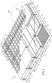
- FIG. 1 we have shown the multilayer structure of a wall 1 of a sealed and thermally insulating tank for the storage of a liquefied fluid, such as liquefied natural gas (LNG).
- a liquefied fluid such as liquefied natural gas (LNG).
- LNG liquefied natural gas
- Each wall 1 of the tank successively comprises, in the direction of thickness, from the outside towards the inside of the tank, a secondary thermally insulating barrier 2 retained on a supporting wall 3, a secondary waterproof membrane 4 resting against the secondary thermally insulating barrier 2, a primary thermally insulating barrier 5 resting against the secondary waterproof membrane 4 and a primary waterproof membrane 6 intended to be in contact with the liquefied natural gas contained in the tank.
- the supporting structure can in particular be formed by the hull or double hull of a ship.
- the supporting structure comprises a plurality of supporting walls 3 defining the general shape of the tank, usually a polyhedral shape.
- the secondary thermally insulating barrier 2 comprises a plurality of secondary insulating panels 7 which are anchored on the supporting wall 3 by means of retaining devices 98 which will be described in detail subsequently.
- the secondary insulating panels 7 have a general parallelepiped shape and are arranged in parallel rows. Three rows are indicated by the letters A, B and C.
- Rolls of putty 99 are interposed between the secondary insulating panels 7 and the supporting wall 3 to compensate for the deviations of the supporting wall 3 in relation to a flat reference surface.
- a kraft paper is inserted between rolls of putty 99 and the supporting wall 3 to prevent adhesion of the rolls of putty 99 to the supporting wall 3.
- the secondary insulating panel 7 here comprises three plates, namely a bottom plate 8, an intermediate plate 9 and a cover plate 10.
- the bottom 8, intermediate 9 and cover 10 plates are for example made of plywood.
- the secondary insulating panel 7 also comprises a first layer of insulating polymer foam 11 sandwiched between the bottom plate 8 and the intermediate plate 9 and a second layer of insulating polymer foam 12 sandwiched between the intermediate plate 9 and the base plate. cover 10.
- the first and second layers of insulating polymer foam 11, 12 are respectively glued to the bottom plate 8 and the intermediate plate 9 and to the intermediate plate 9 and the cover plate 10.
- the insulating polymer foam can in particular be a polyurethane-based foam, optionally reinforced with fibers.
- the first layer of insulating polymer foam 11 has, in the corner zones, cutouts to allow corner pillars 13 to pass through.
- the corner pillars 13 extend, at the level of the four corner zones of the secondary insulating panel 7, between the bottom plate 8 and the intermediate plate 9.
- the corner pillars 13 are fixed, for example by means of staples or screws or glue, on the bottom plate 8 and the intermediate plate 9.
- the corner pillars 13 are, for example, made of plywood or plastic.
- the corner pillars 13 make it possible to take up part of the compressive load in service and to limit the crushing and creep of the foam.
- Such corner pillars 13 have a coefficient of thermal contraction different from that of the first layer of insulating polymer foam 11. Also, when the tank is cooled, the deflection of the secondary insulating panel 7 can be lower at level of the corner pillars 13 than in the other areas.
- the secondary insulating panel 7 has recesses 14, 54 at its corner areas to receive retaining devices 98 which will be detailed later.
- the secondary insulating panel 7 comprises, from the bottom plate 8 to the intermediate plate 9, a first recess 14 intended to allow the passage of a rod 15 of the retaining device 98.
- the panel secondary insulator 7 Above the intermediate plate 9, the panel secondary insulator 7 comprises a second recess 54.
- the second recess 54 has dimensions greater than those of the first recess 14 so that the intermediate plate 9 projects beyond the second layer of insulating polymer foam 12 and the cover plate 10.
- the intermediate plate 9 forms at the corner zones of the secondary insulating panel 7 a support zone 16 intended to cooperate with a secondary support plate 17 of the retaining device 98.
- the cover plate 10 has a countersink 18 at these four corner zones. Each countersink 18 is intended to receive a force distribution plate 19 of the retaining device 98.
- the countersinks 18 have a thickness substantially similar to that of the force distribution plate 19 so that the force distribution plate 19 is flush with the upper surface of the cover plate 10.
- the cover plate 10 also has grooves 20 for receiving solder supports.
- the structure of the secondary insulating panel 7 is described above by way of example. Also, in another embodiment, the secondary insulating panels 7 are likely to have another general structure, for example that described in the document WO2012/127141 .
- the secondary insulating panels 7 are then produced in the form of a box comprising a bottom plate, a cover plate and supporting sails extending, in the direction of thickness of the tank wall 1, between the bottom plate and the cover plate and delimiting a plurality of compartments filled with an insulating filling, such as perlite, glass wool or rock wool.
- the secondary waterproof membrane 4 comprises a continuous layer of metal strakes 21, with raised edges.
- the strakes 21 are welded by their raised edges 32 on parallel welding supports which are fixed in the grooves 20 made on the cover plates 10 of the secondary insulating panels 7.
- the strakes 21 are, for example, made of Invar ® : c that is to say an alloy of iron and nickel whose coefficient of expansion is typically between 1.2.10 -6 and 2.10 -6 K -1 . It is also possible to use iron and manganese alloys whose expansion coefficient is typically of the order of 7.10 -6 K -1 .
- the primary thermally insulating barrier 5 comprises a plurality of primary insulating panels 22 which are anchored on the supporting wall 3 by means of the aforementioned retaining devices 98.
- the primary insulating panels 22 have a general parallelepiped shape. In addition, they have dimensions identical to those of the primary insulating panels 22 with the exception of their thickness in the direction of thickness of the tank wall 1 which is likely to be different, and in particular weaker.
- Each of the primary insulating panels 22 is positioned to the right of one of the secondary insulating panels 7, in alignment with the latter in the direction of thickness of the tank wall 1.
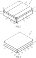
- FIG. 3 represents the structure of a primary insulating panel 22 according to one embodiment.
- the primary insulating panel 22 has a multilayer structure similar to that of the secondary insulating panel 7 of the figure 2 .
- the primary insulating panel 22 successively comprises a bottom plate 23, a first layer of insulating polymer foam 24, an intermediate plate 25, a second layer of insulating polymer foam 26 and a cover plate 27.
- the insulating polymer foam can in particular be a polyurethane-based foam, optionally reinforced with fibers.
- the primary insulating panel 22 has recesses 28 at its corner zones so that the bottom plate 23 projects beyond the first layer of insulating polymer foam 24, to the intermediate plate 25, to the second layer of insulating polymer foam 26 and the cover plate 27.
- the bottom plate 23 forms at the corner zones of the primary insulating panel 22 a support zone 29 intended to cooperate with a primary support plate 30 of the device retainer 98.
- a shim can be added to the bottom plate 23, said shim having a shape similar to that of the support zone 29 and being intended to cooperate with the primary support plate 30 of the retaining device 98.
- the bottom plate 23 has grooves 31 intended to receive the raised edges 32 of the strakes 21 of the secondary waterproof membrane 4.
- the bottom plate cover 27 may also include anchoring means, not shown on the figures 1 And 3 , to anchor the primary waterproof membrane 6.
- the structure of the primary insulating panel 22 is described above by way of example. Also, in another embodiment, the primary insulating panels 22 are likely to have another general structure, for example that described in the document WO2012/127141 .
- the primary thermally insulating barrier 5 comprises primary insulating panels 22 having at least two different types of structure, for example the two aforementioned structures, depending on their installation area in the tank.
- the primary waterproof membrane 6 comprises a continuous layer of rectangular sheets 33 which have two series of mutually perpendicular undulations.
- the first series of corrugations 55 extends perpendicular to the rows of insulating panels A, B, C and therefore perpendicular to the raised edges 32 of the strakes 21 and has a regular spacing 57.
- the second series of corrugations 56 extends parallel to the rows of insulating panels A, B, C and therefore parallel to the raised edges 32 of the strakes 21 and has a regular spacing 58.
- the first series of corrugations 55 is higher than the second series of corrugations 56.
- the rectangular sheets 33 are welded together by forming small overlapping zones 59 along their edges, according to the known technique.
- a rectangular sheet 33 preferably has width and length dimensions which are equivalent to integer multiples of the spacing of the corresponding corrugations and also integer multiples of the dimensions of the primary insulating panels 22.
- figure 1 shows a rectangular sheet 33 which measures 4 times the spacing 57 by 12 times the spacing 58.
- the spacings 57 and 58 are equal.
- the primary waterproof membrane 6 is rotated by 90° so that the first series of undulations 55 extends parallel to the rows of insulating panels A, B, C and therefore parallel to the raised edges 32 of the strakes 21.
- the primary insulating panels 22 and the secondary insulating panels 7 have the same dimension in the width direction of the rows A, B, C. This dimension will be called the length of the insulating panels by convention.
- This row width is an integer multiple of the spacing of the undulations in the same direction, here the spacing 58, and an integer multiple of the width of the strakes 21, to facilitate the manufacture of the tank wall in a modular manner by forming patterns repeated a large number of times over substantially the entire supporting wall 3.
- the width of a strake 21 is an integer multiple of the spacing of the undulations in the same direction, for example double.
- a primary insulating panel 22 may have the same dimension as a secondary insulating panel 7 or an integer multiple of this dimension.
- This dimension is an integer multiple of the spacing of the undulations in the same direction, here the spacing 57, to facilitate the manufacture of the tank wall in a modular manner by forming patterns repeated a large number of times over the entire supporting wall 3.
- the primary insulating panels 22 and the secondary insulating panels 7 are square in shape. This makes it easier to adapt the relative orientation of the strakes and corrugations in the tank without requiring significant modifications to the design of the insulating panels.
- the undulations 55 are not equidistant, but arranged in a repeated pattern of four undulations 55, the successive spacings of which are: 340; 340; 340; 180mm
- the 180 mm interval is divided into two 90 mm portions located on two opposite edges of the rectangular sheet 33.
- the dimension of the repeated pattern is therefore 1200mm.
- the dimensions of the first example are preserved.
- the undulations 55 are not equidistant, but arranged in a repeated pattern of four undulations 55, the successive spacings of which are: 300; 400; 300; 200mm
- the 200 mm interval is divided into two 100 mm portions located on two opposite edges of the rectangular sheet 33.
- the dimension of the repeated pattern is therefore 1200mm.
- the dimensions of the first example are preserved.
- the retaining devices 98 are positioned at the four corners of the primary insulating panels 22 and secondary 7.
- each stack of a secondary insulating panel 7 and a primary insulating panel 22 is anchored to the supporting wall 3 by means of four retaining devices 98.
- the retaining device 98 here comprises a primary retaining member superimposed on a secondary retaining member.
- each retaining device 98 cooperates with the corners of four adjacent secondary insulating panels 7 and with the corners of four adjacent primary insulating panels 22.
- THE figures 3 And 4 illustrate more precisely the structure of a retaining device 98 according to one embodiment.
- the retaining device 98 comprises a socket 34 whose base is welded to the supporting wall 3 in a position which corresponds to a clearance at the corner areas of four adjacent secondary insulating panels 7.
- the socket 34 houses a nut 35, shown on the Figure 4 , into which the lower end of a rod 15 is screwed.
- the rod 15 passes between the adjacent secondary insulating panels 7.
- the rod 15 passes through a bore made in an insulating plug 36 intended to ensure continuity of the secondary thermal insulation at the level of the retaining device 98.
- the insulating plug 36 presents, in a plane orthogonal to the direction of thickness of the tank wall 1, a cross-shaped section which is defined by four branches. Each of the four branches is inserted in a gap provided between two of the four adjacent secondary insulating panels 7.
- the retaining device 98 further comprises a secondary support plate 17 which bears in the direction of the supporting wall 3 against the support zone 16 formed in each of the four adjacent secondary insulating panels 7 in order to retain them against the supporting wall 3.
- the secondary support plate 17 is housed in the second recess 54 formed in the second layer of insulating polymer foam 12 of each of the secondary insulating panels 7 and is supported against a zone of the intermediate plate 9 which forms the support zone 16.
- a nut 37 cooperates with a thread provided at the upper end of the rod 15 so as to ensure retention of the secondary support plate 17 on the rod 15.
- the retaining device 98 further comprises one or more elastic washers 38, of the Belleville type.
- the elastic washers 38 are threaded onto the rod 15 between the nut 37 and the secondary support plate 17, which ensures elastic anchoring of the secondary insulating panels 7 on the supporting wall 3.
- a locking member 39 is locally welded to the upper end of the rod 15, so as to fix the nut 37 in position on the rod 15.
- the retaining device 98 further comprises a force distribution plate 19, an upper plate 40 and a spacer 41 which are fixed to the secondary support plate 17.
- the force distribution plate 19 is housed in each of the countersinks 18 provided in the cover plates 10 of the four adjacent secondary insulating panels 7.
- the force distribution plate 19 is therefore positioned between the cover plates 10 of each of the four secondary insulating panels and the secondary waterproof membrane 4.
- the force distribution plate 19 aims to attenuate the phenomena of unevenness between the corners of the insulating panels secondary 7 adjacent. Also, the force distribution plate 19 makes it possible to distribute the stresses likely to be exerted on the secondary waterproof membrane 4 and the primary insulating panels 22 to the right of the corner zones of the secondary insulating panels 7.
- the upper plate 40 is arranged below the force distribution plate 19 and has dimensions smaller than that of the force distribution plate 19 so that the force distribution plate 19 completely covers the upper plate 40.
- upper plate 40 is housed in the recesses 15 provided in the corner zones of the secondary insulating panels 7, to the right of the support zones 16, that is to say in the embodiment shown on the Figure 4 , in the recesses 54 made in the second layer of insulating polymer foam 12 of the secondary insulating panels 7.
- the upper plate 40 has a threaded bore 42 in which is mounted a threaded base of a stud 43 intended for anchoring the primary insulating panels 22.
- the distribution plate forces 19 also includes a bore, provided facing the threaded bore of the upper plate 40, and thus allowing the stud 43 to pass through the force distribution plate 19.
- the upper plate 40 and the force distribution plate 19 can be formed in a single single piece.
- the spacer 41 is arranged between the secondary support plate 17 and the upper plate and thus serves to maintain a spacing between the secondary support plate 17 and the upper plate 40.
- the spacer 41 has chamfers 45 in order to fit into the overall dimensions, seen in the direction of thickness of the tank wall 1, of the upper plate 40. In other words, the upper plate 40 completely covers the spacer 41.
- the spacer 41 is advantageously made of wood which makes it possible to limit the thermal bridge towards the supporting wall 3 at the level of the retaining device 98.
- the spacer 41 has an inverted U shape so as to define between the two branches of the U a central housing 46.
- the central housing 46 receives the upper end of the rod 15, the locking member 39, the nut 37 and the elastic washers 38.
- the spacer 41 is also housed in the recess 15 made, at the right of the support surface 16.
- the locking member 39 has a square or rectangular shape whose diagonal has a dimension greater than the dimension of the central housing 46 between the two branches of the U, which makes it possible to lock the rod 15 in rotation relative to the spacer 39 and thus prevents the rod 15 from disengaging from the nut 35.
- the aforementioned elements are each provided with two bores through each of which a screw passes 47, 48.
- the bores formed in the secondary support plate 17 each have a thread cooperating with one of the screws 47, 48 so as to ensure the fixing of the aforementioned elements to each other.
- the stud 43 passes through a hole made through a strake 21 of the secondary waterproof membrane 4.
- the stud 43 has a collar 49 which is welded to its periphery, around the hole, to ensure the tightness of the secondary waterproof membrane 4.
- the secondary waterproof membrane is therefore sandwiched between the flange 49 of the stud 43 and the force distribution plate 19.
- the retaining device 98 also comprises a primary support plate 30 which is supported in the direction of the supporting wall 3 on a support zone 29 provided in each of the four adjacent primary insulating panels 22 so as to retain them against the wall carrier 3.
- each support zone 29 is formed by an overhanging part of the bottom plate 23 of one of the primary insulating panels 22.
- the primary support plate 30 is housed in the recesses 28 provided in the corner zones of the primary insulating panels 22, to the right of the support zones 29.
- a nut 50 cooperates with a thread provided at the upper end of the stud 43 so as to ensure the fixing of the primary support plate 30 on the stud 43.
- the retaining device 98 comprises in addition one or more elastic washers 51, of the Belleville type, which are threaded onto the stud 43 between the nut 50 and the primary support plate 30, which ensures elastic anchoring of the primary insulating panels 22 on the load-bearing wall 3.
- an insulating plug 52 illustrated on the Figure 4
- an insulating plug 52 is inserted above the retaining device 98 in the recesses 28 provided at the corner zones of four adjacent primary insulating panels 22 so as to ensure continuity of the primary thermally insulating barrier 5 at the level of the retaining device 98.
- a closing plate 53 made of wood, illustrated on the Figure 4 makes it possible to ensure flatness of the support surface of the primary waterproof membrane 6. The closing plate 53 is received in countersinks provided at the corner areas of the primary insulating panels 22.
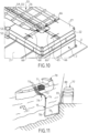
- metal anchoring strips 60 are fixed on the cover plates 27 of the insulating panels primaries 22 at the locations of the contours of the rectangular sheets 33.
- the edges of the rectangular sheets 33 can thus be fixed by welding along the anchoring strips 60.
- the anchoring strip 60 is fixed in a countersink on the cover plate 27 by any suitable means, for example screws or rivets.
- THE figures 6 and 7 also show metal plates 61 which can be fixed to the cover plates 27 of the primary insulating panels 22 at other locations, for example along the edges of the primary insulating panels 22 which are spaced from the contours of the rectangular sheets 33, to provide additional fixing points.
- a metal plate 61 is fixed in a countersink on the cover plate 27 by any suitable means, for example screws or rivets.
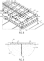
- THE figures 8 and 9 show another embodiment of the primary insulating panels 22, the edges of which have countersinks 63 to receive bridging plates 64, for example made of plywood.
- the bridging plates 64 are fixed to the cover plates 27 of two primary insulating panels 22 to avoid a separation of the two primary insulating panels 22 at the interface 62 and thus improve the uniformity of the support surface where the membrane rests primary waterproof 6.
- the cover plates 27 and the layers of insulating polymer foam 26 are provided with relaxation slots 65 which segment the cover plates 27 and the layers of insulating polymer foam 26 into several parts and thus avoid cracking during cooling .
- FIG. 10 shows another embodiment of the primary insulating panels 22, in which the relaxation slots 65 are limited to an area neighboring the anchoring strips 60, as described in the publication FR-A-3001945 .
- Thermal protection strips 66 are arranged in alignment with the anchoring strips 60, to the right of certain parts of the contours of the rectangular sheets 33, to avoid damaging the cover plate 27 when carrying out the welds.
- the tank wall 101 shown on the Figure 12 illustrates an embodiment in which a row of primary insulating panels 22 is superimposed, not on a single row of secondary insulating panels 7, but straddling two rows of secondary insulating panels 7.
- the elements identical or similar to the elements of the figures 1 to 10 bear the same reference number as these and will only be described to the extent that they differ.
- the secondary retaining member can be made in various ways, for example as the retaining device 98 from which all the elements arranged above the distribution plate 19 will have been removed. distribution of forces 19 and the counterbore 18 intended to receive it can also be removed.
- the secondary retaining members can be in various numbers ranging for example from 2 to 5 per secondary insulating panel 7 and placed for example at the corners of the secondary panels and/or in the gap between two secondary panels, either according to the first direction or according to the second direction. Other embodiments of the secondary retainer are described in WO-A-2013093262 .
- the primary retainer 97 can be made in various ways, for example as illustrated in the enlarged view of the Figure 13 or as described in the publication FR-A-2887010 .
- the primary retaining member 97 comprises a plate 119, for example having a square or circular outline, which is fixed in a countersink formed in the surface of the cover plate 10 facing the layer of insulating polymer foam 11, for example by gluing.
- the plate 119 has a threaded hole opening into the upper surface of the cover plate 10 into which a stud 143 identical to the stud 43 described above can be screwed.
- the entire primary stage of the tank wall namely the primary thermally insulating barrier 5 and the primary waterproof membrane 6 which it carries, has been offset in both directions of the plane by half the length of a secondary insulating panel 7.
- the primary retaining member 97 is in the center of the cover plate of a secondary insulating panel 7.
- a secondary retaining member still cooperates with the corners of four adjacent secondary insulating panels 7 and a primary retaining member 97 still cooperates with the corners of four adjacent primary insulating panels 22.
- the magnitude of the offset could be different and the primary retainer 97 could be elsewhere on the cover plate of a secondary insulating panel 7, but preferably at a distance from the raised edges 32 so as not to interfere with them.
- the amplitude of the offset can be different in the two directions of the plane.
- the tank wall 201 sketched on the Figure 14 illustrates an embodiment in which a row of primary insulating panels 22 is superimposed on a row of secondary insulating panels 7, but offset in the first direction by a fraction of the length of an insulating panel, here half of this length.
- a primary insulating panel 22 of the primary row straddles two secondary insulating panels 7 of the underlying secondary row.
- Elements identical or similar to the elements of the figures 1 to 13 bear the same reference number as these and will only be described to the extent that they differ.
- the primary insulating panels 22 are retained on the secondary waterproof membrane, not shown, by retaining members arranged in the middle of the sides of the primary insulating panels 22.
- the primary retaining member 97 arranged in the center of the cover plate of the secondary insulating panel 7 cooperates with two primary insulating panels 22 of the primary row and is located at mid-width of the primary row.
- the secondary retaining members 92 at the corners of the secondary insulating panels 7 there are secondary retaining members 92, as in the previous embodiments.
- the secondary retainer 92 carries a primary retainer 91.
- the secondary retainer 92 and the primary retainer 91 which it carries can be made similarly to the retainer 98 or differently.
- the primary retaining member 91 cooperates here with only two primary insulating panels 22, at the middle of one side of these primary insulating panels 22.
- the shape of the primary insulating panels 22 can be configured to provide an access chimney 93.
- the chimney 93 is closed after installation of the member primary retainer 91, for example with a polyurethane foam plug covered with a rigid plate, for example plywood (not shown).
- the primary waterproof membrane in which the undulations are continuous at the level of the intersections between the two series of undulations.
- the primary waterproof membrane can also have two series of mutually perpendicular undulations with discontinuities of certain undulations at the intersections between the two series.
- the interruptions are distributed alternately in the first series of undulations and the second series of undulations and, within a series of undulations, the interruptions of one undulation are offset relative to the interruptions of one undulation adjacent parallel. This offset can be equal to the spacing between two parallel undulations.
- a cutaway view of an LNG ship 70 shows a watertight and insulated tank 71 of generally prismatic shape mounted in the double hull 72 of the ship.
- the wall of the tank 71 comprises a primary waterproof barrier intended to be in contact with the LNG contained in the tank, a secondary waterproof barrier arranged between the primary waterproof barrier and the double hull 72 of the ship, and two insulating barriers arranged respectively between the primary waterproof barrier and the secondary waterproof barrier and between the secondary waterproof barrier and the double hull 72.
- loading/unloading pipes 73 arranged on the upper deck of the ship can be connected, by means of appropriate connectors, to a maritime or port terminal to transfer a cargo of LNG from or to the tank 71.
- FIG. 11 represents an example of a maritime terminal comprising a loading and unloading station 75, an underwater pipe 76 and an onshore installation 77.
- the loading and unloading station 75 is a fixed off-shore installation comprising a movable arm 74 and a tower 78 which supports the mobile arm 74.
- the mobile arm 74 carries a bundle of insulated flexible pipes 79 which can connect to the loading/unloading pipes 73.
- the adjustable mobile arm 74 adapts to all LNG carrier templates.
- a connection pipe not shown extends inside the tower 78.
- the loading and unloading station 75 allows the loading and unloading of the LNG tanker 70 from or to the onshore installation 77.
- the underwater pipe 76 allows the transfer of the liquefied gas between the loading or unloading station 75 and the onshore installation 77 over a long distance, for example 5 km, which makes it possible to keep the LNG ship 70 at a long distance from the coast during loading and unloading operations.
- pumps on board the ship 70 and/or pumps fitted to the on-shore installation 77 and/or pumps fitted to the loading and unloading station 75 are used.
Landscapes
- Engineering & Computer Science (AREA)
- Mechanical Engineering (AREA)
- General Engineering & Computer Science (AREA)
- Physics & Mathematics (AREA)
- Thermal Sciences (AREA)
- Chemical & Material Sciences (AREA)
- Combustion & Propulsion (AREA)
- Ocean & Marine Engineering (AREA)
- Filling Or Discharging Of Gas Storage Vessels (AREA)
- Loading And Unloading Of Fuel Tanks Or Ships (AREA)
Applications Claiming Priority (3)
| Application Number | Priority Date | Filing Date | Title |
|---|---|---|---|
| FR1854925A FR3082274B1 (fr) | 2018-06-06 | 2018-06-06 | Cuve etanche et thermiquement isolante |
| FR1858144A FR3082275B1 (fr) | 2018-06-06 | 2018-09-11 | Cuve etanche et thermiquement isolante |
| PCT/FR2019/051358 WO2019234360A2 (fr) | 2018-06-06 | 2019-06-06 | Cuve etanche et thermiquement isolante |
Publications (2)
| Publication Number | Publication Date |
|---|---|
| EP3803187A2 EP3803187A2 (fr) | 2021-04-14 |
| EP3803187B1 true EP3803187B1 (fr) | 2024-08-07 |
Family
ID=63491649
Family Applications (1)
| Application Number | Title | Priority Date | Filing Date |
|---|---|---|---|
| EP19737849.0A Active EP3803187B1 (fr) | 2018-06-06 | 2019-06-06 | Cuve etanche et thermiquement isolante |
Country Status (13)
| Country | Link |
|---|---|
| US (2) | US11543078B2 (https=) |
| EP (1) | EP3803187B1 (https=) |
| JP (2) | JP7241777B2 (https=) |
| KR (2) | KR20250021388A (https=) |
| CN (2) | CN116428506A (https=) |
| AU (1) | AU2019282394B2 (https=) |
| DK (1) | DK3803187T3 (https=) |
| ES (1) | ES2992131T3 (https=) |
| FR (2) | FR3082274B1 (https=) |
| PH (1) | PH12020552090A1 (https=) |
| PT (1) | PT3803187T (https=) |
| SG (1) | SG11202012115SA (https=) |
| WO (1) | WO2019234360A2 (https=) |
Families Citing this family (17)
| Publication number | Priority date | Publication date | Assignee | Title |
|---|---|---|---|---|
| FR3082274B1 (fr) * | 2018-06-06 | 2021-11-19 | Gaztransport Et Technigaz | Cuve etanche et thermiquement isolante |
| FR3110951B1 (fr) * | 2020-05-26 | 2022-05-06 | Gaztransport Et Technigaz | Dispositif d’ancrage destine a retenir des blocs isolants |
| FR3111178B1 (fr) | 2020-06-03 | 2022-05-06 | Gaztransport Et Technigaz | Cuve étanche et thermiquement isolante intégrée dans une structure porteuse |
| FR3115091B1 (fr) * | 2020-10-09 | 2022-08-26 | Gaztransport Et Technigaz | Cuve étanche et thermiquement isolante |
| FR3115092B1 (fr) * | 2020-10-09 | 2023-04-21 | Gaztransport Et Technigaz | Cuve étanche et thermiquement isolante |
| FR3125323B1 (fr) | 2021-07-19 | 2023-06-16 | Gaztransport Et Technigaz | Installation de stockage pour gaz liquéfié |
| FR3126395B1 (fr) | 2021-08-24 | 2024-05-10 | Gaztransport Et Technigaz | Installation de stockage pour gaz liquéfié |
| CN114509223B (zh) * | 2021-12-29 | 2024-08-20 | 海洋石油工程股份有限公司 | 一种应用于lng罐内壁板焊缝真空检测防水装置 |
| NO20220270A1 (en) * | 2022-03-03 | 2023-09-04 | Lattice Int As | Membrane tank feasible for cryogenic service |
| FR3139868B1 (fr) * | 2022-09-16 | 2024-08-23 | Gaztransport Et Technigaz | Bande d’ancrage et procédé de fabrication d’une telle bande d’ancrage |
| FR3143711B1 (fr) | 2022-12-16 | 2024-11-01 | Gaztransport Et Technigaz | Cuve étanche et thermiquement isolante comportant un élément traversant |
| FR3143712B1 (fr) | 2022-12-16 | 2024-11-01 | Gaztransport Et Technigaz | Cuve étanche et thermiquement isolante comportant un élément traversant |
| FR3151372B1 (fr) | 2023-07-20 | 2025-10-10 | Gaztransport Et Technigaz | Cuve étanche et thermiquement isolante comprenant des plaques de pontage |
| FR3151371B1 (fr) * | 2023-07-20 | 2025-06-13 | Gaztransport Et Technigaz | Cuve étanche et thermiquement isolante comprenant un panneau isolant |
| CN117553221A (zh) * | 2023-12-05 | 2024-02-13 | 利衡新型储能装备制造(安徽)有限公司 | 一种带有伸缩波的圆筒形硐室衬里 |
| CN117818844B (zh) * | 2024-03-06 | 2024-06-11 | 沪东中华造船(集团)有限公司 | 一种低温液货存储运输用薄膜型围护系统的安装方法 |
| FR3161719B1 (fr) | 2024-04-26 | 2026-03-13 | Gaztransport Et Technigaz | Bloc modulaire pour paroi de cuve |
Family Cites Families (27)
| Publication number | Priority date | Publication date | Assignee | Title |
|---|---|---|---|---|
| FR2504882B1 (fr) * | 1981-04-30 | 1985-11-08 | Gaz Transport | Cuve etanche et thermiquement isolante integree a la structure porteuse d'un navire |
| KR880002146A (ko) * | 1986-07-12 | 1988-04-29 | 한형수 | 비디오 디스크플레이어의 포커스 서보게 |
| FR2629897B1 (fr) | 1988-04-08 | 1991-02-15 | Gaz Transport | Cuve etanche et thermiquement isolante perfectionnee, integree a la structure porteuse d'un navire |
| AU2004291042B2 (en) | 2003-11-14 | 2010-10-14 | Essilor International (Compagnie Generale D'optique) | Ophthalmic binocular wafefront measurement system |
| JP4616279B2 (ja) * | 2004-12-08 | 2011-01-19 | コリア ガス コーポレイション | 液化天然ガスの保存タンク及びその製造方法 |
| FR2887010B1 (fr) | 2005-06-10 | 2007-08-10 | Gaz Transp Et Technigaz Soc Pa | Cuve etanche et thermiquement isolee |
| WO2008007837A1 (en) * | 2006-07-11 | 2008-01-17 | Hyundai Heavy Industries Co., Ltd. | Seam butt type insulation system having weldable secondary barrier for lng tanks |
| CN101688640B (zh) * | 2007-05-29 | 2011-06-08 | 现代重工业株式会社 | 具有焊接的次防壁的液化天然气储存箱绝热系统及其构造方法 |
| EP3000885B1 (en) | 2009-12-18 | 2018-07-25 | Arrowhead Pharmaceuticals, Inc. | Organic compositions to treat hsf1-related diseases |
| FR2973097B1 (fr) | 2011-03-23 | 2013-04-12 | Gaztransp Et Technigaz | Element calorifuge pour paroi de cuve etanche et thermiquement isolante |
| FR2984992B1 (fr) | 2011-12-21 | 2015-03-27 | Gaztransp Et Technigaz | Cuve etanche et isolante munie d'un dispositif de retenue |
| CN102915185B (zh) | 2012-09-20 | 2018-11-16 | 广州市动景计算机科技有限公司 | 应用界面及控制应用界面操作的方法和装置 |
| KR101794359B1 (ko) * | 2012-10-04 | 2017-11-06 | 현대중공업 주식회사 | 액화천연가스 운반선의 탱크 내벽 구조 |
| FR2996520B1 (fr) | 2012-10-09 | 2014-10-24 | Gaztransp Et Technigaz | Cuve etanche et thermiquement isolante comportant une membrane metalique ondulee selon des plis orthogonaux |
| FR3001945B1 (fr) | 2013-02-14 | 2017-04-28 | Gaztransport Et Technigaz | Paroi etanche et thermiquement isolante pour cuve de stockage de fluide |
| FR3004510B1 (fr) * | 2013-04-12 | 2016-12-09 | Gaztransport Et Technigaz | Cuve etanche et thermiquement isolante de stockage d'un fluide |
| KR102297860B1 (ko) | 2014-09-22 | 2021-09-03 | 대우조선해양 주식회사 | 액화천연가스 화물창 단열 시스템 |
| FR3026459B1 (fr) | 2014-09-26 | 2017-06-09 | Gaztransport Et Technigaz | Cuve etanche et isolante comportant un element de pontage entre les panneaux de la barriere isolante secondaire |
| KR101672209B1 (ko) * | 2014-10-23 | 2016-11-04 | 삼성중공업 주식회사 | 액화가스 화물창 |
| FR3035175B1 (fr) | 2015-04-20 | 2017-04-28 | Gaztransport Et Technigaz | Cuve etanche et thermiquement isolante equipee d'un element traversant |
| FR3039248B1 (fr) * | 2015-07-24 | 2017-08-18 | Gaztransport Et Technigaz | Cuve etanche et thermiquement isolante munie d'une piece de renfort |
| KR101751838B1 (ko) * | 2015-08-21 | 2017-07-19 | 대우조선해양 주식회사 | 앵커 스트립이 제거된 액화가스 화물창의 인슐레이션 구조, 그 인슐레이션 구조를 구비하는 화물창, 및 그 화물창을 구비하는 액화가스 운반선 |
| FR3042253B1 (fr) | 2015-10-13 | 2018-05-18 | Gaztransport Et Technigaz | Cuve etanche et thermiquement isolante |
| FR3042843B1 (fr) * | 2015-10-23 | 2018-04-27 | Gaztransport Et Technigaz | Cuve comprenant des blocs isolants de coin equipes de fentes de relaxation |
| KR20180108727A (ko) * | 2016-02-02 | 2018-10-04 | 아이씨 테크놀로지 에이에스 | 개선된 액화 천연 가스 저장 탱크 설계 |
| FR3070747B1 (fr) | 2017-09-04 | 2021-01-08 | Gaztransport Et Technigaz | Cuve etanche et thermiquement isolante comportant une bande de couverture anti-convective |
| FR3082274B1 (fr) * | 2018-06-06 | 2021-11-19 | Gaztransport Et Technigaz | Cuve etanche et thermiquement isolante |
-
2018
- 2018-06-06 FR FR1854925A patent/FR3082274B1/fr active Active
- 2018-09-11 FR FR1858144A patent/FR3082275B1/fr active Active
-
2019
- 2019-06-06 CN CN202211653798.0A patent/CN116428506A/zh active Pending
- 2019-06-06 PT PT197378490T patent/PT3803187T/pt unknown
- 2019-06-06 DK DK19737849.0T patent/DK3803187T3/da active
- 2019-06-06 ES ES19737849T patent/ES2992131T3/es active Active
- 2019-06-06 JP JP2020567483A patent/JP7241777B2/ja active Active
- 2019-06-06 KR KR1020257001876A patent/KR20250021388A/ko active Pending
- 2019-06-06 KR KR1020207037042A patent/KR102758691B1/ko active Active
- 2019-06-06 EP EP19737849.0A patent/EP3803187B1/fr active Active
- 2019-06-06 AU AU2019282394A patent/AU2019282394B2/en active Active
- 2019-06-06 US US15/734,990 patent/US11543078B2/en active Active
- 2019-06-06 CN CN201980054529.2A patent/CN112639351B/zh active Active
- 2019-06-06 SG SG11202012115SA patent/SG11202012115SA/en unknown
- 2019-06-06 WO PCT/FR2019/051358 patent/WO2019234360A2/fr not_active Ceased
-
2020
- 2020-12-04 PH PH12020552090A patent/PH12020552090A1/en unknown
-
2022
- 2022-11-15 US US17/987,354 patent/US11796131B2/en active Active
-
2023
- 2023-03-07 JP JP2023034215A patent/JP7681053B2/ja active Active
Also Published As
| Publication number | Publication date |
|---|---|
| FR3082275B1 (fr) | 2022-05-20 |
| JP7681053B2 (ja) | 2025-05-21 |
| JP2021527781A (ja) | 2021-10-14 |
| WO2019234360A3 (fr) | 2020-03-05 |
| CN116428506A (zh) | 2023-07-14 |
| FR3082274B1 (fr) | 2021-11-19 |
| KR20250021388A (ko) | 2025-02-12 |
| FR3082274A1 (fr) | 2019-12-13 |
| AU2019282394A1 (en) | 2021-01-07 |
| SG11202012115SA (en) | 2021-01-28 |
| EP3803187A2 (fr) | 2021-04-14 |
| DK3803187T3 (da) | 2024-10-28 |
| WO2019234360A2 (fr) | 2019-12-12 |
| KR102758691B1 (ko) | 2025-01-22 |
| PT3803187T (pt) | 2024-09-05 |
| CN112639351B (zh) | 2023-01-06 |
| ES2992131T3 (es) | 2024-12-09 |
| KR20210016561A (ko) | 2021-02-16 |
| FR3082275A1 (fr) | 2019-12-13 |
| US11543078B2 (en) | 2023-01-03 |
| AU2019282394B2 (en) | 2024-10-03 |
| JP7241777B2 (ja) | 2023-03-17 |
| US20230076501A1 (en) | 2023-03-09 |
| PH12020552090A1 (en) | 2021-05-31 |
| US11796131B2 (en) | 2023-10-24 |
| JP2023081965A (ja) | 2023-06-13 |
| CN112639351A (zh) | 2021-04-09 |
| US20210231262A1 (en) | 2021-07-29 |
Similar Documents
| Publication | Publication Date | Title |
|---|---|---|
| EP3803187B1 (fr) | Cuve etanche et thermiquement isolante | |
| EP3362732B1 (fr) | Cuve étanche et thermiquement isolante | |
| EP3320256B1 (fr) | Cuve etanche et thermiquement isolante ayant une membrane d'etancheite secondaire equipee d'un arrangement d'angle a toles metalliques ondulees | |
| FR3058498B1 (fr) | Structure d'angle d'une cuve etanche et thermiquement isolante et son procede d'assemblage | |
| EP3198186B1 (fr) | Cuve étanche et isolante comportant un élément de pontage entre les panneaux de la barrière isolante secondaire | |
| EP3365592B1 (fr) | Cuve comprenant des blocs isolants de coin equipes de fentes de relaxation | |
| WO2019110894A1 (fr) | Cuve étanche et thermiquement isolante | |
| WO2020039134A1 (fr) | Paroi de cuve étanche et thermiquement isolante | |
| WO2016166481A2 (fr) | Cuve équipée d'une paroi présentant une zone singulière au travers de laquelle passe un élément traversant | |
| WO2017207938A1 (fr) | Bloc isolant et cuve etanche et thermiquement isolante integree dans une structure porteuse polyedrique | |
| EP2986885B1 (fr) | Cuve étanche et thermiquement isolante | |
| WO2022074148A1 (fr) | Cuve étanche et thermiquement isolante | |
| WO2017207904A1 (fr) | Cuve etanche et thermiquement isolante integree dans une structure porteuse polyedrique | |
| WO2022074226A1 (fr) | Cuve étanche et thermiquement isolante | |
| WO2023025501A1 (fr) | Installation de stockage pour gaz liquéfié | |
| WO2020115406A1 (fr) | Cuve etanche et thermiquement isolante | |
| WO2022053320A1 (fr) | Cuve étanche et thermiquement isolante | |
| WO2024125849A1 (fr) | Cuve étanche et thermiquement isolante comportant un élément traversant | |
| WO2021245091A1 (fr) | Cuve étanche et thermiquement isolante intégrée dans une structure porteuse | |
| FR3094452A1 (fr) | Installation de stockage pour gaz liquéfié | |
| EP3526512B1 (fr) | Cuve étanche et thermiquement isolante | |
| WO2024125850A1 (fr) | Cuve étanche et thermiquement isolante comportant un élément traversant |
Legal Events
| Date | Code | Title | Description |
|---|---|---|---|
| STAA | Information on the status of an ep patent application or granted ep patent |
Free format text: STATUS: UNKNOWN |
|
| STAA | Information on the status of an ep patent application or granted ep patent |
Free format text: STATUS: THE INTERNATIONAL PUBLICATION HAS BEEN MADE |
|
| PUAI | Public reference made under article 153(3) epc to a published international application that has entered the european phase |
Free format text: ORIGINAL CODE: 0009012 |
|
| STAA | Information on the status of an ep patent application or granted ep patent |
Free format text: STATUS: REQUEST FOR EXAMINATION WAS MADE |
|
| 17P | Request for examination filed |
Effective date: 20201223 |
|
| AK | Designated contracting states |
Kind code of ref document: A2 Designated state(s): AL AT BE BG CH CY CZ DE DK EE ES FI FR GB GR HR HU IE IS IT LI LT LU LV MC MK MT NL NO PL PT RO RS SE SI SK SM TR |
|
| AX | Request for extension of the european patent |
Extension state: BA ME |
|
| DAV | Request for validation of the european patent (deleted) | ||
| DAX | Request for extension of the european patent (deleted) | ||
| GRAP | Despatch of communication of intention to grant a patent |
Free format text: ORIGINAL CODE: EPIDOSNIGR1 |
|
| STAA | Information on the status of an ep patent application or granted ep patent |
Free format text: STATUS: GRANT OF PATENT IS INTENDED |
|
| INTG | Intention to grant announced |
Effective date: 20240313 |
|
| GRAS | Grant fee paid |
Free format text: ORIGINAL CODE: EPIDOSNIGR3 |
|
| GRAA | (expected) grant |
Free format text: ORIGINAL CODE: 0009210 |
|
| STAA | Information on the status of an ep patent application or granted ep patent |
Free format text: STATUS: THE PATENT HAS BEEN GRANTED |
|
| AK | Designated contracting states |
Kind code of ref document: B1 Designated state(s): AL AT BE BG CH CY CZ DE DK EE ES FI FR GB GR HR HU IE IS IT LI LT LU LV MC MK MT NL NO PL PT RO RS SE SI SK SM TR |
|
| REG | Reference to a national code |
Ref country code: GB Ref legal event code: FG4D Free format text: NOT ENGLISH |
|
| REG | Reference to a national code |
Ref country code: CH Ref legal event code: EP |
|
| REG | Reference to a national code |
Ref country code: IE Ref legal event code: FG4D Free format text: LANGUAGE OF EP DOCUMENT: FRENCH |
|
| REG | Reference to a national code |
Ref country code: DE Ref legal event code: R096 Ref document number: 602019056582 Country of ref document: DE |
|
| REG | Reference to a national code |
Ref country code: PT Ref legal event code: SC4A Ref document number: 3803187 Country of ref document: PT Date of ref document: 20240905 Kind code of ref document: T Free format text: AVAILABILITY OF NATIONAL TRANSLATION Effective date: 20240829 |
|
| REG | Reference to a national code |
Ref country code: DK Ref legal event code: T3 Effective date: 20241025 |
|
| REG | Reference to a national code |
Ref country code: LT Ref legal event code: MG9D |
|
| REG | Reference to a national code |
Ref country code: ES Ref legal event code: FG2A Ref document number: 2992131 Country of ref document: ES Kind code of ref document: T3 Effective date: 20241209 |
|
| REG | Reference to a national code |
Ref country code: NL Ref legal event code: MP Effective date: 20240807 |
|
| PG25 | Lapsed in a contracting state [announced via postgrant information from national office to epo] |
Ref country code: NO Free format text: LAPSE BECAUSE OF FAILURE TO SUBMIT A TRANSLATION OF THE DESCRIPTION OR TO PAY THE FEE WITHIN THE PRESCRIBED TIME-LIMIT Effective date: 20241107 |
|
| REG | Reference to a national code |
Ref country code: AT Ref legal event code: MK05 Ref document number: 1711298 Country of ref document: AT Kind code of ref document: T Effective date: 20240807 |
|
| PG25 | Lapsed in a contracting state [announced via postgrant information from national office to epo] |
Ref country code: FI Free format text: LAPSE BECAUSE OF FAILURE TO SUBMIT A TRANSLATION OF THE DESCRIPTION OR TO PAY THE FEE WITHIN THE PRESCRIBED TIME-LIMIT Effective date: 20240807 Ref country code: NL Free format text: LAPSE BECAUSE OF FAILURE TO SUBMIT A TRANSLATION OF THE DESCRIPTION OR TO PAY THE FEE WITHIN THE PRESCRIBED TIME-LIMIT Effective date: 20240807 Ref country code: PL Free format text: LAPSE BECAUSE OF FAILURE TO SUBMIT A TRANSLATION OF THE DESCRIPTION OR TO PAY THE FEE WITHIN THE PRESCRIBED TIME-LIMIT Effective date: 20240807 Ref country code: GR Free format text: LAPSE BECAUSE OF FAILURE TO SUBMIT A TRANSLATION OF THE DESCRIPTION OR TO PAY THE FEE WITHIN THE PRESCRIBED TIME-LIMIT Effective date: 20241108 |
|
| PG25 | Lapsed in a contracting state [announced via postgrant information from national office to epo] |
Ref country code: BG Free format text: LAPSE BECAUSE OF FAILURE TO SUBMIT A TRANSLATION OF THE DESCRIPTION OR TO PAY THE FEE WITHIN THE PRESCRIBED TIME-LIMIT Effective date: 20240807 |
|
| PG25 | Lapsed in a contracting state [announced via postgrant information from national office to epo] |
Ref country code: LV Free format text: LAPSE BECAUSE OF FAILURE TO SUBMIT A TRANSLATION OF THE DESCRIPTION OR TO PAY THE FEE WITHIN THE PRESCRIBED TIME-LIMIT Effective date: 20240807 |
|
| PG25 | Lapsed in a contracting state [announced via postgrant information from national office to epo] |
Ref country code: AT Free format text: LAPSE BECAUSE OF FAILURE TO SUBMIT A TRANSLATION OF THE DESCRIPTION OR TO PAY THE FEE WITHIN THE PRESCRIBED TIME-LIMIT Effective date: 20240807 Ref country code: IS Free format text: LAPSE BECAUSE OF FAILURE TO SUBMIT A TRANSLATION OF THE DESCRIPTION OR TO PAY THE FEE WITHIN THE PRESCRIBED TIME-LIMIT Effective date: 20241207 |
|
| PG25 | Lapsed in a contracting state [announced via postgrant information from national office to epo] |
Ref country code: HR Free format text: LAPSE BECAUSE OF FAILURE TO SUBMIT A TRANSLATION OF THE DESCRIPTION OR TO PAY THE FEE WITHIN THE PRESCRIBED TIME-LIMIT Effective date: 20240807 |
|
| PG25 | Lapsed in a contracting state [announced via postgrant information from national office to epo] |
Ref country code: RS Free format text: LAPSE BECAUSE OF FAILURE TO SUBMIT A TRANSLATION OF THE DESCRIPTION OR TO PAY THE FEE WITHIN THE PRESCRIBED TIME-LIMIT Effective date: 20241107 |
|
| PG25 | Lapsed in a contracting state [announced via postgrant information from national office to epo] |
Ref country code: RS Free format text: LAPSE BECAUSE OF FAILURE TO SUBMIT A TRANSLATION OF THE DESCRIPTION OR TO PAY THE FEE WITHIN THE PRESCRIBED TIME-LIMIT Effective date: 20241107 Ref country code: PL Free format text: LAPSE BECAUSE OF FAILURE TO SUBMIT A TRANSLATION OF THE DESCRIPTION OR TO PAY THE FEE WITHIN THE PRESCRIBED TIME-LIMIT Effective date: 20240807 Ref country code: NO Free format text: LAPSE BECAUSE OF FAILURE TO SUBMIT A TRANSLATION OF THE DESCRIPTION OR TO PAY THE FEE WITHIN THE PRESCRIBED TIME-LIMIT Effective date: 20241107 Ref country code: NL Free format text: LAPSE BECAUSE OF FAILURE TO SUBMIT A TRANSLATION OF THE DESCRIPTION OR TO PAY THE FEE WITHIN THE PRESCRIBED TIME-LIMIT Effective date: 20240807 Ref country code: LV Free format text: LAPSE BECAUSE OF FAILURE TO SUBMIT A TRANSLATION OF THE DESCRIPTION OR TO PAY THE FEE WITHIN THE PRESCRIBED TIME-LIMIT Effective date: 20240807 Ref country code: IS Free format text: LAPSE BECAUSE OF FAILURE TO SUBMIT A TRANSLATION OF THE DESCRIPTION OR TO PAY THE FEE WITHIN THE PRESCRIBED TIME-LIMIT Effective date: 20241207 Ref country code: HR Free format text: LAPSE BECAUSE OF FAILURE TO SUBMIT A TRANSLATION OF THE DESCRIPTION OR TO PAY THE FEE WITHIN THE PRESCRIBED TIME-LIMIT Effective date: 20240807 Ref country code: GR Free format text: LAPSE BECAUSE OF FAILURE TO SUBMIT A TRANSLATION OF THE DESCRIPTION OR TO PAY THE FEE WITHIN THE PRESCRIBED TIME-LIMIT Effective date: 20241108 Ref country code: FI Free format text: LAPSE BECAUSE OF FAILURE TO SUBMIT A TRANSLATION OF THE DESCRIPTION OR TO PAY THE FEE WITHIN THE PRESCRIBED TIME-LIMIT Effective date: 20240807 Ref country code: BG Free format text: LAPSE BECAUSE OF FAILURE TO SUBMIT A TRANSLATION OF THE DESCRIPTION OR TO PAY THE FEE WITHIN THE PRESCRIBED TIME-LIMIT Effective date: 20240807 Ref country code: AT Free format text: LAPSE BECAUSE OF FAILURE TO SUBMIT A TRANSLATION OF THE DESCRIPTION OR TO PAY THE FEE WITHIN THE PRESCRIBED TIME-LIMIT Effective date: 20240807 |
|
| PG25 | Lapsed in a contracting state [announced via postgrant information from national office to epo] |
Ref country code: RO Free format text: LAPSE BECAUSE OF FAILURE TO SUBMIT A TRANSLATION OF THE DESCRIPTION OR TO PAY THE FEE WITHIN THE PRESCRIBED TIME-LIMIT Effective date: 20240807 Ref country code: SM Free format text: LAPSE BECAUSE OF FAILURE TO SUBMIT A TRANSLATION OF THE DESCRIPTION OR TO PAY THE FEE WITHIN THE PRESCRIBED TIME-LIMIT Effective date: 20240807 |
|
| PG25 | Lapsed in a contracting state [announced via postgrant information from national office to epo] |
Ref country code: EE Free format text: LAPSE BECAUSE OF FAILURE TO SUBMIT A TRANSLATION OF THE DESCRIPTION OR TO PAY THE FEE WITHIN THE PRESCRIBED TIME-LIMIT Effective date: 20240807 |
|
| PG25 | Lapsed in a contracting state [announced via postgrant information from national office to epo] |
Ref country code: CZ Free format text: LAPSE BECAUSE OF FAILURE TO SUBMIT A TRANSLATION OF THE DESCRIPTION OR TO PAY THE FEE WITHIN THE PRESCRIBED TIME-LIMIT Effective date: 20240807 |
|
| PG25 | Lapsed in a contracting state [announced via postgrant information from national office to epo] |
Ref country code: SK Free format text: LAPSE BECAUSE OF FAILURE TO SUBMIT A TRANSLATION OF THE DESCRIPTION OR TO PAY THE FEE WITHIN THE PRESCRIBED TIME-LIMIT Effective date: 20240807 |
|
| REG | Reference to a national code |
Ref country code: DE Ref legal event code: R097 Ref document number: 602019056582 Country of ref document: DE |
|
| PLBE | No opposition filed within time limit |
Free format text: ORIGINAL CODE: 0009261 |
|
| STAA | Information on the status of an ep patent application or granted ep patent |
Free format text: STATUS: NO OPPOSITION FILED WITHIN TIME LIMIT |
|
| PGFP | Annual fee paid to national office [announced via postgrant information from national office to epo] |
Ref country code: DK Payment date: 20250527 Year of fee payment: 7 |
|
| 26N | No opposition filed |
Effective date: 20250508 |
|
| PGFP | Annual fee paid to national office [announced via postgrant information from national office to epo] |
Ref country code: PT Payment date: 20250523 Year of fee payment: 7 |
|
| PGFP | Annual fee paid to national office [announced via postgrant information from national office to epo] |
Ref country code: FR Payment date: 20250630 Year of fee payment: 7 |
|
| PGFP | Annual fee paid to national office [announced via postgrant information from national office to epo] |
Ref country code: TR Payment date: 20250529 Year of fee payment: 7 |
|
| PG25 | Lapsed in a contracting state [announced via postgrant information from national office to epo] |
Ref country code: SE Free format text: LAPSE BECAUSE OF FAILURE TO SUBMIT A TRANSLATION OF THE DESCRIPTION OR TO PAY THE FEE WITHIN THE PRESCRIBED TIME-LIMIT Effective date: 20240807 |
|
| PGFP | Annual fee paid to national office [announced via postgrant information from national office to epo] |
Ref country code: ES Payment date: 20250710 Year of fee payment: 7 |
|
| REG | Reference to a national code |
Ref country code: DE Ref legal event code: R119 Ref document number: 602019056582 Country of ref document: DE |
|
| REG | Reference to a national code |
Ref country code: CH Ref legal event code: H13 Free format text: ST27 STATUS EVENT CODE: U-0-0-H10-H13 (AS PROVIDED BY THE NATIONAL OFFICE) Effective date: 20260127 |
|
| PG25 | Lapsed in a contracting state [announced via postgrant information from national office to epo] |
Ref country code: IT Free format text: LAPSE BECAUSE OF FAILURE TO SUBMIT A TRANSLATION OF THE DESCRIPTION OR TO PAY THE FEE WITHIN THE PRESCRIBED TIME-LIMIT Effective date: 20240807 |
|
| PG25 | Lapsed in a contracting state [announced via postgrant information from national office to epo] |
Ref country code: MC Free format text: LAPSE BECAUSE OF FAILURE TO SUBMIT A TRANSLATION OF THE DESCRIPTION OR TO PAY THE FEE WITHIN THE PRESCRIBED TIME-LIMIT Effective date: 20240807 |
|
| PG25 | Lapsed in a contracting state [announced via postgrant information from national office to epo] |
Ref country code: LU Free format text: LAPSE BECAUSE OF NON-PAYMENT OF DUE FEES Effective date: 20250606 |
|
| GBPC | Gb: european patent ceased through non-payment of renewal fee |
Effective date: 20250606 |
|
| REG | Reference to a national code |
Ref country code: BE Ref legal event code: MM Effective date: 20250630 |
|
| PG25 | Lapsed in a contracting state [announced via postgrant information from national office to epo] |
Ref country code: GB Free format text: LAPSE BECAUSE OF NON-PAYMENT OF DUE FEES Effective date: 20250606 |
|
| PG25 | Lapsed in a contracting state [announced via postgrant information from national office to epo] |
Ref country code: IE Free format text: LAPSE BECAUSE OF NON-PAYMENT OF DUE FEES Effective date: 20250606 Ref country code: DE Free format text: LAPSE BECAUSE OF NON-PAYMENT OF DUE FEES Effective date: 20260101 |
|
| PG25 | Lapsed in a contracting state [announced via postgrant information from national office to epo] |
Ref country code: BE Free format text: LAPSE BECAUSE OF NON-PAYMENT OF DUE FEES Effective date: 20250630 |
|
| PG25 | Lapsed in a contracting state [announced via postgrant information from national office to epo] |
Ref country code: CH Free format text: LAPSE BECAUSE OF NON-PAYMENT OF DUE FEES Effective date: 20250630 |