EP3802383B1 - Weichenvorrichtung - Google Patents
Weichenvorrichtung Download PDFInfo
- Publication number
- EP3802383B1 EP3802383B1 EP19726593.7A EP19726593A EP3802383B1 EP 3802383 B1 EP3802383 B1 EP 3802383B1 EP 19726593 A EP19726593 A EP 19726593A EP 3802383 B1 EP3802383 B1 EP 3802383B1
- Authority
- EP
- European Patent Office
- Prior art keywords
- objects
- star wheel
- wall
- wall portions
- switch device
- Prior art date
- Legal status (The legal status is an assumption and is not a legal conclusion. Google has not performed a legal analysis and makes no representation as to the accuracy of the status listed.)
- Active
Links
Images


Classifications
-
- B—PERFORMING OPERATIONS; TRANSPORTING
- B65—CONVEYING; PACKING; STORING; HANDLING THIN OR FILAMENTARY MATERIAL
- B65G—TRANSPORT OR STORAGE DEVICES, e.g. CONVEYORS FOR LOADING OR TIPPING, SHOP CONVEYOR SYSTEMS OR PNEUMATIC TUBE CONVEYORS
- B65G47/00—Article or material-handling devices associated with conveyors; Methods employing such devices
- B65G47/52—Devices for transferring articles or materials between conveyors i.e. discharging or feeding devices
- B65G47/64—Switching conveyors
-
- B—PERFORMING OPERATIONS; TRANSPORTING
- B65—CONVEYING; PACKING; STORING; HANDLING THIN OR FILAMENTARY MATERIAL
- B65G—TRANSPORT OR STORAGE DEVICES, e.g. CONVEYORS FOR LOADING OR TIPPING, SHOP CONVEYOR SYSTEMS OR PNEUMATIC TUBE CONVEYORS
- B65G47/00—Article or material-handling devices associated with conveyors; Methods employing such devices
- B65G47/74—Feeding, transfer, or discharging devices of particular kinds or types
- B65G47/84—Star-shaped wheels or devices having endless travelling belts or chains, the wheels or devices being equipped with article-engaging elements
- B65G47/846—Star-shaped wheels or wheels equipped with article-engaging elements
-
- B—PERFORMING OPERATIONS; TRANSPORTING
- B65—CONVEYING; PACKING; STORING; HANDLING THIN OR FILAMENTARY MATERIAL
- B65G—TRANSPORT OR STORAGE DEVICES, e.g. CONVEYORS FOR LOADING OR TIPPING, SHOP CONVEYOR SYSTEMS OR PNEUMATIC TUBE CONVEYORS
- B65G21/00—Supporting or protective framework or housings for endless load-carriers or traction elements of belt or chain conveyors
- B65G21/20—Means incorporated in, or attached to, framework or housings for guiding load-carriers, traction elements or loads supported on moving surfaces
- B65G21/2045—Mechanical means for guiding or retaining the load on the load-carrying surface
- B65G21/2063—Mechanical means for guiding or retaining the load on the load-carrying surface comprising elements not movable in the direction of load-transport
- B65G21/2072—Laterial guidance means
-
- B—PERFORMING OPERATIONS; TRANSPORTING
- B65—CONVEYING; PACKING; STORING; HANDLING THIN OR FILAMENTARY MATERIAL
- B65G—TRANSPORT OR STORAGE DEVICES, e.g. CONVEYORS FOR LOADING OR TIPPING, SHOP CONVEYOR SYSTEMS OR PNEUMATIC TUBE CONVEYORS
- B65G47/00—Article or material-handling devices associated with conveyors; Methods employing such devices
- B65G47/74—Feeding, transfer, or discharging devices of particular kinds or types
- B65G47/88—Separating or stopping elements, e.g. fingers
- B65G47/8876—Separating or stopping elements, e.g. fingers with at least two stops acting as gates
- B65G47/8884—Stops acting asynchronously, e.g. one stop open, next one closed or the opposite
-
- B—PERFORMING OPERATIONS; TRANSPORTING
- B65—CONVEYING; PACKING; STORING; HANDLING THIN OR FILAMENTARY MATERIAL
- B65G—TRANSPORT OR STORAGE DEVICES, e.g. CONVEYORS FOR LOADING OR TIPPING, SHOP CONVEYOR SYSTEMS OR PNEUMATIC TUBE CONVEYORS
- B65G2811/00—Indexing codes relating to common features for more than one conveyor kind or type
- B65G2811/06—Devices controlling the relative position of articles
- B65G2811/0673—Control of conveying operations
- B65G2811/0678—Determining the path to be followed
-
- B—PERFORMING OPERATIONS; TRANSPORTING
- B65—CONVEYING; PACKING; STORING; HANDLING THIN OR FILAMENTARY MATERIAL
- B65G—TRANSPORT OR STORAGE DEVICES, e.g. CONVEYORS FOR LOADING OR TIPPING, SHOP CONVEYOR SYSTEMS OR PNEUMATIC TUBE CONVEYORS
- B65G47/00—Article or material-handling devices associated with conveyors; Methods employing such devices
- B65G47/52—Devices for transferring articles or materials between conveyors i.e. discharging or feeding devices
- B65G47/68—Devices for transferring articles or materials between conveyors i.e. discharging or feeding devices adapted to receive articles arriving in one layer from one conveyor lane and to transfer them in individual layers to more than one conveyor lane or to one broader conveyor lane, or vice versa, e.g. combining the flows of articles conveyed by more than one conveyor
- B65G47/71—Devices for transferring articles or materials between conveyors i.e. discharging or feeding devices adapted to receive articles arriving in one layer from one conveyor lane and to transfer them in individual layers to more than one conveyor lane or to one broader conveyor lane, or vice versa, e.g. combining the flows of articles conveyed by more than one conveyor the articles being discharged or distributed to several distinct separate conveyors or to a broader conveyor lane
Definitions
- the present invention relates to a switch device for a transfer point between a first and a second rotatable star wheel, at which objects can be selectively transferred from the first star wheel to the second star wheel.
- star wheel is to be understood broadly, so that this does not only refer to strictly circular transport units, but also to those whose outer peripheral shapes deviate from a circle and are, for example, flattened in sections or have differently convex sections. In extreme cases, this can even include completely straight transport units, which can be understood as “wheels” with an infinite diameter, in which case, for example, a transfer from a linear transport unit to a circular transport unit can be provided and should also be covered by the present application. In any case, outside of switch devices which serve to transfer objects to a star wheel or from it to another transport device, devices such as guide rails must be provided at least in convex sections, by means of which the objects are held on the corresponding star wheel.
- the switching devices mentioned are used, among other things, in the packaging industry and, for example, also in the chemical and pharmaceutical industries in order to be able to select objects depending on their characteristics, ie to be able to sort out individual objects from a series of similar objects, for example if they are defective or similar.
- Such objects identified as faulty can then be fed to another path, for example downstream of a device that has detected the faultiness of the respective object.
- the objects are guided along the outer circumference of the star wheels mentioned above and are then transferred from a first star wheel, from which they are delivered to a corresponding transfer point, to a second star wheel at this point, where they are transferred to another path, or they remain on the first star wheel and are then also removed from the transfer point.
- transfer point is not to be understood in a strictly geometric sense, but that the transfer can also take place on an extended strip-shaped area along the movement of the objects.
- various switch devices are already known from the prior art, for example vacuum wheels, in which the objects are held on the outer circumference of the respective star wheels by means of vacuum grippers, which can then be selectively switched in such a way that at the transfer point a corresponding object either remains on the first vacuum star wheel or is transferred to a second vacuum star wheel so that the object can then be removed along a desired path.
- vacuum-operated switch devices work reliably and can also be operated safely at a relatively small object distance on the respective star wheels, they cannot always be used in clean rooms or in an isolator, since, for example from a pharmaceutical point of view, contamination of the highly sensitive objects and their contents could occur due to possible contamination from the outside by components such as hoses, vacuum pumps, valves, etc.
- JP-S65-99123-A a switch device for a transfer point between a first and a second rotatable star wheel according to the preamble of claim 1 is known, by means of which objects can be selectively transferred from the first star wheel to the second star wheel and which for this purpose comprises two vertically displaceable wall sections.
- the switch device comprises a base at least in the region of the transfer point for supporting the objects transported by the star wheels, a first and a second wall section, which in the region of the transfer point each run essentially following the outer circumference of the first or second star wheel and are displaceable in the vertical direction between a first position in which they extend beyond the base and a second position in which they do not extend beyond the base, at least one drive mechanism for driving the displacement of the wall sections, and a control device for controlling the at least one drive mechanism, wherein the first and the second wall section can each be displaced vertically individually by the at least one drive mechanism.
- the first wall section and the second wall section are each divided along their course into at least two wall elements, which can each be individually displaced vertically by the at least one drive mechanism.
- Both the shape and the number of wall sections which can certainly be greater than two, can be adapted to the shape of the objects to be transported.
- first and the second wall section are each divided into three wall elements, in which, for example, the ratio of the lengths of the three wall elements of the first and second wall section with respect to their course is approximately 2:1:1.
- the length of the first wall element can then in particular be approximately equal to the diameter of the objects to be carried by the star wheels.
- the wall sections can each be aligned with the subfloor in their second position in order to form a continuous flat surface.
- each of the wall elements can be assigned its own drive mechanism, for example an electromechanical drive, in particular a servomotor, or for example a pneumatic drive.
- electromechanical servomotors mentioned as examples have recently become very cost-effective and can be operated with high precision with little effort, they represent an optimal option for moving the individual wall elements.
- more complex mechanical arrangements could also be used in which a smaller number of drive mechanisms than wall elements are provided and the respective movement of these drive mechanisms is then converted into coordinated movements of the individual wall elements by the mechanical means mentioned.
- the present invention relates to a transport device for objects, in particular cylindrical objects such as bottles and/or ampoules, comprising a first and a second star wheel, which are arranged in such a way that a transfer point is formed between them, and a switch device according to the invention for the selective transfer of objects from the first star wheel to the second star wheel.
- control device can be operationally coupled to a control unit for the two star wheels in such a way that the transfer of the wall elements is or can be adapted to the rotation speed of the star wheels.
- control unit could also be coupled to a sensor for detecting the rotation of the star wheels, so that the switch device can be operated independently with regard to controlling the rotation of the star wheels.
- the transport device according to the invention can comprise at least one guide rail which extends as an extension of at least one of the wall sections. In this way, it can be ensured that the objects are transported further along their intended paths in front of and/or behind the transfer point.
- the transport device according to the invention can be constructed in a modular manner in order to be adaptable to different geometries and dimensions of the objects to be transported.
- a system can be provided consisting of several pairs of star wheels, each of which is adapted to a type of object, as well as a respective associated switch device, which can be varied in the number of its wall elements and their geometries as well as their control is also adapted to the corresponding objects.
- the star wheels and the switch device can be replaced together, while other components such as drives and feeding or removal devices for the objects can remain unchanged.
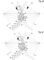
- an object B4 is shown in a front view, which is currently located in a transfer point C of a transport device 10 according to the invention, which is in the Figures 2a to 2e will be easier to recognize.
- the object B4 is an essentially cylindrical container, such as those used in the pharmaceutical industry. It goes without saying that in a variant of the device shown in the figures, it could also be used together with other object geometries.
- the object B4 is in Figure 1 supported on a base 12 and is currently in contact with a first and a second transport wheel 20, 30, which are also responsible for the propulsion of the object B4. How As will be better seen in the following figures, the object B4 is currently accommodated in recesses 22, 32 on the two star wheels 20 and 30 in the same way.
- two wall elements 40 and 50 are integrated into the base 12, which form the switch device according to the invention in the transport device shown.
- the first wall section 40 is drawn downwards into the base 12 so that its upper side is flush with the base 12, while the second wall section 50 is raised with its upper side above the base 12.
- the necessary displacement between the protruding first position in which the second wall section 50 is currently located and the retracted second position in which the first wall section 40 is currently located is brought about by individually controlled drives (not shown), for example electromechanical servomotors, which are controlled in a coordinated manner by a control device (also not shown).
- the protruding second wall section 50 represents a guide for the object B4 in the lateral direction, while the object B4 could, on the other hand, simply slide over the retracted first wall section 40.
- the wall sections 40 and 50 therefore act as a switch device for objects picked up by the transport wheels 20 and 30, i.e. objects delivered by the first star wheel 20.
- the Figures 2a to 2e A total of eight such objects B1 to B8 are shown, of which the object B4 currently located at the transfer point C is already in Figure 1 shown and described above.
- the direction of rotation of the two star wheels 20 and 30 is shown by corresponding arrows and designated by the reference symbols R1 and R2.
- the first star wheel 20 rotates clockwise and the second star wheel counterclockwise, whereby the first star wheel 20, as already mentioned, the series of objects B1 to B8 are brought to the second star wheel 30 until they are in contact with both star wheels 20 and 30 at the transfer point C.
- the already mentioned recesses 22 and 32 on the outer circumferences of the star wheels 20 and 30 are each equally spaced, namely with respect to the entire circumference of the star wheels 20 and 30 by an angle ⁇ .
- first and second wall sections 40 and 50 are provided, wherein in the Figures 2a to 2e in the first position, i.e. wall elements extended upwards from the subfloor 12, are shown hatched and in the second position, i.e. wall elements sunk into the subfloor 12, are shown only with their outlines.
- the two wall sections 40 and 50 are each made up of several parts, namely three parts each with three wall elements 42, 44, 46 or 52, 54, and 56.
- the wall sections essentially follow circular path segments which are offset outwards by half the diameter of the objects B1 to B8 compared to the outer circumference of the corresponding star wheel 20 or 30, so that the objects B1 to B8 accommodated in the recesses 22 or 32 are guided straight along the outer circumference of the corresponding star wheel 20 or 30 by the guiding effect of the wall sections 40 or 50.
- the length of the individual wall elements 42 to 46 and 52 to 56 is essentially selected in a ratio of 2:1:1 to the radius of the objects B1 to B8, whereby particularly small distances between the objects B1 to B8 and the outer circumferences of the star wheels 20 and 30 can be designed, as will become clear from the following description of a switch process.
- the figures show a device with three-part wall sections 40 and 50, It is conceivable that in a variant of an embodiment according to the invention these could also be designed in one, two or more parts.
- the object B4 which is currently located at the transfer point C, is to be transferred to the second star wheel 30.
- This transfer process is described in the Figures 2b to 2e First, as in Figure 2b shown, the respective first wall elements 42 and 52 are transferred to their respective other position, ie the wall element 42 into its first position and the wall element 52 into its second position.
- the first wall element 42 of the first wall section 40 serves as a guide surface for the object B4, while the wall elements 54 and 56 remaining in their first position continue to serve as a guide surface for the object B5 remaining on the first star wheel 20.
- the switch device After a predetermined rotation amount has been covered by the two star wheels 20 and 30, the switch device goes into the Figure 2c shown state, in which the second wall element 54 of the second wall section 50 has additionally been transferred to its second position, so that in the area of the respective second wall elements 44 and 54 there is no guide surface for the two objects B4 and B5 currently located there. Accordingly, the object B4 will continue guided solely by the first wall element 42 of the first wall section 40 and the object B5 guided solely by the third wall element 56 of the second wall section 50, while in the region of the respective second wall elements 44 and 54 opposite movements of the objects B4 and B5 are possible.
- this second wall element 44 is also transferred to its first position in order to represent a guide surface for the object B4 which is just entering its area at this moment.
- the object B5 runs out of the area of the third wall element 56 of the second wall section 50 and enters the area of a downstream guide rail 60 which begins essentially behind the transfer point C at a point at which the switching process for the objects B1 to B8 is completed.
Landscapes
- Engineering & Computer Science (AREA)
- Mechanical Engineering (AREA)
- Specific Conveyance Elements (AREA)
Description
- Die vorliegende Erfindung betrifft eine Weichenvorrichtung für einen Übergabepunkt zwischen einem ersten und einem zweiten rotierbaren Sternrad, an welchem von dem ersten Sternrad Objekte selektiv zu dem zweiten Sternrad übergebbar sind.
- Es sei darauf hingewiesen, dass in der gesamten vorliegenden Anmeldung der Begriff des "Sternrads" breit zu verstehen ist, so dass hierdurch nicht nur streng kreisförmige Transporteinheiten zu verstehen sind, sondern auch solche, deren Außenumfangsformen von einem Kreis abweichen und beispielsweise abschnittsweise abgeflacht sind oder unterschiedlich konvexe Abschnitte aufweisen. Im Extremfall können hierbei sogar vollständig geradlinige Transporteinheiten umfasst sein, die als "Räder" mit unendlichem Durchmesser aufgefasst werden können, wobei dann beispielsweise eine Übergabe von einer linearen Transporteinheit zu einer kreisförmigen Transporteinheit vorgesehen werden kann und ebenfalls von der vorliegenden Anmeldung umfasst sein soll. In jedem Fall sind außerhalb von Weichenvorrichtungen, welche dazu dienen, Objekte auf ein Sternrad zu übergeben oder von ihm zu einer anderen Transportvorrichtung zu übergeben, wenigstens in konvexen Abschnitten Vorrichtungen, wie beispielsweise Führungsschienen vorzusehen, mittels welcher die Objekte an dem entsprechenden Sternrad gehalten werden.
- Die angesprochenen Weichenvorrichtungen werden unter anderem in der Verpackungsindustrie und beispielsweise auch in der chemischen und der Pharmaindustrie eingesetzt, um Objekte je nach ihrer Ausprägung selektieren zu können, d.h. einzelne Objekte aus einer Reihe ähnlicher Objekte aussortieren zu können, beispielsweise wenn sie fehlerhaft sind oder ähnliches.
- Derartige als fehlerhaft erkannte Objekte können dann beispielsweise stromabwärts nach einer Vorrichtung, die die Fehlerhaftigkeit des jeweiligen Objektes detektiert hat, einem anderen Pfad zugeführt werden. Hierzu werden die Objekte am Außenumfang der bereits angesprochenen Sternräder geführt und von einem ersten Sternrad, von welchem sie zu einem entsprechenden Übergabepunkt angeliefert werden, dann an diesem Punkt ggf. an ein zweites Sternrad übergeben, von welchem sie auf einen anderen Pfad überführt werden, oder sie verbleiben an dem ersten Sternrad, um dann ebenfalls von dem Übergabepunkt abgeführt zu werden. Es versteht sich hierbei, dass der Begriff des "Übergabepunkts" nicht im streng geometrischen Sinne zu verstehen ist, sondern dass die Übergabe auch auf einem ausgedehnten streifenförmigen Bereich entlang der Bewegung der Objekte stattfinden kann.
- Zu diesem Zweck sind bereits verschiedene Weichenvorrichtungen aus dem Stand der Technik bekannt, beispielsweise Vakuumräder, bei denen die Objekte an dem Außenumfang der jeweiligen Sternräder mittels Vakuumgreifern gehalten werden, die dann selektiv derart geschaltet werden können, dass an dem Übergabepunkt ein entsprechendes Objekt entweder an dem ersten Vakuum-Sternrad verbleibt oder an ein zweites Vakuum-Sternrad übergeben wird, so dass das Objekt anschließend auf einem gewünschten Pfad abgeführt werden kann. Derartige vakuumbetriebene Weichenvorrichtungen arbeiten zwar zuverlässig und können auch bei einem relativ niedrigen Objektabstand an den jeweiligen Sternrädern sicher betrieben werden, sie sind allerdings nicht immer in Reinräumen oder in einem Isolator einsetzbar, da beispielsweise aus pharmazeutischer Sicht aufgrund der möglichen Kontaminationen von außen durch Komponenten wie Schläuche, Vakuumpumpen, Ventile usw. eine Verunreinigung der hochsensiblen Objekte und ihrer Inhalte eintreten könnte.
- Somit können in vielen Anwendungsbereichen für derartige gattungsgemäße Weichenvorrichtungen lediglich mechanische Weichen eingesetzt werden, wie sie beispielsweise aus der
DE 10 2013 223 977 A1 bekannt sind. In dieser Druckschrift ist eine Vorrichtung offenbart, die zwischen zwei Sternrädern eine Weichenfunktion an einem Übergabepunkt erfüllt und hierzu ein einteiliges schwenkbares Element mit einer Führung für die von den Sternrädern getragenen Objekte aufweist, das in einer Weise verschwenkbar ist, die entweder ein Verbleiben der Objekte an dem ersten Sternrad oder eine Übergabe der Objekte an das zweite Sternrad bewirkt. Das genannte Führungselement ist allerdings zur Sicherstellung einer ausreichenden Führung der Objekte relativ lang ausgebildet, um ein Verkanten der Objekte bei ihrer Übergabe zuverlässig ausschließen zu können. Hierdurch wird jedoch andererseits eine relativ hohe Trägheit der Weichenfunktion erkauft, da sich, um aufeinanderfolgende Objekte überhaupt wirkungsvoll selektieren zu können, jeweils lediglich ein einzelnes Objekt innerhalb der Führungsvorrichtung befinden darf. Somit ist durch die Länge des Führungselements automatisch ein Mindestabstand zwischen zwei Objekten an den Sternrädern festgelegt, so dass hier relativ hohe Abstände und damit ein relativ niedriger Durchsatz an Objekten pro Zeiteinheit bei einer vorgegebenen Rotationsgeschwindigkeit der Sternräder vorgesehen werden muss. Dies geht offensichtlich auf Kosten der Effizienz der Anlage, wodurch diese im Betrieb teurer wird. Des Weiteren besteht bei der Vorrichtung aus derDE 10 2013 223 977 A1 die Gefahr, dass die Schwenkbewegung des Führungselements durch eindringenden Schmutz oder beispielsweise auch Scherben von beschädigten Objekten blockiert werden kann. - Ferner ist auch aus der
JP S65 99123 A - Es ist daher die Aufgabe der vorliegenden Erfindung, eine gattungsgemäße Weichenvorrichtung bereitzustellen, die einerseits rein mechanisch arbeitet und daher auch in Umgebungen eingesetzt werden kann, in denen aufgrund der Gefahr von Kontaminierungen nicht auf vakuumbetriebene Weichen zurückgegriffen werden kann, die eine sichere Weichenfunktion bei geringeren Objektabständen und damit eine höhere Ausbringleistung des Systems ermöglicht und die zuletzt auch die Gefahr eines Blockierens eines Führungselements ausräumt, indem auf ein Schwenken eines solchen Elements verzichtet wird.
- Zur Lösung dieser Aufgabe umfasst die erfindungsgemäße Weichenvorrichtung einen Unterboden wenigstens im Bereich des Übergabepunkts zum Abstützen der von den Sternrädern transportierten Objekte, einen ersten und einen zweiten Wandabschnitt, welche im Bereich des Übergabepunkts jeweils im Wesentlichen dem Außenumfang des ersten bzw. zweiten Sternrads folgend verlaufen und in vertikaler Richtung zwischen einer ersten Position, in welcher sie sich über den Unterboden hinaus erstrecken, und einer zweiten Position, in welcher sie sich nicht über den Unterboden hinaus erstrecken, verlagerbar sind, wenigstens einen Antriebsmechanismus zum Antreiben der Verlagerung der Wandabschnitte, und eine Steuerungseinrichtung zur Ansteuerung des wenigstens einen Antriebsmechanismus, wobei der erste und der zweite Wandabschnitt durch den wenigstens einen Antriebsmechanismus jeweils einzeln vertikal verlagerbar sind.
- Durch den Verzicht auf ein schwenkendes Führungselement und die Verwendung von vertikal verlagerbaren Wandabschnitten kann einerseits der Abstand der von den Sternrädern getragenen Objekte kleiner gewählt werden und dadurch wie oben beschrieben die Ausbringleistung erhöht werden und andererseits wird die Gefahr eines Blockierens der Vorrichtung ausgeräumt, da die versenkbaren Wandabschnitte durch geeignete Spaltmaße wesentlich weniger empfindlich für das Eindringen von Schmutz und Verunreinigungen sind.
- Erfindungsgemäß sind der erste Wandabschnitt und der zweite Wandabschnitt entlang ihres Verlaufs in jeweils wenigstens zwei Wandelemente unterteilt, welche durch den wenigstens einen Antriebsmechanismus jeweils einzeln vertikal verlagerbar sind. Hierbei ist sowohl die Form als auch die Anzahl der Wandabschnitte, die durchaus auch größer als zwei sein kann, auf die Form der zu transportierenden Objekte anpassbar.
- Durch diese jeweils in Form wenigstens zweier Wandelemente ausgebildeten Wandabschnitte wird es möglich, eine zuverlässige Weichenfunktion auch für Objekte zu erreichen, die einen geringen Abstand am Außenumfang der Sternräder aufweisen.
- Dieser Vorteil der erfindungsgemäßen Weichenvorrichtung wird noch deutlicher ausgeprägt, wenn der erste und der zweite Wandabschnitt jeweils in drei Wandelemente unterteilt sind, in welchen beispielsweise das Verhältnis der Längen der drei Wandelemente des ersten und zweiten Wandabschnitts bezüglich ihres Verlaufs jeweils etwa 2:1:1 beträgt. Hierbei kann die Länge des ersten Wandelements dann insbesondere etwa gleich dem Durchmesser der von den Sternrädern zu tragenden Objekte sein.
- Um einen besonders sicheren Betrieb der erfindungsgemäßen Weichenvorrichtung hinsichtlich möglicher Verkantungen von Objekten oder auch Ablagerungen von Fremdstoffen sicherzustellen, können die Wandabschnitte in ihrer zweiten Position jeweils mit dem Unterboden ausgerichtet sein, um eine durchgehende ebene Fläche zu bilden.
- In einer möglichen Ausführungsform kann jedem der Wandelemente ein eigener Antriebsmechanismus zugeordnet sein, beispielsweise ein elektromechanischer Antrieb, insbesondere ein Stellmotor, oder beispielsweise auch ein pneumatischer Antrieb. Da die derartigen, beispielhaft erwähnten elektromechanischen Stellmotoren in letzter Zeit sehr kostengünstig geworden sind und mit geringem Aufwand hochpräzise betreibbar sind, stellen sie eine optimale Möglichkeit zum Verlagern der einzelnen Wandelemente dar. Alternativ könnten jedoch auch komplexere mechanische Anordnungen eingesetzt werden, in denen eine geringere Zahl von Antriebsmechanismen als von Wandelementen vorgesehen wird und die jeweilige Bewegung dieser Antriebsmechanismen dann durch die genannten mechanischen Mittel in koordinierte Bewegungen der einzelnen Wandelemente umgesetzt wird.
- Gemäß einem zweiten Aspekt betrifft die vorliegende Erfindung eine Transportvorrichtung für Objekte, insbesondere zylinderförmige Objekte wie Flaschen und/oder Ampullen, umfassend ein erstes und ein zweites Sternrad, welche derart angeordnet sind, dass zwischen ihnen ein Übergabepunkt gebildet ist, sowie eine erfindungsgemäße Weichenvorrichtung zur selektiven Übergabe von Objekten von dem ersten Sternrad zu dem zweiten Sternrad. Durch leichte Anpassungen der Geometrien der Sternräder und der Weichenvorrichtung, insbesondere der Wandabschnitte, können jedoch auch komplexer geformte Objekte mit der erfindungsgemäßen Vorrichtung transportiert werden.
- Hierbei kann die Steuereinrichtung betriebsmäßig mit einer Steuereinheit für die beiden Sternräder derart gekoppelt sein, dass die Überführung der Wandelemente an die Rotationsgeschwindigkeit der Sternräder angepasst oder anpassbar ist. Alternativ könnte die Steuereinheit jedoch auch mit einem Sensor zur Erfassung der Rotation der Sternräder gekoppelt sein, so dass ein autarker Betrieb der Weichenvorrichtung hinsichtlich der Steuerung der Rotation der Sternräder durchgeführt werden kann.
- Ferner kann die erfindungsgemäße Transportvorrichtung wenigstens eine Führungsschiene umfassen, welche sich in einer Verlängerung von wenigstens einem der Wandabschnitte erstreckt. Auf diese Weise kann sichergestellt werden, dass vor und/oder hinter dem Übergabepunkt die Objekte entlang ihrer vorgesehenen Bahnen weiter transportiert werden.
- Zuletzt sei noch darauf hingewiesen, dass die erfindungsgemäße Transportvorrichtung modular aufgebaut sein kann, um auf verschiedene Geometrien und Abmessungen der zu transportierenden Objekte anpassbar zu sein. Hierzu kann beispielsweise ein System, bestehend aus mehreren Paaren von Sternrädern, die jeweils auf eine Art von Objekten abgestimmt sind, sowie einer jeweiligen zugehörigen Weichenvorrichtung vorgesehen werden, die in der Anzahl ihrer Wandelemente und deren Geometrien sowie auch ihrer Ansteuerung ebenfalls auf die entsprechenden Objekte angepasst ist. Somit können dann in einem Fall, in dem der Typ der zu transportierenden Objekte im Betrieb der Anlage geändert werden soll, die Sternräder und die Weichenvorrichtung gemeinsam ersetzt werden, während weitere Komponenten wie Antriebe und Zuführ- bzw. Abführvorrichtungen für die Objekte unverändert verbleiben können.
- Weitere Merkmale und Vorteile der vorliegenden Erfindung werden aus der nachfolgenden Beschreibung einer Ausführungsform deutlich, wenn diese zusammen mit den beiliegenden Figuren betrachtet wird. Diese zeigen im Einzelnen:
- Figur 1
- eine Vorderansicht eines im Übergabepunkt einer erfindungsgemäßen Transportvorrichtung befindlichen zylinderförmigen Objekts;
- Figuren 2a bis 2e
- Draufsichten auf eine erfindungsgemäße Transportvorrichtung zu fünf aufeinanderfolgenden Zeitpunkten während einer Übergabe des Objekts aus
Figur 1 . - In
Figur 1 ist zunächst ein Objekt B4 in einer Vorderansicht gezeigt, das sich momentan in einem Übergabepunkt C einer erfindungsgemäßen Transportvorrichtung 10 befindet, der in denFiguren 2a bis 2e besser zu erkennen sein wird. Bei dem Objekt B4 handelt es sich um ein im Wesentlichen zylindrisches Behältnis, wie es beispielsweise in der Pharmaindustrie eingesetzt wird. Es versteht sich, dass in einer Variante der in den Figuren gezeigten Vorrichtung diese auch zusammen mit anderen Objektgeometrien einsetzbar wäre. - Das Objekt B4 ist in
Figur 1 auf einem Unterboden 12 abgestützt geführt und steht momentan mit einem ersten und einem zweiten Transportrad 20, 30 in Kontakt, die auch für den Vortrieb des Objekts B4 verantwortlich sind. Wie aus den nachfolgenden Figuren besser zu erkennen sein wird, ist das Objekt B4 momentan in Ausnehmungen 22, 32 an den beiden Sternrädern 20 und 30 in gleicher Weise aufgenommen. - Des Weiteren finden sich in den Unterboden 12 integriert zwei Wandelemente 40 und 50, die in der gezeigten Transportvorrichtung die erfindungsgemäße Weichenvorrichtung bilden. In dem in
Figur 1 gezeigten Zustand ist der erste Wandabschnitt 40 nach unten in den Unterboden 12 eingezogen, so dass seine Oberseite plan mit dem Unterboden 12 ausgerichtet ist, während der zweite Wandabschnitt 50 mit seiner Oberseite über den Unterboden 12 hinaus angehoben ist. Die hierzu notwendige Verlagerung zwischen der vorstehenden ersten Position, in der sich der zweite Wandabschnitt 50 momentan befindet, und der zurückgezogenen zweiten Position, in der sich der erste Wandabschnitt 40 momentan befindet, wird hierbei von (nicht gezeigten) individuell angesteuerten Antrieben, beispielsweise elektromechanischen Stellmotoren, hervorgerufen, die von einer ebenfalls nicht gezeigten Steuereinrichtung koordiniert angesteuert werden. Es ist ersichtlich, dass der vorstehende zweite Wandabschnitt 50 für das Objekt B4 eine Führung in seitlicher Richtung darstellt, während das Objekt B4 andererseits über den zurückgezogenen ersten Wandabschnitt 40 einfach hinweggleiten könnte. - Wie sich aus den
Figuren 2a bis 2e ergibt, wirken die Wandabschnitte 40 und 50 demzufolge als Weichenvorrichtung für an den Transporträdern 20 und 30 aufgenommene, also von dem ersten Sternrad 20 angelieferte Objekte. Zur Verdeutlichung sind hierzu in denFiguren 2a bis 2e insgesamt acht derartige Objekte B1 bis B8 gezeigt, von denen das momentan im Übergabepunkt C befindliche Objekt B4 bereits inFigur 1 gezeigt und weiter oben beschrieben worden war. Ferner ist in denFiguren 2a bis 2e jeweils die Drehrichtung der beiden Sternräder 20 und 30 durch entsprechende Pfeile dargestellt und mit den Bezugszeichen R1 und R2 bezeichnet. Hierbei dreht sich das erste Sternrad 20 im Uhrzeigersinn und das zweite Sternrad im Gegenuhrzeigersinn, wobei vom ersten Sternrad 20, wie bereits angesprochen, dementsprechend die Reihe von Objekten B1 bis B8 an das zweite Sternrad 30 herangeführt werden, bis sie im Übergabepunkt C mit beiden Sternrädern 20 und 30 in Kontakt stehen. Weiterhin soll darauf hingewiesen sein, dass die bereits angesprochenen Ausnehmungen 22 und 32 an den Außenumfängen der Sternräder 20 und 30 jeweils gleich beabstandet sind, nämlich hinsichtlich des gesamten Umfangs der Sternräder 20 und 30 jeweils um einen Winkel α. - Um die angesprochene Weichenfunktion, mittels welcher selektiv einzelne der Objekte B1 bis B8 von dem ersten Sternrad 20 auf das zweite Sternrad 30 übergeben werden können, auszuführen, sind die bereits angesprochenen ersten und zweiten Wandabschnitte 40 und 50 vorgesehen, wobei in den
Figuren 2a bis 2e jeweils in der ersten Position, also nach oben aus dem Unterboden 12 ausgefahrene Wandelemente schraffiert dargestellt sind und in der zweiten Position befindliche, d.h. im Unterboden 12 versenkte Wandelemente lediglich mit ihren Umrissen dargestellt sind. - Aus den
Figuren 2a bis 2e ist ferner ebenfalls zu entnehmen, dass die beiden Wandabschnitte 40 und 50 jeweils mehrteilig ausgebildet sind, nämlich jeweils dreiteilig mit drei Wandelementen 42, 44, 46 bzw. 52, 54, und 56. Hierbei folgen die Wandabschnitte im Wesentlichen Kreisbahnsegmenten, die um einen halben Durchmesser der Objekte B1 bis B8 gegenüber dem Außenumfang des entsprechenden Sternrads 20 bzw. 30 nach außen versetzt sind, so dass die in den Ausnehmungen 22 bzw. 32 aufgenommenen Objekte B1 bis B8 durch die Führungswirkung der Wandabschnitte 40 bzw. 50 gerade entlang des Außenumfangs des entsprechenden Sternrads 20 bzw. 30 geführt werden. Die Länge der einzelnen Wandelemente 42 bis 46 bzw. 52 bis 56 ist jeweils im Wesentlichen im Verhältnis 2:1:1 zum Radius der Objekte B1 bis B8 gewählt, wodurch sich besonders geringe Abstände der Objekte B1 bis B8 an den Außenumfängen der Sternräder 20 und 30 auslegen lassen, wie aus der nachfolgenden Beschreibung eines Weichenvorgangs deutlich werden wird. Wenngleich in den Figuren eine Vorrichtung mit jeweils dreiteiligen Wandabschnitten 40 und 50 gezeigt ist, so versteht sich, dass in einer Variante einer erfindungsgemäßen Ausführungsform diese auch jeweils ein-, zwei- oder mehrteilig ausgebildet sein könnten. - Beginnend bei der
Figur 2a lässt sich erkennen, dass die Objekte B5 bis B8 bereits durch den Übergabepunkt C hindurchgelaufen sind, ohne von dem ersten Sternrad 20 an das zweite Sternrad 30 übergeben worden zu sein. Zu diesem Zweck waren sämtliche Wandelemente 52 bis 56 des zweiten Wandabschnitts 50 in ihrer jeweiligen ersten Position, d.h. sie erstreckten sich aus dem Unterboden 12 nach oben heraus und bildeten eine Führungsfläche zum Führen der Objekte B5 bis B8 entlang der Krümmung des ersten Sternrads 20, während die Wandelemente 42 bis 46 des ersten Wandabschnitts 40 in ihrer zweiten Position im Unterboden 12 versenkt waren, so dass die Objekte B5 bis B8 über sie hinweg gleiten konnten. - Nun soll jedoch das Objekt B4, das sich momentan im Übergabepunkt C befindet, auf das zweite Sternrad 30 übergeben werden. Dieser Übergabeprozess ist in den
Figuren 2b bis 2e dargestellt. Hierzu werden zunächst, wie inFigur 2b gezeigt, die jeweiligen ersten Wandelemente 42 und 52 in ihre jeweils andere Position überführt, d.h. das Wandelement 42 in seine erste Position und das Wandelement 52 in seine zweite Position. Somit dient das erste Wandelement 42 des ersten Wandabschnitts 40 als Führungsfläche für das Objekt B4, während die weiterhin in ihrer ersten Position verbleibenden Wandelemente 54 und 56 unverändert als Führungsfläche für das am ersten Sternrad 20 verbleibende Objekt B5 dienen. - Anschließend geht nach einem Überstreichen eines vorbestimmten Rotationsbetrags durch die beiden Sternräder 20 und 30 die Weichenvorrichtung in den in
Figur 2c gezeigten Zustand über, in dem zusätzlich das zweite Wandelement 54 des zweiten Wandabschnitts 50 in seine zweite Position überführt worden ist, so dass im Bereich der jeweiligen zweiten Wandelemente 44 und 54 keine Führungsfläche für die beiden momentan dort befindlichen Objekte B4 und B5 vorliegt. Dementsprechend wird das Objekt B4 weiterhin allein von dem ersten Wandelement 42 des ersten Wandabschnitts 40 geführt und das Objekt B5 allein vom dritten Wandelement 56 des zweiten Wandabschnitts 50 geführt, während im Bereich der jeweiligen zweiten Wandelemente 44 und 54 entgegengesetzte Bewegungen der Objekte B4 und B5 möglich sind. - Anschließend, nachdem das Objekt B5 aus dem Bereich des zweiten Wandelements 44 des ersten Wandabschnitts 40 herausgelaufen ist, wird dieses zweite Wandelement 44 ebenfalls in seine erste Position überführt, um eine Führungsfläche für das gerade in diesem Moment in seinen Bereich einlaufende Objekt B4 darzustellen. Im Wesentlichen gleichzeitig läuft das Objekt B5 aus dem Bereich des dritten Wandelements 56 des zweiten Wandabschnitts 50 heraus und tritt in den Bereich einer nachgelagerten Führungsschiene 60 ein, die im Wesentlichen hinter dem Übergabepunkt C an einer Stelle beginnt, an der der Weichenvorgang für die Objekte B1 bis B8 abgeschlossen ist.
- Da somit eine Führung durch das dritte Wandelement 56 nicht mehr notwendig ist, kann dieses ebenfalls in seinen zweiten Zustand überführt werden, so dass, wie in
Figur 2e gezeigt, das Objekt B4 darüber hinweglaufen kann. Nachdem nun das Objekt B5 allein von der Führungsschiene 60 geführt wird, kann zuletzt das dritte Wandelement 46 des zweiten Wandabschnitts 40 in seine erste Position überführt werden, um das Objekt B4 endgültig auf das zweite Sternrad 30 zu übergeben. Das auf dieses zweite Sternrad 30 übergebene Objekt B4 wird anschließend von der Führungsschiene 60 weitergeführt werden, bis es schließlich an einer späteren Position von dem zweiten Sternrad 30 entnommen und weitertransportiert werden kann. - Derweil ist ein weiteres nachfolgendes Objekt B3 in den Übergabepunkt C eingetreten, das wiederum an dem ersten Sternrad 20 verbleiben soll, weswegen die beiden ersten Wandelemente 42 und 52 jeweils wieder in ihre zweite bzw. erste Position überführt worden sind, um das Objekt B3 entlang des ersten Sternrads 20 zu führen.
- Wie sich aus den
Figuren 2a bis 2e ergibt, kann durch das Vorsehen und den koordinierten Betrieb der jeweils dreiteiligen Wandabschnitte 20 und 30 ein sehr geringer Abstand zwischen den einzelnen Objekten B1 und B8 erzielt werden, während das zuverlässige Durchführen der Weichenfunktion durch die Weichenvorrichtung dennoch sichergestellt ist.
Claims (8)
- Weichenvorrichtung für einen Übergabepunkt (C) zwischen einem ersten und einem zweiten rotierbaren Sternrad (20, 30), an welchem von dem ersten Sternrad (20) Objekte (B1 - B8) selektiv zu dem zweiten Sternrad (30) übergebbar sind, umfassend:- einen Unterboden (12) wenigstens im Bereich des Übergabepunkts (C) zum Abstützen der von den Sternrädern transportierten Objekte (B1 - B8);- einen ersten und einen zweiten Wandabschnitt (40, 50), welche im Bereich des Übergabepunkts (C) jeweils im Wesentlichen dem Außenumfang des ersten bzw. zweiten Sternrads (20, 30) folgend verlaufen und in vertikaler Richtung zwischen einer ersten Position, in welcher sie sich über den Unterboden (12) hinaus erstrecken, und einer zweiten Position, in welcher sie sich nicht über den Unterboden (12) hinaus erstrecken, verlagerbar sind;- wenigstens einen Antriebsmechanismus zum Antreiben der Verlagerung der Wandabschnitte (40, 50); und- eine Steuerungseinrichtung zur Ansteuerung des wenigstens einen Antriebsmechanismus;wobei der erste und der zweite Wandabschnitt (40, 50) durch den wenigstens einen Antriebsmechanismus jeweils einzeln vertikal verlagerbar sind.dadurch gekennzeichnet, dassder erste und der zweite Wandabschnitt (40, 50) entlang ihres Verlaufs in jeweils wenigstens zwei Wandabschnitte (42, 44, 46, 52, 54, 56) unterteilt sind, welche durch den wenigstens einen Antriebsmechanismus jeweils einzeln vertikal verlagerbar sind.
- Weichenvorrichtung nach Anspruch 1, dadurch gekennzeichnet, dass der erste und der zweite Wandabschnitt (40, 50) jeweils in drei Wandelemente (42, 44, 46, 52, 54, 56) unterteilt sind.
- Weichenvorrichtung nach Anspruch 2, dadurch gekennzeichnet, dass das Verhältnis der Längen der drei Wandelemente (42, 44, 46, 52, 54, 56) des ersten und zweiten Wandabschnitts (40, 50) bezüglich ihres Verlaufs etwa 2:1:1 beträgt.
- Weichenvorrichtung nach einem der vorhergehenden Ansprüche, dadurch gekennzeichnet, dass die Wandabschnitte (40, 50) in ihrer zweiten Position jeweils mit dem Unterboden (12) ausgerichtet sind, um eine durchgehende ebene Fläche zu bilden.
- Weichenvorrichtung nach einem der vorhergehenden Ansprüche, dadurch gekennzeichnet, dass jedem der Wandelemente (42, 44, 46, 52, 54, 56) ein eigener Antriebsmechanismus zugeordnet ist, beispielsweise ein elektromechanischer Stellmotor.
- Transportvorrichtung für Objekte (B1 - B8), insbesondere zylinderförmige Objekte (B1 - B8) wie Flaschen und/oder Ampullen, umfassend ein erstes und ein zweites Sternrad (20, 30), welche derart angeordnet sind, dass zwischen ihnen ein Übergabepunkt (C) gebildet ist, sowie eine Weichenvorrichtung nach einem der vorhergehenden Ansprüche zur selektiven Übergabe von Objekten (B1 - B8) von dem ersten Sternrad (20) zu dem zweiten Sternrad (30).
- Transportvorrichtung nach Anspruch 6, dadurch gekennzeichnet, dass die Steuereinrichtung betriebsmäßig mit einer Steuereinheit für die beiden Sternräder (20, 30) derart gekoppelt ist, dass die Überführung der Wandelemente (42, 44, 46, 52, 54, 56) an die Rotationsgeschwindigkeit der Sternräder (20, 30) angepasst oder anpassbar ist.
- Transportvorrichtung nach einem der Ansprüche 6 oder 7, dadurch gekennzeichnet, dass sie ferner wenigstens eine Führungsschiene (60) umfasst, welche sich in einer Verlängerung von wenigstens einem der Wandabschnitte (40, 50) erstreckt.
Applications Claiming Priority (2)
| Application Number | Priority Date | Filing Date | Title |
|---|---|---|---|
| DE102018208956.6A DE102018208956A1 (de) | 2018-06-06 | 2018-06-06 | Weichenvorrichtung |
| PCT/EP2019/062571 WO2019233723A1 (de) | 2018-06-06 | 2019-05-16 | Weichenvorrichtung |
Publications (2)
| Publication Number | Publication Date |
|---|---|
| EP3802383A1 EP3802383A1 (de) | 2021-04-14 |
| EP3802383B1 true EP3802383B1 (de) | 2024-05-15 |
Family
ID=66655309
Family Applications (1)
| Application Number | Title | Priority Date | Filing Date |
|---|---|---|---|
| EP19726593.7A Active EP3802383B1 (de) | 2018-06-06 | 2019-05-16 | Weichenvorrichtung |
Country Status (6)
| Country | Link |
|---|---|
| US (1) | US11292673B2 (de) |
| EP (1) | EP3802383B1 (de) |
| CN (1) | CN111372877B (de) |
| DE (1) | DE102018208956A1 (de) |
| ES (1) | ES2988055T3 (de) |
| WO (1) | WO2019233723A1 (de) |
Families Citing this family (2)
| Publication number | Priority date | Publication date | Assignee | Title |
|---|---|---|---|---|
| WO2020182904A1 (de) | 2019-03-14 | 2020-09-17 | Fresenius Kabi Austria Gmbh | Anlage sowie verfahren zum sortieren von gebinden |
| CN118358973B (zh) * | 2024-06-20 | 2024-09-10 | 福建太平洋制药有限公司 | 一种吸入型制剂生产用理瓶设备及方法 |
Family Cites Families (23)
| Publication number | Priority date | Publication date | Assignee | Title |
|---|---|---|---|---|
| US2269422A (en) * | 1939-12-30 | 1942-01-13 | Ayars Machine Co | Can delivering mechanism |
| US2500465A (en) * | 1945-08-27 | 1950-03-14 | Meyer Geo J Mfg Co | Filling machine drive |
| DE1084640B (de) * | 1956-10-05 | 1960-06-30 | Crown Cork & Seal Co | Vorrichtung zum Aufteilen von auf einem ersten Foerderer angelieferten Behaeltern auf zwei Weiterfoerderer |
| DE2853696A1 (de) * | 1978-12-13 | 1980-06-26 | Holstein & Kappert Maschf | Vorrichtung zum transportieren von behaeltern |
| JPS5699123A (en) | 1980-01-07 | 1981-08-10 | Takeda Chem Ind Ltd | Distributing equipment |
| DE3141364C2 (de) * | 1981-10-17 | 1984-12-20 | Krones Ag Hermann Kronseder Maschinenfabrik, 8402 Neutraubling | Vorrichtung zum Verteilen von aufrechtstehenden Gefäßen |
| JPS6186308A (ja) * | 1984-10-03 | 1986-05-01 | Ezaki Glyco Kk | 材料供給の多列化装置 |
| US5441063A (en) * | 1993-07-13 | 1995-08-15 | Pepsico, Inc. | High speed bottle washing machine |
| US6257820B1 (en) * | 1999-02-05 | 2001-07-10 | Fmc Corporation | Atmospheric rotary feed and discharge turret valve and method |
| US6213309B1 (en) * | 1999-04-30 | 2001-04-10 | B & H Manufacturing Company, Inc. | Turret feed control apparatus for sorting and distributing articles in a process system |
| FR2800361B1 (fr) * | 1999-10-29 | 2001-12-07 | Serac Group | Installation de transfert de recipients comportant un organe de deviation |
| DE10345317A1 (de) * | 2003-09-30 | 2005-04-14 | Khs Maschinen- Und Anlagenbau Ag | Überleitvorrichtung für Behälterbehandlungsmaschinen |
| DE102006013844A1 (de) * | 2006-03-25 | 2007-10-11 | Khs Ag | Vakuumtrommel sowie Etikettiermaschine mit einer solchen Trommel für die Rundum-Etikettierung von Flaschen oder dergleichen Behälter |
| DE102011115512A1 (de) * | 2011-10-11 | 2013-04-11 | Khs Gmbh | Transferstern |
| ITTO20111145A1 (it) * | 2011-12-13 | 2013-06-14 | Sidel Spa Con Socio Unico | Dispositivo convogliatore per articoli ed impianto di trattamento di tali articoli comprendente il suddetto dispositivo convogliatore |
| FR2993259B1 (fr) * | 2012-07-13 | 2014-08-29 | Sidel Participations | Dispositif d'augmentation de pas pour transfert positif et individuel d'objets |
| ITVR20130155A1 (it) * | 2013-07-04 | 2015-01-05 | Pe Labellers Spa | Dispositivo di alimentazione ordinata di macchina confezionatrice di bottiglie e simili |
| DE102013223977A1 (de) | 2013-11-25 | 2015-05-28 | Robert Bosch Gmbh | Transportvorrichtung mit Pfadumschaltung |
| FR3023273B1 (fr) * | 2014-07-02 | 2016-08-12 | Serac Group | Installation de transport de recipients |
| JP6424511B2 (ja) * | 2014-08-08 | 2018-11-21 | 東洋製罐株式会社 | 物品の搬送方法及びその装置 |
| JP6716858B2 (ja) * | 2015-01-15 | 2020-07-01 | 東洋製罐株式会社 | 缶体の充填巻締装置及び充填巻締方法 |
| EP3144234A1 (de) * | 2015-09-21 | 2017-03-22 | Sidel Participations | Vorrichtung zum herstellen von flaschen aus kunststoff |
| DE102016200150B4 (de) * | 2016-01-08 | 2026-07-02 | Syntegon Technology Gmbh | Umlenkvorrichtung zum Umlenken von Behältnissen |
-
2018
- 2018-06-06 DE DE102018208956.6A patent/DE102018208956A1/de not_active Withdrawn
-
2019
- 2019-05-16 EP EP19726593.7A patent/EP3802383B1/de active Active
- 2019-05-16 CN CN201980004609.7A patent/CN111372877B/zh active Active
- 2019-05-16 WO PCT/EP2019/062571 patent/WO2019233723A1/de not_active Ceased
- 2019-05-16 US US16/967,021 patent/US11292673B2/en active Active
- 2019-05-16 ES ES19726593T patent/ES2988055T3/es active Active
Also Published As
| Publication number | Publication date |
|---|---|
| US11292673B2 (en) | 2022-04-05 |
| CN111372877A (zh) | 2020-07-03 |
| EP3802383A1 (de) | 2021-04-14 |
| WO2019233723A1 (de) | 2019-12-12 |
| DE102018208956A1 (de) | 2019-12-12 |
| ES2988055T3 (es) | 2024-11-19 |
| US20210362958A1 (en) | 2021-11-25 |
| CN111372877B (zh) | 2022-05-17 |
Similar Documents
| Publication | Publication Date | Title |
|---|---|---|
| EP2420344B1 (de) | Verfahren und Vorrichtung zum Herstellen eines Konturschnitts in einem Blechband | |
| EP2174304B1 (de) | Drei-wege-weiche zum umleiten von blattförmigen medien | |
| DE1460125C3 (de) | Vorrichtung zum Schneiden von Textilien | |
| EP1591693A2 (de) | Verfahren und Vorrichtung zum Speichern einer Schubkette | |
| DE2614422A1 (de) | Vorrichtung zur fertigung von gegenstaenden wie zweistueckige dosenkoerper | |
| DE20002411U1 (de) | Vorrichtung zum Ablenken von Gegenständen, insbesondere Behältern, von einer Bewegungsbahn | |
| EP3057891B1 (de) | Ausleitvorrichtung zum ausleiten von behältern | |
| DE4232497C2 (de) | Vorrichtung zur Positionierung einer Karosserie auf einem Förderer | |
| WO2012062577A1 (de) | Fördereinrichtung zum fördern von werkstücken | |
| EP3802383A1 (de) | Weichenvorrichtung | |
| DE2236188C3 (de) | Fördervorrichtung | |
| EP3793920B1 (de) | Weichenvorrichtung | |
| EP3210916B1 (de) | Stauförderer mit einer vereinzelungsvorrichtung und verfahren zum vereinzeln | |
| DE69507927T2 (de) | Vorrichtung zur Verschieben eines Produktes | |
| DE102018007909A1 (de) | Transportsystem zum Transportieren und/oder Positionieren von Objekten entlang einer Transportstrecke sowie Transportkörper für ein solches Transportsystem | |
| EP3829793B1 (de) | Verfahren zum betreiben einer biegepresse | |
| DE602004004205T3 (de) | Automatisches System zum Sortieren und Palettieren von Artikeln | |
| DE19829176A1 (de) | Einrichtung an einer Verpackungsmaschine | |
| DE3034469A1 (de) | Transportvorrichtung fuer werkstuecke | |
| DE102005002670A1 (de) | Verfahren zur Bearbeitung von Werkstücken mittels Laserstrahlung | |
| EP2030725B1 (de) | Vorrichtung und Verfahren zum Ausrichten von Werkstücken | |
| DE2939089A1 (de) | Vorrichtung zum sietlichen verschieben von gebaeckstuecken, insbesondere auf einem transportband | |
| EP0814922B1 (de) | Anlage zum abschneiden mehrerer drahtlängen von einem drahtmaterialstrang | |
| DE8908551U1 (de) | Aufbewahrungsvorrichtung für Werkstücke o.dgl. Gegenstände | |
| DE10051217C2 (de) | Fördersystem zum rollenden Transport zumindest bereichsweise kreiszylindrischer Werkstücke |
Legal Events
| Date | Code | Title | Description |
|---|---|---|---|
| STAA | Information on the status of an ep patent application or granted ep patent |
Free format text: STATUS: THE INTERNATIONAL PUBLICATION HAS BEEN MADE |
|
| PUAI | Public reference made under article 153(3) epc to a published international application that has entered the european phase |
Free format text: ORIGINAL CODE: 0009012 |
|
| STAA | Information on the status of an ep patent application or granted ep patent |
Free format text: STATUS: REQUEST FOR EXAMINATION WAS MADE |
|
| 17P | Request for examination filed |
Effective date: 20201201 |
|
| AK | Designated contracting states |
Kind code of ref document: A1 Designated state(s): AL AT BE BG CH CY CZ DE DK EE ES FI FR GB GR HR HU IE IS IT LI LT LU LV MC MK MT NL NO PL PT RO RS SE SI SK SM TR |
|
| AX | Request for extension of the european patent |
Extension state: BA ME |
|
| DAV | Request for validation of the european patent (deleted) | ||
| DAX | Request for extension of the european patent (deleted) | ||
| RAP3 | Party data changed (applicant data changed or rights of an application transferred) |
Owner name: BAUSCH + STROEBEL SE + CO. KG |
|
| STAA | Information on the status of an ep patent application or granted ep patent |
Free format text: STATUS: EXAMINATION IS IN PROGRESS |
|
| 17Q | First examination report despatched |
Effective date: 20230206 |
|
| GRAP | Despatch of communication of intention to grant a patent |
Free format text: ORIGINAL CODE: EPIDOSNIGR1 |
|
| STAA | Information on the status of an ep patent application or granted ep patent |
Free format text: STATUS: GRANT OF PATENT IS INTENDED |
|
| INTG | Intention to grant announced |
Effective date: 20231205 |
|
| P01 | Opt-out of the competence of the unified patent court (upc) registered |
Effective date: 20240205 |
|
| GRAS | Grant fee paid |
Free format text: ORIGINAL CODE: EPIDOSNIGR3 |
|
| GRAA | (expected) grant |
Free format text: ORIGINAL CODE: 0009210 |
|
| STAA | Information on the status of an ep patent application or granted ep patent |
Free format text: STATUS: THE PATENT HAS BEEN GRANTED |
|
| AK | Designated contracting states |
Kind code of ref document: B1 Designated state(s): AL AT BE BG CH CY CZ DE DK EE ES FI FR GB GR HR HU IE IS IT LI LT LU LV MC MK MT NL NO PL PT RO RS SE SI SK SM TR |
|
| REG | Reference to a national code |
Ref country code: CH Ref legal event code: EP |
|
| REG | Reference to a national code |
Ref country code: DE Ref legal event code: R096 Ref document number: 502019011276 Country of ref document: DE |
|
| REG | Reference to a national code |
Ref country code: IE Ref legal event code: FG4D Free format text: LANGUAGE OF EP DOCUMENT: GERMAN |
|
| REG | Reference to a national code |
Ref country code: LT Ref legal event code: MG9D |
|
| REG | Reference to a national code |
Ref country code: NL Ref legal event code: MP Effective date: 20240515 |
|
| PG25 | Lapsed in a contracting state [announced via postgrant information from national office to epo] |
Ref country code: IS Free format text: LAPSE BECAUSE OF FAILURE TO SUBMIT A TRANSLATION OF THE DESCRIPTION OR TO PAY THE FEE WITHIN THE PRESCRIBED TIME-LIMIT Effective date: 20240915 |
|
| PG25 | Lapsed in a contracting state [announced via postgrant information from national office to epo] |
Ref country code: BG Free format text: LAPSE BECAUSE OF FAILURE TO SUBMIT A TRANSLATION OF THE DESCRIPTION OR TO PAY THE FEE WITHIN THE PRESCRIBED TIME-LIMIT Effective date: 20240515 |
|
| PG25 | Lapsed in a contracting state [announced via postgrant information from national office to epo] |
Ref country code: HR Free format text: LAPSE BECAUSE OF FAILURE TO SUBMIT A TRANSLATION OF THE DESCRIPTION OR TO PAY THE FEE WITHIN THE PRESCRIBED TIME-LIMIT Effective date: 20240515 Ref country code: FI Free format text: LAPSE BECAUSE OF FAILURE TO SUBMIT A TRANSLATION OF THE DESCRIPTION OR TO PAY THE FEE WITHIN THE PRESCRIBED TIME-LIMIT Effective date: 20240515 |
|
| PG25 | Lapsed in a contracting state [announced via postgrant information from national office to epo] |
Ref country code: GR Free format text: LAPSE BECAUSE OF FAILURE TO SUBMIT A TRANSLATION OF THE DESCRIPTION OR TO PAY THE FEE WITHIN THE PRESCRIBED TIME-LIMIT Effective date: 20240816 |
|
| PG25 | Lapsed in a contracting state [announced via postgrant information from national office to epo] |
Ref country code: PT Free format text: LAPSE BECAUSE OF FAILURE TO SUBMIT A TRANSLATION OF THE DESCRIPTION OR TO PAY THE FEE WITHIN THE PRESCRIBED TIME-LIMIT Effective date: 20240916 |
|
| PG25 | Lapsed in a contracting state [announced via postgrant information from national office to epo] |
Ref country code: NL Free format text: LAPSE BECAUSE OF FAILURE TO SUBMIT A TRANSLATION OF THE DESCRIPTION OR TO PAY THE FEE WITHIN THE PRESCRIBED TIME-LIMIT Effective date: 20240515 |
|
| PG25 | Lapsed in a contracting state [announced via postgrant information from national office to epo] |
Ref country code: PL Free format text: LAPSE BECAUSE OF FAILURE TO SUBMIT A TRANSLATION OF THE DESCRIPTION OR TO PAY THE FEE WITHIN THE PRESCRIBED TIME-LIMIT Effective date: 20240515 |
|
| PG25 | Lapsed in a contracting state [announced via postgrant information from national office to epo] |
Ref country code: LV Free format text: LAPSE BECAUSE OF FAILURE TO SUBMIT A TRANSLATION OF THE DESCRIPTION OR TO PAY THE FEE WITHIN THE PRESCRIBED TIME-LIMIT Effective date: 20240515 |
|
| PG25 | Lapsed in a contracting state [announced via postgrant information from national office to epo] |
Ref country code: PT Free format text: LAPSE BECAUSE OF FAILURE TO SUBMIT A TRANSLATION OF THE DESCRIPTION OR TO PAY THE FEE WITHIN THE PRESCRIBED TIME-LIMIT Effective date: 20240916 Ref country code: PL Free format text: LAPSE BECAUSE OF FAILURE TO SUBMIT A TRANSLATION OF THE DESCRIPTION OR TO PAY THE FEE WITHIN THE PRESCRIBED TIME-LIMIT Effective date: 20240515 Ref country code: NO Free format text: LAPSE BECAUSE OF FAILURE TO SUBMIT A TRANSLATION OF THE DESCRIPTION OR TO PAY THE FEE WITHIN THE PRESCRIBED TIME-LIMIT Effective date: 20240815 Ref country code: NL Free format text: LAPSE BECAUSE OF FAILURE TO SUBMIT A TRANSLATION OF THE DESCRIPTION OR TO PAY THE FEE WITHIN THE PRESCRIBED TIME-LIMIT Effective date: 20240515 Ref country code: LV Free format text: LAPSE BECAUSE OF FAILURE TO SUBMIT A TRANSLATION OF THE DESCRIPTION OR TO PAY THE FEE WITHIN THE PRESCRIBED TIME-LIMIT Effective date: 20240515 Ref country code: IS Free format text: LAPSE BECAUSE OF FAILURE TO SUBMIT A TRANSLATION OF THE DESCRIPTION OR TO PAY THE FEE WITHIN THE PRESCRIBED TIME-LIMIT Effective date: 20240915 Ref country code: HR Free format text: LAPSE BECAUSE OF FAILURE TO SUBMIT A TRANSLATION OF THE DESCRIPTION OR TO PAY THE FEE WITHIN THE PRESCRIBED TIME-LIMIT Effective date: 20240515 Ref country code: GR Free format text: LAPSE BECAUSE OF FAILURE TO SUBMIT A TRANSLATION OF THE DESCRIPTION OR TO PAY THE FEE WITHIN THE PRESCRIBED TIME-LIMIT Effective date: 20240816 Ref country code: FI Free format text: LAPSE BECAUSE OF FAILURE TO SUBMIT A TRANSLATION OF THE DESCRIPTION OR TO PAY THE FEE WITHIN THE PRESCRIBED TIME-LIMIT Effective date: 20240515 Ref country code: BG Free format text: LAPSE BECAUSE OF FAILURE TO SUBMIT A TRANSLATION OF THE DESCRIPTION OR TO PAY THE FEE WITHIN THE PRESCRIBED TIME-LIMIT Effective date: 20240515 Ref country code: RS Free format text: LAPSE BECAUSE OF FAILURE TO SUBMIT A TRANSLATION OF THE DESCRIPTION OR TO PAY THE FEE WITHIN THE PRESCRIBED TIME-LIMIT Effective date: 20240815 |
|
| REG | Reference to a national code |
Ref country code: ES Ref legal event code: FG2A Ref document number: 2988055 Country of ref document: ES Kind code of ref document: T3 Effective date: 20241119 |
|
| REG | Reference to a national code |
Ref country code: CH Ref legal event code: PL |
|
| PG25 | Lapsed in a contracting state [announced via postgrant information from national office to epo] |
Ref country code: DK Free format text: LAPSE BECAUSE OF FAILURE TO SUBMIT A TRANSLATION OF THE DESCRIPTION OR TO PAY THE FEE WITHIN THE PRESCRIBED TIME-LIMIT Effective date: 20240515 |
|
| PG25 | Lapsed in a contracting state [announced via postgrant information from national office to epo] |
Ref country code: LU Free format text: LAPSE BECAUSE OF NON-PAYMENT OF DUE FEES Effective date: 20240516 |
|
| PG25 | Lapsed in a contracting state [announced via postgrant information from national office to epo] |
Ref country code: EE Free format text: LAPSE BECAUSE OF FAILURE TO SUBMIT A TRANSLATION OF THE DESCRIPTION OR TO PAY THE FEE WITHIN THE PRESCRIBED TIME-LIMIT Effective date: 20240515 |
|
| PG25 | Lapsed in a contracting state [announced via postgrant information from national office to epo] |
Ref country code: CZ Free format text: LAPSE BECAUSE OF FAILURE TO SUBMIT A TRANSLATION OF THE DESCRIPTION OR TO PAY THE FEE WITHIN THE PRESCRIBED TIME-LIMIT Effective date: 20240515 |
|
| PG25 | Lapsed in a contracting state [announced via postgrant information from national office to epo] |
Ref country code: SK Free format text: LAPSE BECAUSE OF FAILURE TO SUBMIT A TRANSLATION OF THE DESCRIPTION OR TO PAY THE FEE WITHIN THE PRESCRIBED TIME-LIMIT Effective date: 20240515 Ref country code: RO Free format text: LAPSE BECAUSE OF FAILURE TO SUBMIT A TRANSLATION OF THE DESCRIPTION OR TO PAY THE FEE WITHIN THE PRESCRIBED TIME-LIMIT Effective date: 20240515 |
|
| PG25 | Lapsed in a contracting state [announced via postgrant information from national office to epo] |
Ref country code: SM Free format text: LAPSE BECAUSE OF FAILURE TO SUBMIT A TRANSLATION OF THE DESCRIPTION OR TO PAY THE FEE WITHIN THE PRESCRIBED TIME-LIMIT Effective date: 20240515 |
|
| PG25 | Lapsed in a contracting state [announced via postgrant information from national office to epo] |
Ref country code: SM Free format text: LAPSE BECAUSE OF FAILURE TO SUBMIT A TRANSLATION OF THE DESCRIPTION OR TO PAY THE FEE WITHIN THE PRESCRIBED TIME-LIMIT Effective date: 20240515 Ref country code: SK Free format text: LAPSE BECAUSE OF FAILURE TO SUBMIT A TRANSLATION OF THE DESCRIPTION OR TO PAY THE FEE WITHIN THE PRESCRIBED TIME-LIMIT Effective date: 20240515 Ref country code: RO Free format text: LAPSE BECAUSE OF FAILURE TO SUBMIT A TRANSLATION OF THE DESCRIPTION OR TO PAY THE FEE WITHIN THE PRESCRIBED TIME-LIMIT Effective date: 20240515 Ref country code: LU Free format text: LAPSE BECAUSE OF NON-PAYMENT OF DUE FEES Effective date: 20240516 Ref country code: EE Free format text: LAPSE BECAUSE OF FAILURE TO SUBMIT A TRANSLATION OF THE DESCRIPTION OR TO PAY THE FEE WITHIN THE PRESCRIBED TIME-LIMIT Effective date: 20240515 Ref country code: DK Free format text: LAPSE BECAUSE OF FAILURE TO SUBMIT A TRANSLATION OF THE DESCRIPTION OR TO PAY THE FEE WITHIN THE PRESCRIBED TIME-LIMIT Effective date: 20240515 Ref country code: CZ Free format text: LAPSE BECAUSE OF FAILURE TO SUBMIT A TRANSLATION OF THE DESCRIPTION OR TO PAY THE FEE WITHIN THE PRESCRIBED TIME-LIMIT Effective date: 20240515 Ref country code: CH Free format text: LAPSE BECAUSE OF NON-PAYMENT OF DUE FEES Effective date: 20240531 |
|
| PG25 | Lapsed in a contracting state [announced via postgrant information from national office to epo] |
Ref country code: MC Free format text: LAPSE BECAUSE OF FAILURE TO SUBMIT A TRANSLATION OF THE DESCRIPTION OR TO PAY THE FEE WITHIN THE PRESCRIBED TIME-LIMIT Effective date: 20240515 |
|
| REG | Reference to a national code |
Ref country code: DE Ref legal event code: R097 Ref document number: 502019011276 Country of ref document: DE |
|
| REG | Reference to a national code |
Ref country code: BE Ref legal event code: MM Effective date: 20240531 |
|
| PLBE | No opposition filed within time limit |
Free format text: ORIGINAL CODE: 0009261 |
|
| STAA | Information on the status of an ep patent application or granted ep patent |
Free format text: STATUS: NO OPPOSITION FILED WITHIN TIME LIMIT |
|
| PG25 | Lapsed in a contracting state [announced via postgrant information from national office to epo] |
Ref country code: IE Free format text: LAPSE BECAUSE OF NON-PAYMENT OF DUE FEES Effective date: 20240516 |
|
| 26N | No opposition filed |
Effective date: 20250218 |
|
| GBPC | Gb: european patent ceased through non-payment of renewal fee |
Effective date: 20240815 |
|
| PG25 | Lapsed in a contracting state [announced via postgrant information from national office to epo] |
Ref country code: SI Free format text: LAPSE BECAUSE OF FAILURE TO SUBMIT A TRANSLATION OF THE DESCRIPTION OR TO PAY THE FEE WITHIN THE PRESCRIBED TIME-LIMIT Effective date: 20240515 Ref country code: BE Free format text: LAPSE BECAUSE OF NON-PAYMENT OF DUE FEES Effective date: 20240531 |
|
| PG25 | Lapsed in a contracting state [announced via postgrant information from national office to epo] |
Ref country code: FR Free format text: LAPSE BECAUSE OF NON-PAYMENT OF DUE FEES Effective date: 20240715 |
|
| PG25 | Lapsed in a contracting state [announced via postgrant information from national office to epo] |
Ref country code: GB Free format text: LAPSE BECAUSE OF NON-PAYMENT OF DUE FEES Effective date: 20240815 |
|
| REG | Reference to a national code |
Ref country code: AT Ref legal event code: MM01 Ref document number: 1686791 Country of ref document: AT Kind code of ref document: T Effective date: 20240516 |
|
| PG25 | Lapsed in a contracting state [announced via postgrant information from national office to epo] |
Ref country code: AT Free format text: LAPSE BECAUSE OF NON-PAYMENT OF DUE FEES Effective date: 20240516 |
|
| PG25 | Lapsed in a contracting state [announced via postgrant information from national office to epo] |
Ref country code: CY Free format text: LAPSE BECAUSE OF FAILURE TO SUBMIT A TRANSLATION OF THE DESCRIPTION OR TO PAY THE FEE WITHIN THE PRESCRIBED TIME-LIMIT; INVALID AB INITIO Effective date: 20190516 |
|
| PG25 | Lapsed in a contracting state [announced via postgrant information from national office to epo] |
Ref country code: HU Free format text: LAPSE BECAUSE OF FAILURE TO SUBMIT A TRANSLATION OF THE DESCRIPTION OR TO PAY THE FEE WITHIN THE PRESCRIBED TIME-LIMIT; INVALID AB INITIO Effective date: 20190516 |
|
| PG25 | Lapsed in a contracting state [announced via postgrant information from national office to epo] |
Ref country code: SE Free format text: LAPSE BECAUSE OF FAILURE TO SUBMIT A TRANSLATION OF THE DESCRIPTION OR TO PAY THE FEE WITHIN THE PRESCRIBED TIME-LIMIT Effective date: 20240515 |
|
| PGFP | Annual fee paid to national office [announced via postgrant information from national office to epo] |
Ref country code: ES Payment date: 20250630 Year of fee payment: 7 |
|
| PG25 | Lapsed in a contracting state [announced via postgrant information from national office to epo] |
Ref country code: TR Free format text: LAPSE BECAUSE OF FAILURE TO SUBMIT A TRANSLATION OF THE DESCRIPTION OR TO PAY THE FEE WITHIN THE PRESCRIBED TIME-LIMIT Effective date: 20240515 |
|
| PG25 | Lapsed in a contracting state [announced via postgrant information from national office to epo] |
Ref country code: LT Free format text: LAPSE BECAUSE OF FAILURE TO SUBMIT A TRANSLATION OF THE DESCRIPTION OR TO PAY THE FEE WITHIN THE PRESCRIBED TIME-LIMIT Effective date: 20240515 |
|
| PGFP | Annual fee paid to national office [announced via postgrant information from national office to epo] |
Ref country code: IT Payment date: 20260525 Year of fee payment: 8 |
|
| PGFP | Annual fee paid to national office [announced via postgrant information from national office to epo] |
Ref country code: DE Payment date: 20260428 Year of fee payment: 8 |