EP3802056B1 - Anlage zur herstellung von behältern mit wählbarem notstop - Google Patents
Anlage zur herstellung von behältern mit wählbarem notstop Download PDFInfo
- Publication number
- EP3802056B1 EP3802056B1 EP19737853.2A EP19737853A EP3802056B1 EP 3802056 B1 EP3802056 B1 EP 3802056B1 EP 19737853 A EP19737853 A EP 19737853A EP 3802056 B1 EP3802056 B1 EP 3802056B1
- Authority
- EP
- European Patent Office
- Prior art keywords
- drive means
- main
- auxiliary
- blanks
- unit
- Prior art date
- Legal status (The legal status is an assumption and is not a legal conclusion. Google has not performed a legal analysis and makes no representation as to the accuracy of the status listed.)
- Active
Links
Images


Classifications
-
- B—PERFORMING OPERATIONS; TRANSPORTING
- B29—WORKING OF PLASTICS; WORKING OF SUBSTANCES IN A PLASTIC STATE IN GENERAL
- B29C—SHAPING OR JOINING OF PLASTICS; SHAPING OF MATERIAL IN A PLASTIC STATE, NOT OTHERWISE PROVIDED FOR; AFTER-TREATMENT OF THE SHAPED PRODUCTS, e.g. REPAIRING
- B29C49/00—Blow-moulding, i.e. blowing a preform or parison to a desired shape within a mould; Apparatus therefor
- B29C49/02—Combined blow-moulding and manufacture of the preform or the parison
- B29C49/06—Injection blow-moulding
-
- B—PERFORMING OPERATIONS; TRANSPORTING
- B29—WORKING OF PLASTICS; WORKING OF SUBSTANCES IN A PLASTIC STATE IN GENERAL
- B29C—SHAPING OR JOINING OF PLASTICS; SHAPING OF MATERIAL IN A PLASTIC STATE, NOT OTHERWISE PROVIDED FOR; AFTER-TREATMENT OF THE SHAPED PRODUCTS, e.g. REPAIRING
- B29C49/00—Blow-moulding, i.e. blowing a preform or parison to a desired shape within a mould; Apparatus therefor
- B29C49/28—Blow-moulding apparatus
- B29C49/30—Blow-moulding apparatus having movable moulds or mould parts
- B29C49/36—Blow-moulding apparatus having movable moulds or mould parts rotatable about one axis
-
- B—PERFORMING OPERATIONS; TRANSPORTING
- B29—WORKING OF PLASTICS; WORKING OF SUBSTANCES IN A PLASTIC STATE IN GENERAL
- B29C—SHAPING OR JOINING OF PLASTICS; SHAPING OF MATERIAL IN A PLASTIC STATE, NOT OTHERWISE PROVIDED FOR; AFTER-TREATMENT OF THE SHAPED PRODUCTS, e.g. REPAIRING
- B29C49/00—Blow-moulding, i.e. blowing a preform or parison to a desired shape within a mould; Apparatus therefor
- B29C49/42—Component parts, details or accessories; Auxiliary operations
- B29C49/4205—Handling means, e.g. transfer, loading or discharging means
- B29C49/42093—Transporting apparatus, e.g. slides, wheels or conveyors
- B29C49/42101—Conveyors, e.g. flat conveyor or clamping between two bands
-
- B—PERFORMING OPERATIONS; TRANSPORTING
- B29—WORKING OF PLASTICS; WORKING OF SUBSTANCES IN A PLASTIC STATE IN GENERAL
- B29C—SHAPING OR JOINING OF PLASTICS; SHAPING OF MATERIAL IN A PLASTIC STATE, NOT OTHERWISE PROVIDED FOR; AFTER-TREATMENT OF THE SHAPED PRODUCTS, e.g. REPAIRING
- B29C49/00—Blow-moulding, i.e. blowing a preform or parison to a desired shape within a mould; Apparatus therefor
- B29C49/42—Component parts, details or accessories; Auxiliary operations
- B29C49/4236—Drive means
-
- B—PERFORMING OPERATIONS; TRANSPORTING
- B29—WORKING OF PLASTICS; WORKING OF SUBSTANCES IN A PLASTIC STATE IN GENERAL
- B29C—SHAPING OR JOINING OF PLASTICS; SHAPING OF MATERIAL IN A PLASTIC STATE, NOT OTHERWISE PROVIDED FOR; AFTER-TREATMENT OF THE SHAPED PRODUCTS, e.g. REPAIRING
- B29C49/00—Blow-moulding, i.e. blowing a preform or parison to a desired shape within a mould; Apparatus therefor
- B29C49/42—Component parts, details or accessories; Auxiliary operations
- B29C49/64—Heating or cooling preforms, parisons or blown articles
- B29C49/6409—Thermal conditioning of preforms
- B29C49/6418—Heating of preforms
-
- B—PERFORMING OPERATIONS; TRANSPORTING
- B29—WORKING OF PLASTICS; WORKING OF SUBSTANCES IN A PLASTIC STATE IN GENERAL
- B29C—SHAPING OR JOINING OF PLASTICS; SHAPING OF MATERIAL IN A PLASTIC STATE, NOT OTHERWISE PROVIDED FOR; AFTER-TREATMENT OF THE SHAPED PRODUCTS, e.g. REPAIRING
- B29C49/00—Blow-moulding, i.e. blowing a preform or parison to a desired shape within a mould; Apparatus therefor
- B29C49/42—Component parts, details or accessories; Auxiliary operations
- B29C49/78—Measuring, controlling or regulating
-
- B—PERFORMING OPERATIONS; TRANSPORTING
- B29—WORKING OF PLASTICS; WORKING OF SUBSTANCES IN A PLASTIC STATE IN GENERAL
- B29C—SHAPING OR JOINING OF PLASTICS; SHAPING OF MATERIAL IN A PLASTIC STATE, NOT OTHERWISE PROVIDED FOR; AFTER-TREATMENT OF THE SHAPED PRODUCTS, e.g. REPAIRING
- B29C49/00—Blow-moulding, i.e. blowing a preform or parison to a desired shape within a mould; Apparatus therefor
- B29C49/02—Combined blow-moulding and manufacture of the preform or the parison
- B29C2049/023—Combined blow-moulding and manufacture of the preform or the parison using inherent heat of the preform, i.e. 1 step blow moulding
-
- B—PERFORMING OPERATIONS; TRANSPORTING
- B29—WORKING OF PLASTICS; WORKING OF SUBSTANCES IN A PLASTIC STATE IN GENERAL
- B29C—SHAPING OR JOINING OF PLASTICS; SHAPING OF MATERIAL IN A PLASTIC STATE, NOT OTHERWISE PROVIDED FOR; AFTER-TREATMENT OF THE SHAPED PRODUCTS, e.g. REPAIRING
- B29C49/00—Blow-moulding, i.e. blowing a preform or parison to a desired shape within a mould; Apparatus therefor
- B29C49/42—Component parts, details or accessories; Auxiliary operations
- B29C49/78—Measuring, controlling or regulating
- B29C2049/7878—Preform or article handling, e.g. flow from station to station
-
- B—PERFORMING OPERATIONS; TRANSPORTING
- B29—WORKING OF PLASTICS; WORKING OF SUBSTANCES IN A PLASTIC STATE IN GENERAL
- B29C—SHAPING OR JOINING OF PLASTICS; SHAPING OF MATERIAL IN A PLASTIC STATE, NOT OTHERWISE PROVIDED FOR; AFTER-TREATMENT OF THE SHAPED PRODUCTS, e.g. REPAIRING
- B29C49/00—Blow-moulding, i.e. blowing a preform or parison to a desired shape within a mould; Apparatus therefor
- B29C49/42—Component parts, details or accessories; Auxiliary operations
- B29C49/78—Measuring, controlling or regulating
- B29C2049/788—Controller type or interface
- B29C2049/7882—Control interface, e.g. display
-
- B—PERFORMING OPERATIONS; TRANSPORTING
- B29—WORKING OF PLASTICS; WORKING OF SUBSTANCES IN A PLASTIC STATE IN GENERAL
- B29C—SHAPING OR JOINING OF PLASTICS; SHAPING OF MATERIAL IN A PLASTIC STATE, NOT OTHERWISE PROVIDED FOR; AFTER-TREATMENT OF THE SHAPED PRODUCTS, e.g. REPAIRING
- B29C49/00—Blow-moulding, i.e. blowing a preform or parison to a desired shape within a mould; Apparatus therefor
- B29C49/28—Blow-moulding apparatus
- B29C49/28004—Blow-moulding apparatus designed for easy access by operator
-
- B—PERFORMING OPERATIONS; TRANSPORTING
- B29—WORKING OF PLASTICS; WORKING OF SUBSTANCES IN A PLASTIC STATE IN GENERAL
- B29C—SHAPING OR JOINING OF PLASTICS; SHAPING OF MATERIAL IN A PLASTIC STATE, NOT OTHERWISE PROVIDED FOR; AFTER-TREATMENT OF THE SHAPED PRODUCTS, e.g. REPAIRING
- B29C49/00—Blow-moulding, i.e. blowing a preform or parison to a desired shape within a mould; Apparatus therefor
- B29C49/42—Component parts, details or accessories; Auxiliary operations
- B29C49/4205—Handling means, e.g. transfer, loading or discharging means
- B29C49/42073—Grippers
-
- B—PERFORMING OPERATIONS; TRANSPORTING
- B29—WORKING OF PLASTICS; WORKING OF SUBSTANCES IN A PLASTIC STATE IN GENERAL
- B29C—SHAPING OR JOINING OF PLASTICS; SHAPING OF MATERIAL IN A PLASTIC STATE, NOT OTHERWISE PROVIDED FOR; AFTER-TREATMENT OF THE SHAPED PRODUCTS, e.g. REPAIRING
- B29C49/00—Blow-moulding, i.e. blowing a preform or parison to a desired shape within a mould; Apparatus therefor
- B29C49/42—Component parts, details or accessories; Auxiliary operations
- B29C49/4205—Handling means, e.g. transfer, loading or discharging means
- B29C49/42093—Transporting apparatus, e.g. slides, wheels or conveyors
- B29C49/42095—Rotating wheels or stars
-
- B—PERFORMING OPERATIONS; TRANSPORTING
- B29—WORKING OF PLASTICS; WORKING OF SUBSTANCES IN A PLASTIC STATE IN GENERAL
- B29C—SHAPING OR JOINING OF PLASTICS; SHAPING OF MATERIAL IN A PLASTIC STATE, NOT OTHERWISE PROVIDED FOR; AFTER-TREATMENT OF THE SHAPED PRODUCTS, e.g. REPAIRING
- B29C49/00—Blow-moulding, i.e. blowing a preform or parison to a desired shape within a mould; Apparatus therefor
- B29C49/42—Component parts, details or accessories; Auxiliary operations
- B29C49/4236—Drive means
- B29C49/42362—Electric drive means, e.g. servomotors
-
- B—PERFORMING OPERATIONS; TRANSPORTING
- B29—WORKING OF PLASTICS; WORKING OF SUBSTANCES IN A PLASTIC STATE IN GENERAL
- B29C—SHAPING OR JOINING OF PLASTICS; SHAPING OF MATERIAL IN A PLASTIC STATE, NOT OTHERWISE PROVIDED FOR; AFTER-TREATMENT OF THE SHAPED PRODUCTS, e.g. REPAIRING
- B29C49/00—Blow-moulding, i.e. blowing a preform or parison to a desired shape within a mould; Apparatus therefor
- B29C49/42—Component parts, details or accessories; Auxiliary operations
- B29C49/42378—Handling malfunction
- B29C49/4238—Ejecting defective preforms or products
Definitions
- the invention relates to the production of containers from blanks made of plastic material (in particular PET). It relates, more particularly, to an installation for producing receptacles and a method for controlling such an installation.
- a receptacle production installation conventionally comprises a receptacle forming unit, a unit for pre-treatment (e.g. heat) of the blanks, and an auxiliary device for transferring the blanks from the processing unit to the processing unit. forming.
- the forming unit comprises, in known manner, a main conveyor (e.g. a carousel), which defines a forming path (typically circular), a plurality of forming stations carried by the main conveyor and each including a mold ( opening in portfolio) to the footprint of a container, and a main motorization coupled to the main conveyor and driven by a control unit to move the forming stations along the forming path.
- a main conveyor e.g. a carousel
- a main motorization coupled to the main conveyor and driven by a control unit to move the forming stations along the forming path.
- the blank processing unit comprises, in a known manner, a secondary conveyor (typically including a chain circulating on wheels) defining a processing path (formed for example of rectilinear portions and curved portions), a plurality of for gripping the blanks, carried by the secondary conveyor, and at least one radiating wall in front of which the blanks pass.
- a secondary conveyor typically including a chain circulating on wheels
- a processing path formed for example of rectilinear portions and curved portions
- a plurality of for gripping the blanks carried by the secondary conveyor, and at least one radiating wall in front of which the blanks pass.
- the auxiliary device for transferring the blanks from the processing unit to the forming unit comprises, in known manner, an auxiliary conveyor (for example a wheel) defining a transfer path (typically circular) tangent to the processing path and to the forming path, and a plurality of grippers of the blanks carried by the auxiliary conveyor.
- an auxiliary conveyor for example a wheel
- a transfer path typically circular
- a typical defect is a seizure of the opening and closing mechanism of a mold, or when a part, deformed by wear or fatigue, deforms, cracks, or breaks.
- the emergency stop of the forming unit induces the simultaneous stop of the processing unit.
- the blanks present in the processing unit are stopped, and are overexposed to the processing, that is to say exposed to the latter for a duration greater than the nominal duration corresponding to the production rate.
- the treatment is a thermal conditioning (that is to say a heating, generally carried out by means of halogen lamps)
- the overexposure can cause the melting of the blanks, or even their burning.
- the treatment is ultraviolet decontamination (generally carried out using discharge lamps and mercury vapor), the overexposure is likely to modify the properties of the material.
- the deactivation of the radiating walls is generally ordered at the same time as the stopping of the forming unit. Admittedly, overexposure is avoided, but the blanks present in the processing unit are lost and the latter must be emptied of them before production can resume; in addition, the radiant walls must be gradually reactivated. This reactivation takes time, especially in the case of halogen lamps which require long preheating due to their high thermal inertia.
- the document US 2016/214306 describes an installation for the production of containers comprising a forming unit, an auxiliary transfer device, and a treatment unit, that is to say an oven, each of which has a rotating element equipped with an independent motorization, and synchronized relative to each other by a control unit.
- the rotating elements are desynchronized so as to be without drive in order to be able to rotate freely and they are all stopped.
- the synchronization must be guaranteed not only in the operating state, but must also be absolutely maintained even in the event of the presence of a fault such as a power failure. To do this, the synchronization of the rotating elements is maintained by a mechanical device.
- a first objective of the invention is to limit, on the occasion of an emergency shutdown procedure of a container production installation, the loss of containers.
- a second objective is to speed up the resumption of production once the maintenance has been carried out and the proper functioning of the installation has been restored.
- the stopping of the forming unit can be controlled while keeping the processing unit in motion. Intervention on the forming unit can be anticipated, which limits losses and increases productivity. In addition, the resumption of production can be accelerated.
- control unit is programmed to, as soon as the processing unit is detected empty of blanks, control the desynchronization of the secondary motorization of the auxiliary motorization.
- the processing unit can also be programmed to, when the auxiliary transfer device is detected empty of blanks, control the stopping of the auxiliary motorization.
- the processing unit is advantageously programmed to keep the secondary motorization moving in a desynchronized manner from the auxiliary motorization.
- Each motorization is one e.g. a torque motor.
- control unit is advantageously programmed to, as soon as the main motorization is detected when stopped, command the unlocking of the secondary opening.
- the blanks 3 are preforms, directly resulting from injection molding.
- the blanks 3 could be intermediate containers, having undergone one or more preparatory operations (such as pre-blowing).
- the material is eg. a polyethylene terephthalate (PET).
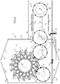
- the installation 1 comprises, firstly, a unit 4 for forming the containers 2 (by blow molding or stretch blow molding) from the blanks 3.
- This forming unit 4 comprises a main conveyor 5 which defines a forming path T1 .
- the main conveyor 5 is a rotating carousel, which comprises a wheel mounted to rotate around a main axis X1 .
- the forming path T1 is circular.
- the forming unit 4 comprises a plurality of forming stations 6 carried by the main conveyor 5 and each including a mold 7 in the cavity of a container 3.
- each mold 7 comprises two half-molds articulated around a common hinge so as to be either separated from each other (in the open position of the mold 7), or joined together (in the closed position of the mold 7).
- Each mold 7 is equipped with an opening and closing mechanism (eg connecting rods and cam).
- Each forming station 6 further comprises a device for injecting, into each blank 3 housed in the mold 7, a fluid under pressure (for example air) to deform the blank 3 until it gives it the imprint of the container model when the material is pressed internally against the mold 7.
- a fluid under pressure for example air
- the forming unit 4 is a stretch-blow molding machine, and each forming station 6 is equipped with a stretching rod mounted in translation relative to the mold 7 to stretch the blank 3 at the same time that it is blown by fluid injection.
- the forming unit 4 comprises a main motorization M1 coupled to the main conveyor 5 to move the forming stations 6 along the forming path T1 . More specifically, in the example shown, the forming stations 6 are driven in a cyclic rotary motion.
- the main conveyor 5 (in the form of a carousel) is provided with a main shaft 8 : it is to this main shaft 8 that the main motorization M1 is coupled.
- the main motorization M1 is of the torque motor type, that is to say it is a brushless servomotor with permanent magnets (also called synchronous motor with permanent magnets, or brushless DC motor).
- This motorization M1 thus comprises a central rotor 9 , directly mounted on the main shaft 8 (and integral in rotation with the latter) and a peripheral stator 10 .
- the main motorization M1 comprises one or more coils integral with the stator 10, and a series of permanent magnets integral with the rotor 9.
- the coil When the coil is traversed by an electric current, it induces in the magnets permanent electromotive force which drives the rotor 9 of a rotational movement whose speed is proportional to the intensity of the current.
- the installation 1 comprises, secondly, a control unit 11 (electronic or computer) controlling the main motorization M1 .
- the control unit 11 is programmable; it is connected to the main engine 8 by a connection which can be wired or radio frequency.
- the control unit 11 is presented eg. in the form of an industrial programmable logic controller (PLC), provided with control electronics (e.g. a processor) and a man-machine interface (typically a screen associated with a keyboard, or possibly a touch screen) by which a operator can enter instructions or read information relating to the operation of the installation 1.
- PLC programmable logic controller
- control unit 11 is connected to the stator 10 to control the intensity of the current delivered to the coil.
- the installation 1 comprises, thirdly, a unit 12 for the preliminary treatment of the blanks 3.
- the processing unit 12 is equipped with radiating walls 13 in front of which the blanks 3 are moved to be exposed to radiation.
- the processing unit 12 is a thermal conditioning (that is to say heating) unit for the blanks 3, arranged to bring them to a temperature above the glass transition temperature of the material (which is approximately 80°C for PET).
- the radiating walls 13 are provided with sources of infrared radiation, typically halogen lamps.
- the processing unit 12 is an ultraviolet radiation decontamination unit.
- the radiating walls 13 are provided with sources of ultraviolet radiation, typically discharge and mercury vapor lamps.
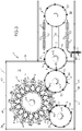
- the processing unit 1 comprises a secondary conveyor 14 which defines a processing path T2 traversed (at least partially) by the blanks 3, as well as a plurality of members 15 for gripping the blanks 3, carried by the secondary conveyor 14 .
- the secondary conveyor 14 comprises eg. a chain
- the grippers 15 can be in the form of devices called spinners, equipped with a mandrel which is fitted into the neck of each blank 3 to, during the course of the treatment path T2 , rotate the blank 3 during its exposure to the radiation from the walls 13.
- the illustrated treatment path T2 comprises two straight portions—each lined with radiating walls 13 facing one another—connected to each other by two curved portions.
- the curved portions of the processing path T2 are defined by wheels provided with grippers for the blanks 3, which does not necessarily correspond to the material reality of the processing unit 12 but has the merit of schematizing rough its architecture.
- the secondary conveyor 14 comprises a drive wheel 16 rotatably mounted on a secondary axis X2 , materialized by a secondary shaft 17 .
- the grippers 15 illustrated here are pliers distributed around the periphery of the drive wheel 16 , each provided with a pair of jaws capable of snapping onto the neck of a blank 3.
- the processing unit 12 comprises a secondary motorization M2 , coupled to the secondary conveyor 14 (here to the wheel secondary).
- This secondary motorization M2 is independent of the main motorization M1 and is controlled by the control unit 11 .
- the control unit 11 is connected to the secondary motorization by a connection which can be wired or radio frequency.
- the secondary motorization M2 is advantageously of the torque-motor type and comprises a rotor 18 secured to the secondary shaft 17 and a stator 19 connected to the control unit 11 which controls the intensity of the supply current.
- the secondary conveyor 14 comprises a follower wheel 20 coupled to the drive wheel 16 , e.g. by means of a belt C.
- the installation 1 comprises a device 21 for supplying the processing unit 12 with blanks 3.
- This supply device 21 comprises eg. an inclined rail from which the blanks 3 are suspended, and along which they slide before entering the processing unit 12 .
- the installation 1 comprises, fourthly, an auxiliary device 22 for upstream transfer of the blanks 3 from the processing unit 12 to the forming unit 4 .
- This upstream transfer auxiliary device 22 comprises an upstream auxiliary conveyor 23 which defines an upstream transfer path T3 .
- the upstream transfer path T3 is tangent to the processing path T2 at a transfer point PT .
- the transfer path T3 is also tangent to the forming path T1 at a loading point PC .
- the upstream auxiliary conveyor 23 is in the form of a wheel, rotatably mounted around an auxiliary axis X3 , materialized by an upstream auxiliary shaft 24 .
- the upstream auxiliary transfer device 22 further comprises a plurality of members 25 for gripping the blanks, carried by the upstream auxiliary conveyor 23 .
- the gripping members 25 are in the form of grippers distributed around the periphery of the wheel, each provided with a pair of jaws capable of being snapped onto the neck of a blank 3.
- the upstream auxiliary transfer device 22 comprises an upstream auxiliary motorization M3 , coupled to the upstream auxiliary conveyor 23 (here at the wheel).
- This M3 engine upstream auxiliary is independent of the main engine M1 and is controlled by the control unit 11 .
- the control unit 11 is connected to the upstream auxiliary motorization M3 by a connection which can be wired or radio frequency.
- the upstream auxiliary motorization M3 is advantageously of the torque-motor type and comprises a rotor 26 integral with the upstream auxiliary shaft 24 , and a stator 27 connected to the control unit 11 which controls the intensity of the supply current.
- the rotational speed of the upstream auxiliary M3 motorization is set to the rotational speed of the main M1 motorization (i.e. the rotational speed of the upstream auxiliary M3 motorization is maintained at a constant fraction of the rotational speed of the main M1 motorization).
- the rotational speed of the secondary M2 motorization it is set to the rotational speed of the upstream auxiliary M3 motorization.
- a fault in the forming unit 4 can be declared, eg. when a mold jams when opening or closing. Such a defect can be detected by means of position or proximity sensors mounted on the molds 7.
- the first phase (A) includes several steps.
- a first step (A.1) consists, for the control unit 11 , (programmed for this purpose), in interrupting the supply of blanks 3 to the processing unit 12 .
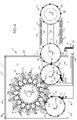
- the installation 1 comprises an actuator 28 movable between a retracted position ( FIG.3 ) in which the actuator 28 is moved away from the path of the blanks 3 to allow their entry into the processing unit 12 , and a deployed position ( FIG.4 ) in which the actuator 28 blocks the blanks 3 to prevent them from being introduced into the processing unit 12 .
- control unit 11 controls the passage of the actuator 28 from its retracted position to its deployed position.
- a second step (A.2) consists for the control unit 11 , (programmed for this purpose), in ordering the desynchronization of the auxiliary motorization M3 upstream of the main motorization M1 .
- the rotation speed of the auxiliary M3 motorization (and therefore the speed of movement of the upstream auxiliary conveyor 23 ) is therefore no longer dependent on the speed of rotation of the main motorization M1 .
- control unit 11 This allows the control unit 11 to control the movement of the upstream auxiliary conveyor 23 without interfering with the movement of the main conveyor 5 .
- a third step (A.3) consists, for the control unit 11 (programmed for this purpose), in controlling the stopping of the main motorization M1 .
- the stoppage of the main engine M1 is not immediate, because the main conveyor 5 is affected by a high inertia due to its mass.
- the stop command for the main M1 motorisation can be carried out either by a gradual reduction in the rotational speed of the main M1 motorisation, or by freewheeling the main M1 motorisation, accompanied by braking. of the secondary shaft 17 (braking controlled by the control unit 11 ). This braking can be controlled via a hydraulic circuit.
- the blanks 3 should be ejected before they reach the loading point PC .
- an ejection point PE located upstream of the loading point PC (in the direction of ordinary movement of the blanks 3 along the transfer path T3 in normal operation of the installation 1).
- upstream is exclusive, that is to say that the ejection point PE cannot be confused with the loading point PC .
- the installation 1 is equipped with an ejector 29 positioned in line with the ejection point PE , movable between an inactive position in which the ejector 29 is moved away from the path of the preforms 3 , and an active position (shown on the FIG.4 ) in which the ejector 29 is interposed on the path of the preforms 3, at the ejection point PE , to deviate them from their trajectory and thus prevent them from being loaded onto the forming unit 4 .
- a fourth step (A.4) of the first phase (A) consists, for the control unit 11 (programmed for this purpose) and as long as the upstream auxiliary motorization M3 is not detected when stopped, to control the ejection of the blanks 3 reaching the ejection point PE .
- control unit 11 controls the passage of the ejector 29 from its inactive position to its active position.
- the second phase (B) consists, for the processing unit 11 , in ordering the maintenance of the synchronization of the secondary motorization M2 on the upstream auxiliary motorization M3 , and in maintaining the ejector 29 in the deployed position.
- the processing unit 12 is emptied of its blanks 3, since they are ejected at the ejection point PE , even though the power supply to the processing unit 12 is stopped.
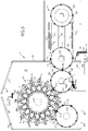
- a first step (C.1) consists, for the control unit 11 (programmed for this purpose), as soon as the processing unit 12 is detected empty of blanks 3, in ordering the desynchronization of the secondary motorization M2 of the auxiliary M3 engine ( FIG.5 ).
- a second step (C.2) consists, for the control unit 11 (programmed for this purpose), as soon as the upstream transfer auxiliary device 22 is detected empty of blanks 3, in controlling the stopping of the motorization Auxiliary M3 ( FIG.6 ).
- the control unit 11 is programmed to keep the secondary motorization M2 moving in a desynchronized manner from the auxiliary motorization M3 .
- the radiating walls 13 can be maintained under voltage, although it is preferable to reduce the power to minimize energy consumption. Keeping the walls 13 under tension makes it possible to avoid their preheating on restarting.
- the installation 1 comprises an auxiliary device 30 for the downstream transfer of the containers 2 formed from the forming unit 4 to one (or more) other machine(s). s), arranged to perform additional operations on the containers 2 (typically filling, capping, labeling).
- This downstream transfer auxiliary device 30 comprises a downstream auxiliary conveyor 31 which defines a downstream transfer path T4 .
- the downstream transfer path T4 is tangent to the forming path T1 at an unloading point PD .
- the downstream auxiliary transfer device 30 is in the form of a wheel, rotatably mounted around a downstream auxiliary axis X4 , materialized by a downstream auxiliary shaft 32 .
- the auxiliary downstream transfer device 30 further comprises a plurality of members 33 for gripping the containers 2, carried by the downstream auxiliary conveyor 31 .
- the gripping members 33 are in the form of pliers distributed around the periphery of the wheel, each provided with a pair of jaws capable of being snapped onto the neck of a container 2.
- the downstream auxiliary transfer device 30 comprises a downstream auxiliary motorization M4 , coupled to the downstream auxiliary conveyor 31 (here to the wheel).
- This downstream auxiliary motorization M4 is independent of the main motorization M1 and is controlled by the control unit 11 .
- the control unit 11 is connected to the downstream auxiliary motorization M4 by a connection which can be wired or radio frequency.
- the downstream auxiliary motorization M4 is advantageously of the torque motor type and comprises a rotor 34 integral with the downstream auxiliary shaft 32 , and a stator 35 connected to the control unit 11 which controls the intensity of the supply current.
- downstream auxiliary conveyor 31 In normal operation of the installation 1, that is to say as long as no fault is detected in the installation 1, the downstream auxiliary conveyor 31 is moved by its downstream auxiliary motorization M4 , which is synchronized on the main engine M1 to allow, at the unloading point PD , the removal by the downstream auxiliary conveyor 31 , in each open mold 7 , of the containers 2 formed in the forming unit 4 .
- the rotational speed of the downstream auxiliary M4 motorization is set to the rotational speed of the main M1 motorization (i.e. the rotational speed of the downstream auxiliary M4 motorization is maintained at a constant fraction of the rotational speed of the main M1 motorization).
- the control unit 11 maintains in all circumstances this synchronization of the downstream auxiliary motorization M4 with the main motorization M1 .
- the emergency stop of the forming unit 4 is intended to allow a maintenance operation to be carried out thereon. Access to the area in which this operation is to be carried out must be authorized for this purpose.
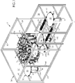
- the installation 1 comprises a cowling 36 defining a main enclosure 37 in which is housed the forming unit 4 (and, possibly, the transfer device(s) 22, 30 ).
- the cowling 36 also defines a secondary enclosure 38 , separated from the main enclosure 37 , and in which the processing unit 12 is at least partially housed.
- cowling 36 defines two separate enclosures 37, 38 which allow separate access, on the one hand, to the forming unit 4 and, on the other hand, to the processing unit 12 , it is not necessary that the processing unit 12 is stopped to allow access to the enclosure 37 main.
- control unit 11 can be programmed to, as soon as the main motorization M1 is detected when stopped, command the unlocking of the main opening 41 , as illustrated on the FIG.5 , where we see that the main opening 41 is open, even though the processing unit 12 continues to rotate.
- control unit 11 can, in addition, be programmed to, when the upstream auxiliary motorization M3 is detected when stopped, command unlocking the sash 44 secondary, as shown in the FIG.7 , where we see that the main opening 41 (or several main openings 41 ) is (are) open.
- the installation comprises an ejector 46 positioned on the downstream transfer path T4 , so as to minimize the risk that containers 2 continue their journey in the installation 1.
- the ejector 46 is connected to the control unit 11 , which controls its operation.
- a step (A.5) is provided which consists, for the control unit 11 , in ordering the movement of the ejector 46 towards a deployed position (illustrated on the FIG.4 ) in which it obstructs the passage of the containers 2 on the downstream transfer path T4 , so as to deflect them therefrom.
- the motorizations M1, M2, M3 cannot be synchronized immediately: they should be put into rotation gradually, then to converge (on command from the control unit 11 ) each speed towards the nominal speed corresponding to operation at full speed.
Landscapes
- Engineering & Computer Science (AREA)
- Manufacturing & Machinery (AREA)
- Mechanical Engineering (AREA)
- Physics & Mathematics (AREA)
- Thermal Sciences (AREA)
- Blow-Moulding Or Thermoforming Of Plastics Or The Like (AREA)
- Control Of Conveyors (AREA)
Claims (12)
- Anlage (1) zur Herstellung von Behältern (2) aus Kunststoffrohlingen (3), umfassend:- eine Einheit (4) zum Formen der Behälter (2) aus den Rohlingen (3), umfassend:• einen Hauptförderer (5), der eine Formgebungsbahn (T1) definiert;• mehrere Formgebungsstationen (6), die vom Hauptförderer (5) getragen werden und jeweils eine Form (7) mit dem Abdruck eines Behälters (2) beinhalten;• einen mit dem Hauptförderer (5) gekoppelten Hauptantrieb (M1) zum Bewegen der Formgebungsstationen (6) entlang der Formgebungsbahn (T1);- eine Einheit (12) zur vorherigen Aufbereitung der Rohlinge (3), umfassend:• einen Nebenförderer (14), der eine Aufbereitungsbahn (T2) definiert;• mehrere Organe (15) zum Greifen der Rohlinge (3), die durch den Nebenförderer (14) getragen werden;- eine Hilfsvorrichtung (22) für den Transfer der Rohlinge (3) von der Aufbereitungseinheit (12) zur Formgebungseinheit (4), umfassend:• einen Hilfsförderer (23), der eine Transferbahn (T3) definiert, die die Aufbereitungsbahn (T2) an einem Transferpunkt (PT) und die Formgebungsbahn an einem Ladepunkt (PC) tangiert;• mehrere Organe (25) zum Greifen der Rohlinge (3), die durch den Hilfsförderer (23) getragen werden;- eine Steuereinheit (11), die den Hauptantrieb (M1) steuert;- wobei die Einheit (12) zur Aufbereitung der Rohlinge einen Nebenantrieb (M2) umfasst, der mit dem Nebenförderer (14) gekoppelt ist, vom Hauptantrieb (M1) unabhängig ist und durch die Steuereinheit (11) gesteuert wird;- wobei die Transferhilfsvorrichtung (22) einen Hilfsantrieb (M3) umfasst, der mit dem Hilfsförderer (23) gekoppelt ist, vom Hauptantrieb (M1) unabhängig ist und durch die Steuereinheit (11) gesteuert wird;- wobei die Steuereinheit (11) dazu programmiert ist: solange zumindest in der Formgebungseinheit (4) kein Fehler erkannt wird, den Hilfsantrieb (M3) mit dem Hauptantrieb (M1) zu synchronisieren und den Nebenantrieb (M2) mit dem Hilfsantrieb (M3) zu synchronisieren;- wobei diese Anlage (1) dadurch gekennzeichnet ist, dass die Steuereinheit (11) ferner dazu programmiert ist: sobald in der Formgebungseinheit (4) ein Fehler erkannt wird:(A.1) die Zufuhr von Rohlingen (3) zur Aufbereitungseinheit (12) zu unterbrechen;(A.2) die Desynchronisierung des Hilfsantriebs (M3) vom Hauptantrieb (M1) zu steuern;(A.3) das Stoppen des Hauptantriebs (M1) zu steuern.
- Anlage (1) nach Anspruch 1, dadurch gekennzeichnet, dass die Steuereinheit (11) ferner dazu programmiert ist, sobald ein Fehler in der Formgebungseinheit (4) detektiert wird:
(A.4) den Auswurf der Rohlinge (3), die an einem stromaufwärts des Ladepunkts (PC) befindlichen Auswurfpunkt (PE) ankommen, zu steuern. - Anlage (1) nach Anspruch 1 oder Anspruch 2, dadurch gekennzeichnet, dass die Steuereinheit (11) dazu programmiert ist, sobald festgestellt wird, dass die Aufbereitungseinheit (12) leer von Rohlingen (3) ist, die Desynchronisierung des Nebenantriebs (M2) vom Hilfsantrieb (M3) zu steuern.
- Anlage (1) nach Anspruch 3, dadurch gekennzeichnet, dass die Aufbereitungseinheit (12) dazu programmiert ist, sobald festgestellt wird, dass die Transferhilfsvorrichtung (22) leer von Rohlingen (3) ist, das Stoppen des Hilfsantriebs (M3) zu steuern.
- Anlage (1) nach Anspruch 3 oder Anspruch 4, dadurch gekennzeichnet, dass die Aufbereitungseinheit (12) dazu programmiert ist, den Nebenantrieb (M2) desynchronisiert zum Hilfsantrieb (M3) in Bewegung zu halten.
- Anlage (1) nach einem der vorangehenden Ansprüche, dadurch gekennzeichnet, dass jeder Antrieb (M1, M2, M3) ein Drehmomentmotor ist.
- Anlage (1) nach einem der vorangehenden Ansprüche, dadurch gekennzeichnet, dass sie eine Verkleidung (36) umfasst, die eine Hauptkammer (37), in der die Formgebungseinheit (4) angeordnet ist, und eine von der Hauptkammer (37) getrennte Nebenkammer (38), in der zumindest teilweise die Aufbereitungseinheit (12) angeordnet ist, definiert, wobei die Verkleidung (36) Folgendes umfasst:- einen Rahmen (39), der zumindest eine Hauptzarge (40) definiert, die die Hauptkammer (37) einfasst;- zumindest einen Hauptflügel (41), der an der Hauptzarge (40) zwischen einer offenen Position, in der der Hauptflügel (41) von der Hauptzarge (40) beabstandet ist, um den Zugang zur Hauptkammer (37) von außen zu gewähren, und einer geschlossenen Position, in der der Hauptflügel (41) in der Hauptzarge (40) angeordnet ist, um den Zugang zur Hauptkammer (37) von außen zu verhindern, montiert ist;- ein System (42) zum Verriegeln und Entriegeln des Hauptflügels (41) in der geschlossenen Position, das mit der Steuereinheit (11) verbunden ist.
- Anlage (1) nach Anspruch 7, dadurch gekennzeichnet, dass die Steuereinheit (11) dazu programmiert ist, sobald festgestellt wird, dass der Hauptantrieb (M1) gestoppt ist, die Entriegelung des Hauptflügels (41) zu steuern.
- Anlage (1) nach einem der vorangehenden Ansprüche, dadurch gekennzeichnet, dass die Steuereinheit (11) dazu programmiert ist, sobald festgestellt wird, dass die Formgebungseinheit (4) betriebsbereit ist,∘ den Hauptantrieb (M1) neu zu starten;∘ den Hilfsantrieb (M3) neu zu starten, wenn festgestellt wird, dass er gestoppt ist;∘ den Hilfsantrieb (M3) wieder mit dem Hauptantrieb (M1) zu synchronisieren;∘ die Versorgung der Aufbereitungseinheit (12) mit Rohlingen (3) zu entsperren.
- Verfahren zum Steuern einer Anlage (1) zur Herstellung von Behältern nach einem der vorangehenden Ansprüche, umfassend die folgenden, durch die Steuereinheit (11) gesteuerten Vorgänge:o solange zumindest in der Formgebungseinheit (4) kein Fehler erkannt wird, den Hilfsantrieb (M3) mit dem Hauptantrieb (M1) zu synchronisieren und den Nebenantrieb (M2) mit dem Hilfsantrieb (M3) zu synchronisieren;o sobald in der Formgebungseinheit (4) ein Fehler erkannt wird:(A.1) die Zufuhr von Rohlingen (3) zur Aufbereitungseinheit (12) zu unterbrechen;(A.2) die Desynchronisierung des Hilfsantriebs (M3) vom Hauptantrieb (M1) zu steuern;(A.3) das Stoppen des Hauptantriebs (M1) zu steuern.
- Verfahren nach Anspruch 10, umfassend, sobald in der Formgebungseinheit (4) ein Fehler detektiert wird, den Vorgang, der darin besteht:
(A.4) den Auswurf der Rohlinge (3), die an einem stromaufwärts des Ladepunkts (PC) befindlichen Auswurfpunkt (PE) ankommen, zu steuern. - Verfahren nach Anspruch 10 oder Anspruch 11, umfassend die durch die Steuereinheit (11) gesteuerten Vorgänge, die darin bestehen, sobald festgestellt wurde, dass die Formgebungseinheit (4) betriebsbereit ist:o den Hauptantrieb (M1) neu zu starten;o den Hilfsantrieb (M3) neu zu starten, wenn festgestellt wird, dass er gestoppt ist;o den Hilfsantrieb (M3) wieder mit dem Hauptantrieb (M1) zu synchronisieren;o die Versorgung der Aufbereitungseinheit (12) Rohlingen (3) zu entsperren.
Applications Claiming Priority (2)
| Application Number | Priority Date | Filing Date | Title |
|---|---|---|---|
| FR1854934A FR3082139B1 (fr) | 2018-06-07 | 2018-06-07 | Installation de production de recipients a arret d'urgence selectif |
| PCT/FR2019/051366 WO2019234364A1 (fr) | 2018-06-07 | 2019-06-06 | Installation de production de recipients a arret d'urgence selectif |
Publications (2)
| Publication Number | Publication Date |
|---|---|
| EP3802056A1 EP3802056A1 (de) | 2021-04-14 |
| EP3802056B1 true EP3802056B1 (de) | 2022-03-30 |
Family
ID=63722515
Family Applications (1)
| Application Number | Title | Priority Date | Filing Date |
|---|---|---|---|
| EP19737853.2A Active EP3802056B1 (de) | 2018-06-07 | 2019-06-06 | Anlage zur herstellung von behältern mit wählbarem notstop |
Country Status (3)
| Country | Link |
|---|---|
| EP (1) | EP3802056B1 (de) |
| FR (1) | FR3082139B1 (de) |
| WO (1) | WO2019234364A1 (de) |
Cited By (1)
| Publication number | Priority date | Publication date | Assignee | Title |
|---|---|---|---|---|
| WO2025040274A1 (de) * | 2023-08-23 | 2025-02-27 | Khs Gmbh | Behältertransportvorrichtung zum transport von behältern |
Families Citing this family (1)
| Publication number | Priority date | Publication date | Assignee | Title |
|---|---|---|---|---|
| EP4613677A1 (de) * | 2024-03-06 | 2025-09-10 | Syntegon Technology A/S | Vorrichtung, system und verfahren zum kontinuierlichen zuführen von behältern |
Family Cites Families (5)
| Publication number | Priority date | Publication date | Assignee | Title |
|---|---|---|---|---|
| FR2881979B1 (fr) | 2005-02-17 | 2007-04-27 | Sidel Sas | Procede de commande d'une machine de soufflage de recipients visant a corriger des anomalies dans la repartition de matiere |
| DE102012102358A1 (de) * | 2012-03-20 | 2013-09-26 | Krones Ag | Verfahren zum Behandeln von Kunststoffbehältnissen mit Zeitreduzierung beim Synchronisieren von Anlagenteilen |
| DE102013014618B4 (de) * | 2013-09-04 | 2015-06-11 | Khs Corpoplast Gmbh | Synchronlaufsicherung für Übergabestationen für Vorrichtungen zum Handhaben von Behältern |
| DE102014005321A1 (de) * | 2014-04-10 | 2015-10-15 | Khs Corpoplast Gmbh | Vorrichtung und Verfahren zum Transportieren und Handhaben von Behältern |
| FR3050446B1 (fr) * | 2016-04-25 | 2019-06-28 | Sidel Participations | Installation de manutention de corps creux, comprenant un convoyeur de distribution et des unites de traitement satellites |
-
2018
- 2018-06-07 FR FR1854934A patent/FR3082139B1/fr active Active
-
2019
- 2019-06-06 EP EP19737853.2A patent/EP3802056B1/de active Active
- 2019-06-06 WO PCT/FR2019/051366 patent/WO2019234364A1/fr not_active Ceased
Cited By (1)
| Publication number | Priority date | Publication date | Assignee | Title |
|---|---|---|---|---|
| WO2025040274A1 (de) * | 2023-08-23 | 2025-02-27 | Khs Gmbh | Behältertransportvorrichtung zum transport von behältern |
Also Published As
| Publication number | Publication date |
|---|---|
| FR3082139B1 (fr) | 2020-07-17 |
| FR3082139A1 (fr) | 2019-12-13 |
| EP3802056A1 (de) | 2021-04-14 |
| WO2019234364A1 (fr) | 2019-12-12 |
Similar Documents
| Publication | Publication Date | Title |
|---|---|---|
| EP3288742B2 (de) | Verfahren zur steuerung eines förderers für hohlkörper durch eine aufheizstation | |
| EP3239079B1 (de) | Förderanlage für hohlkörper, die ein förderband zur verteilung und satelliteneinheiten zur bearbeitung umfasst | |
| EP3431254B1 (de) | Wartungsverfahren einer formanlage von behältern, einschliesslich resynchronisierungsverfahren | |
| EP2382144B1 (de) | Anlage zur herstellung von gefässen mit einem übertragungsrad mit verstellbarem schritt | |
| EP3446851B1 (de) | Regulierungsverfahren einer anlage zur bearbeitung einer folge von behältern, und entsprechende anlage | |
| EP2292406B1 (de) | Maschine zur Herstellung von Behältern, die ein Steuermodul der Vorrichtungen einer Formgusseinheit im Hinblick auf einen Wechsel der Gussform umfasst | |
| EP3802056B1 (de) | Anlage zur herstellung von behältern mit wählbarem notstop | |
| EP2170580A1 (de) | Anlage zur herstellung von behältern aus einem vorformling und verfahren zur steuerung des blasformmittels solch einer anlage | |
| FR2990639A1 (fr) | "installation pour la fabrication de recipients comportant un robot agence pour intervenir sur au moins deux unites" | |
| EP3873717B1 (de) | Verfahren und vorrichtung für die verwaltung von in einer heizvorrichtung immobilisierten vorformlingen | |
| EP3427917B1 (de) | Spannfuttervorrichtung zum fördern von hohlkörpern, und anlage zur herstellung von behältern | |
| EP3538459B1 (de) | System zum befördern von gegenständen aus einem thermoplastischen material mit einem hohlkörper mit einem hals | |
| WO2019234363A1 (fr) | Installation de production de recipients a arret d'urgence progressif | |
| EP0998382B1 (de) | Verfahren und installation zum herstellen von behältern durch blasformen von vorformlingen aus kunststoff | |
| WO1997005999A1 (fr) | Dispositif de moulage de recipients en materiau thermoplastique et installation de fabrication de recipients en faisant application | |
| EP3272491B1 (de) | Steuerungsververfahren von herstellungsvorrichtung mittels sicherung des zugangs für wartung | |
| FR3032698A1 (fr) | "dispositif de convoyage de recipients comportant un organe de prehension mobile transversalement a la direction de deplacement" | |
| EP3774278B2 (de) | Verfahren und vorrichtung zur verwaltung einer rotierenden verarbeitungseinheit | |
| EP4286137B1 (de) | Verfahren zur thermischen konditionierung von vorformlingen | |
| EP3655692B1 (de) | Anlage zur handhabung von gegenständen mit sicherer wartung | |
| WO2020070416A1 (fr) | Procédé et dispositif de gestion de module d'une ligne de production de récipients | |
| FR3053621A1 (fr) | Procede de fabrication de recipients en plastique par soufflage | |
| FR3090604A1 (fr) | « Dispositif de convoyage de préformes pour un four et procédé de commande d’un tel dispositif » | |
| FR3086574A1 (fr) | Installation de fabrication de corps creux comportant un organe de regulation de la circulation des corps creux mu par un moteur electrique lineaire |
Legal Events
| Date | Code | Title | Description |
|---|---|---|---|
| STAA | Information on the status of an ep patent application or granted ep patent |
Free format text: STATUS: UNKNOWN |
|
| STAA | Information on the status of an ep patent application or granted ep patent |
Free format text: STATUS: THE INTERNATIONAL PUBLICATION HAS BEEN MADE |
|
| PUAI | Public reference made under article 153(3) epc to a published international application that has entered the european phase |
Free format text: ORIGINAL CODE: 0009012 |
|
| STAA | Information on the status of an ep patent application or granted ep patent |
Free format text: STATUS: REQUEST FOR EXAMINATION WAS MADE |
|
| 17P | Request for examination filed |
Effective date: 20210106 |
|
| AK | Designated contracting states |
Kind code of ref document: A1 Designated state(s): AL AT BE BG CH CY CZ DE DK EE ES FI FR GB GR HR HU IE IS IT LI LT LU LV MC MK MT NL NO PL PT RO RS SE SI SK SM TR |
|
| AX | Request for extension of the european patent |
Extension state: BA ME |
|
| DAV | Request for validation of the european patent (deleted) | ||
| DAX | Request for extension of the european patent (deleted) | ||
| GRAP | Despatch of communication of intention to grant a patent |
Free format text: ORIGINAL CODE: EPIDOSNIGR1 |
|
| STAA | Information on the status of an ep patent application or granted ep patent |
Free format text: STATUS: GRANT OF PATENT IS INTENDED |
|
| INTG | Intention to grant announced |
Effective date: 20211213 |
|
| GRAJ | Information related to disapproval of communication of intention to grant by the applicant or resumption of examination proceedings by the epo deleted |
Free format text: ORIGINAL CODE: EPIDOSDIGR1 |
|
| STAA | Information on the status of an ep patent application or granted ep patent |
Free format text: STATUS: REQUEST FOR EXAMINATION WAS MADE |
|
| GRAP | Despatch of communication of intention to grant a patent |
Free format text: ORIGINAL CODE: EPIDOSNIGR1 |
|
| STAA | Information on the status of an ep patent application or granted ep patent |
Free format text: STATUS: GRANT OF PATENT IS INTENDED |
|
| GRAS | Grant fee paid |
Free format text: ORIGINAL CODE: EPIDOSNIGR3 |
|
| GRAA | (expected) grant |
Free format text: ORIGINAL CODE: 0009210 |
|
| STAA | Information on the status of an ep patent application or granted ep patent |
Free format text: STATUS: THE PATENT HAS BEEN GRANTED |
|
| INTC | Intention to grant announced (deleted) | ||
| INTG | Intention to grant announced |
Effective date: 20220214 |
|
| AK | Designated contracting states |
Kind code of ref document: B1 Designated state(s): AL AT BE BG CH CY CZ DE DK EE ES FI FR GB GR HR HU IE IS IT LI LT LU LV MC MK MT NL NO PL PT RO RS SE SI SK SM TR |
|
| REG | Reference to a national code |
Ref country code: GB Ref legal event code: FG4D Free format text: NOT ENGLISH |
|
| REG | Reference to a national code |
Ref country code: CH Ref legal event code: EP |
|
| REG | Reference to a national code |
Ref country code: AT Ref legal event code: REF Ref document number: 1478777 Country of ref document: AT Kind code of ref document: T Effective date: 20220415 |
|
| REG | Reference to a national code |
Ref country code: DE Ref legal event code: R096 Ref document number: 602019013157 Country of ref document: DE |
|
| REG | Reference to a national code |
Ref country code: IE Ref legal event code: FG4D Free format text: LANGUAGE OF EP DOCUMENT: FRENCH |
|
| REG | Reference to a national code |
Ref country code: LT Ref legal event code: MG9D |
|
| PG25 | Lapsed in a contracting state [announced via postgrant information from national office to epo] |
Ref country code: SE Free format text: LAPSE BECAUSE OF FAILURE TO SUBMIT A TRANSLATION OF THE DESCRIPTION OR TO PAY THE FEE WITHIN THE PRESCRIBED TIME-LIMIT Effective date: 20220330 Ref country code: RS Free format text: LAPSE BECAUSE OF FAILURE TO SUBMIT A TRANSLATION OF THE DESCRIPTION OR TO PAY THE FEE WITHIN THE PRESCRIBED TIME-LIMIT Effective date: 20220330 Ref country code: NO Free format text: LAPSE BECAUSE OF FAILURE TO SUBMIT A TRANSLATION OF THE DESCRIPTION OR TO PAY THE FEE WITHIN THE PRESCRIBED TIME-LIMIT Effective date: 20220630 Ref country code: LT Free format text: LAPSE BECAUSE OF FAILURE TO SUBMIT A TRANSLATION OF THE DESCRIPTION OR TO PAY THE FEE WITHIN THE PRESCRIBED TIME-LIMIT Effective date: 20220330 Ref country code: HR Free format text: LAPSE BECAUSE OF FAILURE TO SUBMIT A TRANSLATION OF THE DESCRIPTION OR TO PAY THE FEE WITHIN THE PRESCRIBED TIME-LIMIT Effective date: 20220330 Ref country code: BG Free format text: LAPSE BECAUSE OF FAILURE TO SUBMIT A TRANSLATION OF THE DESCRIPTION OR TO PAY THE FEE WITHIN THE PRESCRIBED TIME-LIMIT Effective date: 20220630 |
|
| REG | Reference to a national code |
Ref country code: NL Ref legal event code: MP Effective date: 20220330 |
|
| REG | Reference to a national code |
Ref country code: AT Ref legal event code: MK05 Ref document number: 1478777 Country of ref document: AT Kind code of ref document: T Effective date: 20220330 |
|
| PG25 | Lapsed in a contracting state [announced via postgrant information from national office to epo] |
Ref country code: LV Free format text: LAPSE BECAUSE OF FAILURE TO SUBMIT A TRANSLATION OF THE DESCRIPTION OR TO PAY THE FEE WITHIN THE PRESCRIBED TIME-LIMIT Effective date: 20220330 Ref country code: GR Free format text: LAPSE BECAUSE OF FAILURE TO SUBMIT A TRANSLATION OF THE DESCRIPTION OR TO PAY THE FEE WITHIN THE PRESCRIBED TIME-LIMIT Effective date: 20220701 Ref country code: FI Free format text: LAPSE BECAUSE OF FAILURE TO SUBMIT A TRANSLATION OF THE DESCRIPTION OR TO PAY THE FEE WITHIN THE PRESCRIBED TIME-LIMIT Effective date: 20220330 |
|
| PG25 | Lapsed in a contracting state [announced via postgrant information from national office to epo] |
Ref country code: NL Free format text: LAPSE BECAUSE OF FAILURE TO SUBMIT A TRANSLATION OF THE DESCRIPTION OR TO PAY THE FEE WITHIN THE PRESCRIBED TIME-LIMIT Effective date: 20220330 |
|
| PG25 | Lapsed in a contracting state [announced via postgrant information from national office to epo] |
Ref country code: SM Free format text: LAPSE BECAUSE OF FAILURE TO SUBMIT A TRANSLATION OF THE DESCRIPTION OR TO PAY THE FEE WITHIN THE PRESCRIBED TIME-LIMIT Effective date: 20220330 Ref country code: SK Free format text: LAPSE BECAUSE OF FAILURE TO SUBMIT A TRANSLATION OF THE DESCRIPTION OR TO PAY THE FEE WITHIN THE PRESCRIBED TIME-LIMIT Effective date: 20220330 Ref country code: RO Free format text: LAPSE BECAUSE OF FAILURE TO SUBMIT A TRANSLATION OF THE DESCRIPTION OR TO PAY THE FEE WITHIN THE PRESCRIBED TIME-LIMIT Effective date: 20220330 Ref country code: PT Free format text: LAPSE BECAUSE OF FAILURE TO SUBMIT A TRANSLATION OF THE DESCRIPTION OR TO PAY THE FEE WITHIN THE PRESCRIBED TIME-LIMIT Effective date: 20220801 Ref country code: ES Free format text: LAPSE BECAUSE OF FAILURE TO SUBMIT A TRANSLATION OF THE DESCRIPTION OR TO PAY THE FEE WITHIN THE PRESCRIBED TIME-LIMIT Effective date: 20220330 Ref country code: EE Free format text: LAPSE BECAUSE OF FAILURE TO SUBMIT A TRANSLATION OF THE DESCRIPTION OR TO PAY THE FEE WITHIN THE PRESCRIBED TIME-LIMIT Effective date: 20220330 Ref country code: CZ Free format text: LAPSE BECAUSE OF FAILURE TO SUBMIT A TRANSLATION OF THE DESCRIPTION OR TO PAY THE FEE WITHIN THE PRESCRIBED TIME-LIMIT Effective date: 20220330 Ref country code: AT Free format text: LAPSE BECAUSE OF FAILURE TO SUBMIT A TRANSLATION OF THE DESCRIPTION OR TO PAY THE FEE WITHIN THE PRESCRIBED TIME-LIMIT Effective date: 20220330 |
|
| PG25 | Lapsed in a contracting state [announced via postgrant information from national office to epo] |
Ref country code: PL Free format text: LAPSE BECAUSE OF FAILURE TO SUBMIT A TRANSLATION OF THE DESCRIPTION OR TO PAY THE FEE WITHIN THE PRESCRIBED TIME-LIMIT Effective date: 20220330 Ref country code: IS Free format text: LAPSE BECAUSE OF FAILURE TO SUBMIT A TRANSLATION OF THE DESCRIPTION OR TO PAY THE FEE WITHIN THE PRESCRIBED TIME-LIMIT Effective date: 20220730 Ref country code: AL Free format text: LAPSE BECAUSE OF FAILURE TO SUBMIT A TRANSLATION OF THE DESCRIPTION OR TO PAY THE FEE WITHIN THE PRESCRIBED TIME-LIMIT Effective date: 20220330 |
|
| REG | Reference to a national code |
Ref country code: DE Ref legal event code: R097 Ref document number: 602019013157 Country of ref document: DE |
|
| PG25 | Lapsed in a contracting state [announced via postgrant information from national office to epo] |
Ref country code: MC Free format text: LAPSE BECAUSE OF FAILURE TO SUBMIT A TRANSLATION OF THE DESCRIPTION OR TO PAY THE FEE WITHIN THE PRESCRIBED TIME-LIMIT Effective date: 20220330 Ref country code: DK Free format text: LAPSE BECAUSE OF FAILURE TO SUBMIT A TRANSLATION OF THE DESCRIPTION OR TO PAY THE FEE WITHIN THE PRESCRIBED TIME-LIMIT Effective date: 20220330 |
|
| REG | Reference to a national code |
Ref country code: CH Ref legal event code: PL |
|
| PLBE | No opposition filed within time limit |
Free format text: ORIGINAL CODE: 0009261 |
|
| STAA | Information on the status of an ep patent application or granted ep patent |
Free format text: STATUS: NO OPPOSITION FILED WITHIN TIME LIMIT |
|
| REG | Reference to a national code |
Ref country code: BE Ref legal event code: MM Effective date: 20220630 |
|
| 26N | No opposition filed |
Effective date: 20230103 |
|
| PG25 | Lapsed in a contracting state [announced via postgrant information from national office to epo] |
Ref country code: LU Free format text: LAPSE BECAUSE OF NON-PAYMENT OF DUE FEES Effective date: 20220606 Ref country code: LI Free format text: LAPSE BECAUSE OF NON-PAYMENT OF DUE FEES Effective date: 20220630 Ref country code: IE Free format text: LAPSE BECAUSE OF NON-PAYMENT OF DUE FEES Effective date: 20220606 Ref country code: CH Free format text: LAPSE BECAUSE OF NON-PAYMENT OF DUE FEES Effective date: 20220630 |
|
| PG25 | Lapsed in a contracting state [announced via postgrant information from national office to epo] |
Ref country code: SI Free format text: LAPSE BECAUSE OF FAILURE TO SUBMIT A TRANSLATION OF THE DESCRIPTION OR TO PAY THE FEE WITHIN THE PRESCRIBED TIME-LIMIT Effective date: 20220330 Ref country code: BE Free format text: LAPSE BECAUSE OF NON-PAYMENT OF DUE FEES Effective date: 20220630 |
|
| P01 | Opt-out of the competence of the unified patent court (upc) registered |
Effective date: 20230403 |
|
| GBPC | Gb: european patent ceased through non-payment of renewal fee |
Effective date: 20230606 |
|
| PG25 | Lapsed in a contracting state [announced via postgrant information from national office to epo] |
Ref country code: MK Free format text: LAPSE BECAUSE OF FAILURE TO SUBMIT A TRANSLATION OF THE DESCRIPTION OR TO PAY THE FEE WITHIN THE PRESCRIBED TIME-LIMIT Effective date: 20220330 Ref country code: CY Free format text: LAPSE BECAUSE OF FAILURE TO SUBMIT A TRANSLATION OF THE DESCRIPTION OR TO PAY THE FEE WITHIN THE PRESCRIBED TIME-LIMIT Effective date: 20220330 Ref country code: GB Free format text: LAPSE BECAUSE OF NON-PAYMENT OF DUE FEES Effective date: 20230606 |
|
| PG25 | Lapsed in a contracting state [announced via postgrant information from national office to epo] |
Ref country code: HU Free format text: LAPSE BECAUSE OF FAILURE TO SUBMIT A TRANSLATION OF THE DESCRIPTION OR TO PAY THE FEE WITHIN THE PRESCRIBED TIME-LIMIT; INVALID AB INITIO Effective date: 20190606 |
|
| PG25 | Lapsed in a contracting state [announced via postgrant information from national office to epo] |
Ref country code: MT Free format text: LAPSE BECAUSE OF FAILURE TO SUBMIT A TRANSLATION OF THE DESCRIPTION OR TO PAY THE FEE WITHIN THE PRESCRIBED TIME-LIMIT Effective date: 20220330 |
|
| PGFP | Annual fee paid to national office [announced via postgrant information from national office to epo] |
Ref country code: DE Payment date: 20250520 Year of fee payment: 7 |
|
| PGFP | Annual fee paid to national office [announced via postgrant information from national office to epo] |
Ref country code: IT Payment date: 20250520 Year of fee payment: 7 |
|
| PGFP | Annual fee paid to national office [announced via postgrant information from national office to epo] |
Ref country code: FR Payment date: 20250520 Year of fee payment: 7 |
|
| PG25 | Lapsed in a contracting state [announced via postgrant information from national office to epo] |
Ref country code: TR Free format text: LAPSE BECAUSE OF FAILURE TO SUBMIT A TRANSLATION OF THE DESCRIPTION OR TO PAY THE FEE WITHIN THE PRESCRIBED TIME-LIMIT Effective date: 20220330 |