EP4286137B1 - Verfahren zur thermischen konditionierung von vorformlingen - Google Patents
Verfahren zur thermischen konditionierung von vorformlingen Download PDFInfo
- Publication number
- EP4286137B1 EP4286137B1 EP23171079.9A EP23171079A EP4286137B1 EP 4286137 B1 EP4286137 B1 EP 4286137B1 EP 23171079 A EP23171079 A EP 23171079A EP 4286137 B1 EP4286137 B1 EP 4286137B1
- Authority
- EP
- European Patent Office
- Prior art keywords
- preforms
- heating
- diffusion
- duration
- production rate
- Prior art date
- Legal status (The legal status is an assumption and is not a legal conclusion. Google has not performed a legal analysis and makes no representation as to the accuracy of the status listed.)
- Active
Links
Images


Classifications
-
- B—PERFORMING OPERATIONS; TRANSPORTING
- B29—WORKING OF PLASTICS; WORKING OF SUBSTANCES IN A PLASTIC STATE IN GENERAL
- B29C—SHAPING OR JOINING OF PLASTICS; SHAPING OF MATERIAL IN A PLASTIC STATE, NOT OTHERWISE PROVIDED FOR; AFTER-TREATMENT OF THE SHAPED PRODUCTS, e.g. REPAIRING
- B29C49/00—Blow-moulding, i.e. blowing a preform or parison to a desired shape within a mould; Apparatus therefor
- B29C49/42—Component parts, details or accessories; Auxiliary operations
- B29C49/64—Heating or cooling preforms, parisons or blown articles
- B29C49/6409—Thermal conditioning of preforms
- B29C49/6418—Heating of preforms
-
- B—PERFORMING OPERATIONS; TRANSPORTING
- B29—WORKING OF PLASTICS; WORKING OF SUBSTANCES IN A PLASTIC STATE IN GENERAL
- B29C—SHAPING OR JOINING OF PLASTICS; SHAPING OF MATERIAL IN A PLASTIC STATE, NOT OTHERWISE PROVIDED FOR; AFTER-TREATMENT OF THE SHAPED PRODUCTS, e.g. REPAIRING
- B29C49/00—Blow-moulding, i.e. blowing a preform or parison to a desired shape within a mould; Apparatus therefor
- B29C49/42—Component parts, details or accessories; Auxiliary operations
- B29C49/4205—Handling means, e.g. transfer, loading or discharging means
- B29C49/42065—Means specially adapted for transporting preforms
-
- B—PERFORMING OPERATIONS; TRANSPORTING
- B29—WORKING OF PLASTICS; WORKING OF SUBSTANCES IN A PLASTIC STATE IN GENERAL
- B29C—SHAPING OR JOINING OF PLASTICS; SHAPING OF MATERIAL IN A PLASTIC STATE, NOT OTHERWISE PROVIDED FOR; AFTER-TREATMENT OF THE SHAPED PRODUCTS, e.g. REPAIRING
- B29C49/00—Blow-moulding, i.e. blowing a preform or parison to a desired shape within a mould; Apparatus therefor
- B29C49/42—Component parts, details or accessories; Auxiliary operations
- B29C49/4205—Handling means, e.g. transfer, loading or discharging means
- B29C49/42071—Temperature conditioned transport, e.g. insulated or heated transport means
-
- B—PERFORMING OPERATIONS; TRANSPORTING
- B29—WORKING OF PLASTICS; WORKING OF SUBSTANCES IN A PLASTIC STATE IN GENERAL
- B29C—SHAPING OR JOINING OF PLASTICS; SHAPING OF MATERIAL IN A PLASTIC STATE, NOT OTHERWISE PROVIDED FOR; AFTER-TREATMENT OF THE SHAPED PRODUCTS, e.g. REPAIRING
- B29C49/00—Blow-moulding, i.e. blowing a preform or parison to a desired shape within a mould; Apparatus therefor
- B29C49/42—Component parts, details or accessories; Auxiliary operations
- B29C49/64—Heating or cooling preforms, parisons or blown articles
- B29C49/68—Ovens specially adapted for heating preforms or parisons
- B29C49/682—Ovens specially adapted for heating preforms or parisons characterised by the path, e.g. sinusoidal path
-
- B—PERFORMING OPERATIONS; TRANSPORTING
- B29—WORKING OF PLASTICS; WORKING OF SUBSTANCES IN A PLASTIC STATE IN GENERAL
- B29C—SHAPING OR JOINING OF PLASTICS; SHAPING OF MATERIAL IN A PLASTIC STATE, NOT OTHERWISE PROVIDED FOR; AFTER-TREATMENT OF THE SHAPED PRODUCTS, e.g. REPAIRING
- B29C49/00—Blow-moulding, i.e. blowing a preform or parison to a desired shape within a mould; Apparatus therefor
- B29C49/42—Component parts, details or accessories; Auxiliary operations
- B29C49/78—Measuring, controlling or regulating
- B29C2049/7878—Preform or article handling, e.g. flow from station to station
-
- B—PERFORMING OPERATIONS; TRANSPORTING
- B29—WORKING OF PLASTICS; WORKING OF SUBSTANCES IN A PLASTIC STATE IN GENERAL
- B29C—SHAPING OR JOINING OF PLASTICS; SHAPING OF MATERIAL IN A PLASTIC STATE, NOT OTHERWISE PROVIDED FOR; AFTER-TREATMENT OF THE SHAPED PRODUCTS, e.g. REPAIRING
- B29C49/00—Blow-moulding, i.e. blowing a preform or parison to a desired shape within a mould; Apparatus therefor
- B29C49/02—Combined blow-moulding and manufacture of the preform or the parison
- B29C49/06—Injection blow-moulding
-
- B—PERFORMING OPERATIONS; TRANSPORTING
- B29—WORKING OF PLASTICS; WORKING OF SUBSTANCES IN A PLASTIC STATE IN GENERAL
- B29C—SHAPING OR JOINING OF PLASTICS; SHAPING OF MATERIAL IN A PLASTIC STATE, NOT OTHERWISE PROVIDED FOR; AFTER-TREATMENT OF THE SHAPED PRODUCTS, e.g. REPAIRING
- B29C49/00—Blow-moulding, i.e. blowing a preform or parison to a desired shape within a mould; Apparatus therefor
- B29C49/42—Component parts, details or accessories; Auxiliary operations
- B29C49/64—Heating or cooling preforms, parisons or blown articles
- B29C49/68—Ovens specially adapted for heating preforms or parisons
- B29C49/6845—Ovens specially adapted for heating preforms or parisons using ventilation, e.g. a fan
Definitions
- the invention relates to a method for thermally conditioning preforms before their forming, in particular by stretch-blow molding in a container production installation.
- preforms made of thermoplastic material.
- the material forming the preforms is generally in an amorphous state which is not suitable for allowing them to be cold formed. Prior to the forming operation, the preforms are therefore heated to a glass transition temperature which allows them to be shaped into the final container.
- the preforms generally have a substantially cylindrical body of revolution with a thick tubular wall which is closed at one of its axial ends by a thick-walled bottom, and which is extended at its other end by a neck, also tubular.
- the neck is shaped to its final shape and dimensions while the body of the preform is intended to undergo a relatively significant deformation to conform it into a container during a forming step.
- the neck remaining at a temperature below said glass transition temperature to avoid its deformation during the manufacture of the container.
- the body temperature must not exceed a crystallization temperature that is higher than the glass transition temperature. Beyond this crystallization temperature, the thermoplastic material crystallizes and does not no longer has the mechanical properties to achieve the required quality of forming. It is important that the crystallization of the material is induced, in a controlled manner, only during the forming operation so that the polymer chains are oriented in the required directions.
- the production of containers in large series is carried out in a production facility that includes a heating station that allows, during a heating step, to make the body of the preform malleable by heating beyond the glass transition temperature.
- a heating station that allows, during a heating step, to make the body of the preform malleable by heating beyond the glass transition temperature.
- each preform is transported along a heating path exposed to heating radiation.
- the production facility also comprises a forming station which is arranged downstream of the heating station according to the direction of circulation of the preforms in the production facility.
- the hot preform is placed in a forming unit, for example in a mold of the forming station which has a molding imprint conforming to the container to be obtained.
- a pressurized fluid such as air, is then injected into the malleable body of the preform in order to press the wall thereof against the mold imprint.
- the injection of pressurized fluid is preceded and/or accompanied by axial stretching of the preform, in particular by means of a stretching rod inserted into the preform. In a known manner, the body is thus subjected to biaxial stretching.
- each preform is transported along a diffusion path that is not exposed to the heating radiation and that extends from a downstream end of the heating path to the forming station.
- the preforms passively undergo a diffusion step of the heat stored in their wall. This step allows in particular the heat to diffuse into the thickness of the preform wall in order to obtain optimum heat distribution.
- the wall of the preform has an increasing thermal gradient in the direction of its thickness from its external face to its internal face. This gradient is produced by passive diffusion of heat through the wall towards the interior of the preform during the diffusion step.
- each preform is transferred into forming units of the forming station during a transfer step.
- the temperature of the preforms as they move through the production facility is an essential parameter that is important to control in order to obtain a good quality container at the end of the forming stage.
- crystallization of the material may occur before it is formed, causing significant degradation in the quality of the container produced. Such crystallization may occur during heating, or even during transport of the preform from the heating station to the forming station. The latter case may occur when the preform has stored a large amount of heat in its thickness and the diffusion time is too long.
- the body of the preforms is divided into several zones which must be heated to different temperatures in order to control the distribution of the thermoplastic material during the forming operation.
- An area heated to a high temperature will tend to be able to be stretched with less effort than an area heated to a lower temperature.
- the diffusion step must therefore be long enough to obtain an optimum temperature distribution in each area, but short enough so that the thermal boundary between two areas remains sufficiently sharp.
- the diffusion time is dependent on the production rate of the forming station, as explained below.
- the transport of the preforms along the diffusion path is carried out by conveying means comprising individual gripping members for each preform.
- a pitch between two successive preforms is determined as being the distance between these two preforms according to the direction of movement along the diffusion path. At each point on the diffusion path, the pitch between two preforms is fixed independently of the operating rate of the blowing station.
- the pitch is the same at every point along the diffusion path. For other production facilities, it may happen that the pitch is not the same at different locations along the circuit. But even if the pitch changes along the diffusion path, the pitch remains invariant over time at each point along the diffusion path.
- preform speeds are likely to vary proportionally to the production rate, but the step remains independent of the speed at each point of the diffusion path.
- the conveying means of the heating station are often formed by a chain of gripping members articulated to each other, and the conveying means between the heating station and the forming station are formed by at least one wheel comprising at its periphery gripping members fixed or carried by arms.
- the broadcast duration varies proportionally to the production rate. It is therefore known to regulate the production rate so that the broadcast duration remains within a range of values in which the quality of the container obtained is acceptable.
- the production rates at which the production installation is likely to operate are limited to an operating range constrained in particular by the diffusion duration.
- the production rate forms a control setpoint for the production installation, while the diffusion duration only forms a constraint which limits the operating range in which the production rate can vary.
- a setpoint is defined as being a parameter on which an operator can act directly, for example by entering a value in a control panel.
- a constraint is not a parameter on which an operator can act.
- a constraint only limits the values which the operator can assign to a parameter, here the production rate.
- the value range of the diffusion duration is generally fixed by the structural characteristics of the production installation, in particular the length of the diffusion path, which is kept relatively short, in particular for reasons of manufacturing costs of the production installation.
- the diffusion duration could form a control instruction independent of the production rate in order to improve the quality of the container obtained.
- the duration of the diffusion step is controlled independently of the production rate by adaptation of the adjustable duration.
- a broadcast duration setpoint is selected, the adjustable duration being automatically controlled as a function of the production rate to maintain the broadcast duration equal to the setpoint regardless of the production rate.
- the adjustable duration is controlled so that the diffusion duration is identical for each preform.
- the adjustable duration is capable of occupying several values in an interval delimited by a minimum lower limit and by an upper limit for a given production rate.
- the lower bound depends on the length of the final buffer section and the maximum speed likely to be reached by the preform at each point of the final buffer section.
- the upper bound depends on the length of the final buffer section and the production rate.
- the production rate is controllable between a maximum rate and a minimum rate when producing containers, the length of the final buffer section and/or the maximum speed of the preforms on the final buffer section being determined such that the adjustable duration can be controlled so that at least one diffusion duration value can remain constant for any production rate between the maximum rate and the minimum rate.
- the preforms are transported along the final buffer section by shuttles set in motion independently of each other by means of a linear motor or a pneumatic device.
- the preforms move along the final buffer section with an identical speed profile.
- the preforms are transferred successively one by one into the forming station.
- a determined number of several successive preforms form a group, the preforms from the same group being transferred simultaneously to the forming station.
- the successive preforms of the same group move along the final buffer section with different speed profiles so that the diffusion duration is the same for all the preforms of the group.
- the heating step comprises two successive heating sub-steps preceding the diffusion step, the two heating sub-steps being separated by an intermediate step of transporting the preforms in a row, the heating path being divided into an upstream heating section and a downstream heating section connected by a transition path.
- the transition path comprises at least one intermediate buffer section through which the preforms travel in an adjustable duration which is controlled independently of the production rate.
- the preforms 14 move in the production facility 10 along a production route from upstream to downstream.
- the preforms 14 are moved in a row along the production route by conveying means which will be detailed later.
- the containers 12 are here bottles.
- the thermoplastic material is here formed by polyethylene terephthalate, hereinafter referred to by its acronym "PET".
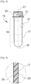
- the preform 14 has a main axis "X1" shown vertically at the figure 3 . It has a cylindrical body 16 with a tubular wall 17 closed at one of its axial ends by a base 18, shown here at the bottom of the figure, and which is opened at its other end by a neck 20, also tubular. At its base, the neck 20 here has a collar 21.
- the wall 17 is delimited by an external face 22 and by an internal face 24.
- the neck 20 generally has its final shape while the body 16 of the preform 14 is intended to undergo a relatively significant deformation to form the final container 12 during a forming step.
- the production installation 10 produced according to the state of the art comprises a station 26 for heating the preforms 14.
- the heating station 26 comprises at least one heating tunnel 27 in which heating emitters 28 emitting heating electromagnetic radiation, for example infrared radiation, are arranged. These heating emitters 28 have the function of heating the body 16 of the preforms 14 above a glass transition temperature to make them sufficiently malleable for forming. The body 16 of the preforms 14 must however remain at a temperature below a crystallization temperature.
- the heating emitters 28 are formed by halogen lamps.
- the heating station 26 generally comprises two heating tunnels 27 so that the preforms 14 can benefit from sufficient exposure time to the heating radiation.
- the heating radiation emitted by such heating emitters 28 is generally absorbed mainly at the external face 22 of the preforms 14.
- the heating tunnels 27 are therefore generally equipped with ventilation means 30 which have the objective of cooling the external face 22 external of the preforms 14 to prevent them from overheating, which could for example lead to their crystallization.
- the heating emitters 28 are arranged on one side of the associated heating tunnel 27 while the ventilation means 30 are arranged on an opposite side of the heating tunnel 27.
- such a production installation 10 made according to the state of the art comprises heating emitters 28 formed by laser emitters.
- the heating radiation emitted by such heating emitters 28 generally penetrates deeper into the thickness of the wall 17.
- the preforms 14 do not need as long an exposure time as with halogen lamps to absorb the amount of heat required for their forming.
- the production installation 10 of the figure 2 therefore comprises a single heating tunnel 27 shorter than the cumulative length of the two heating tunnels 27 of the production installation 10 shown in figure 1 .
- the production facility 10 shown in the figure 2 also does not include ventilation means because the risk of overheating of the preform 14 is low or even zero. It is therefore possible to arrange heating emitters 28 on both sides of the heating tunnel 27.
- the heating station 26 also comprises a device 32 for conveying the preforms 14 over part of their route.
- the conveying device 32 is notably arranged so as to make them scroll along the heating tunnel 27.
- the direction of scrolling of the preforms 14 is indicated by the arrows in the figure 1 .
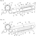
- the conveying device 32 comprises gripping members 33, each of which is capable of individually gripping a preform 14, generally by its neck 20.
- a member 33 gripping is for example formed by a mandrel which is inserted inside the neck 20 of the preform 14 then tightened by radial expansion, as shown in the figure 5 .
- conveying devices 32 There are several types of conveying devices 32.
- the gripping members 33 are for example carried by the links of an endless chain which circulates around two guide wheels, one of which is a drive wheel. In this case, all the gripping members 33 circulate simultaneously at the same speed.
- the conveying device 32 is formed, at least in part, by a linear motor 35.
- FIG. 5 An example of the embodiment of such a linear motor 35 is shown in figure 5 .
- the gripping members 33 are carried by independent shuttles 34.
- the linear motor 35 comprises rails 36 for guiding the shuttles 34, for example by means of rollers 40 carried by the shuttles 34.
- the linear motor 35 also comprises a magnetic track 42 which is arranged along the rails 36.
- the magnetic track 42 forms a stator comprising a series of windings 44 which are distributed along the magnetic track 42.
- Each winding 44 is controlled individually to locally induce a magnetic field independently of the other windings.
- the windings 44 are for example controlled by an electronic control unit (not shown) which is programmed appropriately.
- the gripping members 33 circulate in a row along a closed loop 46.
- the loop here has a straight upstream portion 46A and a straight downstream portion 46C which are parallel.
- the straight portions 46A, 46C are joined by two 180° turn portions 46B, 46D.
- the preforms 14 are conveyed in a row to an entry point 48 of the heating station 26 by a transport wheel 50.
- This is generally a wheel 50 comprising notches 51 on its periphery, called a “notched wheel”, as illustrated schematically in FIG. figure 12 .
- Each notch 51 receives the body 16 of the preform 14 and the weight of the preform 14 being supported by its collar 21.
- the entry point 48 is located on a portion 46D of the bend of the loop 46 of the conveyor device 32.
- the body 16 of the preforms 14 Upon exiting the heating tunnel 27, the body 16 of the preforms 14 is made malleable by heating beyond a glass transition temperature, while the neck 20 is maintained at a temperature low enough to retain its original shape.
- the 10 production facilities of Figures 1 and 2 also comprise a station 52 for forming the preforms 14 thus heated.
- the forming station 52 is arranged downstream of the heating station 26 with reference to the flow of preforms 14 in the production installation 10.
- the forming station 52 here comprises a carousel 54 carrying a plurality of forming units 56.
- the carousel 54 is rotatably mounted about a central axis "X2".
- Each forming unit 56 is thus capable of moving the preforms 14/final containers 12 about the axis "X2" of the carousel 54 between a point 58 for loading the preforms 14 and a point 60 for unloading the final containers 12 to resume a new cycle.
- Each forming unit 56 generally comprises a mold (not shown) in which at least one preform 14 is intended to be received, and forming means (not shown).
- the forming means are generally formed by a nozzle which is capable of injecting a pressurized fluid, in particular air, into the preforms 14 received in the molds.
- the forming means optionally comprise a stretching rod which is intended to be inserted inside the preform 14 to cause it to stretch in an axial direction by contact with the bottom 18.
- the production facility 10 generally comprises means for transporting the hot preforms 14 which move them along a portion of their route from an exit point 62 of the heating station 26 to the loading point 58 in a forming unit 56 of the forming station 52.
- the exit point 62 of the heating station 26 is here located in the same portion 46D of the loop bend as the entry point 48.
- such transport means generally comprise a transfer wheel 64.
- the transfer wheel 64 is provided at its periphery with grippers 65 which are capable of gripping each preform 14 by its neck 20, as illustrated schematically in FIG. figure 12 .
- the neck 20 of the preform 14 is capable of being gripped since the body 16 of the preform 14 has been made malleable by heating.
- the clamps 65 are generally carried by means of arms 67 pivotally mounted on the transfer wheel 64, also illustrated in FIG. figure 12 .
- the grippers 65 may also be mounted sliding along the arms 67.
- the movement of the arms 67 is then controlled by a cam control mechanism so that all the preforms 14 follow the same speed profile during their transfer.
- the grippers 65 grip the preforms at the point 62 output from the forming station 52, thus taking over from the conveying device 32, then they deposit the preforms in the associated forming unit 56 of the forming station 52.
- each preform 14 is heated according to a desired heating profile in the heating station 26.
- the body 16 of each preform 14 is heated in a differentiated manner according to specific zones of the body 16, called "differentiated heating zones".
- differentiated heating zones there is shown in figure 6 a final container 12 obtained by forming the body 16 of the preform 14.
- the body 16 of the final container 12 is here divided into several heating zones differentiated in the axial direction.
- a first zone 16A of the body 16 of the final container 12 located directly under the neck 20 has a conical shape.
- the geometry of this first zone 16A gives it mechanical properties such that it is not necessary for the material thickness of its wall 17 to be very significant.
- this first zone 16A Just below this first zone 16A is a second generally cylindrical zone 16B which generally corresponds to the place where a user will grasp the final container 12. As a result, this second zone 16B must have mechanical resistance properties allowing it to be grasped without crushing the final container 12.
- the wall 17 of this second zone 16B is generally thicker than the first zone 16A. For example, the wall 17 is thicker and/or the wall 17 has grooves to reinforce its resistance to crushing.
- this third zone 16C does not have any particular function. As a result, this third zone 16C generally has a thickness less than that of the second zone 16B.
- this fourth zone 16D corresponds to the zone which supports the weight of the final container 12 and its contents.
- this fourth zone 16D must have mechanical resistance properties making it possible to avoid its crushing under the effect of the weight.
- the wall 17 of this fourth zone 16D generally has a greater thickness than the first and third zones 16A, 16C.
- the wall 17 is thicker and/or the wall 17 has ribs to reinforce its resistance to crushing.
- the final container may also have a non-axisymmetric shape.
- certain zones, this time distributed angularly and not axially, of the body 16 of the preform 14 are intended to be more stretched than others.
- the heating of the preforms 14 according to such a temperature profile is generally known under the term "preferential heating".
- the distribution of the material is not carried out uniformly along the main axis "X1" of the final container 12 during the forming operation.
- the body 16 of the preform 14 is deformed in a differentiated manner according to the zones during the forming operation. As will be explained later, different zones of differentiated heating of the body 16 of the preform 14 may therefore require heating at different temperatures. These zones are shown in figure 4 by broken lines which divide the body 16 into four.
- the body 16 of the preform 14 is heated homogeneously or differentially, it is preferable that, at the time of forming the preforms 14, their wall 17 has, in their thickness, an increasing temperature gradient from its external face 22 to its internal face 24 according to the direction of the thickness.
- a gradient makes it possible to obtain a final container 12 of required quality.
- the forming of the preform 14 requires a lower blowing pressure with such a temperature gradient.
- each preform 14 to a thermal conditioning process which is illustrated in figure 7 .
- the production route is divided into several sections which will subsequently be called journeys.
- the thermal conditioning method conventionally comprises at least a first step "E1" of heating the body 16 of each preform 14 by transport along a heating path 66 exposed to heating radiation.
- the term “heating path 66" refers only to the section of the production route along which the preforms 14 are exposed to the heating radiation emitted by the heating emitters 28.
- the heating path 66 begins as soon as the preforms 14 are exposed to the heating radiation of the heating emitters 28 and it ends as soon as the preforms 14 are substantially no longer exposed to the heating radiation of the heating emitters 28.
- the heating path 66 thus corresponds overall to the section of the production route which passes through the heating tunnel 27.
- the heating path 66 is divided into an upstream heating section 66A and a downstream heating section 66B.
- the heating step "E1" is then divided into two successive heating sub-steps "E1A", "E1B".
- the two heating sub-steps "E1A”, “E1B” are separated by a step “E1int” of intermediate transport of the preforms 14 in a row from a downstream end of the upstream heating section 66A to an upstream end of the downstream heating section 66B along a transition path 68.
- the upstream heating section 66A and the downstream heating section 66B heating are connected by the transition path 68.
- the preforms 14 are not exposed to the heating radiation emitted by the heating emitters 28.
- the conveying device 32 is controlled so that the preforms 14 exit the heating path 66 at a production rate "R" determined, for example by an operator.
- This production rate "R” corresponds to the number of bottles that it is desired to produce per unit of time.
- the first heating step “E1" is immediately followed by a second step “E2" of diffusion of the heat stored in each preform 14 during the first heating step "E1".
- this second diffusion step "E2" the preforms 14 are transported in a row along a diffusion path 70, shown in a frame in the figures, which is not exposed to the heating radiation and which extends from a downstream end of the heating path 66 to the station 52 for forming the preforms 14.
- This diffusion step “E2" must thus last long enough to allow the establishment of this gradient, but it must not be too long so that the boundary between the differentiated heating zones does not become too blurred. It must also not be too long to avoid the appearance of spots that are too hot or too cold in the body 16. It is generally accepted that the duration of this diffusion step “E2", called “diffusion duration "D”, must remain within a range determined according to the preform model 14 to avoid the problems mentioned above while allowing the appearance of the desired temperature gradient.
- the preforms 14 having arrived at the loading point 58, undergo a third step “E3" of transfer into the forming units 56 of the forming station 52 at said determined production rate "R". This means that the preforms 14 come out of the heating station 26 and they enter the forming station 52 at the same production rate "R".
- the preforms 14 are, for example, placed on a forming support, in particular in a mold, of the forming unit 56.
- the diffusion path 70 ends when the preforms 14 have been placed in the forming support, in particular the mold.
- the diffusion duration "D" continued to be considered only as a constraint and not as a control instruction capable of being controlled independently of the production rate "R".
- the invention proposes to obtain final containers 12 of identical quality independently of the production rate "R” by guaranteeing that all the preforms 14 for the production of the same model of final container 12 have an identical diffusion duration "D".
- the invention also makes it possible to extend the operating range over which the production rate "R" can be controlled.
- the invention proposes production installations 100 in which the diffusion path 70 comprises at least one final buffer section 70A that the preforms 14 travel in an adjustable duration "Da".
- the diffusion duration "D” can thus be controlled independently of the production rate "R”.
- the length of the final buffer section 70A must be sufficient to allow the adjustable duration "Da” to be varied over a significantly large interval compared to the broadcast duration "D" as will be explained later.
- dependent duration "Db" of the preforms 14 on certain sections, called dependent sections 70B, of the diffusion path 70 can remain proportional to the production rate "R".
- the final buffer section 70A is here produced by means of a linear motor 35 in which the gripping members 33 of the preforms 14 are loaded onto shuttles 34 which move along a magnetic track 42, in a manner similar to that illustrated in the figure 5 .
- the gripping members 33 may be formed by mandrels, as illustrated in figure 5 , but also by clamps 65 or any other gripping means.
- the preforms 14 are transported along the final buffer section 70A by shuttles 34 set in motion independently of each other by controlling the magnetic track 42.
- Such a transport device makes it possible to vary the speed of the shuttles 34 independently of each other and independently of the production rate "R".
- the transport of the preforms 14 along the final buffer section 70A can be carried out by means of a notched wheel, similar to the input wheel 50, the rotation speed of which can be controlled independently of the production rate "R".
- This notched wheel can be fed by a conveying device with a linear motor 35 making it possible to adapt the speed of the incoming preforms 14 to the rotation speed of the notched wheel.
- the unloading of the preforms 14 from the notched wheel is also carried out by means of a conveying device with a linear motor 35 making it possible to adapt the speed of the gripping members 33 to the rotation speed of the notched wheel.
- all the notches can be used, or only part of the notches depending on the desired adjustable duration "Da".
- a linear motor conveying device 72 is interposed between the heating station 26 and the forming station 52.
- the transfer wheel 64 has been replaced by the linear motor conveying device 72 with respect to the production installation 10 of the figure 1 .
- This embodiment is of course also applicable to a production installation 100 comprising laser heating emitters 28, as illustrated in figure 2 .
- the conveying device 32 of the heating station 26 is for example formed by a chain, each link of which carries a gripping member 33.
- the diffusion path section 70 which extends between the downstream end of the downstream heating section 66B and the outlet point 62 of the heating station 26 forms a dependent section 70B which the preforms travel in a duration "Db" dependent on the production rate "R".
- the final buffer section 70A then extends from the outlet point 62 of the heating station 26 to the loading point 58 of the forming station 52.
- the shuttles 34 move along a closed loop circuit formed by two parallel straight lines connected by 180° turns.
- the final buffer section 70A extends in particular on one of the straight lines. This shape therefore makes it possible to benefit from a length of the final buffer section 70A sufficient to vary the adjustable duration "Da" over a large range of values.
- the entire diffusion path 70 is formed by a final buffer section 70A.
- the conveying device 32 of the heating station 26 is formed by a linear motor 35.
- the heating tunnel 27 is advantageously arranged on the straight upstream portion 46A, while the final buffer section 70A is made on the straight downstream section 46C of the loop 46.
- the final buffer section 70A benefits from a great length.
- the transfer of the preforms 14 between the heating station 26 and the forming station 52 is here carried out by a transfer wheel 64 in a duration "Db" dependent on the production rate "R".
- the 100 production facility looks like that of the figure 1 .
- the conveying device 32 of the heating station 26 is formed by a linear motor 35.
- the downstream section 66B of the downstream heating path 66 extends only over a small upstream fraction of the downstream rectilinear portion 46C, thus leaving a sufficient length for the final buffer section 70A between the end of the downstream heating path 66 and the outlet point 62 of the preforms 14 towards the transfer wheel 64.
- the transfer of the preforms 14 between the heating station 26 and the forming station 52 is here carried out by a transfer wheel 64 in a duration "Db" dependent on the production rate "R".
- a diffusion duration setpoint "D" is selected by an operator.
- the adjustable duration “Da” is automatically controlled by an electronic control unit according to the selected production rate “R” to maintain the diffusion duration "D” equal to the setpoint regardless of the production rate "R”.
- the broadcast duration instruction "D" can be selected independently of the production rate "R" selected by an operator at the start of production.
- the operator can also intervene during production to vary the production rate "R".
- the diffusion duration "D” is equal to the sum of the dependent duration "Db” and the adjustable duration "Da".
- the adjustable duration "Da” is therefore modified to keep the diffusion duration "D” equal to the setpoint in order to compensate for variations in the dependent duration "Db".
- the adjustable duration "Da” is automatically extended so as to keep the diffusion duration "D” equal to said setpoint.
- the adjustable duration "Da” is automatically reduced so that the diffusion duration "D" remains equal to said setpoint.
- the adjustable duration "Da” is likely to occupy several values in an interval delimited by a minimum lower limit and by an upper limit for a given production rate "R".
- the adjustable duration "Da” is equal to the diffusion duration "D".
- the adjustable duration "Da” remains constant independently of the production rate “R” to remain equal to the diffusion duration setpoint "D".
- the speed of the preforms 14 on the final buffer section 70A is indicated by a vector V1
- the speed of the preforms 14 exiting the heating path 66 is indicated by a vector V0.
- the speed V0 is substantially lower than the speed V1 which here corresponds to the maximum speed of the shuttles 34 along the final buffer section 70A.
- the production rate "R” is likely to be controlled between a maximum rate “Rmax” and a minimum rate “Rmin” when producing final containers 12. These limits for the production rate “R” depend on many factors different from the diffusion duration "D", in particular the motorization of the conveying means, the power of the heating emitters 28, the forming operation, etc.
- the maximum circulation speed of preforms on the final buffer section 70A is approximately 5 m/s.
- the length of the final buffer section 70A is for example between 0.8 m and 6.8 m.
- the broadcast duration "D" is for example between 2.06 s and 9.14 s.
- all the preforms 14 have an identical temperature distribution at the time of their forming.
- the adjustable duration "Da” is therefore controlled so that the diffusion duration "D" is identical for each preform 14.
- the preforms 14 exit one by one from the heating path 66 at the production rate "R” and they are successively transferred one by one into the forming station 52 with said production rate "R" during the transfer step "E3" when they arrive at the loading point 58.
- the preforms 14 exit one by one from the heating path 66 at said production rate "R".
- all the preforms 14 move along the final buffer section 70A with an identical speed profile. This means that at each point of the diffusion path 70, in particular of the final buffer section 70A, all the preforms 14 have the same speed of movement.
- a determined number of several successive preforms 14 form a group, the preforms 14 of the same group being transferred simultaneously to the forming station 52 at said production rate "R", corresponding to a number of final containers 12 produced per unit of time.
- the preforms 14 exit one by one from the heating path 66 at the production rate "R". This means that the first preform 14 of the group will have to wait for the following preforms 14 of the group to join it in order to be able to proceed with the transfer to the forming station 52 at the end of the diffusion path 70.
- the successive preforms 14 of the same group move along the final buffer section 70A with different speed profiles so that the diffusion duration "D" is the same for all the preforms 14 of the group.
- the preforms 14 of the same group will travel through the final buffer section 70A more and more slowly so that each preform 14 has the same diffusion duration "D" at the time of the transfer step "E3".
- the first preform 14 of the group travels the diffusion path 70 with a determined travel time and it waits for the other preforms 14 at the end of the diffusion path 70 for a determined waiting time.
- the addition of the waiting time and the travel time is equal to the diffusion duration "D".
- the following preform 14 will have a slightly higher travel time and a slightly lower waiting time so that the addition of these two times is equal to the diffusion duration "D", and so on for the following preforms 14.
- the waiting time of the last preform 14 may be negligible depending on the desired diffusion duration "D".
- a change in production rate "R” can also influence the way in which the temperature will be distributed inside the walls 17 of the preforms 14 before they enter the second heating section 66B.
- this transition path 68 is very short and the influence of a change in production rate "R” on the time taken by a preform 14 to travel this transition path 68 is marginal, it may be desirable for all the preforms 14 to travel this transition path 68 in a time that can be selected independently of the production rate "R".
- transition path 68 comprises at least one intermediate buffer section 68A which the preforms 14 travel in an adjustable duration “Dr” which is controlled independently of the production rate “R”.
- this intermediate buffer section 68A is produced by means of a linear motor 35 in which the members 33 for gripping the preforms 14 are mounted on shuttles 34 which move along a magnetic track 42.
- the preforms 14 are transported along the final buffer section 70A by shuttles 34 set in motion independently of each other by controlling the magnetic track 42.
- Such a transport device makes it possible to vary the speed of the shuttles 34 independently of each other and independently of the production rate "R".
- the transport of the preforms 14 along the intermediate buffer section 68A can be carried out by means of a shuttle transport wheel which takes over from the magnetic track 42 to move the shuttles and whose rotation speed can be controlled independently of the production rate "R".
- This transport wheel can be powered by a conveying device with a linear motor 35 making it possible to adapt the speed of the incoming preforms 14 to the rotation speed of the transport wheel.
- This conveying device with a linear motor 35 makes it possible, for example, to transport the preforms 14 on the rectilinear portion 46A upstream of the loop.
- the unloading of the preforms 14 from the transport wheel is also carried out by means of a conveying device with a linear motor 35 making it possible to adapt the speed of the gripping members 33 to the rotation speed of the transport wheel.
- This conveying device makes it possible, for example, to transport the preforms 14 along the rectilinear portion 46C downstream of the loop.
- This variant embodiment is particularly suitable when the transition path 68 is formed by a portion 46B of a 180° turn of the loop as shown in figures 9 And 11 .
- the invention very advantageously makes it possible to independently set a diffusion duration instruction "D” and a production rate instruction "R". This makes it possible in particular to improve the quality of the final containers 12.
Landscapes
- Engineering & Computer Science (AREA)
- Manufacturing & Machinery (AREA)
- Mechanical Engineering (AREA)
- Physics & Mathematics (AREA)
- Thermal Sciences (AREA)
- Blow-Moulding Or Thermoforming Of Plastics Or The Like (AREA)
Claims (15)
- Verfahren zur thermischen Konditionierung von Vorformlingen (14) vor ihrem Formen, insbesondere durch Streckblasformen, in einer Anlage (100) zur Produktion von Behältern (12), wobei das Verfahren Folgendes umfasst:- mindestens einen ersten Schritt (E1) des Erhitzens jedes Vorformlings (14) durch Transportieren entlang einer Heizstrecke (66), die einer Heizstrahlung ausgesetzt ist, wobei die Vorformlinge (14) die Heizstrecke (66) mit einer bestimmten Produktionsrate (R) verlassen;- einen zweiten Schritt (E2) des Verteilens der in jedem Vorformling gespeicherten Wärme, bei dem die Vorformlinge (14) in einer Reihe entlang einer Verteilungsstrecke (70) transportiert werden, die nicht der Heizstrahlung ausgesetzt ist und die sich von einem stromabwärtigen Ende der Heizstrecke (66) zu einer Station (52) zum Formen der Vorformlinge (14) erstreckt;- am Ende des Verteilungsschritts (E2) einen dritten Schritt (E3) des Überführens der Vorformlinge in Formeinheiten (56) der Formgebungsstation (52) mit der bestimmten Produktionsrate (R),dadurch gekennzeichnet, dass die Verteilungsstrecke (70) mindestens einen Endpufferabschnitt (70A) aufweist, den die Vorformlinge (14) in einer einstellbaren Zeit (Da) durchlaufen.
- Verfahren nach dem vorangehenden Anspruch, dadurch gekennzeichnet, dass die Dauer des Verteilungsschritts, die sogenannte "Verteilungszeit (D)", unabhängig von der Produktionsrate (R) durch Anpassung der einstellbaren Zeit (Da) gesteuert wird.
- Verfahren nach dem vorangehenden Anspruch, dadurch gekennzeichnet, dass ein Sollwert der Verteilungszeit (D) ausgewählt wird, wobei die einstellbare Zeit (Da) in Abhängigkeit von der Produktionsrate (R) automatisch gesteuert wird, um die Verteilungszeit (D) unabhängig von der Produktionsrate (R) gleich dem Sollwert zu halten.
- Verfahren nach einem der vorangehenden Ansprüche, dadurch gekennzeichnet, dass die einstellbare Zeit (Da) so gesteuert wird, dass die Verteilungszeit (D) für jeden Vorformling gleich ist.
- Verfahren nach einem der vorangehenden Ansprüche, dadurch gekennzeichnet, dass die einstellbare Zeit (Da) mehrere Werte in einem Intervall einnehmen kann, das durch eine untere Mindestgrenze und durch eine obere Grenze für eine gegebene Produktionsrate (R) begrenzt ist.
- Verfahren nach dem vorangehenden Anspruch, dadurch gekennzeichnet, dass die untere Grenze von der Länge des Endpufferabschnitts und der maximalen Geschwindigkeit, die vom Vorformling an jedem Punkt des Endpufferabschnitts erreicht werden kann, abhängt.
- Verfahren nach einem der Ansprüche 5 oder 6, dadurch gekennzeichnet, dass die obere Grenze von der Länge des Endpufferabschnitts und der Produktionsrate (R) abhängt.
- Verfahren nach einem der vorangehenden Ansprüche, dadurch gekennzeichnet, dass die Produktionsrate (R) bei der Produktion von Behältern (12) zwischen einer maximalen Rate (Rmax) und einer minimalen Rate (Rmin) steuerbar ist, wobei die Länge des Endpufferabschnitts (70A) und/oder die maximale Geschwindigkeit der Vorformlinge (14) auf dem Endpufferabschnitt (70A) so bestimmt wird, dass die einstellbare Zeit (Da) so gesteuert werden kann, dass mindestens ein Wert der Verteilungszeit (D) für jede Produktionsrate (R), die zwischen der maximalen Rate (Rmax) und der minimalen Rate (Rmin) liegt, konstant bleiben kann.
- Verfahren nach einem der vorangehenden Ansprüche, dadurch gekennzeichnet, dass die Vorformlinge entlang des Endpufferabschnitts (70A) durch Trägerelemente (34) transportiert werden, die mit Hilfe eines Linearmotors (35) die unabhängig voneinander bewegt werden.
- Verfahren nach dem vorangehenden Anspruch in Kombination mit Anspruch 4, dadurch gekennzeichnet, dass sich die Vorformlinge (14) entlang des Endpufferabschnitts (70A) mit einem identischen Geschwindigkeitsprofil bewegen.
- Verfahren nach einem der vorangehenden Ansprüche, dadurch gekennzeichnet, dass die Vorformlinge (14) einzeln nacheinander in die Formgebungsstation (52) überführt werden.
- Verfahren nach einem der Ansprüche 1 bis 10, dadurch gekennzeichnet, dass eine bestimmte Anzahl mehrerer aufeinanderfolgender Vorformlinge (14) eine Gruppe bildet, wobei die Vorformlinge einer selben Gruppe gleichzeitig in die Formgebungsstation (52) überführt werden.
- Verfahren nach dem vorangehenden Anspruch in Kombination mit Anspruch 4, dadurch gekennzeichnet, dass sich die aufeinanderfolgenden Vorformlinge (14) einer selben Gruppe mit unterschiedlichen Geschwindigkeitsprofilen entlang des Endpufferabschnitts (70A) bewegen, sodass die Verteilungszeit (D) für alle Vorformlinge (14) der Gruppe gleich ist.
- Verfahren nach einem der vorangehenden Ansprüche, dadurch gekennzeichnet, dass der Heizschritt (E1) zwei aufeinanderfolgende Heizunterschritte (E1A, E1B) umfasst, die dem Verteilungsschritt (E2) vorausgehen, wobei die beiden Heizunterschritte (E1A, E1B) durch einen dazwischenliegenden Schritt (E1int) zum Transport der Vorformlinge in einer Reihe getrennt sind, wobei die Heizstrecke (66) in einen stromaufwärtigen Heizabschnitt (66A) und in einen stromabwärtigen Heizabschnitt (66B) unterteilt ist, die durch eine Übergangsstrecke (68) verbunden sind.
- Verfahren nach dem vorangehenden Anspruch, dadurch gekennzeichnet, dass die Übergangsstrecke (68) mindestens einen dazwischenliegenden Pufferabschnitt (68A) aufweist, den die Vorformlinge (14) in einer einstellbaren Zeit (Dr) durchlaufen, die unabhängig von der Produktionsrate (R) gesteuert wird.
Applications Claiming Priority (1)
| Application Number | Priority Date | Filing Date | Title |
|---|---|---|---|
| FR2205249A FR3136187B1 (fr) | 2022-06-01 | 2022-06-01 | Procede de conditionnement thermique de preformes |
Publications (2)
| Publication Number | Publication Date |
|---|---|
| EP4286137A1 EP4286137A1 (de) | 2023-12-06 |
| EP4286137B1 true EP4286137B1 (de) | 2024-11-13 |
Family
ID=82482683
Family Applications (1)
| Application Number | Title | Priority Date | Filing Date |
|---|---|---|---|
| EP23171079.9A Active EP4286137B1 (de) | 2022-06-01 | 2023-05-02 | Verfahren zur thermischen konditionierung von vorformlingen |
Country Status (4)
| Country | Link |
|---|---|
| US (1) | US12479151B2 (de) |
| EP (1) | EP4286137B1 (de) |
| CN (1) | CN117140917A (de) |
| FR (1) | FR3136187B1 (de) |
Family Cites Families (5)
| Publication number | Priority date | Publication date | Assignee | Title |
|---|---|---|---|---|
| DE102005060429B4 (de) * | 2005-12-15 | 2020-06-04 | Khs Corpoplast Gmbh | Verfahren und Vorrichtung zur Blasformung von Behältern |
| FR3035651B1 (fr) * | 2015-04-29 | 2017-04-21 | Sidel Participations | "procede de commande d'un convoyeur de corps creux a travers une station de chauffage et convoyeur associe" |
| FR3088027B1 (fr) * | 2018-11-02 | 2020-10-16 | Sidel Participations | Procede de gestion de preformes immobilisees dans une station de chauffage apres une interruption de production |
| FR3088026B1 (fr) * | 2018-11-02 | 2020-10-16 | Sidel Participations | Procede de gestion de preformes immobilisees dans une station de chauffage |
| FR3091272B1 (fr) * | 2018-12-28 | 2021-01-15 | Synerlink | Ligne de preparation et de remplissage de bouteilles |
-
2022
- 2022-06-01 FR FR2205249A patent/FR3136187B1/fr active Active
-
2023
- 2023-05-02 EP EP23171079.9A patent/EP4286137B1/de active Active
- 2023-05-23 US US18/200,603 patent/US12479151B2/en active Active
- 2023-05-31 CN CN202310635761.3A patent/CN117140917A/zh active Pending
Also Published As
| Publication number | Publication date |
|---|---|
| US12479151B2 (en) | 2025-11-25 |
| CN117140917A (zh) | 2023-12-01 |
| FR3136187A1 (fr) | 2023-12-08 |
| EP4286137A1 (de) | 2023-12-06 |
| US20240092010A1 (en) | 2024-03-21 |
| FR3136187B1 (fr) | 2024-04-19 |
Similar Documents
| Publication | Publication Date | Title |
|---|---|---|
| EP3288742B1 (de) | Verfahren zur steuerung eines förderers für hohlkörper durch eine aufheizstation | |
| EP2392442B2 (de) | Ofen für die Wärmebehandlung von Vorformligen und Steuerungsverfahren einer Abkühlvorrichtung mit Hilfe von Luft, die in einem solchen Ofen eingebaut ist | |
| EP0812254B1 (de) | Vorrichtung zum herstellen von behältern durch blasformen von vorformlingen aus plastik | |
| EP2382144B1 (de) | Anlage zur herstellung von gefässen mit einem übertragungsrad mit verstellbarem schritt | |
| EP3873717B1 (de) | Verfahren und vorrichtung für die verwaltung von in einer heizvorrichtung immobilisierten vorformlingen | |
| WO2021122712A1 (fr) | Procede d'indexation angulaire d'une preforme | |
| EP3281768B1 (de) | Anlage zur herstellung von behältern, die ein rad zum umlaufen einer beschichtungsstation umfasst | |
| EP3873719B1 (de) | Verfahren zur verwaltung von in einer heizstation immobilisierten vorformen nach einer produktionsunterbrechung | |
| EP4286137B1 (de) | Verfahren zur thermischen konditionierung von vorformlingen | |
| EP3256408A1 (de) | Anlage zur behandlung von behältern mit einer behandlungsstation und vorrichtung zum seitlichen transfer von behältern | |
| FR3027886A1 (fr) | "dispositif de transport de preformes dans un four de conditionnement thermique" | |
| FR2879179A1 (fr) | Dispositif de transfert d'articles au moyen d'un groupe de modules a ecartement variable | |
| EP4249212B1 (de) | Vorformheizstation mit mitteln zum drehen von vorformen mit einer heizzone | |
| FR3035650A1 (fr) | "station de traitement equipee d'un convoyeur de corps creux comportant un embranchement de bifurcation" | |
| WO2013171141A1 (fr) | Installation de fabrication de recipients comportant des moyens de transmission de mouvement a plusieurs vitesses entre un convoyeur et une station de formage | |
| EP4289597A1 (de) | Vorformheizstation mit kühlvorrichtung | |
| WO2023126361A1 (fr) | Procede de remplacements d organes de prehension de preformes et installation de convoyage associee | |
| FR3086574A1 (fr) | Installation de fabrication de corps creux comportant un organe de regulation de la circulation des corps creux mu par un moteur electrique lineaire |
Legal Events
| Date | Code | Title | Description |
|---|---|---|---|
| PUAI | Public reference made under article 153(3) epc to a published international application that has entered the european phase |
Free format text: ORIGINAL CODE: 0009012 |
|
| STAA | Information on the status of an ep patent application or granted ep patent |
Free format text: STATUS: THE APPLICATION HAS BEEN PUBLISHED |
|
| AK | Designated contracting states |
Kind code of ref document: A1 Designated state(s): AL AT BE BG CH CY CZ DE DK EE ES FI FR GB GR HR HU IE IS IT LI LT LU LV MC ME MK MT NL NO PL PT RO RS SE SI SK SM TR |
|
| STAA | Information on the status of an ep patent application or granted ep patent |
Free format text: STATUS: REQUEST FOR EXAMINATION WAS MADE |
|
| 17P | Request for examination filed |
Effective date: 20240529 |
|
| RBV | Designated contracting states (corrected) |
Designated state(s): AL AT BE BG CH CY CZ DE DK EE ES FI FR GB GR HR HU IE IS IT LI LT LU LV MC ME MK MT NL NO PL PT RO RS SE SI SK SM TR |
|
| GRAP | Despatch of communication of intention to grant a patent |
Free format text: ORIGINAL CODE: EPIDOSNIGR1 |
|
| STAA | Information on the status of an ep patent application or granted ep patent |
Free format text: STATUS: GRANT OF PATENT IS INTENDED |
|
| RIC1 | Information provided on ipc code assigned before grant |
Ipc: B29C 49/68 20060101ALI20240814BHEP Ipc: B29C 49/78 20060101ALI20240814BHEP Ipc: B29C 49/64 20060101ALI20240814BHEP Ipc: B29C 49/06 20060101AFI20240814BHEP |
|
| INTG | Intention to grant announced |
Effective date: 20240830 |
|
| GRAS | Grant fee paid |
Free format text: ORIGINAL CODE: EPIDOSNIGR3 |
|
| GRAA | (expected) grant |
Free format text: ORIGINAL CODE: 0009210 |
|
| STAA | Information on the status of an ep patent application or granted ep patent |
Free format text: STATUS: THE PATENT HAS BEEN GRANTED |
|
| AK | Designated contracting states |
Kind code of ref document: B1 Designated state(s): AL AT BE BG CH CY CZ DE DK EE ES FI FR GB GR HR HU IE IS IT LI LT LU LV MC ME MK MT NL NO PL PT RO RS SE SI SK SM TR |
|
| REG | Reference to a national code |
Ref country code: GB Ref legal event code: FG4D Free format text: NOT ENGLISH |
|
| REG | Reference to a national code |
Ref country code: CH Ref legal event code: EP |
|
| P01 | Opt-out of the competence of the unified patent court (upc) registered |
Free format text: CASE NUMBER: APP_58892/2024 Effective date: 20241029 |
|
| REG | Reference to a national code |
Ref country code: IE Ref legal event code: FG4D Free format text: LANGUAGE OF EP DOCUMENT: FRENCH |
|
| REG | Reference to a national code |
Ref country code: DE Ref legal event code: R096 Ref document number: 602023000994 Country of ref document: DE |
|
| REG | Reference to a national code |
Ref country code: LT Ref legal event code: MG9D |
|
| REG | Reference to a national code |
Ref country code: NL Ref legal event code: MP Effective date: 20241113 |
|
| PG25 | Lapsed in a contracting state [announced via postgrant information from national office to epo] |
Ref country code: PT Free format text: LAPSE BECAUSE OF FAILURE TO SUBMIT A TRANSLATION OF THE DESCRIPTION OR TO PAY THE FEE WITHIN THE PRESCRIBED TIME-LIMIT Effective date: 20250313 Ref country code: IS Free format text: LAPSE BECAUSE OF FAILURE TO SUBMIT A TRANSLATION OF THE DESCRIPTION OR TO PAY THE FEE WITHIN THE PRESCRIBED TIME-LIMIT Effective date: 20250313 Ref country code: HR Free format text: LAPSE BECAUSE OF FAILURE TO SUBMIT A TRANSLATION OF THE DESCRIPTION OR TO PAY THE FEE WITHIN THE PRESCRIBED TIME-LIMIT Effective date: 20241113 |
|
| PG25 | Lapsed in a contracting state [announced via postgrant information from national office to epo] |
Ref country code: FI Free format text: LAPSE BECAUSE OF FAILURE TO SUBMIT A TRANSLATION OF THE DESCRIPTION OR TO PAY THE FEE WITHIN THE PRESCRIBED TIME-LIMIT Effective date: 20241113 Ref country code: NL Free format text: LAPSE BECAUSE OF FAILURE TO SUBMIT A TRANSLATION OF THE DESCRIPTION OR TO PAY THE FEE WITHIN THE PRESCRIBED TIME-LIMIT Effective date: 20241113 |
|
| REG | Reference to a national code |
Ref country code: AT Ref legal event code: MK05 Ref document number: 1741361 Country of ref document: AT Kind code of ref document: T Effective date: 20241113 |
|
| PG25 | Lapsed in a contracting state [announced via postgrant information from national office to epo] |
Ref country code: BG Free format text: LAPSE BECAUSE OF FAILURE TO SUBMIT A TRANSLATION OF THE DESCRIPTION OR TO PAY THE FEE WITHIN THE PRESCRIBED TIME-LIMIT Effective date: 20241113 |
|
| PG25 | Lapsed in a contracting state [announced via postgrant information from national office to epo] |
Ref country code: ES Free format text: LAPSE BECAUSE OF FAILURE TO SUBMIT A TRANSLATION OF THE DESCRIPTION OR TO PAY THE FEE WITHIN THE PRESCRIBED TIME-LIMIT Effective date: 20241113 |
|
| PG25 | Lapsed in a contracting state [announced via postgrant information from national office to epo] |
Ref country code: NO Free format text: LAPSE BECAUSE OF FAILURE TO SUBMIT A TRANSLATION OF THE DESCRIPTION OR TO PAY THE FEE WITHIN THE PRESCRIBED TIME-LIMIT Effective date: 20250213 |
|
| PG25 | Lapsed in a contracting state [announced via postgrant information from national office to epo] |
Ref country code: LV Free format text: LAPSE BECAUSE OF FAILURE TO SUBMIT A TRANSLATION OF THE DESCRIPTION OR TO PAY THE FEE WITHIN THE PRESCRIBED TIME-LIMIT Effective date: 20241113 Ref country code: GR Free format text: LAPSE BECAUSE OF FAILURE TO SUBMIT A TRANSLATION OF THE DESCRIPTION OR TO PAY THE FEE WITHIN THE PRESCRIBED TIME-LIMIT Effective date: 20250214 Ref country code: AT Free format text: LAPSE BECAUSE OF FAILURE TO SUBMIT A TRANSLATION OF THE DESCRIPTION OR TO PAY THE FEE WITHIN THE PRESCRIBED TIME-LIMIT Effective date: 20241113 |
|
| PG25 | Lapsed in a contracting state [announced via postgrant information from national office to epo] |
Ref country code: PL Free format text: LAPSE BECAUSE OF FAILURE TO SUBMIT A TRANSLATION OF THE DESCRIPTION OR TO PAY THE FEE WITHIN THE PRESCRIBED TIME-LIMIT Effective date: 20241113 |
|
| PG25 | Lapsed in a contracting state [announced via postgrant information from national office to epo] |
Ref country code: RS Free format text: LAPSE BECAUSE OF FAILURE TO SUBMIT A TRANSLATION OF THE DESCRIPTION OR TO PAY THE FEE WITHIN THE PRESCRIBED TIME-LIMIT Effective date: 20250213 |
|
| PG25 | Lapsed in a contracting state [announced via postgrant information from national office to epo] |
Ref country code: SM Free format text: LAPSE BECAUSE OF FAILURE TO SUBMIT A TRANSLATION OF THE DESCRIPTION OR TO PAY THE FEE WITHIN THE PRESCRIBED TIME-LIMIT Effective date: 20241113 |
|
| PGFP | Annual fee paid to national office [announced via postgrant information from national office to epo] |
Ref country code: DE Payment date: 20250423 Year of fee payment: 3 |
|
| PG25 | Lapsed in a contracting state [announced via postgrant information from national office to epo] |
Ref country code: DK Free format text: LAPSE BECAUSE OF FAILURE TO SUBMIT A TRANSLATION OF THE DESCRIPTION OR TO PAY THE FEE WITHIN THE PRESCRIBED TIME-LIMIT Effective date: 20241113 |
|
| PGFP | Annual fee paid to national office [announced via postgrant information from national office to epo] |
Ref country code: IT Payment date: 20250531 Year of fee payment: 3 |
|
| PG25 | Lapsed in a contracting state [announced via postgrant information from national office to epo] |
Ref country code: EE Free format text: LAPSE BECAUSE OF FAILURE TO SUBMIT A TRANSLATION OF THE DESCRIPTION OR TO PAY THE FEE WITHIN THE PRESCRIBED TIME-LIMIT Effective date: 20241113 |
|
| PGFP | Annual fee paid to national office [announced via postgrant information from national office to epo] |
Ref country code: FR Payment date: 20250423 Year of fee payment: 3 |
|
| PG25 | Lapsed in a contracting state [announced via postgrant information from national office to epo] |
Ref country code: RO Free format text: LAPSE BECAUSE OF FAILURE TO SUBMIT A TRANSLATION OF THE DESCRIPTION OR TO PAY THE FEE WITHIN THE PRESCRIBED TIME-LIMIT Effective date: 20241113 |
|
| PG25 | Lapsed in a contracting state [announced via postgrant information from national office to epo] |
Ref country code: SK Free format text: LAPSE BECAUSE OF FAILURE TO SUBMIT A TRANSLATION OF THE DESCRIPTION OR TO PAY THE FEE WITHIN THE PRESCRIBED TIME-LIMIT Effective date: 20241113 |
|
| PG25 | Lapsed in a contracting state [announced via postgrant information from national office to epo] |
Ref country code: CZ Free format text: LAPSE BECAUSE OF FAILURE TO SUBMIT A TRANSLATION OF THE DESCRIPTION OR TO PAY THE FEE WITHIN THE PRESCRIBED TIME-LIMIT Effective date: 20241113 |
|
| REG | Reference to a national code |
Ref country code: DE Ref legal event code: R097 Ref document number: 602023000994 Country of ref document: DE |
|
| PG25 | Lapsed in a contracting state [announced via postgrant information from national office to epo] |
Ref country code: SE Free format text: LAPSE BECAUSE OF FAILURE TO SUBMIT A TRANSLATION OF THE DESCRIPTION OR TO PAY THE FEE WITHIN THE PRESCRIBED TIME-LIMIT Effective date: 20241113 |
|
| PLBE | No opposition filed within time limit |
Free format text: ORIGINAL CODE: 0009261 |
|
| STAA | Information on the status of an ep patent application or granted ep patent |
Free format text: STATUS: NO OPPOSITION FILED WITHIN TIME LIMIT |
|
| 26N | No opposition filed |
Effective date: 20250814 |
|
| PG25 | Lapsed in a contracting state [announced via postgrant information from national office to epo] |
Ref country code: LU Free format text: LAPSE BECAUSE OF NON-PAYMENT OF DUE FEES Effective date: 20250502 |