EP3288742B2 - Verfahren zur steuerung eines förderers für hohlkörper durch eine aufheizstation - Google Patents
Verfahren zur steuerung eines förderers für hohlkörper durch eine aufheizstation Download PDFInfo
- Publication number
- EP3288742B2 EP3288742B2 EP16738476.7A EP16738476A EP3288742B2 EP 3288742 B2 EP3288742 B2 EP 3288742B2 EP 16738476 A EP16738476 A EP 16738476A EP 3288742 B2 EP3288742 B2 EP 3288742B2
- Authority
- EP
- European Patent Office
- Prior art keywords
- spacing
- heating
- shuttles
- preforms
- section
- Prior art date
- Legal status (The legal status is an assumption and is not a legal conclusion. Google has not performed a legal analysis and makes no representation as to the accuracy of the status listed.)
- Active
Links
Images
Classifications
-
- B—PERFORMING OPERATIONS; TRANSPORTING
- B29—WORKING OF PLASTICS; WORKING OF SUBSTANCES IN A PLASTIC STATE IN GENERAL
- B29C—SHAPING OR JOINING OF PLASTICS; SHAPING OF MATERIAL IN A PLASTIC STATE, NOT OTHERWISE PROVIDED FOR; AFTER-TREATMENT OF THE SHAPED PRODUCTS, e.g. REPAIRING
- B29C49/00—Blow-moulding, i.e. blowing a preform or parison to a desired shape within a mould; Apparatus therefor
- B29C49/08—Biaxial stretching during blow-moulding
- B29C49/10—Biaxial stretching during blow-moulding using mechanical means for prestretching
- B29C49/12—Stretching rods
- B29C49/121—Stretching rod configuration, e.g. geometry; Stretching rod material
-
- B—PERFORMING OPERATIONS; TRANSPORTING
- B29—WORKING OF PLASTICS; WORKING OF SUBSTANCES IN A PLASTIC STATE IN GENERAL
- B29C—SHAPING OR JOINING OF PLASTICS; SHAPING OF MATERIAL IN A PLASTIC STATE, NOT OTHERWISE PROVIDED FOR; AFTER-TREATMENT OF THE SHAPED PRODUCTS, e.g. REPAIRING
- B29C49/00—Blow-moulding, i.e. blowing a preform or parison to a desired shape within a mould; Apparatus therefor
- B29C49/42—Component parts, details or accessories; Auxiliary operations
- B29C49/4205—Handling means, e.g. transfer, loading or discharging means
- B29C49/42093—Transporting apparatus, e.g. slides, wheels or conveyors
- B29C49/42095—Rotating wheels or stars
-
- B—PERFORMING OPERATIONS; TRANSPORTING
- B29—WORKING OF PLASTICS; WORKING OF SUBSTANCES IN A PLASTIC STATE IN GENERAL
- B29C—SHAPING OR JOINING OF PLASTICS; SHAPING OF MATERIAL IN A PLASTIC STATE, NOT OTHERWISE PROVIDED FOR; AFTER-TREATMENT OF THE SHAPED PRODUCTS, e.g. REPAIRING
- B29C49/00—Blow-moulding, i.e. blowing a preform or parison to a desired shape within a mould; Apparatus therefor
- B29C49/42—Component parts, details or accessories; Auxiliary operations
- B29C49/4205—Handling means, e.g. transfer, loading or discharging means
- B29C49/42093—Transporting apparatus, e.g. slides, wheels or conveyors
- B29C49/42101—Conveyors, e.g. flat conveyor or clamping between two bands
-
- B—PERFORMING OPERATIONS; TRANSPORTING
- B29—WORKING OF PLASTICS; WORKING OF SUBSTANCES IN A PLASTIC STATE IN GENERAL
- B29C—SHAPING OR JOINING OF PLASTICS; SHAPING OF MATERIAL IN A PLASTIC STATE, NOT OTHERWISE PROVIDED FOR; AFTER-TREATMENT OF THE SHAPED PRODUCTS, e.g. REPAIRING
- B29C49/00—Blow-moulding, i.e. blowing a preform or parison to a desired shape within a mould; Apparatus therefor
- B29C49/42—Component parts, details or accessories; Auxiliary operations
- B29C49/4205—Handling means, e.g. transfer, loading or discharging means
- B29C49/42113—Means for manipulating the objects' position or orientation
- B29C49/42121—Changing the center-center distance
- B29C49/42122—Adapting to blow-mould cavity center-center distance
-
- B—PERFORMING OPERATIONS; TRANSPORTING
- B29—WORKING OF PLASTICS; WORKING OF SUBSTANCES IN A PLASTIC STATE IN GENERAL
- B29C—SHAPING OR JOINING OF PLASTICS; SHAPING OF MATERIAL IN A PLASTIC STATE, NOT OTHERWISE PROVIDED FOR; AFTER-TREATMENT OF THE SHAPED PRODUCTS, e.g. REPAIRING
- B29C49/00—Blow-moulding, i.e. blowing a preform or parison to a desired shape within a mould; Apparatus therefor
- B29C49/42—Component parts, details or accessories; Auxiliary operations
- B29C49/64—Heating or cooling preforms, parisons or blown articles
- B29C49/68—Ovens specially adapted for heating preforms or parisons
- B29C49/682—Ovens specially adapted for heating preforms or parisons characterised by the path, e.g. sinusoidal path
-
- F—MECHANICAL ENGINEERING; LIGHTING; HEATING; WEAPONS; BLASTING
- F27—FURNACES; KILNS; OVENS; RETORTS
- F27B—FURNACES, KILNS, OVENS OR RETORTS IN GENERAL; OPEN SINTERING OR LIKE APPARATUS
- F27B9/00—Furnaces through which the charge is moved mechanically, e.g. of tunnel type; Similar furnaces in which the charge moves by gravity
- F27B9/14—Furnaces through which the charge is moved mechanically, e.g. of tunnel type; Similar furnaces in which the charge moves by gravity characterised by the path of the charge during treatment; characterised by the means by which the charge is moved during treatment
- F27B9/20—Furnaces through which the charge is moved mechanically, e.g. of tunnel type; Similar furnaces in which the charge moves by gravity characterised by the path of the charge during treatment; characterised by the means by which the charge is moved during treatment the charge moving in a substantially straight path
- F27B9/24—Furnaces through which the charge is moved mechanically, e.g. of tunnel type; Similar furnaces in which the charge moves by gravity characterised by the path of the charge during treatment; characterised by the means by which the charge is moved during treatment the charge moving in a substantially straight path being carried by a conveyor
-
- B—PERFORMING OPERATIONS; TRANSPORTING
- B29—WORKING OF PLASTICS; WORKING OF SUBSTANCES IN A PLASTIC STATE IN GENERAL
- B29C—SHAPING OR JOINING OF PLASTICS; SHAPING OF MATERIAL IN A PLASTIC STATE, NOT OTHERWISE PROVIDED FOR; AFTER-TREATMENT OF THE SHAPED PRODUCTS, e.g. REPAIRING
- B29C49/00—Blow-moulding, i.e. blowing a preform or parison to a desired shape within a mould; Apparatus therefor
- B29C49/42—Component parts, details or accessories; Auxiliary operations
- B29C49/4205—Handling means, e.g. transfer, loading or discharging means
- B29C49/42093—Transporting apparatus, e.g. slides, wheels or conveyors
- B29C49/42097—Sliding rails, e.g. inclined
-
- B—PERFORMING OPERATIONS; TRANSPORTING
- B29—WORKING OF PLASTICS; WORKING OF SUBSTANCES IN A PLASTIC STATE IN GENERAL
- B29C—SHAPING OR JOINING OF PLASTICS; SHAPING OF MATERIAL IN A PLASTIC STATE, NOT OTHERWISE PROVIDED FOR; AFTER-TREATMENT OF THE SHAPED PRODUCTS, e.g. REPAIRING
- B29C49/00—Blow-moulding, i.e. blowing a preform or parison to a desired shape within a mould; Apparatus therefor
- B29C49/42—Component parts, details or accessories; Auxiliary operations
- B29C49/4205—Handling means, e.g. transfer, loading or discharging means
- B29C49/42093—Transporting apparatus, e.g. slides, wheels or conveyors
- B29C49/42111—Transporting apparatus, e.g. slides, wheels or conveyors with changeable transporting paths or lengths
-
- B—PERFORMING OPERATIONS; TRANSPORTING
- B29—WORKING OF PLASTICS; WORKING OF SUBSTANCES IN A PLASTIC STATE IN GENERAL
- B29K—INDEXING SCHEME ASSOCIATED WITH SUBCLASSES B29B, B29C OR B29D, RELATING TO MOULDING MATERIALS OR TO MATERIALS FOR MOULDS, REINFORCEMENTS, FILLERS OR PREFORMED PARTS, e.g. INSERTS
- B29K2067/00—Use of polyesters or derivatives thereof, as moulding material
- B29K2067/003—PET, i.e. poylethylene terephthalate
-
- B—PERFORMING OPERATIONS; TRANSPORTING
- B29—WORKING OF PLASTICS; WORKING OF SUBSTANCES IN A PLASTIC STATE IN GENERAL
- B29L—INDEXING SCHEME ASSOCIATED WITH SUBCLASS B29C, RELATING TO PARTICULAR ARTICLES
- B29L2031/00—Other particular articles
- B29L2031/712—Containers; Packaging elements or accessories, Packages
- B29L2031/7158—Bottles
Definitions
- thermoplastic containers such as bottles, flasks, etc.
- preforms sometimes called blanks
- forming means for example blowing or stretch-blow molding
- the preforms and the finished containers will be designated by the generic term "hollow body".
- the preform and the finished container have an identical neck or neck. Therefore, the same member for supporting a preform by its neck is also suitable for supporting a finished container.
- the container manufacturing plant is supplied with preforms that are not ready for direct forming due to their insufficient temperature. Prior to blow molding or stretch blow molding, the preforms are therefore heated in a heating station to give them a structure that is sufficiently malleable for the blow molding operation.
- Such large-scale container manufacturing facilities are equipped with a heating station comprising a heating tunnel equipped with means for heating the preforms.
- This heating tunnel determines a heating path along which the preforms are generally transported by a conveyor at a stabilized speed without stopping.
- the tunnel is of sufficient length to allow the preforms to be heated as they pass through it.
- the conveyor comprises individual preform support members which move along a closed circuit, a portion of which transports the preforms along the heating path which passes through the heating tunnel.
- the support members are generally formed by mandrels which are capable of rotating the transported preforms around their axis to ensure uniform heating of the preforms.
- the preforms are fed one after the other by an infeed device to an infeed zone in the heating station.
- the infeed device is generally formed by a rotating wheel equipped at its periphery with preform support members, such as notches or grippers.
- the preforms are thus loaded onto the conveyor at the infeed zone, in which the path of the support members of the conveyor is tangent to the path of the preform support members of the infeed device.
- the conveyor support members To enable the preforms to be transferred from the infeed device to the conveyor, the conveyor support members must travel in a coordinated manner, both in position and speed, with the support members of the infeed device in the infeed zone. On the infeed wheel, the preforms are spaced apart by a pitch determined by their direction of travel. Therefore, it is imperative that the individual support members of the conveyor be spaced apart by a distance equal to the infeed pitch of the preforms as they pass over the infeed zone.
- the heating station has a particularly long and bulky heating tunnel. It would therefore be interesting to be able to create a shorter, and therefore more compact, heating tunnel without compromising the heating quality of the preforms.
- the preforms moving through the heating tunnel are spaced apart from each other by a relatively large pitch.
- a large part of the heating radiation emitted by the heating means is produced in pure loss, because it passes into the spaces left between two successive preforms without heating the latter.
- a large amount of energy is wasted.
- the hot preforms are intended to feed at least one subsequent processing station, in particular the forming station. It often happens that the pitch between two successive preforms in the following processing station is different from the pitch between two successive preforms transported by the input device. Therefore, a transfer device capable of changing the pitch between two preforms is generally interposed in the flow of preforms downstream of the furnace and upstream of said next treatment station.
- the invention relates to a method for controlling a Z conveyor according to claim 1.
- a longitudinal direction will be adopted, directed from back to front in the direction of movement of the preforms, a vertical direction, directed from bottom to top orthogonal to the plane of movement of the preforms, and a transverse direction which is perpendicular to the two preceding directions.
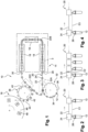
- FIG. 1 a part of a large-scale manufacturing facility 10 for containers made of thermoplastic material such as polyethylene terephthalate or PET.
- the manufacturing facility 10 is here intended to form containers from preforms 12 to be heated.
- the manufacturing installation 10 comprises a station 14 for heating the preforms 12 and a station 16 for forming, here by blowing or stretch-blow molding, the preforms 12 previously heated by said heating station 14.
- the heating station 14 comprises a heating tunnel 18, which is here made in three successive sections.
- the heating tunnel 18 has been shown schematically.
- the heating tunnel 18 defines a heating path which is intended to be traveled by each preform 12.
- such a heating tunnel 18 (respectively each section of the tunnel) is delimited by two side walls (not shown) which form a tunnel. At least one of the walls is provided with heating means, such as infrared lamps (not shown), emitting radiation heating the preforms.
- the heating tunnel 18 can also be equipped with ventilation means making it possible to promote uniform heating of the preforms and making it possible to avoid overheating of certain components of the heating station 14.
- the heating station 14 also includes a conveyor 20 which is intended to transport each preform 12 through the heating tunnel 18.
- the conveyor 20 is here intended to transport the preforms 12 continuously, that is to say without interruption of the movement of the preforms 12.
- the length of the heating tunnel 18 and the power of the heating means are adapted so that the preforms 12 emerge heated to a temperature sufficient for their forming by the forming station 16.
- the conveyor 20 comprises at least one running rail 22 which forms a closed circuit and on which shuttles 24 circulate. Each shuttle 24 is controlled individually in movement, that is to say independently of the other shuttles 24.
- the rail runs across the heating station in an open circuit, the rail also serving upstream or downstream treatment stations.
- Such an arrangement is referred to as "sequential".
- the shuttles 24 and the scroll rail 22 are part of a linear motor.
- the scroll rail 22 comprises a stator which is formed of a series of windings (not shown) which are distributed along the rail 22. Each winding is individually controlled to locally induce a magnetic field independently of the other windings.
- the windings are, for example, controlled by an electronic control unit (not shown) which is programmed appropriately.
- Each shuttle 24 is equipped with at least one permanent magnet which reacts to the magnetic field induced by each winding of the rail 22 by causing the shuttle 24 to move along the rail 22. In addition, each shuttle 24 is guided in movement along the running rail 22.
- the pitch between two windings is sufficiently small to allow the windings of the scrolling rail 22 to be controlled so as to cause the movement of each shuttle 24 independently of the other shuttles 24.
- Such a linear motor is sold, for example, by Beckhoff under the name "XTS".
- XTS WO-A1-2013/143.783 or even WO-A1-2013/143.950 .
- this technology implemented within the framework of the invention makes it possible to move all the shuttles 24 in a row in the same direction of movement along the circuit, here a counterclockwise direction.
- the speed of movement of each shuttle 24 can be controlled individually by an electronic control unit (not shown).
- Each shuttle 24 comprises at least one individual support member for a preform 12.
- each shuttle 24 comprises a single individual support member for a preform 12. In the example shown in figures 2 to 4 , it is a mandrel 26 which is inserted vertically into a neck of the preform 12. Thus, each shuttle 24 is capable of transporting a preform 12.
- the mandrel 26 is for example mounted to slide vertically on the shuttle 24 between a low preform gripping position and a high preform ejection position.
- the sliding is for example controlled by an electric motor or by a cam system.
- the 22 scroll rail can be divided into several sections.
- At least one section called “heating section 22B" of the running rail 22 allows the shuttles 24 to transport the preforms 12 along the heating path.
- the heating section 22B extends from an inlet 28 of the heating tunnel 18 to an outlet 30 of the heating tunnel 18.
- a section called the "loading section 22A" of the running rail 22 is arranged upstream of the inlet 28 of the heating tunnel 18, according to the direction of circulation of the shuttles 24.
- the preforms 12 to be heated are loaded onto the shuttles 24 circulating on this section 22A.
- the shuttles 24 arrive on this loading section 22A "empty” and they leave it loaded with a preform 12 to be heated.
- a section called the "unloading section 22C" of the running rail 22 is interposed between the outlet 30 of the heating tunnel 18 and the loading section 22A, according to the direction of circulation of the shuttles 24.
- the hot preforms 12 are unloaded from shuttles 24 circulating on this unloading section 22C.
- the shuttles 24 arrive on this unloading section 22C each loaded with a hot preform 12 after its passage through the heating tunnel 18 and they leave it "empty".
- the manufacturing installation 10 also comprises an input device 32 for the preforms 12 to be heated, bringing the preforms 12 to be heated to the loading section 22A of the running rail 22 for loading them onto the shuttles 24.
- the input device 32 is capable of bringing, to the loading section 22A, each preform 12 successively, two successive preforms 12 being separated by a determined input pitch according to their direction of movement.
- the input device 32 is formed by a wheel 34 with notches 36.
- the wheel 34 is rotatably mounted around a vertical axis.
- the wheel 34 has at its periphery notches 36, each of which is capable of carrying a preform 12 in association with known means not shown, such as peripheral guide guides.
- Two neighboring notches 36 are circumferentially spaced apart from said determined input pitch.
- the installation 10 also comprises a device 38 for exiting the hot preforms 12 which is capable of transferring the preforms 12 from the unloading section 22C from the scrolling rail 22 to the forming station 16.
- the output device 38 is designed to load the preforms 12 one after the other, two successive preforms 12 being spaced apart by a determined output pitch according to their direction of movement.
- the output device 38 is formed by a wheel 40 equipped at its periphery with a plurality of arms 42.
- Each arm 42 comprises at its free end a support member such as a clamp 44 capable of gripping a preform 12 by its neck.
- the forming station 16 is here formed by a carousel 46 (of which only a part is shown) which carries a plurality of molding units 48 at its periphery.
- the carousel 46 is rotatably mounted so as to move the preforms 12 then the containers during their forming.
- Such a forming station is well known and will therefore not be described in more detail subsequently.
- the circumferential gap between two neighboring molding units 48 is greater than the determined exit pitch of the hot preforms 12.
- the arms 44 are generally pivotally and/or slidably mounted on the wheel 40 to allow the pitch to be changed between two successive preforms 12 during their transport to the forming station 16.
- the preforms 12 are spaced apart by a pitch adapted to the spacing between two molding units 48 during their transfer to the forming station 16.
- a method of controlling the conveyor 20 is now described, making it possible to take full advantage of the energy used by the heating means of the heating tunnel 18.
- the spacing between two successive shuttles 24 is equal to the longitudinal spacing between the two support members of these two shuttles 24, which members are here constituted by the mandrels 26.
- each shuttle 24 passes in coincidence with a notch 36 of the entry device 32 allowing the mandrel 26 to be inserted into the neck of the preform 12 while the latter is still supported by the notch 36.
- the shuttles 24 are controlled so that the spacing between two successive shuttles is reduced relative to said first entry spacing "E1".
- the spacing between two successive shuttles 24 remains reduced relative to said first entry spacing "E1" as long as they are circulating on the heating section 22B.
- the spacing between two successive shuttles 24 remains equal to a second constant spacing "E2", called the heating spacing, which does not change as long as they circulate on the heating section 22B of the running rail 22.
- Each shuttle 24 is more particularly controlled so as to circulate in coincidence with a corresponding support member 44 of the output device 38 to allow the transfer of the preforms 12 from the conveyor 20 to the output device 38.
- the third outlet spacing "E3" is different from the first inlet spacing "E1".
- the third outlet spacing "E3" is greater than the first inlet spacing "E1". Therefore, the third outlet spacing "E3" is also greater than the second heating spacing "E2".
- the second heating gap "E2" is less than the first inlet gap “E1" and the third outlet gap "E3".
- the preforms 12 are here directly transferred from the conveyor 20 to the forming station 16 without interposition of intermediate transport means between the heating station 14 and the forming station 16.
- the hot preforms 12 are directly deposited in the molding units by the shuttles 24.
- This arrangement allows for a very compact manufacturing installation. It also reduces the transfer time between heating the preforms and forming them.
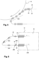
- FIG. 6 We represented at the Figure 6 a second embodiment of the manufacturing installation 10. This installation 10 is similar to that described in the first embodiment shown in Figure 1 . Only the differences with this first embodiment will be therefore described below.
- each shuttle 24 comprises a first member 26A for supporting a first preform 12 and a second member 26B for supporting a second preform 12.
- the shuttle 24 is thus capable of simultaneously carrying two preforms 12.
- Each support member 26A, 26B is for example formed by a mandrel.
- the support members 26A, 26B are mounted to move on the shuttle 24 between an extended position in which the support members 26A, 26B are spaced apart from the first entry step of the preforms in the direction of movement of the shuttle 24, and a close position in which the support members 26A, 26B are brought closer to each other in the direction of movement of the shuttle 24.
- the shuttle 24 comprises an arm 50 defining an orientation axis.
- Each end of said arm 50 comprises one of the support members 26A, 26B.
- the arm 50 is itself pivotally mounted on the shuttle 24 around a vertical main axis between a straight position corresponding to the direction of movement of the shuttle 24, and an oblique position inclined relative to the straight position.
- the pivoting of the arm 50 between its two positions is for example controlled by an actuator (not shown) on board the shuttle 24.
- the shuttles 24 running on the loading section 22A of the running rail 22 are controlled to be spaced apart by a first spacing "E1" which is equal to twice the determined entry pitch of the preforms 12.
- the arm 50 is controlled in its straight position.
- all the support members 26A, 26B, in their extended position are spaced apart by the same pitch as the entry pitch of the preforms 12.
- the arms 50 are controlled towards their oblique position. This allows the shuttles 24 to be controlled so as to be spaced apart by a second spacing "E2" which is much less than the first spacing "E1".
- the shuttles 24 are more particularly controlled so that the preforms 12 are distributed over two rows, as shown in Figure 6
- the preforms 12 of the first row are carried by the transport members 26A arranged at the front of the shuttles 24 while the preforms 12 of the second row are carried by the transport members 26B arranged at the rear of the shuttles 24.
- the arm 50 forms an angle with the direction of movement of the shuttles 24, for example an angle of 45°, so that the preforms 12 of the first row are offset longitudinally between two preforms 12 of the second row.
- the entry pitch of the preforms is equal to the exit pitch of the preforms.
- the shuttles 24 are controlled to be spaced apart from said first spacing "E1" which is equal to twice the determined entry pitch of the preforms 12.
- the arm 50 is controlled in its straight position.
- all the support members 26A, 26B, in their extended position are spaced apart by the same pitch as the exit pitch of the preforms 12.
- the actuator is for example a stand-alone actuator, such as a motor, which is on board the associated shuttle.
- the actuator requires external intervention to be actuated.
- This is for example a cam control device.
- a cam follower is for example on board the shuttle, while a cam path arranged parallel to the circulation rail makes it possible to act on the cam follower to actuate the arm.
- the actuator is capable of being actuated by an actuating member carried by one of the adjacent shuttles.
- a pusher of a shuttle 24 is capable of coming into contact with a pivoting mechanism of an adjacent shuttle 24 to control the pivoting of the arm 50.
- This is for example a cam device or a meshing device.
- the method is not limited to the embodiment shown in the figures.
- a station for processing the preforms and/or final containers could be interposed between the furnace outlet and the unloading section.
- Such an arrangement is particularly advantageous in a so-called "sequential" arrangement of the processing stations, as explained previously.
- the conveyor makes it possible to transport a hollow body from its initial state in the form of a preform, then, after the forming of said preform, into its final state as a finished container.
- control method also makes it possible to modulate the spacing between two shuttles so as to space the preforms of a first entry step on the loading section 22A, a second heating step on the heating section 22B and a third exit step on the unloading section 22C.
Landscapes
- Engineering & Computer Science (AREA)
- Mechanical Engineering (AREA)
- Manufacturing & Machinery (AREA)
- Physics & Mathematics (AREA)
- Thermal Sciences (AREA)
- General Engineering & Computer Science (AREA)
- Geometry (AREA)
- Blow-Moulding Or Thermoforming Of Plastics Or The Like (AREA)
Claims (2)
- Verfahren zur Steuerung eines Förderers (20) für Hohlkörper (12) durch eine Aufheizstation (14) für eine Anlage (10) zur Fertigung von Behältern aus thermoplastischem Material, umfassend:- einen Aufheiztunnel (18), der eine Heizstrecke definiert;- einen Förderer (20), der mindestens eine Laufschiene (22), die einen Kreislauf bildet, und Schlitten (24), die entlang der Schiene (22) umlaufen und dabei mindestens einen Hohlkörper (12) aufnehmen können, umfasst, wobei die Bewegung jedes Schlittens (24) individuell gesteuert wird, wobei die Schiene (22) einen Heizabschnitt (22B) für den Transport der Hohlkörper (12) entlang der Heizstrecke aufweist;- eine Eintrittsvorrichtung (32) für die aufzuheizenden Hohlkörper (12), die die Hohlkörper (12) bis zu einem Beladeabschnitt (22A) der Laufschiene (22) führt, damit sie in die Schlitten (24) geladen werden, wobei zwei aufeinanderfolgende Schlitten (24) auf diesem Beladeabschnitt (22A) mit einem bestimmten ersten Eintrittsabstand (E1) umlaufen;- eine Austrittsvorrichtung (38) für die heißen Hohlkörper (12), die die Hohlkörper (12), die in den Schlitten (24), die auf einem Entladeabschnitt (22C) der Laufschiene (22) umlaufen, aufgenommen sind, zurücknimmt;wobei:die Schlitten (24) mindestens ab ihrem Eintritt in den Heizabschnitt (22B) so gesteuert werden, dass der Abstand zwischen zwei aufeinanderfolgenden Schlitten (24) mit Bezug auf den ersten Eintrittsabstand (E1) verringert wird;wenn die Schlitten (24) in dem Entladeabschnitt (22C) ankommen, sie so gesteuert werden, dass zwei aufeinanderfolgende Schlitten (24) mit einem bestimmten dritten Austrittsabstand (E3) umlaufen;der Abstand zwischen zwei Schlitten (24) verglichen mit dem ersten Eintrittsabstand (E1) verringert bleibt, solange sie in dem Heizabschnitt (22B) umlaufen;der Abstand zwischen zwei aufeinanderfolgenden Schlitten gleich einem konstanten zweiten Abstand (E2) bleibt, solange sie in dem Heizabschnitt (22B) umlaufen;der zweite Heizabstand (E2) kleiner als der erste Eintrittsabstand (E1) und der dritte Austrittsabstand (E3) ist;sich der dritte Austrittsabstand (E3) von dem ersten Eintrittsabstand (E1) unterscheidet.
- Verfahren nach Anspruch 1, dadurch gekennzeichnet, dass der Austrittsabstand (E3) größer als der zweite Heizabstand (E2) ist.
Priority Applications (1)
| Application Number | Priority Date | Filing Date | Title |
|---|---|---|---|
| EP22156922.1A EP4026681B1 (de) | 2015-04-29 | 2016-04-21 | Förderbands für hohlkörper durch eine heizstation |
Applications Claiming Priority (2)
| Application Number | Priority Date | Filing Date | Title |
|---|---|---|---|
| FR1553860A FR3035651B1 (fr) | 2015-04-29 | 2015-04-29 | "procede de commande d'un convoyeur de corps creux a travers une station de chauffage et convoyeur associe" |
| PCT/FR2016/050934 WO2017013317A1 (fr) | 2015-04-29 | 2016-04-21 | Procédé de commande d'un convoyeur de corps creux a travers une station de chauffage et convoyeur associe |
Related Child Applications (2)
| Application Number | Title | Priority Date | Filing Date |
|---|---|---|---|
| EP22156922.1A Division EP4026681B1 (de) | 2015-04-29 | 2016-04-21 | Förderbands für hohlkörper durch eine heizstation |
| EP22156922.1A Division-Into EP4026681B1 (de) | 2015-04-29 | 2016-04-21 | Förderbands für hohlkörper durch eine heizstation |
Publications (3)
| Publication Number | Publication Date |
|---|---|
| EP3288742A1 EP3288742A1 (de) | 2018-03-07 |
| EP3288742B1 EP3288742B1 (de) | 2022-04-06 |
| EP3288742B2 true EP3288742B2 (de) | 2025-04-23 |
Family
ID=54014945
Family Applications (2)
| Application Number | Title | Priority Date | Filing Date |
|---|---|---|---|
| EP22156922.1A Active EP4026681B1 (de) | 2015-04-29 | 2016-04-21 | Förderbands für hohlkörper durch eine heizstation |
| EP16738476.7A Active EP3288742B2 (de) | 2015-04-29 | 2016-04-21 | Verfahren zur steuerung eines förderers für hohlkörper durch eine aufheizstation |
Family Applications Before (1)
| Application Number | Title | Priority Date | Filing Date |
|---|---|---|---|
| EP22156922.1A Active EP4026681B1 (de) | 2015-04-29 | 2016-04-21 | Förderbands für hohlkörper durch eine heizstation |
Country Status (5)
| Country | Link |
|---|---|
| US (1) | US10363697B2 (de) |
| EP (2) | EP4026681B1 (de) |
| CN (1) | CN107530945B (de) |
| FR (1) | FR3035651B1 (de) |
| WO (1) | WO2017013317A1 (de) |
Families Citing this family (15)
| Publication number | Priority date | Publication date | Assignee | Title |
|---|---|---|---|---|
| FR3035651B1 (fr) | 2015-04-29 | 2017-04-21 | Sidel Participations | "procede de commande d'un convoyeur de corps creux a travers une station de chauffage et convoyeur associe" |
| IT201700055174A1 (it) * | 2017-05-22 | 2018-11-22 | Lanfranchi Srl | Macchina stiro-soffiatrice lineare per la produzione di contenitori in materiale plastico |
| DE102017127322A1 (de) * | 2017-11-20 | 2019-05-23 | Khs Gmbh | Vorrichtung und Verfahren zum gruppenweisen Zuführen von Behälter an eine getaktete Behandlungsmaschine |
| FR3088026B1 (fr) | 2018-11-02 | 2020-10-16 | Sidel Participations | Procede de gestion de preformes immobilisees dans une station de chauffage |
| FR3088027B1 (fr) | 2018-11-02 | 2020-10-16 | Sidel Participations | Procede de gestion de preformes immobilisees dans une station de chauffage apres une interruption de production |
| IT202000005350A1 (it) * | 2020-03-12 | 2021-09-12 | Siapi S R L | Metodo e impianto per la produzione di contenitori in plastica |
| DE102020120284A1 (de) * | 2020-07-31 | 2022-02-03 | Krones Aktiengesellschaft | Vorrichtung zur Behandlung von Behälterrohlingen |
| DE102021123764A1 (de) | 2021-09-14 | 2023-03-16 | Khs Gmbh | Vorrichtung zum Herstellen von Behältern aus Vorformlingen aus thermoplastischem Material |
| FR3136187B1 (fr) * | 2022-06-01 | 2024-04-19 | Sidel Participations | Procede de conditionnement thermique de preformes |
| FR3136395B1 (fr) | 2022-06-10 | 2024-07-05 | Sidel Participations | Station de chauffage de preformes comportant des moyens de refroidissement |
| DE102022118647A1 (de) * | 2022-07-26 | 2024-02-01 | Khs Gmbh | Blasformanlagenanordnung sowie Blasformanlage |
| FR3140360B1 (fr) | 2022-09-30 | 2024-08-30 | Sidel Participations | Procede de transfert de preforme sur un convoyeur |
| FR3153088B1 (fr) | 2023-09-14 | 2025-08-22 | Sidel Participations | Dispositif de decontamination de preformes |
| FR3153013B1 (fr) | 2023-09-14 | 2025-08-22 | Sidel Participations | Dispositif de decontamination de preformes |
| DE102024104932A1 (de) * | 2024-02-22 | 2025-08-28 | Khs Gmbh | Verfahren und Vorrichtung zum Herstellen von Behältern aus Vorformlingen aus einem thermoplastischen Material mit hoher Produktionsleistung |
Citations (6)
| Publication number | Priority date | Publication date | Assignee | Title |
|---|---|---|---|---|
| DE4133114A1 (de) † | 1991-10-05 | 1993-04-08 | Michael Rupp | Foerdersystem fuer stueckgut |
| EP0571262A1 (de) † | 1992-05-20 | 1993-11-24 | Sidel | Vorrichtung für die thermische Behandlung von PET-Behältern während der Herstellung |
| WO2001089790A1 (en) † | 2000-05-24 | 2001-11-29 | Uniloy Milacron Inc. | Unrestrained preform carriers for a blow molding machine |
| US20080187616A1 (en) † | 2005-08-29 | 2008-08-07 | Sidel Participations | Transfer Chain for a Preform Heater Intended for a Container Blow-Molding Machine |
| DE102013100627A1 (de) † | 2013-01-22 | 2014-07-24 | Krones Aktiengesellschaft | Verfahren zum betreiben einer behälterbehandlungsanlage und behälterbehandlungsanlage |
| EP2848382A1 (de) † | 2013-09-13 | 2015-03-18 | Krones AG | Behälterbehandlungsanlage mit einem Ofen und einer Blasformvorrichtung mit Individual-Antrieb von Trägern für Preforms |
Family Cites Families (29)
| Publication number | Priority date | Publication date | Assignee | Title |
|---|---|---|---|---|
| US3995990A (en) * | 1974-03-11 | 1976-12-07 | Monsanto Company | Pre-form reheat oven for stretch blow molding machines |
| US4793960A (en) * | 1985-05-14 | 1988-12-27 | Husky Injection Molding Systems Ltd. | Process for preparing hollow plastic articles |
| DE3910293A1 (de) | 1989-03-30 | 1990-10-04 | Bekum Maschf Gmbh | Vorrichtung zum blasformen vorgefertigter vorformlinge |
| EP0387737B1 (de) * | 1989-03-14 | 1993-08-11 | BEKUM Maschinenfabriken GmbH | Verfahren zur Erhitzung von einem Vorrat entnommenen gespritzten Vorformlingen für das anschliessende Aufblasen zu Hohlkörpern in einer Blasform und Vorrichtung zum Blasformen vorgefertigter Vorformlinge |
| TW508300B (en) * | 1994-09-16 | 2002-11-01 | Asb Co Ltd | Injection-stretch-blow moulding method |
| FR2731176B1 (fr) * | 1995-03-02 | 1997-04-30 | Sidel Sa | Installation de fabrication de recipients par soufflage de preformes en matiere plastique |
| US5607706A (en) * | 1995-04-05 | 1997-03-04 | Husky Injection Molding Systems Ltd. | Preconditioning preforms on a reheat blow molding system |
| ES2130006B1 (es) * | 1995-07-10 | 2000-02-16 | Urola S Coop | Maquina moldeadora de preformas por soplado. |
| CH690543A5 (fr) * | 1995-07-19 | 2000-10-13 | Tetra Pak Plastics Ltd Tetra P | Machines pour la fabrication de récipients en matière plastique. |
| CH690095A5 (fr) * | 1995-12-07 | 2000-04-28 | Tetra Pak Plastics Ltd Tetra P | Dispositif de chauffage pour machines de transformation de matières plastiques. |
| JP3775801B2 (ja) * | 1996-09-02 | 2006-05-17 | 日精エー・エス・ビー機械株式会社 | 加熱ブロー成形装置および加熱ブロー成形方法 |
| JP4201223B2 (ja) * | 1998-10-20 | 2008-12-24 | 株式会社フロンティア | 二軸延伸ブロー成形機 |
| DE19906366A1 (de) * | 1999-02-16 | 2000-08-17 | Krupp Corpoplast Masch | Verfahren und Vorrichtung zur Übergabe von Formlingen |
| US20040047941A1 (en) * | 2001-05-24 | 2004-03-11 | Salenbien Leon G. | Blow molding machine having flexible cavitation |
| US7727454B2 (en) * | 2007-06-15 | 2010-06-01 | Sidel Participations | Device for transferring items by means of a group modules having variable spacing |
| EP2052842A1 (de) | 2007-10-23 | 2009-04-29 | Glauco E. Curetti | Verfahren und System zur Herstellung eines Polymerbehälters |
| DE102008042543B4 (de) * | 2008-10-01 | 2013-12-19 | Chumpower Machinery Corp. | Abstandseinstellvorrichtung für eine Blasformmaschine |
| DE102010001184A1 (de) * | 2010-01-25 | 2011-07-28 | Krones Ag, 93073 | Etikettiervorrichtung und -verfahren zum Etikettieren von Kunststoffflaschen in einer Blasform, insbesondere in einer Rotationsmaschine |
| DE102010003350A1 (de) | 2010-03-26 | 2011-09-29 | Krones Ag | Verfahren zum Herstellen von Kunststoffbehältern |
| DE102010018153B4 (de) * | 2010-04-22 | 2023-11-02 | Krones Aktiengesellschaft | Transporteinrichtung und Transportverfahren für Behälterbehandlungsanlage sowie Behälterbehandlungsanlage mit solcher Transporteinrichtung |
| DE102010020724A1 (de) * | 2010-05-17 | 2011-11-17 | Krones Ag | Rotierende Vorrichtung zum Transport von Artikeln |
| CN103124627B (zh) * | 2010-10-08 | 2015-11-25 | 日精Asb机械株式会社 | 喷吹成形装置及喷吹成形方法 |
| DE102010049136A1 (de) * | 2010-10-22 | 2012-04-26 | Krones Aktiengesellschaft | Heizvorrichtung zur Temperierung von Vorformlingen |
| US8996161B2 (en) | 2011-05-19 | 2015-03-31 | Rockwell Automation, Inc. | Controlled architecture for transport systems |
| US8896241B2 (en) | 2011-11-16 | 2014-11-25 | Rockwell Automation Technologies, Inc. | Controlled motion system |
| DE202012013152U1 (de) | 2012-03-27 | 2015-02-11 | Beckhoff Automation Gmbh | Statorvorrichtung für einen Linearmotor und lineares Transportsystem |
| DE102012204916A1 (de) | 2012-03-27 | 2013-10-02 | Beckhoff Automation Gmbh | Statorvorrichtung für einen Linearmotor und lineares Transportsystem |
| ITMI20120991A1 (it) * | 2012-06-07 | 2013-12-08 | Smi Spa | Sistema di distanziamento e trasferimento di oggetti tra stazioni operative |
| FR3035651B1 (fr) | 2015-04-29 | 2017-04-21 | Sidel Participations | "procede de commande d'un convoyeur de corps creux a travers une station de chauffage et convoyeur associe" |
-
2015
- 2015-04-29 FR FR1553860A patent/FR3035651B1/fr not_active Expired - Fee Related
-
2016
- 2016-04-21 EP EP22156922.1A patent/EP4026681B1/de active Active
- 2016-04-21 EP EP16738476.7A patent/EP3288742B2/de active Active
- 2016-04-21 CN CN201680024661.5A patent/CN107530945B/zh active Active
- 2016-04-21 US US15/569,297 patent/US10363697B2/en active Active
- 2016-04-21 WO PCT/FR2016/050934 patent/WO2017013317A1/fr not_active Ceased
Patent Citations (6)
| Publication number | Priority date | Publication date | Assignee | Title |
|---|---|---|---|---|
| DE4133114A1 (de) † | 1991-10-05 | 1993-04-08 | Michael Rupp | Foerdersystem fuer stueckgut |
| EP0571262A1 (de) † | 1992-05-20 | 1993-11-24 | Sidel | Vorrichtung für die thermische Behandlung von PET-Behältern während der Herstellung |
| WO2001089790A1 (en) † | 2000-05-24 | 2001-11-29 | Uniloy Milacron Inc. | Unrestrained preform carriers for a blow molding machine |
| US20080187616A1 (en) † | 2005-08-29 | 2008-08-07 | Sidel Participations | Transfer Chain for a Preform Heater Intended for a Container Blow-Molding Machine |
| DE102013100627A1 (de) † | 2013-01-22 | 2014-07-24 | Krones Aktiengesellschaft | Verfahren zum betreiben einer behälterbehandlungsanlage und behälterbehandlungsanlage |
| EP2848382A1 (de) † | 2013-09-13 | 2015-03-18 | Krones AG | Behälterbehandlungsanlage mit einem Ofen und einer Blasformvorrichtung mit Individual-Antrieb von Trägern für Preforms |
Also Published As
| Publication number | Publication date |
|---|---|
| US10363697B2 (en) | 2019-07-30 |
| US20180117825A1 (en) | 2018-05-03 |
| WO2017013317A1 (fr) | 2017-01-26 |
| EP3288742A1 (de) | 2018-03-07 |
| CN107530945B (zh) | 2020-11-17 |
| EP4026681A1 (de) | 2022-07-13 |
| FR3035651A1 (fr) | 2016-11-04 |
| EP3288742B1 (de) | 2022-04-06 |
| FR3035651B1 (fr) | 2017-04-21 |
| CN107530945A (zh) | 2018-01-02 |
| EP4026681B1 (de) | 2025-05-28 |
Similar Documents
| Publication | Publication Date | Title |
|---|---|---|
| EP3288742B2 (de) | Verfahren zur steuerung eines förderers für hohlkörper durch eine aufheizstation | |
| EP2392442B2 (de) | Ofen für die Wärmebehandlung von Vorformligen und Steuerungsverfahren einer Abkühlvorrichtung mit Hilfe von Luft, die in einem solchen Ofen eingebaut ist | |
| EP3239079B1 (de) | Förderanlage für hohlkörper, die ein förderband zur verteilung und satelliteneinheiten zur bearbeitung umfasst | |
| FR2941442A1 (fr) | Installation de production de recipients comportant une roue de transfert a pas variable. | |
| EP4076900A1 (de) | Verfahren zur winkelindexierung einer vorform | |
| WO2020089556A1 (fr) | Procede et dispositif de gestion de preformes immobilisees dans une station de chauffage | |
| EP3873719B1 (de) | Verfahren zur verwaltung von in einer heizstation immobilisierten vorformen nach einer produktionsunterbrechung | |
| EP3256408B1 (de) | Anlage zur behandlung von behältern mit einer behandlungsstation und vorrichtung zum seitlichen transfer von behältern | |
| EP3843974B2 (de) | Verfahren zur individuellen messung der temperatur einer vorform | |
| EP3079879B2 (de) | Vorrichtung zur seriellen behandlung von hohlkörpern mit einer durch ein elektrisches stellglied gleitend gesteuerten behandlungsstange und behandlungsverfahren | |
| FR3027886A1 (fr) | "dispositif de transport de preformes dans un four de conditionnement thermique" | |
| EP4286137B1 (de) | Verfahren zur thermischen konditionierung von vorformlingen | |
| FR3035650A1 (fr) | "station de traitement equipee d'un convoyeur de corps creux comportant un embranchement de bifurcation" | |
| FR3082139A1 (fr) | Installation de production de recipients a arret d'urgence selectif | |
| EP4249212B1 (de) | Vorformheizstation mit mitteln zum drehen von vorformen mit einer heizzone | |
| FR3086574A1 (fr) | Installation de fabrication de corps creux comportant un organe de regulation de la circulation des corps creux mu par un moteur electrique lineaire |
Legal Events
| Date | Code | Title | Description |
|---|---|---|---|
| STAA | Information on the status of an ep patent application or granted ep patent |
Free format text: STATUS: THE INTERNATIONAL PUBLICATION HAS BEEN MADE |
|
| PUAI | Public reference made under article 153(3) epc to a published international application that has entered the european phase |
Free format text: ORIGINAL CODE: 0009012 |
|
| STAA | Information on the status of an ep patent application or granted ep patent |
Free format text: STATUS: REQUEST FOR EXAMINATION WAS MADE |
|
| 17P | Request for examination filed |
Effective date: 20171025 |
|
| AK | Designated contracting states |
Kind code of ref document: A1 Designated state(s): AL AT BE BG CH CY CZ DE DK EE ES FI FR GB GR HR HU IE IS IT LI LT LU LV MC MK MT NL NO PL PT RO RS SE SI SK SM TR |
|
| AX | Request for extension of the european patent |
Extension state: BA ME |
|
| DAV | Request for validation of the european patent (deleted) | ||
| DAX | Request for extension of the european patent (deleted) | ||
| STAA | Information on the status of an ep patent application or granted ep patent |
Free format text: STATUS: EXAMINATION IS IN PROGRESS |
|
| 17Q | First examination report despatched |
Effective date: 20201222 |
|
| REG | Reference to a national code |
Ref country code: DE Ref legal event code: R079 Ref document number: 602016070771 Country of ref document: DE Free format text: PREVIOUS MAIN CLASS: B29C0049420000 Ipc: F27B0009240000 |
|
| GRAP | Despatch of communication of intention to grant a patent |
Free format text: ORIGINAL CODE: EPIDOSNIGR1 |
|
| STAA | Information on the status of an ep patent application or granted ep patent |
Free format text: STATUS: GRANT OF PATENT IS INTENDED |
|
| INTG | Intention to grant announced |
Effective date: 20220107 |
|
| RIC1 | Information provided on ipc code assigned before grant |
Ipc: B29L 31/00 20060101ALN20211217BHEP Ipc: B29K 67/00 20060101ALN20211217BHEP Ipc: B65G 54/02 20060101ALI20211217BHEP Ipc: B29C 49/68 20060101ALI20211217BHEP Ipc: B29C 49/42 20060101ALI20211217BHEP Ipc: F27B 9/24 20060101AFI20211217BHEP |
|
| GRAS | Grant fee paid |
Free format text: ORIGINAL CODE: EPIDOSNIGR3 |
|
| GRAA | (expected) grant |
Free format text: ORIGINAL CODE: 0009210 |
|
| STAA | Information on the status of an ep patent application or granted ep patent |
Free format text: STATUS: THE PATENT HAS BEEN GRANTED |
|
| AK | Designated contracting states |
Kind code of ref document: B1 Designated state(s): AL AT BE BG CH CY CZ DE DK EE ES FI FR GB GR HR HU IE IS IT LI LT LU LV MC MK MT NL NO PL PT RO RS SE SI SK SM TR |
|
| REG | Reference to a national code |
Ref country code: GB Ref legal event code: FG4D Free format text: NOT ENGLISH |
|
| REG | Reference to a national code |
Ref country code: CH Ref legal event code: EP |
|
| REG | Reference to a national code |
Ref country code: AT Ref legal event code: REF Ref document number: 1481709 Country of ref document: AT Kind code of ref document: T Effective date: 20220415 |
|
| REG | Reference to a national code |
Ref country code: IE Ref legal event code: FG4D Free format text: LANGUAGE OF EP DOCUMENT: FRENCH |
|
| REG | Reference to a national code |
Ref country code: DE Ref legal event code: R096 Ref document number: 602016070771 Country of ref document: DE |
|
| REG | Reference to a national code |
Ref country code: LT Ref legal event code: MG9D |
|
| REG | Reference to a national code |
Ref country code: NL Ref legal event code: MP Effective date: 20220406 |
|
| REG | Reference to a national code |
Ref country code: AT Ref legal event code: MK05 Ref document number: 1481709 Country of ref document: AT Kind code of ref document: T Effective date: 20220406 |
|
| PG25 | Lapsed in a contracting state [announced via postgrant information from national office to epo] |
Ref country code: NL Free format text: LAPSE BECAUSE OF FAILURE TO SUBMIT A TRANSLATION OF THE DESCRIPTION OR TO PAY THE FEE WITHIN THE PRESCRIBED TIME-LIMIT Effective date: 20220406 |
|
| PG25 | Lapsed in a contracting state [announced via postgrant information from national office to epo] |
Ref country code: SE Free format text: LAPSE BECAUSE OF FAILURE TO SUBMIT A TRANSLATION OF THE DESCRIPTION OR TO PAY THE FEE WITHIN THE PRESCRIBED TIME-LIMIT Effective date: 20220406 Ref country code: PT Free format text: LAPSE BECAUSE OF FAILURE TO SUBMIT A TRANSLATION OF THE DESCRIPTION OR TO PAY THE FEE WITHIN THE PRESCRIBED TIME-LIMIT Effective date: 20220808 Ref country code: NO Free format text: LAPSE BECAUSE OF FAILURE TO SUBMIT A TRANSLATION OF THE DESCRIPTION OR TO PAY THE FEE WITHIN THE PRESCRIBED TIME-LIMIT Effective date: 20220706 Ref country code: LT Free format text: LAPSE BECAUSE OF FAILURE TO SUBMIT A TRANSLATION OF THE DESCRIPTION OR TO PAY THE FEE WITHIN THE PRESCRIBED TIME-LIMIT Effective date: 20220406 Ref country code: HR Free format text: LAPSE BECAUSE OF FAILURE TO SUBMIT A TRANSLATION OF THE DESCRIPTION OR TO PAY THE FEE WITHIN THE PRESCRIBED TIME-LIMIT Effective date: 20220406 Ref country code: GR Free format text: LAPSE BECAUSE OF FAILURE TO SUBMIT A TRANSLATION OF THE DESCRIPTION OR TO PAY THE FEE WITHIN THE PRESCRIBED TIME-LIMIT Effective date: 20220707 Ref country code: FI Free format text: LAPSE BECAUSE OF FAILURE TO SUBMIT A TRANSLATION OF THE DESCRIPTION OR TO PAY THE FEE WITHIN THE PRESCRIBED TIME-LIMIT Effective date: 20220406 Ref country code: ES Free format text: LAPSE BECAUSE OF FAILURE TO SUBMIT A TRANSLATION OF THE DESCRIPTION OR TO PAY THE FEE WITHIN THE PRESCRIBED TIME-LIMIT Effective date: 20220406 Ref country code: BG Free format text: LAPSE BECAUSE OF FAILURE TO SUBMIT A TRANSLATION OF THE DESCRIPTION OR TO PAY THE FEE WITHIN THE PRESCRIBED TIME-LIMIT Effective date: 20220706 Ref country code: AT Free format text: LAPSE BECAUSE OF FAILURE TO SUBMIT A TRANSLATION OF THE DESCRIPTION OR TO PAY THE FEE WITHIN THE PRESCRIBED TIME-LIMIT Effective date: 20220406 |
|
| PG25 | Lapsed in a contracting state [announced via postgrant information from national office to epo] |
Ref country code: RS Free format text: LAPSE BECAUSE OF FAILURE TO SUBMIT A TRANSLATION OF THE DESCRIPTION OR TO PAY THE FEE WITHIN THE PRESCRIBED TIME-LIMIT Effective date: 20220406 Ref country code: PL Free format text: LAPSE BECAUSE OF FAILURE TO SUBMIT A TRANSLATION OF THE DESCRIPTION OR TO PAY THE FEE WITHIN THE PRESCRIBED TIME-LIMIT Effective date: 20220406 Ref country code: LV Free format text: LAPSE BECAUSE OF FAILURE TO SUBMIT A TRANSLATION OF THE DESCRIPTION OR TO PAY THE FEE WITHIN THE PRESCRIBED TIME-LIMIT Effective date: 20220406 Ref country code: IS Free format text: LAPSE BECAUSE OF FAILURE TO SUBMIT A TRANSLATION OF THE DESCRIPTION OR TO PAY THE FEE WITHIN THE PRESCRIBED TIME-LIMIT Effective date: 20220806 |
|
| REG | Reference to a national code |
Ref country code: CH Ref legal event code: PL |
|
| REG | Reference to a national code |
Ref country code: BE Ref legal event code: MM Effective date: 20220430 |
|
| REG | Reference to a national code |
Ref country code: DE Ref legal event code: R026 Ref document number: 602016070771 Country of ref document: DE |
|
| PLBI | Opposition filed |
Free format text: ORIGINAL CODE: 0009260 |
|
| PLAX | Notice of opposition and request to file observation + time limit sent |
Free format text: ORIGINAL CODE: EPIDOSNOBS2 |
|
| PG25 | Lapsed in a contracting state [announced via postgrant information from national office to epo] |
Ref country code: SM Free format text: LAPSE BECAUSE OF FAILURE TO SUBMIT A TRANSLATION OF THE DESCRIPTION OR TO PAY THE FEE WITHIN THE PRESCRIBED TIME-LIMIT Effective date: 20220406 Ref country code: SK Free format text: LAPSE BECAUSE OF FAILURE TO SUBMIT A TRANSLATION OF THE DESCRIPTION OR TO PAY THE FEE WITHIN THE PRESCRIBED TIME-LIMIT Effective date: 20220406 Ref country code: RO Free format text: LAPSE BECAUSE OF FAILURE TO SUBMIT A TRANSLATION OF THE DESCRIPTION OR TO PAY THE FEE WITHIN THE PRESCRIBED TIME-LIMIT Effective date: 20220406 Ref country code: MC Free format text: LAPSE BECAUSE OF FAILURE TO SUBMIT A TRANSLATION OF THE DESCRIPTION OR TO PAY THE FEE WITHIN THE PRESCRIBED TIME-LIMIT Effective date: 20220406 Ref country code: LU Free format text: LAPSE BECAUSE OF NON-PAYMENT OF DUE FEES Effective date: 20220421 Ref country code: LI Free format text: LAPSE BECAUSE OF NON-PAYMENT OF DUE FEES Effective date: 20220430 Ref country code: EE Free format text: LAPSE BECAUSE OF FAILURE TO SUBMIT A TRANSLATION OF THE DESCRIPTION OR TO PAY THE FEE WITHIN THE PRESCRIBED TIME-LIMIT Effective date: 20220406 Ref country code: DK Free format text: LAPSE BECAUSE OF FAILURE TO SUBMIT A TRANSLATION OF THE DESCRIPTION OR TO PAY THE FEE WITHIN THE PRESCRIBED TIME-LIMIT Effective date: 20220406 Ref country code: CZ Free format text: LAPSE BECAUSE OF FAILURE TO SUBMIT A TRANSLATION OF THE DESCRIPTION OR TO PAY THE FEE WITHIN THE PRESCRIBED TIME-LIMIT Effective date: 20220406 Ref country code: CH Free format text: LAPSE BECAUSE OF NON-PAYMENT OF DUE FEES Effective date: 20220430 |
|
| 26 | Opposition filed |
Opponent name: KRONES AG Effective date: 20230105 |
|
| PG25 | Lapsed in a contracting state [announced via postgrant information from national office to epo] |
Ref country code: BE Free format text: LAPSE BECAUSE OF NON-PAYMENT OF DUE FEES Effective date: 20220430 |
|
| GBPC | Gb: european patent ceased through non-payment of renewal fee |
Effective date: 20220706 |
|
| PG25 | Lapsed in a contracting state [announced via postgrant information from national office to epo] |
Ref country code: AL Free format text: LAPSE BECAUSE OF FAILURE TO SUBMIT A TRANSLATION OF THE DESCRIPTION OR TO PAY THE FEE WITHIN THE PRESCRIBED TIME-LIMIT Effective date: 20220406 |
|
| PG25 | Lapsed in a contracting state [announced via postgrant information from national office to epo] |
Ref country code: IE Free format text: LAPSE BECAUSE OF NON-PAYMENT OF DUE FEES Effective date: 20220421 |
|
| PLBB | Reply of patent proprietor to notice(s) of opposition received |
Free format text: ORIGINAL CODE: EPIDOSNOBS3 |
|
| PG25 | Lapsed in a contracting state [announced via postgrant information from national office to epo] |
Ref country code: SI Free format text: LAPSE BECAUSE OF FAILURE TO SUBMIT A TRANSLATION OF THE DESCRIPTION OR TO PAY THE FEE WITHIN THE PRESCRIBED TIME-LIMIT Effective date: 20220406 Ref country code: GB Free format text: LAPSE BECAUSE OF NON-PAYMENT OF DUE FEES Effective date: 20220706 |
|
| P01 | Opt-out of the competence of the unified patent court (upc) registered |
Effective date: 20230424 |
|
| PG25 | Lapsed in a contracting state [announced via postgrant information from national office to epo] |
Ref country code: HU Free format text: LAPSE BECAUSE OF FAILURE TO SUBMIT A TRANSLATION OF THE DESCRIPTION OR TO PAY THE FEE WITHIN THE PRESCRIBED TIME-LIMIT; INVALID AB INITIO Effective date: 20160421 |
|
| PG25 | Lapsed in a contracting state [announced via postgrant information from national office to epo] |
Ref country code: MK Free format text: LAPSE BECAUSE OF FAILURE TO SUBMIT A TRANSLATION OF THE DESCRIPTION OR TO PAY THE FEE WITHIN THE PRESCRIBED TIME-LIMIT Effective date: 20220406 Ref country code: CY Free format text: LAPSE BECAUSE OF FAILURE TO SUBMIT A TRANSLATION OF THE DESCRIPTION OR TO PAY THE FEE WITHIN THE PRESCRIBED TIME-LIMIT Effective date: 20220406 |
|
| PG25 | Lapsed in a contracting state [announced via postgrant information from national office to epo] |
Ref country code: MT Free format text: LAPSE BECAUSE OF FAILURE TO SUBMIT A TRANSLATION OF THE DESCRIPTION OR TO PAY THE FEE WITHIN THE PRESCRIBED TIME-LIMIT Effective date: 20220406 |
|
| PG25 | Lapsed in a contracting state [announced via postgrant information from national office to epo] |
Ref country code: BG Free format text: LAPSE BECAUSE OF FAILURE TO SUBMIT A TRANSLATION OF THE DESCRIPTION OR TO PAY THE FEE WITHIN THE PRESCRIBED TIME-LIMIT Effective date: 20220406 |
|
| PG25 | Lapsed in a contracting state [announced via postgrant information from national office to epo] |
Ref country code: BG Free format text: LAPSE BECAUSE OF FAILURE TO SUBMIT A TRANSLATION OF THE DESCRIPTION OR TO PAY THE FEE WITHIN THE PRESCRIBED TIME-LIMIT Effective date: 20220406 |
|
| PUAH | Patent maintained in amended form |
Free format text: ORIGINAL CODE: 0009272 |
|
| STAA | Information on the status of an ep patent application or granted ep patent |
Free format text: STATUS: PATENT MAINTAINED AS AMENDED |
|
| 27A | Patent maintained in amended form |
Effective date: 20250423 |
|
| AK | Designated contracting states |
Kind code of ref document: B2 Designated state(s): AL AT BE BG CH CY CZ DE DK EE ES FI FR GB GR HR HU IE IS IT LI LT LU LV MC MK MT NL NO PL PT RO RS SE SI SK SM TR |
|
| REG | Reference to a national code |
Ref country code: DE Ref legal event code: R102 Ref document number: 602016070771 Country of ref document: DE |
|
| PGFP | Annual fee paid to national office [announced via postgrant information from national office to epo] |
Ref country code: FR Payment date: 20250319 Year of fee payment: 10 |
|
| PGFP | Annual fee paid to national office [announced via postgrant information from national office to epo] |
Ref country code: IT Payment date: 20250319 Year of fee payment: 10 |
|
| PGFP | Annual fee paid to national office [announced via postgrant information from national office to epo] |
Ref country code: DE Payment date: 20250319 Year of fee payment: 10 |
|
| PG25 | Lapsed in a contracting state [announced via postgrant information from national office to epo] |
Ref country code: TR Free format text: LAPSE BECAUSE OF FAILURE TO SUBMIT A TRANSLATION OF THE DESCRIPTION OR TO PAY THE FEE WITHIN THE PRESCRIBED TIME-LIMIT Effective date: 20220406 |