EP3802056B1 - Installation for producing containers, with selective emergency stop - Google Patents
Installation for producing containers, with selective emergency stop Download PDFInfo
- Publication number
- EP3802056B1 EP3802056B1 EP19737853.2A EP19737853A EP3802056B1 EP 3802056 B1 EP3802056 B1 EP 3802056B1 EP 19737853 A EP19737853 A EP 19737853A EP 3802056 B1 EP3802056 B1 EP 3802056B1
- Authority
- EP
- European Patent Office
- Prior art keywords
- drive means
- main
- auxiliary
- blanks
- unit
- Prior art date
- Legal status (The legal status is an assumption and is not a legal conclusion. Google has not performed a legal analysis and makes no representation as to the accuracy of the status listed.)
- Active
Links
- 238000009434 installation Methods 0.000 title claims description 43
- 238000012546 transfer Methods 0.000 claims description 43
- 238000011144 upstream manufacturing Methods 0.000 claims description 42
- 239000000463 material Substances 0.000 claims description 8
- 238000000034 method Methods 0.000 claims description 8
- 239000004033 plastic Substances 0.000 claims description 4
- 229920003023 plastic Polymers 0.000 claims description 4
- 238000012545 processing Methods 0.000 description 54
- 238000004519 manufacturing process Methods 0.000 description 15
- 239000004698 Polyethylene Substances 0.000 description 6
- 230000007547 defect Effects 0.000 description 6
- 230000005855 radiation Effects 0.000 description 5
- 230000001360 synchronised effect Effects 0.000 description 5
- 238000012423 maintenance Methods 0.000 description 4
- 229920000139 polyethylene terephthalate Polymers 0.000 description 4
- 239000005020 polyethylene terephthalate Substances 0.000 description 4
- 238000000071 blow moulding Methods 0.000 description 3
- 229910052736 halogen Inorganic materials 0.000 description 3
- 150000002367 halogens Chemical class 0.000 description 3
- 101100536354 Drosophila melanogaster tant gene Proteins 0.000 description 2
- 230000003750 conditioning effect Effects 0.000 description 2
- 230000008878 coupling Effects 0.000 description 2
- 238000010168 coupling process Methods 0.000 description 2
- 238000005859 coupling reaction Methods 0.000 description 2
- 238000005202 decontamination Methods 0.000 description 2
- 230000003588 decontaminative effect Effects 0.000 description 2
- 239000012530 fluid Substances 0.000 description 2
- 238000010438 heat treatment Methods 0.000 description 2
- 230000007246 mechanism Effects 0.000 description 2
- QSHDDOUJBYECFT-UHFFFAOYSA-N mercury Chemical compound [Hg] QSHDDOUJBYECFT-UHFFFAOYSA-N 0.000 description 2
- 210000000056 organ Anatomy 0.000 description 2
- 230000003466 anti-cipated effect Effects 0.000 description 1
- 230000000903 blocking effect Effects 0.000 description 1
- 238000007664 blowing Methods 0.000 description 1
- 125000004122 cyclic group Chemical group 0.000 description 1
- 230000009849 deactivation Effects 0.000 description 1
- 230000001419 dependent effect Effects 0.000 description 1
- 238000005265 energy consumption Methods 0.000 description 1
- 230000009477 glass transition Effects 0.000 description 1
- 238000002347 injection Methods 0.000 description 1
- 239000007924 injection Substances 0.000 description 1
- 238000001746 injection moulding Methods 0.000 description 1
- 230000002452 interceptive effect Effects 0.000 description 1
- 238000002372 labelling Methods 0.000 description 1
- 238000002844 melting Methods 0.000 description 1
- 230000008018 melting Effects 0.000 description 1
- 230000002093 peripheral effect Effects 0.000 description 1
- -1 polyethylene terephthalate Polymers 0.000 description 1
- 238000007781 pre-processing Methods 0.000 description 1
- 238000002203 pretreatment Methods 0.000 description 1
- 230000007420 reactivation Effects 0.000 description 1
- 230000009467 reduction Effects 0.000 description 1
- 238000013519 translation Methods 0.000 description 1
Images


Classifications
-
- B—PERFORMING OPERATIONS; TRANSPORTING
- B29—WORKING OF PLASTICS; WORKING OF SUBSTANCES IN A PLASTIC STATE IN GENERAL
- B29C—SHAPING OR JOINING OF PLASTICS; SHAPING OF MATERIAL IN A PLASTIC STATE, NOT OTHERWISE PROVIDED FOR; AFTER-TREATMENT OF THE SHAPED PRODUCTS, e.g. REPAIRING
- B29C49/00—Blow-moulding, i.e. blowing a preform or parison to a desired shape within a mould; Apparatus therefor
- B29C49/02—Combined blow-moulding and manufacture of the preform or the parison
- B29C49/06—Injection blow-moulding
-
- B—PERFORMING OPERATIONS; TRANSPORTING
- B29—WORKING OF PLASTICS; WORKING OF SUBSTANCES IN A PLASTIC STATE IN GENERAL
- B29C—SHAPING OR JOINING OF PLASTICS; SHAPING OF MATERIAL IN A PLASTIC STATE, NOT OTHERWISE PROVIDED FOR; AFTER-TREATMENT OF THE SHAPED PRODUCTS, e.g. REPAIRING
- B29C49/00—Blow-moulding, i.e. blowing a preform or parison to a desired shape within a mould; Apparatus therefor
- B29C49/28—Blow-moulding apparatus
- B29C49/30—Blow-moulding apparatus having movable moulds or mould parts
- B29C49/36—Blow-moulding apparatus having movable moulds or mould parts rotatable about one axis
-
- B—PERFORMING OPERATIONS; TRANSPORTING
- B29—WORKING OF PLASTICS; WORKING OF SUBSTANCES IN A PLASTIC STATE IN GENERAL
- B29C—SHAPING OR JOINING OF PLASTICS; SHAPING OF MATERIAL IN A PLASTIC STATE, NOT OTHERWISE PROVIDED FOR; AFTER-TREATMENT OF THE SHAPED PRODUCTS, e.g. REPAIRING
- B29C49/00—Blow-moulding, i.e. blowing a preform or parison to a desired shape within a mould; Apparatus therefor
- B29C49/42—Component parts, details or accessories; Auxiliary operations
- B29C49/4205—Handling means, e.g. transfer, loading or discharging means
-
- B—PERFORMING OPERATIONS; TRANSPORTING
- B29—WORKING OF PLASTICS; WORKING OF SUBSTANCES IN A PLASTIC STATE IN GENERAL
- B29C—SHAPING OR JOINING OF PLASTICS; SHAPING OF MATERIAL IN A PLASTIC STATE, NOT OTHERWISE PROVIDED FOR; AFTER-TREATMENT OF THE SHAPED PRODUCTS, e.g. REPAIRING
- B29C49/00—Blow-moulding, i.e. blowing a preform or parison to a desired shape within a mould; Apparatus therefor
- B29C49/42—Component parts, details or accessories; Auxiliary operations
- B29C49/4236—Drive means
-
- B—PERFORMING OPERATIONS; TRANSPORTING
- B29—WORKING OF PLASTICS; WORKING OF SUBSTANCES IN A PLASTIC STATE IN GENERAL
- B29C—SHAPING OR JOINING OF PLASTICS; SHAPING OF MATERIAL IN A PLASTIC STATE, NOT OTHERWISE PROVIDED FOR; AFTER-TREATMENT OF THE SHAPED PRODUCTS, e.g. REPAIRING
- B29C49/00—Blow-moulding, i.e. blowing a preform or parison to a desired shape within a mould; Apparatus therefor
- B29C49/42—Component parts, details or accessories; Auxiliary operations
- B29C49/64—Heating or cooling preforms, parisons or blown articles
- B29C49/6409—Thermal conditioning of preforms
- B29C49/6418—Heating of preforms
-
- B—PERFORMING OPERATIONS; TRANSPORTING
- B29—WORKING OF PLASTICS; WORKING OF SUBSTANCES IN A PLASTIC STATE IN GENERAL
- B29C—SHAPING OR JOINING OF PLASTICS; SHAPING OF MATERIAL IN A PLASTIC STATE, NOT OTHERWISE PROVIDED FOR; AFTER-TREATMENT OF THE SHAPED PRODUCTS, e.g. REPAIRING
- B29C49/00—Blow-moulding, i.e. blowing a preform or parison to a desired shape within a mould; Apparatus therefor
- B29C49/42—Component parts, details or accessories; Auxiliary operations
- B29C49/78—Measuring, controlling or regulating
-
- B—PERFORMING OPERATIONS; TRANSPORTING
- B29—WORKING OF PLASTICS; WORKING OF SUBSTANCES IN A PLASTIC STATE IN GENERAL
- B29C—SHAPING OR JOINING OF PLASTICS; SHAPING OF MATERIAL IN A PLASTIC STATE, NOT OTHERWISE PROVIDED FOR; AFTER-TREATMENT OF THE SHAPED PRODUCTS, e.g. REPAIRING
- B29C49/00—Blow-moulding, i.e. blowing a preform or parison to a desired shape within a mould; Apparatus therefor
- B29C49/02—Combined blow-moulding and manufacture of the preform or the parison
- B29C2049/023—Combined blow-moulding and manufacture of the preform or the parison using inherent heat of the preform, i.e. 1 step blow moulding
-
- B—PERFORMING OPERATIONS; TRANSPORTING
- B29—WORKING OF PLASTICS; WORKING OF SUBSTANCES IN A PLASTIC STATE IN GENERAL
- B29C—SHAPING OR JOINING OF PLASTICS; SHAPING OF MATERIAL IN A PLASTIC STATE, NOT OTHERWISE PROVIDED FOR; AFTER-TREATMENT OF THE SHAPED PRODUCTS, e.g. REPAIRING
- B29C49/00—Blow-moulding, i.e. blowing a preform or parison to a desired shape within a mould; Apparatus therefor
- B29C49/42—Component parts, details or accessories; Auxiliary operations
- B29C49/78—Measuring, controlling or regulating
- B29C2049/7878—Preform or article handling, e.g. flow from station to station
-
- B—PERFORMING OPERATIONS; TRANSPORTING
- B29—WORKING OF PLASTICS; WORKING OF SUBSTANCES IN A PLASTIC STATE IN GENERAL
- B29C—SHAPING OR JOINING OF PLASTICS; SHAPING OF MATERIAL IN A PLASTIC STATE, NOT OTHERWISE PROVIDED FOR; AFTER-TREATMENT OF THE SHAPED PRODUCTS, e.g. REPAIRING
- B29C49/00—Blow-moulding, i.e. blowing a preform or parison to a desired shape within a mould; Apparatus therefor
- B29C49/42—Component parts, details or accessories; Auxiliary operations
- B29C49/78—Measuring, controlling or regulating
- B29C2049/788—Controller type or interface
- B29C2049/7882—Control interface, e.g. display
-
- B—PERFORMING OPERATIONS; TRANSPORTING
- B29—WORKING OF PLASTICS; WORKING OF SUBSTANCES IN A PLASTIC STATE IN GENERAL
- B29C—SHAPING OR JOINING OF PLASTICS; SHAPING OF MATERIAL IN A PLASTIC STATE, NOT OTHERWISE PROVIDED FOR; AFTER-TREATMENT OF THE SHAPED PRODUCTS, e.g. REPAIRING
- B29C49/00—Blow-moulding, i.e. blowing a preform or parison to a desired shape within a mould; Apparatus therefor
- B29C49/28—Blow-moulding apparatus
- B29C49/28004—Blow-moulding apparatus designed for easy access by operator
-
- B—PERFORMING OPERATIONS; TRANSPORTING
- B29—WORKING OF PLASTICS; WORKING OF SUBSTANCES IN A PLASTIC STATE IN GENERAL
- B29C—SHAPING OR JOINING OF PLASTICS; SHAPING OF MATERIAL IN A PLASTIC STATE, NOT OTHERWISE PROVIDED FOR; AFTER-TREATMENT OF THE SHAPED PRODUCTS, e.g. REPAIRING
- B29C49/00—Blow-moulding, i.e. blowing a preform or parison to a desired shape within a mould; Apparatus therefor
- B29C49/42—Component parts, details or accessories; Auxiliary operations
- B29C49/4205—Handling means, e.g. transfer, loading or discharging means
- B29C49/42073—Grippers
-
- B—PERFORMING OPERATIONS; TRANSPORTING
- B29—WORKING OF PLASTICS; WORKING OF SUBSTANCES IN A PLASTIC STATE IN GENERAL
- B29C—SHAPING OR JOINING OF PLASTICS; SHAPING OF MATERIAL IN A PLASTIC STATE, NOT OTHERWISE PROVIDED FOR; AFTER-TREATMENT OF THE SHAPED PRODUCTS, e.g. REPAIRING
- B29C49/00—Blow-moulding, i.e. blowing a preform or parison to a desired shape within a mould; Apparatus therefor
- B29C49/42—Component parts, details or accessories; Auxiliary operations
- B29C49/4205—Handling means, e.g. transfer, loading or discharging means
- B29C49/42093—Transporting apparatus, e.g. slides, wheels or conveyors
- B29C49/42095—Rotating wheels or stars
-
- B—PERFORMING OPERATIONS; TRANSPORTING
- B29—WORKING OF PLASTICS; WORKING OF SUBSTANCES IN A PLASTIC STATE IN GENERAL
- B29C—SHAPING OR JOINING OF PLASTICS; SHAPING OF MATERIAL IN A PLASTIC STATE, NOT OTHERWISE PROVIDED FOR; AFTER-TREATMENT OF THE SHAPED PRODUCTS, e.g. REPAIRING
- B29C49/00—Blow-moulding, i.e. blowing a preform or parison to a desired shape within a mould; Apparatus therefor
- B29C49/42—Component parts, details or accessories; Auxiliary operations
- B29C49/4205—Handling means, e.g. transfer, loading or discharging means
- B29C49/42093—Transporting apparatus, e.g. slides, wheels or conveyors
- B29C49/42101—Conveyors, e.g. flat conveyor or clamping between two bands
-
- B—PERFORMING OPERATIONS; TRANSPORTING
- B29—WORKING OF PLASTICS; WORKING OF SUBSTANCES IN A PLASTIC STATE IN GENERAL
- B29C—SHAPING OR JOINING OF PLASTICS; SHAPING OF MATERIAL IN A PLASTIC STATE, NOT OTHERWISE PROVIDED FOR; AFTER-TREATMENT OF THE SHAPED PRODUCTS, e.g. REPAIRING
- B29C49/00—Blow-moulding, i.e. blowing a preform or parison to a desired shape within a mould; Apparatus therefor
- B29C49/42—Component parts, details or accessories; Auxiliary operations
- B29C49/4236—Drive means
- B29C49/42362—Electric drive means, e.g. servomotors
-
- B—PERFORMING OPERATIONS; TRANSPORTING
- B29—WORKING OF PLASTICS; WORKING OF SUBSTANCES IN A PLASTIC STATE IN GENERAL
- B29C—SHAPING OR JOINING OF PLASTICS; SHAPING OF MATERIAL IN A PLASTIC STATE, NOT OTHERWISE PROVIDED FOR; AFTER-TREATMENT OF THE SHAPED PRODUCTS, e.g. REPAIRING
- B29C49/00—Blow-moulding, i.e. blowing a preform or parison to a desired shape within a mould; Apparatus therefor
- B29C49/42—Component parts, details or accessories; Auxiliary operations
- B29C49/42378—Handling malfunction
- B29C49/4238—Ejecting defective preforms or products
Definitions
- the invention relates to the production of containers from blanks made of plastic material (in particular PET). It relates, more particularly, to an installation for producing receptacles and a method for controlling such an installation.
- a receptacle production installation conventionally comprises a receptacle forming unit, a unit for pre-treatment (e.g. heat) of the blanks, and an auxiliary device for transferring the blanks from the processing unit to the processing unit. forming.
- the forming unit comprises, in known manner, a main conveyor (e.g. a carousel), which defines a forming path (typically circular), a plurality of forming stations carried by the main conveyor and each including a mold ( opening in portfolio) to the footprint of a container, and a main motorization coupled to the main conveyor and driven by a control unit to move the forming stations along the forming path.
- a main conveyor e.g. a carousel
- a main motorization coupled to the main conveyor and driven by a control unit to move the forming stations along the forming path.
- the blank processing unit comprises, in a known manner, a secondary conveyor (typically including a chain circulating on wheels) defining a processing path (formed for example of rectilinear portions and curved portions), a plurality of for gripping the blanks, carried by the secondary conveyor, and at least one radiating wall in front of which the blanks pass.
- a secondary conveyor typically including a chain circulating on wheels
- a processing path formed for example of rectilinear portions and curved portions
- a plurality of for gripping the blanks carried by the secondary conveyor, and at least one radiating wall in front of which the blanks pass.
- the auxiliary device for transferring the blanks from the processing unit to the forming unit comprises, in known manner, an auxiliary conveyor (for example a wheel) defining a transfer path (typically circular) tangent to the processing path and to the forming path, and a plurality of grippers of the blanks carried by the auxiliary conveyor.
- an auxiliary conveyor for example a wheel
- a transfer path typically circular
- a typical defect is a seizure of the opening and closing mechanism of a mold, or when a part, deformed by wear or fatigue, deforms, cracks, or breaks.
- the emergency stop of the forming unit induces the simultaneous stop of the processing unit.
- the blanks present in the processing unit are stopped, and are overexposed to the processing, that is to say exposed to the latter for a duration greater than the nominal duration corresponding to the production rate.
- the treatment is a thermal conditioning (that is to say a heating, generally carried out by means of halogen lamps)
- the overexposure can cause the melting of the blanks, or even their burning.
- the treatment is ultraviolet decontamination (generally carried out using discharge lamps and mercury vapor), the overexposure is likely to modify the properties of the material.
- the deactivation of the radiating walls is generally ordered at the same time as the stopping of the forming unit. Admittedly, overexposure is avoided, but the blanks present in the processing unit are lost and the latter must be emptied of them before production can resume; in addition, the radiant walls must be gradually reactivated. This reactivation takes time, especially in the case of halogen lamps which require long preheating due to their high thermal inertia.
- the document US 2016/214306 describes an installation for the production of containers comprising a forming unit, an auxiliary transfer device, and a treatment unit, that is to say an oven, each of which has a rotating element equipped with an independent motorization, and synchronized relative to each other by a control unit.
- the rotating elements are desynchronized so as to be without drive in order to be able to rotate freely and they are all stopped.
- the synchronization must be guaranteed not only in the operating state, but must also be absolutely maintained even in the event of the presence of a fault such as a power failure. To do this, the synchronization of the rotating elements is maintained by a mechanical device.
- a first objective of the invention is to limit, on the occasion of an emergency shutdown procedure of a container production installation, the loss of containers.
- a second objective is to speed up the resumption of production once the maintenance has been carried out and the proper functioning of the installation has been restored.
- the stopping of the forming unit can be controlled while keeping the processing unit in motion. Intervention on the forming unit can be anticipated, which limits losses and increases productivity. In addition, the resumption of production can be accelerated.
- control unit is programmed to, as soon as the processing unit is detected empty of blanks, control the desynchronization of the secondary motorization of the auxiliary motorization.
- the processing unit can also be programmed to, when the auxiliary transfer device is detected empty of blanks, control the stopping of the auxiliary motorization.
- the processing unit is advantageously programmed to keep the secondary motorization moving in a desynchronized manner from the auxiliary motorization.
- Each motorization is one e.g. a torque motor.
- control unit is advantageously programmed to, as soon as the main motorization is detected when stopped, command the unlocking of the secondary opening.
- the blanks 3 are preforms, directly resulting from injection molding.
- the blanks 3 could be intermediate containers, having undergone one or more preparatory operations (such as pre-blowing).
- the material is eg. a polyethylene terephthalate (PET).
- the installation 1 comprises, firstly, a unit 4 for forming the containers 2 (by blow molding or stretch blow molding) from the blanks 3.
- This forming unit 4 comprises a main conveyor 5 which defines a forming path T1 .
- the main conveyor 5 is a rotating carousel, which comprises a wheel mounted to rotate around a main axis X1 .
- the forming path T1 is circular.
- the forming unit 4 comprises a plurality of forming stations 6 carried by the main conveyor 5 and each including a mold 7 in the cavity of a container 3.
- each mold 7 comprises two half-molds articulated around a common hinge so as to be either separated from each other (in the open position of the mold 7), or joined together (in the closed position of the mold 7).
- Each mold 7 is equipped with an opening and closing mechanism (eg connecting rods and cam).
- Each forming station 6 further comprises a device for injecting, into each blank 3 housed in the mold 7, a fluid under pressure (for example air) to deform the blank 3 until it gives it the imprint of the container model when the material is pressed internally against the mold 7.
- a fluid under pressure for example air
- the forming unit 4 is a stretch-blow molding machine, and each forming station 6 is equipped with a stretching rod mounted in translation relative to the mold 7 to stretch the blank 3 at the same time that it is blown by fluid injection.
- the forming unit 4 comprises a main motorization M1 coupled to the main conveyor 5 to move the forming stations 6 along the forming path T1 . More specifically, in the example shown, the forming stations 6 are driven in a cyclic rotary motion.
- the main conveyor 5 (in the form of a carousel) is provided with a main shaft 8 : it is to this main shaft 8 that the main motorization M1 is coupled.
- the main motorization M1 is of the torque motor type, that is to say it is a brushless servomotor with permanent magnets (also called synchronous motor with permanent magnets, or brushless DC motor).
- This motorization M1 thus comprises a central rotor 9 , directly mounted on the main shaft 8 (and integral in rotation with the latter) and a peripheral stator 10 .
- the main motorization M1 comprises one or more coils integral with the stator 10, and a series of permanent magnets integral with the rotor 9.
- the coil When the coil is traversed by an electric current, it induces in the magnets permanent electromotive force which drives the rotor 9 of a rotational movement whose speed is proportional to the intensity of the current.
- the installation 1 comprises, secondly, a control unit 11 (electronic or computer) controlling the main motorization M1 .
- the control unit 11 is programmable; it is connected to the main engine 8 by a connection which can be wired or radio frequency.
- the control unit 11 is presented eg. in the form of an industrial programmable logic controller (PLC), provided with control electronics (e.g. a processor) and a man-machine interface (typically a screen associated with a keyboard, or possibly a touch screen) by which a operator can enter instructions or read information relating to the operation of the installation 1.
- PLC programmable logic controller
- control unit 11 is connected to the stator 10 to control the intensity of the current delivered to the coil.
- the installation 1 comprises, thirdly, a unit 12 for the preliminary treatment of the blanks 3.
- the processing unit 12 is equipped with radiating walls 13 in front of which the blanks 3 are moved to be exposed to radiation.
- the processing unit 12 is a thermal conditioning (that is to say heating) unit for the blanks 3, arranged to bring them to a temperature above the glass transition temperature of the material (which is approximately 80°C for PET).
- the radiating walls 13 are provided with sources of infrared radiation, typically halogen lamps.
- the processing unit 12 is an ultraviolet radiation decontamination unit.
- the radiating walls 13 are provided with sources of ultraviolet radiation, typically discharge and mercury vapor lamps.
- the processing unit 1 comprises a secondary conveyor 14 which defines a processing path T2 traversed (at least partially) by the blanks 3, as well as a plurality of members 15 for gripping the blanks 3, carried by the secondary conveyor 14 .
- the secondary conveyor 14 comprises eg. a chain
- the grippers 15 can be in the form of devices called spinners, equipped with a mandrel which is fitted into the neck of each blank 3 to, during the course of the treatment path T2 , rotate the blank 3 during its exposure to the radiation from the walls 13.
- the illustrated treatment path T2 comprises two straight portions—each lined with radiating walls 13 facing one another—connected to each other by two curved portions.
- the curved portions of the processing path T2 are defined by wheels provided with grippers for the blanks 3, which does not necessarily correspond to the material reality of the processing unit 12 but has the merit of schematizing rough its architecture.
- the secondary conveyor 14 comprises a drive wheel 16 rotatably mounted on a secondary axis X2 , materialized by a secondary shaft 17 .
- the grippers 15 illustrated here are pliers distributed around the periphery of the drive wheel 16 , each provided with a pair of jaws capable of snapping onto the neck of a blank 3.
- the processing unit 12 comprises a secondary motorization M2 , coupled to the secondary conveyor 14 (here to the wheel secondary).
- This secondary motorization M2 is independent of the main motorization M1 and is controlled by the control unit 11 .
- the control unit 11 is connected to the secondary motorization by a connection which can be wired or radio frequency.
- the secondary motorization M2 is advantageously of the torque-motor type and comprises a rotor 18 secured to the secondary shaft 17 and a stator 19 connected to the control unit 11 which controls the intensity of the supply current.
- the secondary conveyor 14 comprises a follower wheel 20 coupled to the drive wheel 16 , e.g. by means of a belt C.
- the installation 1 comprises a device 21 for supplying the processing unit 12 with blanks 3.
- This supply device 21 comprises eg. an inclined rail from which the blanks 3 are suspended, and along which they slide before entering the processing unit 12 .
- the installation 1 comprises, fourthly, an auxiliary device 22 for upstream transfer of the blanks 3 from the processing unit 12 to the forming unit 4 .
- This upstream transfer auxiliary device 22 comprises an upstream auxiliary conveyor 23 which defines an upstream transfer path T3 .
- the upstream transfer path T3 is tangent to the processing path T2 at a transfer point PT .
- the transfer path T3 is also tangent to the forming path T1 at a loading point PC .
- the upstream auxiliary conveyor 23 is in the form of a wheel, rotatably mounted around an auxiliary axis X3 , materialized by an upstream auxiliary shaft 24 .
- the upstream auxiliary transfer device 22 further comprises a plurality of members 25 for gripping the blanks, carried by the upstream auxiliary conveyor 23 .
- the gripping members 25 are in the form of grippers distributed around the periphery of the wheel, each provided with a pair of jaws capable of being snapped onto the neck of a blank 3.
- the upstream auxiliary transfer device 22 comprises an upstream auxiliary motorization M3 , coupled to the upstream auxiliary conveyor 23 (here at the wheel).
- This M3 engine upstream auxiliary is independent of the main engine M1 and is controlled by the control unit 11 .
- the control unit 11 is connected to the upstream auxiliary motorization M3 by a connection which can be wired or radio frequency.
- the upstream auxiliary motorization M3 is advantageously of the torque-motor type and comprises a rotor 26 integral with the upstream auxiliary shaft 24 , and a stator 27 connected to the control unit 11 which controls the intensity of the supply current.
- the rotational speed of the upstream auxiliary M3 motorization is set to the rotational speed of the main M1 motorization (i.e. the rotational speed of the upstream auxiliary M3 motorization is maintained at a constant fraction of the rotational speed of the main M1 motorization).
- the rotational speed of the secondary M2 motorization it is set to the rotational speed of the upstream auxiliary M3 motorization.
- a fault in the forming unit 4 can be declared, eg. when a mold jams when opening or closing. Such a defect can be detected by means of position or proximity sensors mounted on the molds 7.
- the first phase (A) includes several steps.
- a first step (A.1) consists, for the control unit 11 , (programmed for this purpose), in interrupting the supply of blanks 3 to the processing unit 12 .
- the installation 1 comprises an actuator 28 movable between a retracted position ( FIG.3 ) in which the actuator 28 is moved away from the path of the blanks 3 to allow their entry into the processing unit 12 , and a deployed position ( FIG.4 ) in which the actuator 28 blocks the blanks 3 to prevent them from being introduced into the processing unit 12 .
- control unit 11 controls the passage of the actuator 28 from its retracted position to its deployed position.
- a second step (A.2) consists for the control unit 11 , (programmed for this purpose), in ordering the desynchronization of the auxiliary motorization M3 upstream of the main motorization M1 .
- the rotation speed of the auxiliary M3 motorization (and therefore the speed of movement of the upstream auxiliary conveyor 23 ) is therefore no longer dependent on the speed of rotation of the main motorization M1 .
- control unit 11 This allows the control unit 11 to control the movement of the upstream auxiliary conveyor 23 without interfering with the movement of the main conveyor 5 .
- a third step (A.3) consists, for the control unit 11 (programmed for this purpose), in controlling the stopping of the main motorization M1 .
- the stoppage of the main engine M1 is not immediate, because the main conveyor 5 is affected by a high inertia due to its mass.
- the stop command for the main M1 motorisation can be carried out either by a gradual reduction in the rotational speed of the main M1 motorisation, or by freewheeling the main M1 motorisation, accompanied by braking. of the secondary shaft 17 (braking controlled by the control unit 11 ). This braking can be controlled via a hydraulic circuit.
- the blanks 3 should be ejected before they reach the loading point PC .
- an ejection point PE located upstream of the loading point PC (in the direction of ordinary movement of the blanks 3 along the transfer path T3 in normal operation of the installation 1).
- upstream is exclusive, that is to say that the ejection point PE cannot be confused with the loading point PC .
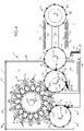
- the installation 1 is equipped with an ejector 29 positioned in line with the ejection point PE , movable between an inactive position in which the ejector 29 is moved away from the path of the preforms 3 , and an active position (shown on the FIG.4 ) in which the ejector 29 is interposed on the path of the preforms 3, at the ejection point PE , to deviate them from their trajectory and thus prevent them from being loaded onto the forming unit 4 .
- a fourth step (A.4) of the first phase (A) consists, for the control unit 11 (programmed for this purpose) and as long as the upstream auxiliary motorization M3 is not detected when stopped, to control the ejection of the blanks 3 reaching the ejection point PE .
- control unit 11 controls the passage of the ejector 29 from its inactive position to its active position.
- the second phase (B) consists, for the processing unit 11 , in ordering the maintenance of the synchronization of the secondary motorization M2 on the upstream auxiliary motorization M3 , and in maintaining the ejector 29 in the deployed position.
- the processing unit 12 is emptied of its blanks 3, since they are ejected at the ejection point PE , even though the power supply to the processing unit 12 is stopped.
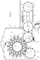
- a first step (C.1) consists, for the control unit 11 (programmed for this purpose), as soon as the processing unit 12 is detected empty of blanks 3, in ordering the desynchronization of the secondary motorization M2 of the auxiliary M3 engine ( FIG.5 ).
- a second step (C.2) consists, for the control unit 11 (programmed for this purpose), as soon as the upstream transfer auxiliary device 22 is detected empty of blanks 3, in controlling the stopping of the motorization Auxiliary M3 ( FIG.6 ).
- the control unit 11 is programmed to keep the secondary motorization M2 moving in a desynchronized manner from the auxiliary motorization M3 .
- the radiating walls 13 can be maintained under voltage, although it is preferable to reduce the power to minimize energy consumption. Keeping the walls 13 under tension makes it possible to avoid their preheating on restarting.
- the installation 1 comprises an auxiliary device 30 for the downstream transfer of the containers 2 formed from the forming unit 4 to one (or more) other machine(s). s), arranged to perform additional operations on the containers 2 (typically filling, capping, labeling).
- This downstream transfer auxiliary device 30 comprises a downstream auxiliary conveyor 31 which defines a downstream transfer path T4 .
- the downstream transfer path T4 is tangent to the forming path T1 at an unloading point PD .
- the downstream auxiliary transfer device 30 is in the form of a wheel, rotatably mounted around a downstream auxiliary axis X4 , materialized by a downstream auxiliary shaft 32 .
- the auxiliary downstream transfer device 30 further comprises a plurality of members 33 for gripping the containers 2, carried by the downstream auxiliary conveyor 31 .
- the gripping members 33 are in the form of pliers distributed around the periphery of the wheel, each provided with a pair of jaws capable of being snapped onto the neck of a container 2.
- the downstream auxiliary transfer device 30 comprises a downstream auxiliary motorization M4 , coupled to the downstream auxiliary conveyor 31 (here to the wheel).
- This downstream auxiliary motorization M4 is independent of the main motorization M1 and is controlled by the control unit 11 .
- the control unit 11 is connected to the downstream auxiliary motorization M4 by a connection which can be wired or radio frequency.
- the downstream auxiliary motorization M4 is advantageously of the torque motor type and comprises a rotor 34 integral with the downstream auxiliary shaft 32 , and a stator 35 connected to the control unit 11 which controls the intensity of the supply current.
- downstream auxiliary conveyor 31 In normal operation of the installation 1, that is to say as long as no fault is detected in the installation 1, the downstream auxiliary conveyor 31 is moved by its downstream auxiliary motorization M4 , which is synchronized on the main engine M1 to allow, at the unloading point PD , the removal by the downstream auxiliary conveyor 31 , in each open mold 7 , of the containers 2 formed in the forming unit 4 .
- the rotational speed of the downstream auxiliary M4 motorization is set to the rotational speed of the main M1 motorization (i.e. the rotational speed of the downstream auxiliary M4 motorization is maintained at a constant fraction of the rotational speed of the main M1 motorization).
- the control unit 11 maintains in all circumstances this synchronization of the downstream auxiliary motorization M4 with the main motorization M1 .
- the emergency stop of the forming unit 4 is intended to allow a maintenance operation to be carried out thereon. Access to the area in which this operation is to be carried out must be authorized for this purpose.
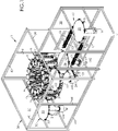
- the installation 1 comprises a cowling 36 defining a main enclosure 37 in which is housed the forming unit 4 (and, possibly, the transfer device(s) 22, 30 ).
- the cowling 36 also defines a secondary enclosure 38 , separated from the main enclosure 37 , and in which the processing unit 12 is at least partially housed.
- cowling 36 defines two separate enclosures 37, 38 which allow separate access, on the one hand, to the forming unit 4 and, on the other hand, to the processing unit 12 , it is not necessary that the processing unit 12 is stopped to allow access to the enclosure 37 main.
- control unit 11 can be programmed to, as soon as the main motorization M1 is detected when stopped, command the unlocking of the main opening 41 , as illustrated on the FIG.5 , where we see that the main opening 41 is open, even though the processing unit 12 continues to rotate.
- control unit 11 can, in addition, be programmed to, when the upstream auxiliary motorization M3 is detected when stopped, command unlocking the sash 44 secondary, as shown in the FIG.7 , where we see that the main opening 41 (or several main openings 41 ) is (are) open.
- the installation comprises an ejector 46 positioned on the downstream transfer path T4 , so as to minimize the risk that containers 2 continue their journey in the installation 1.
- the ejector 46 is connected to the control unit 11 , which controls its operation.
- a step (A.5) is provided which consists, for the control unit 11 , in ordering the movement of the ejector 46 towards a deployed position (illustrated on the FIG.4 ) in which it obstructs the passage of the containers 2 on the downstream transfer path T4 , so as to deflect them therefrom.
- the motorizations M1, M2, M3 cannot be synchronized immediately: they should be put into rotation gradually, then to converge (on command from the control unit 11 ) each speed towards the nominal speed corresponding to operation at full speed.
Landscapes
- Engineering & Computer Science (AREA)
- Manufacturing & Machinery (AREA)
- Mechanical Engineering (AREA)
- Physics & Mathematics (AREA)
- Thermal Sciences (AREA)
- Blow-Moulding Or Thermoforming Of Plastics Or The Like (AREA)
- Control Of Conveyors (AREA)
Description
L'invention a trait à la production des récipients à partir d'ébauches en matière plastique (notamment en PET). Elle concerne, plus particulièrement, une installation de production de récipients et un procédé de pilotage d'une telle installation.The invention relates to the production of containers from blanks made of plastic material (in particular PET). It relates, more particularly, to an installation for producing receptacles and a method for controlling such an installation.
Une installation de production de récipients comprend, classiquement, une unité de formage des récipients, une unité de traitement préalable (par ex. thermique) des ébauches, et un dispositif auxiliaire de transfert des ébauches de l'unité de traitement à l'unité de formage.A receptacle production installation conventionally comprises a receptacle forming unit, a unit for pre-treatment (e.g. heat) of the blanks, and an auxiliary device for transferring the blanks from the processing unit to the processing unit. forming.
L'unité de formage comprend, de manière connue, un convoyeur principal (par ex. un carrousel), qui définit un trajet de formage (typiquement circulaire), une pluralité de postes de formage portés par le convoyeur principal et incluant chacun un moule (par ex. s'ouvrant en portefeuille) à l'empreinte d'un récipient, et une motorisation principale couplée au convoyeur principal et pilotée par une unité de contrôle pour déplacer les postes de formage le long du trajet de formage.The forming unit comprises, in known manner, a main conveyor (e.g. a carousel), which defines a forming path (typically circular), a plurality of forming stations carried by the main conveyor and each including a mold ( opening in portfolio) to the footprint of a container, and a main motorization coupled to the main conveyor and driven by a control unit to move the forming stations along the forming path.
L'unité de traitement des ébauches comprend, de manière connue, un convoyeur secondaire (incluant typiquement une chaîne circulant sur des roues) définissant un trajet de traitement (formé par ex. de portions rectilignes et de portions courbes), une pluralité d'organes de préhension des ébauches, portés par le convoyeur secondaire, et au moins une paroi rayonnante devant laquelle défilent les ébauches.The blank processing unit comprises, in a known manner, a secondary conveyor (typically including a chain circulating on wheels) defining a processing path (formed for example of rectilinear portions and curved portions), a plurality of for gripping the blanks, carried by the secondary conveyor, and at least one radiating wall in front of which the blanks pass.
Le dispositif auxiliaire de transfert des ébauches de l'unité de traitement à l'unité de formage comprend, de manière connue, un convoyeur auxiliaire (par ex. une roue) définissant un trajet de transfert (typiquement circulaire) tangent au trajet de traitement et au trajet de formage, et une pluralité d'organes de préhension des ébauches portés par le convoyeur auxiliaire.The auxiliary device for transferring the blanks from the processing unit to the forming unit comprises, in known manner, an auxiliary conveyor (for example a wheel) defining a transfer path (typically circular) tangent to the processing path and to the forming path, and a plurality of grippers of the blanks carried by the auxiliary conveyor.
Une installation de ce type est très schématiquement décrite dans le brevet européen
Le déplacement des ébauches le long du trajet de traitement, du trajet de transfert et du trajet de formage doit se faire à la même cadence. Il est donc nécessaire de coupler le convoyeur secondaire et le convoyeur auxiliaire au convoyeur principal. Ce couplage est classiquement effectué de manière physique, au moyen de courroies, qui circulent sur des poulies équipant respectivement le convoyeur principal, le convoyeur secondaire et le convoyeur auxiliaire.The movement of the blanks along the processing path, the transfer path and the forming path must be at the same rate. It is therefore necessary to couple the secondary conveyor and the auxiliary conveyor to the main conveyor. This coupling is conventionally carried out in a physical way, by means of belts, which circulate on pulleys respectively equipping the main conveyor, the secondary conveyor and the auxiliary conveyor.
Il arrive cependant que l'unité de formage soit affectée d'un défaut nécessitant son arrêt d'urgence pour permettre une opération humaine de maintenance. Un défaut typique est un grippage du mécanisme d'ouverture et de fermeture d'un moule, ou encore lorsqu'une pièce, déformée par l'usure ou la fatigue, se déforme, se fissure, ou se casse.It does happen, however, that the forming unit is affected by a defect requiring it to be stopped in an emergency to allow a human maintenance operation. A typical defect is a seizure of the opening and closing mechanism of a mold, or when a part, deformed by wear or fatigue, deforms, cracks, or breaks.
Compte tenu du couplage physique du convoyeur secondaire au convoyeur principal, l'arrêt d'urgence de l'unité de formage induit l'arrêt simultané de l'unité de traitement.Given the physical coupling of the secondary conveyor to the main conveyor, the emergency stop of the forming unit induces the simultaneous stop of the processing unit.
Il en résulte que les ébauches présentes dans l'unité de traitement sont arrêtées, et sont surexposées au traitement, c'est-à-dire exposées à celui-ci pendant une durée supérieure à la durée nominale correspondant à la cadence de production. Lorsque le traitement est un conditionnement thermique (c'est-à-dire une chauffe, généralement conduite au moyen de lampes halogènes), la surexposition peut provoquer la fonte des ébauches, voire même leur brûlure. Lorsque le traitement est une décontamination aux ultraviolets (généralement conduite au moyen de lampes à décharge et vapeur de mercure), la surexposition est susceptible de modifier les propriétés de la matière.As a result, the blanks present in the processing unit are stopped, and are overexposed to the processing, that is to say exposed to the latter for a duration greater than the nominal duration corresponding to the production rate. When the treatment is a thermal conditioning (that is to say a heating, generally carried out by means of halogen lamps), the overexposure can cause the melting of the blanks, or even their burning. When the treatment is ultraviolet decontamination (generally carried out using discharge lamps and mercury vapor), the overexposure is likely to modify the properties of the material.
Pour éviter une telle surexposition, la désactivation des parois rayonnantes est généralement commandée en même temps que l'arrêt de l'unité de formage. Certes, on évite la surexposition, mais les ébauches présentes dans l'unité de traitement sont perdues et celle-ci doit en être vidangée avant que la production ne puisse reprendre ; en outre, les parois rayonnantes doivent être progressivement réactivées. Cette réactivation prend du temps, notamment dans le cas de lampes halogènes qui nécessitent une longue préchauffe en raison de leur importante inertie thermique.To avoid such overexposure, the deactivation of the radiating walls is generally ordered at the same time as the stopping of the forming unit. Admittedly, overexposure is avoided, but the blanks present in the processing unit are lost and the latter must be emptied of them before production can resume; in addition, the radiant walls must be gradually reactivated. This reactivation takes time, especially in the case of halogen lamps which require long preheating due to their high thermal inertia.
Le document
Il résulte d'une telle procédure d'arrêt d'urgence une perte de productivité. Rappelons que les installations modernes de production de récipients tournent à des cadences de l'ordre de 40 000 récipients par heure : ainsi, à chaque minute perdue, ce sont près de 700 récipients qui sont perdus.Such an emergency stop procedure results in a loss of productivity. It should be remembered that modern container production facilities run at rates of the order of 40,000 containers per hour: thus, for every minute lost, nearly 700 containers are lost.
Un premier objectif de l'invention est de limiter, à l'occasion d'une procédure d'arrêt d'urgence d'une l'installation de production de récipients, la perte de récipients.A first objective of the invention is to limit, on the occasion of an emergency shutdown procedure of a container production installation, the loss of containers.
Un deuxième objectif est d'accélérer la reprise de la production une fois la maintenance effectuée et rétabli le bon fonctionnement de l'installation.A second objective is to speed up the resumption of production once the maintenance has been carried out and the proper functioning of the installation has been restored.
A cet effet, il est proposé, en premier lieu, une installation de production de récipients à partir d'ébauches en matière plastique, qui comprend :
- Une unité de formage des récipients à partir des ébauches, qui comprend :
- Un convoyeur principal définissant un trajet de formage ;
- Une pluralité de postes de formage portés par le convoyeur principal et incluant chacun un moule à l'empreinte d'un récipient ;
- Une motorisation principale couplée au convoyeur principal pour déplacer les postes de formage le long du trajet de formage ;
- Une unité de traitement préalable des ébauches, qui comprend :
- Un convoyeur secondaire définissant un trajet de traitement ;
- Une pluralité d'organes de préhension des ébauches, portés par le convoyeur secondaire ;
- Une motorisation secondaire couplée au convoyeur secondaire, indépendante de la motorisation principale et pilotée par l'unité de contrôle ;
- Un dispositif auxiliaire de transfert des ébauches de l'unité de traitement à l'unité de formage, qui comprend :
- Un convoyeur auxiliaire définissant un trajet de transfert tangent au trajet de traitement en un point de transfert, et au trajet de formage en un point de chargement ;
- Une pluralité d'organes de préhension des ébauches, portés par le convoyeur auxiliaire ;
- Une motorisation auxiliaire couplée au convoyeur auxiliaire, indépendante de la motorisation principale et pilotée par l'unité de contrôle ;
- Une unité de contrôle pilotant la motorisation principale ;
- Une unité de contrôle pilotant la motorisation principale, la motorisation secondaire et la motorisation auxiliaire, et programmée pour :
- ∘ Tant qu'aucun défaut n'est détecté au moins dans l'unité de formage, synchroniser la motorisation auxiliaire sur la motorisation principale, et la motorisation secondaire sur la motorisation auxiliaire ;
- ∘ Dès lors qu'un défaut est détecté dans l'unité de formage, interrompre l'alimentation en ébauches de l'unité de traitement, commander la désynchronisation de la motorisation auxiliaire de la motorisation principale, commander l'arrêt de la motorisation principale, et, le cas échéant, commander l'éjection des ébauches parvenant à un point d'éjection situé en amont du point de chargement.
- A unit for forming containers from blanks, which includes:
- A main conveyor defining a forming path;
- A plurality of forming stations carried by the main conveyor and each including a mold with the imprint of a container;
- A main motorization coupled to the main conveyor to move the forming stations along the forming path;
- A pre-processing unit for blanks, which includes:
- A secondary conveyor defining a processing path;
- A plurality of members for gripping the blanks, carried by the secondary conveyor;
- A secondary motorization coupled to the secondary conveyor, independent of the main motorization and controlled by the control unit;
- An auxiliary device for transferring blanks from the processing unit to the forming unit, which comprises:
- An auxiliary conveyor defining a transfer path tangent to the processing path at a transfer point, and to the forming path at a loading point;
- A plurality of members for gripping the blanks, carried by the auxiliary conveyor;
- An auxiliary motorization coupled to the auxiliary conveyor, independent of the main motorization and controlled by the control unit;
- A control unit controlling the main motorization;
- A control unit controlling the main motorization, the secondary motorization and the auxiliary motorization, and programmed for:
- ∘ As long as no fault is detected at least in the forming unit, synchronize the auxiliary motorization on the main motorization, and the secondary motorization on the auxiliary motorization;
- ∘ As soon as a fault is detected in the forming unit, interrupt the supply of blanks to the processing unit, order the desynchronization of the auxiliary motorization of the main motorization, command the stopping of the main motorization, and, where appropriate, controlling the ejection of blanks arriving at an ejection point located upstream of the loading point.
De la sorte, l'arrêt de l'unité de formage peut être commandé tout en maintenant l'unité de traitement en mouvement. L'intervention sur l'unité de formage peut être anticipée, ce qui limite les pertes et permet d'accroître la productivité. En outre, la reprise de la production peut être accélérée.In this way, the stopping of the forming unit can be controlled while keeping the processing unit in motion. Intervention on the forming unit can be anticipated, which limits losses and increases productivity. In addition, the resumption of production can be accelerated.
Diverses caractéristiques supplémentaires peuvent être prévues, seules ou en combinaison.Various additional features may be provided, alone or in combination.
Ainsi, par exemple, l'unité de contrôle est programmée pour, dès lors que l'unité de traitement est détectée vide d'ébauches, commander la désynchronisation de la motorisation secondaire de la motorisation auxiliaire.Thus, for example, the control unit is programmed to, as soon as the processing unit is detected empty of blanks, control the desynchronization of the secondary motorization of the auxiliary motorization.
L'unité de traitement peut en outre être programmée pour, dès lors que le dispositif auxiliaire de transfert est détecté vide d'ébauches, commander l'arrêt de la motorisation auxiliaire.The processing unit can also be programmed to, when the auxiliary transfer device is detected empty of blanks, control the stopping of the auxiliary motorization.
Dans ce cas, l'unité de traitement est avantageusement programmée pour maintenir en mouvement la motorisation secondaire de manière désynchronisée de la motorisation auxiliaire.In this case, the processing unit is advantageously programmed to keep the secondary motorization moving in a desynchronized manner from the auxiliary motorization.
Chaque motorisation est un par ex. un moteur-couple.Each motorization is one e.g. a torque motor.
Selon un mode de réalisation, l'installation comprend par ailleurs un capotage définissant une enceinte principale dans laquelle est logée l'unité de formage, et une enceinte secondaire séparée de l'enceinte principale et dans laquelle est au moins partiellement logée l'unité de traitement, ce capotage comprenant :
- Un châssis définissant au moins un dormant principal qui borde l'enceinte principale, et un dormant secondaire qui borde l'enceinte secondaire ;
- Au moins un ouvrant principal monté sur le dormant principal entre une position ouverte dans laquelle l'ouvrant principal est écarté du dormant principal pour donner accès à l'enceinte principale par l'extérieur, et une position fermée dans laquelle l'ouvrant principal est logé dans le dormant principal pour interdire l'accès à l'enceinte principale par l'extérieur ;
- Un système de verrouillage et déverrouillage de l'ouvrant principal en position fermée, relié à l'unité de contrôle ;
- A frame defining at least one main frame which borders the main enclosure, and a secondary frame which borders the secondary enclosure;
- At least one main sash mounted on the main frame between an open position in which the main sash is separated from the main frame to provide access to the main enclosure from the outside, and a closed position in which the main sash is housed in the main frame to prevent access to the main enclosure from the outside;
- A system for locking and unlocking the main sash in the closed position, connected to the control unit;
Dans ce cas, l'unité de contrôle est avantageusement programmée pour, dès lors que la motorisation principale est détectée à l'arrêt, commander le déverrouillage de l'ouvrant secondaire.In this case, the control unit is advantageously programmed to, as soon as the main motorization is detected when stopped, command the unlocking of the secondary opening.
Il est proposé, en deuxième lieu, un procédé de pilotage d'une installation de production de récipients telle que présentée ci-dessus, qui comprend les opérations, commandées par l'unité de contrôle, consistant à :
- ∘ Tant qu'aucun défaut n'est détecté au moins dans l'unité de formage, synchroniser la motorisation auxiliaire sur la motorisation principale, et la motorisation secondaire sur la motorisation auxiliaire ;
- ∘ Dès lors qu'un défaut est détecté dans l'unité de formage, interrompre l'alimentation en ébauches de l'unité de traitement, commander la désynchronisation de la motorisation auxiliaire de la motorisation principale, commander l'arrêt de la motorisation principale, et, le cas échéant, commander l'éjection des ébauches parvenant à un point d'éjection situé en amont du point de chargement.
- ∘ As long as no fault is detected at least in the forming unit, synchronize the auxiliary motorization on the main motorization, and the secondary motorization on the auxiliary motorization;
- ∘ As soon as a defect is detected in the forming unit, interrupt the supply of blanks to the processing unit, control the desynchronization of the auxiliary motorization of the main motorization, control the stopping of the main motorization, and, if necessary, control the ejection of the blanks arriving at an ejection point located upstream of the loading point.
Les opérations supplémentaires suivantes peuvent être prévues, commandées par l'unité de contrôle :
- ∘ Redémarrer la motorisation principale ;
- ∘ Redémarrer la motorisation auxiliaire si elle est détectée à l'arrêt ;
- ∘ Resynchroniser la motorisation auxiliaire sur la motorisation principale ;
- ∘ Débloquer l'alimentation en ébauches de l'unité de traitement.
- ∘ Restart the main engine;
- ∘ Restart the auxiliary motorization if it is detected when stopped;
- ∘ Resynchronize the auxiliary motorization on the main motorization;
- ∘ Unblock the supply of blanks to the treatment unit.
D'autres objets et avantages de l'invention apparaîtront à la lumière de la description d'un mode de réalisation, faite ci-après en référence aux dessins annexés dans lesquels :
- La
FIG.1 est une vue en perspective, de dessus, d'une installation de production de récipients ; - La
FIG.2 est une vue en perspective, de dessous, de l'installation de laFIG.1 ; - La
FIG.3 est une vue de dessus de l'installation ; - Les
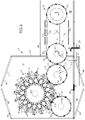
FIG.4 ,FIG.5 ,FIG.6 sont des vues similaires à laFIG.3 , illustrant différentes phases successives d'un arrêt d'urgence, et laFIG.7 une phase de reprise de la production ; les déplacements des différents convoyeurs y sont illustrés par des flèches en trait gras noir, l'absence de flèche signifiant l'arrêt du convoyeur ;
- The
FIG.1 is a perspective view, from above, of a container production facility; - The
FIG.2 is a perspective view, from below, of the installation of theFIG.1 ; - The
FIG.3 is a top view of the installation; - The
FIG.4 ,FIG.5 ,FIG.6 are views similar to theFIG.3 , illustrating the different successive phases of an emergency stop, and theFIG.7 a production resumption phase; the movements of the various conveyors are illustrated therein by arrows in bold black lines, the absence of an arrow signifying the stoppage of the conveyor;
Sur les dessins est représentée une installation 1 de production de récipients 2 à partir d'ébauches 3 en matière plastique. Selon un mode de réalisation illustré sur les dessins, les ébauches 3 sont des préformes, directement issue d'un moulage par injection. Cependant, dans d'autres modes de réalisation, les ébauches 3 pourraient être des récipients intermédiaires, ayant subi une ou plusieurs opérations préparatoires (comme un présoufflage). La matière est par ex. un polytéréphtalate d'éthylène (PET).In the drawings is shown an
L'installation 1 comprend, en premier lieu, une unité 4 de formage des récipients 2 (par soufflage ou étirage soufflage) à partir des ébauches 3. Cette unité 4 de formage comprend un convoyeur 5 principal qui définit un trajet T1 de formage. Dans l'exemple illustré sur les dessins, le convoyeur 5 principal est un carrousel tournant, qui comprend une roue montée en rotation autour d'un axe X1 principal. Dans cet exemple, le trajet T1 de formage est circulaire.The
L'unité 4 de formage comprend une pluralité de postes 6 de formage portés par le convoyeur 5 principal et incluant chacun un moule 7 à l'empreinte d'un récipient 3. The forming
Dans l'exemple illustré, chaque moule 7 est monté sur le convoyeur 5 principal ; chaque moule 7 peut adopter :
- Une position ouverte pour permettre l'introduction d'une ébauche 3 et l'évacuation d'un récipient 2 formé, et
- Une position fermée pour permettre le formage d'un récipient 2 à partir d'une ébauche 3.
- An open position to allow the introduction of a blank 3 and the evacuation of a
container 2 formed, and - A closed position to allow the forming of a
container 2 from a blank 3.
Selon un mode de réalisation illustré sur les dessins, chaque moule 7 comprend deux demi-moules articulés autour d'une charnière commune pour être soit écartés l'un de l'autre (dans la position ouverte du moule 7), soit réunis (dans la position fermée du moule 7). Chaque moule 7 est équipé d'un mécanisme d'ouverture et de fermeture (par ex. à bielles et came).According to an embodiment illustrated in the drawings, each
Chaque poste 6 de formage comprend en outre un dispositif d'injection, dans chaque ébauche 3 logée dans le moule 7, d'un fluide sous pression (par ex. de l'air) pour déformer l'ébauche 3 jusqu'à lui conférer l'empreinte du modèle de récipient lorsque la matière se trouve plaquée intérieurement contre le moule 7. Each forming
Selon un mode particulier de réalisation, l'unité 4 de formage est une machine d'étirage soufflage, et chaque poste 6 de formage est équipé d'une tige d'étirage montée en translation par rapport au moule 7 pour étirer l'ébauche 3 en même temps qu'elle est soufflée par injection de fluide.According to a particular embodiment, the forming
L'unité 4 de formage comprend une motorisation M1 principale couplée au convoyeur 5 principal pour déplacer les postes 6 de formage le long du trajet T1 de formage. Plus précisément, dans l'exemple illustré, les postes 6 de formage sont entraînés dans un mouvement cyclique rotatif.The forming
Dans le mode de réalisation illustré sur la
Plus précisément, et selon un mode préféré de réalisation, la motorisation M1 principale est du type moteur-couple, c'est-à-dire qu'il s'agit d'un servomoteur sans balais à aimants permanents (encore appelé moteur synchrone à aimants permanents, ou encore moteur sans balais à courant continu). Divers modèles sont notamment proposés par la société Etel. Cette motorisation M1 comprend ainsi un rotor 9 central, directement monté sur l'arbre 8 principal (et solidaire en rotation de celui-ci) et un stator 10 périphérique.More precisely, and according to a preferred embodiment, the main motorization M1 is of the torque motor type, that is to say it is a brushless servomotor with permanent magnets (also called synchronous motor with permanent magnets, or brushless DC motor). Various models are notably offered by the company Etel. This motorization M1 thus comprises a central rotor 9 , directly mounted on the main shaft 8 (and integral in rotation with the latter) and a
Selon un exemple de réalisation, la motorisation M1 principale comprend une ou plusieurs bobines solidaire(s) du stator 10, et une série d'aimants permanents solidaires du rotor 9. Lorsque la bobine est parcourue par un courant électrique, elle induit dans les aimants permanents une force électromotrice qui anime le rotor 9 d'un mouvement de rotation dont la vitesse est proportionnelle à l'intensité du courant.According to an exemplary embodiment, the main motorization M1 comprises one or more coils integral with the
L'installation 1 comprend, en deuxième lieu, une unité 11 (électronique ou informatique) de contrôle pilotant la motorisation M1 principale.The
L'unité 11 de contrôle est programmable; elle est reliée à la motorisation 8 principale par une liaison qui peut être filaire ou à radiofréquence.The
L'unité 11 de contrôle se présente par ex. sous forme d'un automate programmable industriel (API), pourvu d'une électronique de commande (par ex. un processeur) et une interface homme-machine (typiquement un écran associé à un clavier, ou éventuellement un écran tactile) par laquelle un opérateur peut introduire des instructions ou prendre connaissance d'informations relatives au fonctionnement de l'installation 1. The
Dans le mode de réalisation illustrée, l'unité 11 de contrôle est reliée au stator 10 pour commander l'intensité du courant délivré à la bobine.In the illustrated embodiment, the
L'installation 1 comprend, en troisième lieu, une unité 12 de traitement préalable des ébauches 3. The
L'unité 12 de traitement est équipée de parois 13 rayonnantes devant lesquelles les ébauches 3 sont déplacées pour être exposées au rayonnement.The
Selon un mode de réalisation, l'unité 12 de traitement est une unité de conditionnement thermique (c'est-à-dire de chauffe) des ébauches 3, agencée pour les porter à une température supérieure à la température de transition vitreuse de la matière (laquelle est de 80°C environ pour le PET). Dans ce cas, les parois 13 rayonnantes sont munies de sources de rayonnement infrarouge, typiquement des lampes halogènes.According to one embodiment, the
Selon un autre mode de réalisation, l'unité 12 de traitement est une unité de décontamination par rayonnement ultraviolet. Dans ce cas, les parois 13 rayonnantes sont munies de sources de rayonnement ultraviolet, typiquement des lampes à décharge et vapeur de mercure.According to another embodiment, the
L'unité 1 de traitement comprend un convoyeur 14 secondaire qui définit un trajet T2 de traitement parcouru (au moins partiellement) par les ébauches 3, ainsi qu'une pluralité d'organes 15 de préhension des ébauches 3, portés par le convoyeur 14 secondaire.The
Le convoyeur 14 secondaire comprend par ex. une chaîne, et les organes 15 de préhension peuvent se présenter sous forme de dispositifs appelés tournettes, équipés d'un mandrin qui vient s'emmancher dans le col de chaque ébauche 3 pour, lors du parcours du trajet T2 de traitement, entraîner en rotation l'ébauche 3 pendant son exposition au rayonnement des parois 13. The
Dans l'exemple illustré sur les dessins, une telle chaîne n'est, par souci de clarté, pas représentée. Le trajet T2 de traitement illustré comprend deux portions droites - chacune bordée de parois 13 rayonnantes en regard l'une de l'autre - reliées entre elles par deux portions courbes. Dans cet exemple, les portions courbes du trajet T2 de traitement sont définies par des roues pourvues de pinces de préhension des ébauches 3, ce qui ne correspond pas nécessairement à la réalité matérielle de l'unité 12 de traitement mais a le mérite de schématiser de grossière son architecture.In the example illustrated in the drawings, such a chain is, for the sake of clarity, not shown. The illustrated treatment path T2 comprises two straight portions—each lined with radiating
Ainsi, dans l'exemple illustré, le convoyeur 14 secondaire comprend une roue 16 motrice montée en rotation sur un axe X2 secondaire, matérialisé par un arbre 17 secondaire. Les organes 15 de préhension illustrés ici sont des pinces réparties à la périphérie de la roue 16 motrice, chacune pourvue d'une paire de mors aptes à venir s'encliqueter sur le col d'une ébauche 3. Thus, in the example illustrated, the
Par ailleurs, l'unité 12 de traitement comprend une motorisation M2 secondaire, couplée au convoyeur 14 secondaire (ici à la roue secondaire). Cette motorisation M2 secondaire est indépendante de la motorisation M1 principale et est pilotée par l'unité 11 de contrôle. A cet effet, l'unité 11 de contrôle est reliée à la motorisation secondaire par une liaison qui peut être filaire ou à radiofréquence.Furthermore, the
La motorisation M2 secondaire est avantageusement du type moteur-couple et comprend un rotor 18 solidaire de l'arbre 17 secondaire et un stator 19 relié à l'unité 11 de contrôle qui en commande l'intensité du courant d'alimentation.The secondary motorization M2 is advantageously of the torque-motor type and comprises a rotor 18 secured to the
Dans l'exemple illustré, le convoyeur 14 secondaire comprend une roue 20 suiveuse couplée à la roue 16 motrice, par ex. au moyen d'une courroie C. In the example illustrated, the
Comme illustré sur les dessins, l'installation 1 comprend un dispositif 21 d'alimentation de l'unité 12 de traitement en ébauches 3. Ce dispositif 21 d'alimentation comprend par ex. un rail incliné auquel sont suspendues les ébauches 3, et le long duquel elles coulissent avant d'entrer dans l'unité 12 de traitement.As illustrated in the drawings, the
L'installation 1 comprend, en quatrième lieu, un dispositif 22 auxiliaire de transfert amont des ébauches 3 de l'unité 12 de traitement à l'unité 4 de formage.The
Ce dispositif 22 auxiliaire de transfert amont comprend un convoyeur 23 auxiliaire amont qui définit un trajet T3 de transfert amont. Le trajet T3 de transfert amont est tangent au trajet T2 de traitement en un point PT de transfert. Le trajet T3 de transfert est par ailleurs tangent au trajet T1 de formage en un point PC de chargement.This upstream transfer
Selon un mode de réalisation illustré sur les dessins, le convoyeur 23 auxiliaire amont se présente sous forme d'une roue, montée en rotation autour d'un axe X3 auxiliaire, matérialisé par un arbre 24 auxiliaire amont.According to an embodiment illustrated in the drawings, the upstream
Le dispositif 22 auxiliaire de transfert amont comprend en outre une pluralité d'organes 25 de préhension des ébauches, portés par le convoyeur 23 auxiliaire amont. Dans l'exemple illustré, les organes 25 de préhension se présentent sous forme de pinces réparties à la périphérie de la roue, chacune pourvue d'une paire de mors aptes à venir s'encliqueter sur le col d'une ébauche 3. The upstream
Comme illustré notamment sur la
La motorisation M3 auxiliaire amont est avantageusement du type moteur-couple et comprend un rotor 26 solidaire de l'arbre 24 auxiliaire amont, et un stator 27 relié à l'unité 11 de contrôle qui en commande l'intensité du courant d'alimentation.The upstream auxiliary motorization M3 is advantageously of the torque-motor type and comprises a
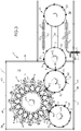
En fonctionnement normal de l'installation 1, c'est-à-dire tant qu'aucun défaut n'est détecté dans l'installation 1 (et au moins dans l'unité 12 de traitement), le convoyeur 5 principal, le convoyeur 14 secondaire et le convoyeur 23 auxiliaire amont sont mus par leurs motorisations M1, M2, M3 respectives, lesquelles, pilotées toutes séparément par l'unité 11 de contrôle, sont néanmoins synchronisées pour permettre :
- Au point PT de transfert, le prélèvement, par le convoyeur 23 auxiliaire amont, des ébauches 3 issues du convoyeur 14 secondaire ;
- Au point PC de déchargement, la dépose, par le convoyeur 23 auxiliaire de transfert amont, des ébauches 3 dans les moules 7.
- At the transfer point PT , the removal, by the upstream
auxiliary conveyor 23 , of theblanks 3 from thesecondary conveyor 14 ; - At the point PC of unloading, the deposit, by the upstream
auxiliary transfer conveyor 23 , of theblanks 3 in themolds 7.
Plus précisément, l'unité 11 de contrôle est programmée pour, tant qu'aucun défaut n'est détecté au moins dans l'unité 12 de traitement, synchroniser :
- La motorisation M3 auxiliaire amont sur la motorisation M1 principale, et
- La motorisation M2 secondaire sur la motorisation M3 auxiliaire amont.
- The upstream auxiliary M3 motorization on the main M1 motorization, and
- The secondary M2 motorization on the upstream auxiliary M3 motorization.
En d'autres termes, la vitesse de rotation de la motorisation M3 auxiliaire amont est calée sur la vitesse de rotation de la motorisation M1 principale (c'est-à-dire que la vitesse de rotation de la motorisation M3 auxiliaire amont est maintenue à une fraction constante de la vitesse de rotation de la motorisation M1 principale).In other words, the rotational speed of the upstream auxiliary M3 motorization is set to the rotational speed of the main M1 motorization (i.e. the rotational speed of the upstream auxiliary M3 motorization is maintained at a constant fraction of the rotational speed of the main M1 motorization).
Quant à la vitesse de rotation de la motorisation M2 secondaire, elle est calée sur la vitesse de rotation de la motorisation M3 auxiliaire amont.As for the rotational speed of the secondary M2 motorization, it is set to the rotational speed of the upstream auxiliary M3 motorization.
En revanche, dès lors qu'un défaut est détecté dans l'unité 4 de formage, ces synchronisations ne sont pas maintenues.On the other hand, when a fault is detected in the forming
Une mise en défaut de l'unité 4 de formage peut être déclarée par ex. lorsqu'un moule présente un coincement à l'ouverture ou à la fermeture. Un tel défaut peut être détecté au moyen de capteurs de positions ou de proximités montés sur les moules 7. A fault in the forming
Quelle que soit l'origine du défaut, dans la mesure où il nécessite un arrêt de l'unité 4 de formage, l'unité 11 de contrôle est programmée pour, dès lors que ce défaut est détecté, exécuter une procédure d'arrêt d'urgence de qui comprend plusieurs phases successives, à savoir :
- Une première phase (A) de mise à l'arrêt de l'unité 4 de formage (
FIG.4 ,FIG.5 ) et d'arrêt de l'alimentation en ébauches 3 de l'unité 12 traitement ; - Une deuxième phase (B) de vidange des ébauches 3 de l'unité 12 de traitement ;
- Une troisième phase (C) de mise à l'arrêt du dispositif 22 auxiliaire de transfert amont (
FIG.6 ).
- A first phase (A) of shutting down the forming unit 4 (
FIG.4 ,FIG.5 ) and stopping the supply ofblanks 3 to thetreatment unit 12 ; - A second phase (B) of emptying the
blanks 3 from theprocessing unit 12 ; - A third phase (C) of shutting down the auxiliary upstream transfer device 22 (
FIG.6 ).
Ces trois phases (A), (B), (C) peuvent se chevaucher dans le temps.These three phases (A), (B), (C) can overlap in time.
La première phase (A) comprend plusieurs étapes.The first phase (A) includes several steps.
Une première étape (A.1) consiste, pour l'unité 11 de contrôle, (programmée à cet effet), à interrompre l'alimentation en ébauches 3 de l'unité 12 de traitement.A first step (A.1) consists, for the
Cette étape est par ex. réalisée par blocage des ébauches 3 au sein (ou immédiatement en aval) du dispositif 21 d'alimentation. Ainsi, dans l'exemple illustré, l'installation 1 comprend un actionneur 28 mobile entre une position rétractée (
Dans ce cas, pour conduire l'étape (A.1), l'unité 11 de contrôle commande le passage de l'actionneur 28 de sa position rétractée à sa position déployée.In this case, to carry out step (A.1), the
Une deuxième étape (A.2) consiste pour l'unité 11 de contrôle, (programmée à cet effet), à commander la désynchronisation de la motorisation auxiliaire M3 amont de la motorisation M1 principale. La vitesse de rotation de la motorisation M3 auxiliaire (et donc la vitesse de déplacement du convoyeur 23 auxiliaire amont) n'est, dès lors, plus dépendante de la vitesse de rotation de la motorisation M1 principale.A second step (A.2) consists for the
Cela permet à l'unité 11 de contrôle de piloter le mouvement du convoyeur 23 auxiliaire amont sans interférer avec le mouvement du convoyeur 5 principal.This allows the
Une troisième étape (A.3) consiste, pour l'unité 11 de contrôle (programmée à cet effet), à commander l'arrêt de la motorisation M1 principale.A third step (A.3) consists, for the control unit 11 (programmed for this purpose), in controlling the stopping of the main motorization M1 .
L'arrêt de la motorisation M1 principale n'est pas immédiat, car le convoyeur 5 principal est affecté d'une importante inertie en raison de sa masse. Concrètement, la commande d'arrêt de la motorisation M1 principale peut s'effectuer soit par une réduction progressive de la vitesse de rotation de la motorisation M1 principale, soit par une mise en roue libre de la motorisation M1 principale, accompagnée d'un freinage de l'arbre 17 secondaire (freinage commandé par l'unité 11 de contrôle). Ce freinage peut être commandé par l'intermédiaire d'un circuit hydraulique.The stoppage of the main engine M1 is not immediate, because the
Pour limiter les pertes, il convient d'interrompre le transfert d'ébauches 3 vers l'unité 4 de formage.To limit losses, it is necessary to interrupt the transfer of
A cet effet, il convient d'éjecter les ébauches 3 avant qu'elles ne parviennent au point PC de chargement.To this end, the
Il est donc prévu, sur le trajet T3 de transfert, un point PE d'éjection situé en amont du point PC de chargement (dans le sens de déplacement ordinaire des ébauches 3 le long du trajet T3 de transfert en fonctionnement normal de l'installation 1). Ici, le terme « amont » est exclusif, c'est-à-dire que le point PE d'éjection ne saurait être confondu avec le point PC de chargement.There is therefore provided, on the transfer path T3 , an ejection point PE located upstream of the loading point PC (in the direction of ordinary movement of the
Concrètement, pour permettre l'éjection des ébauches 3, l'installation 1 est équipée d'un éjecteur 29 positionné au droit du point PE d'éjection, mobile entre une position inactive dans laquelle l'éjecteur 29 est écarté du trajet des préformes 3, et une position active (représentée sur la
Ainsi, une quatrième étape (A.4) de la première phase (A) consiste, pour l'unité 11 de contrôle (programmée à cet effet) et tant que la motorisation M3 auxiliaire amont n'est pas détectée à l'arrêt, à commander l'éjection des ébauches 3 parvenant au point PE d'éjection.Thus, a fourth step (A.4) of the first phase (A) consists, for the control unit 11 (programmed for this purpose) and as long as the upstream auxiliary motorization M3 is not detected when stopped, to control the ejection of the
Concrètement, pour conduire l'étape (A.4), l'unité 11 de contrôle commande le passage de l'éjecteur 29 de sa position inactive à sa position active.Concretely, to carry out step (A.4), the
L'éjection des ébauches 3 se poursuit tant que le convoyeur 23 auxiliaire amont n'est pas détecté vide d'ébauches 3. The ejection of
La deuxième phase (B) consiste, pour l'unité 11 de traitement, à commander le maintien de la synchronisation de la motorisation M2 secondaire sur la motorisation M3 auxiliaire amont, et à maintenir l'éjecteur 29 en position déployée.The second phase (B) consists, for the
De la sorte, l'unité 12 de traitement se vide de ses ébauches 3, puisqu'elles sont éjectées au point PE d'éjection, alors même que l'alimentation de l'unité 12 de traitement est stoppée.In this way, the
Cette vidange se poursuit jusqu'à ce que le dispositif 22 de transfert auxiliaire amont soit détecté vide d'ébauches 3. This emptying continues until the upstream
Il est souhaitable d'éviter l'arrêt complet de l'unité 12 de traitement, car son redémarrage, qui s'accompagne d'un long préchauffage des parois 13 rayonnantes, est trop lent. L'unité 12 de traitement continue par conséquent de tourner.It is desirable to avoid the complete shutdown of the
Pour autant, il n'est pas nécessaire de maintenir le mouvement du dispositif 22 de transfert auxiliaire amont, qui peut par conséquent être mis à l'arrêt. Il convient cependant de le découpler de l'unité 12 de traitement, qui demeure en mouvement.However, it is not necessary to maintain the movement of the upstream
C'est pourquoi la troisième phase (C) comprend plusieurs étapes.This is why the third phase (C) includes several steps.
Une première étape (C.1) consiste, pour l'unité 11 de contrôle (programmée à cet effet), dès lors que l'unité 12 de traitement est détectée vide d'ébauches 3, à commander la désynchronisation de la motorisation M2 secondaire de la motorisation M3 auxiliaire (
Une deuxième étape (C.2) consiste, pour l'unité 11 de contrôle (programmée à cet effet), dès lors que le dispositif 22 auxiliaire de transfert amont est détecté vide d'ébauches 3, à commander l'arrêt de la motorisation M3 auxiliaire (
Pour maintenir en mouvement l'unité 12 de traitement, l'unité 11 de contrôle est programmée pour maintenir en mouvement la motorisation M2 secondaire de manière désynchronisée de la motorisation M3 auxiliaire. Les parois 13 rayonnante peuvent être maintenues sous tension, même s'il est préférable d'en diminuer la puissance pour minimiser la consommation d'énergie. Le maintien sous tension des parois 13 permet d'éviter leur préchauffe au redémarrage.To keep the
On notera que, selon un mode particulier de réalisation illustré sur les dessins, l'installation 1 comprend un dispositif 30 auxiliaire de transfert aval des récipients 2 formés depuis l'unité 4 de formage vers une (ou plusieurs) autre(s) machine(s), agencée pour effectuer des opérations complémentaires sur les récipients 2 (typiquement remplissage, bouchage, étiquetage).It will be noted that, according to a particular embodiment illustrated in the drawings, the
Ce dispositif 30 auxiliaire de transfert aval comprend un convoyeur 31 auxiliaire aval qui définit un trajet T4 de transfert aval. Le trajet T4 de transfert aval est tangent au trajet T1 de formage en un point PD de déchargement.This downstream transfer
Selon un mode de réalisation illustré sur les dessins, le dispositif 30 auxiliaire de transfert aval se présente sous forme d'une roue, montée en rotation autour d'un axe X4 auxiliaire aval, matérialisé par un arbre 32 auxiliaire aval.According to an embodiment illustrated in the drawings, the downstream
Le dispositif 30 auxiliaire de transfert aval comprend en outre une pluralité d'organes 33 de préhension des récipients 2, portés par le convoyeur 31 auxiliaire aval. Dans l'exemple illustré, les organes 33 de préhension se présentent sous forme de pinces réparties à la périphérie de la roue, chacune pourvue d'une paire de mors aptes à venir s'encliqueter sur le col d'un récipient 2. The auxiliary
Comme illustré notamment sur la
La motorisation M4 auxiliaire aval est avantageusement du type moteur-couple et comprend un rotor 34 solidaire de l'arbre 32 auxiliaire aval, et un stator 35 relié à l'unité 11 de contrôle qui en commande l'intensité du courant d'alimentation.The downstream auxiliary motorization M4 is advantageously of the torque motor type and comprises a
En fonctionnement normal de l'installation 1, c'est-à-dire tant qu'aucun défaut n'est détecté dans l'installation 1, le convoyeur 31 auxiliaire aval est mu par sa motorisation M4 auxiliaire aval, laquelle est synchronisée sur la motorisation M1 principale pour permettre, au point PD de déchargement, le prélèvement par le convoyeur 31 auxiliaire aval, dans chaque moule 7 ouvert, des récipients 2 formés dans l'unité 4 de formage.In normal operation of the
En d'autres termes, la vitesse de rotation de la motorisation M4 auxiliaire aval est calée sur la vitesse de rotation de la motorisation M1 principale (c'est-à-dire que la vitesse de rotation de la motorisation M4 auxiliaire aval est maintenue à une fraction constante de la vitesse de rotation de la motorisation M1 principale).In other words, the rotational speed of the downstream auxiliary M4 motorization is set to the rotational speed of the main M1 motorization (i.e. the rotational speed of the downstream auxiliary M4 motorization is maintained at a constant fraction of the rotational speed of the main M1 motorization).
L'unité 11 de contrôle maintient en toute circonstance cette synchronisation de la motorisation M4 auxiliaire aval sur la motorisation M1 principale.The
L'arrêt d'urgence de l'unité 4 de formage est destiné à permettre la conduite sur celle-ci d'une opération de maintenance. L'accès à la zone dans laquelle doit être conduite cette opération doit, à cet effet, être autorisé.The emergency stop of the forming
Dans l'exemple illustré sur la
Selon un mode particulier de réalisation, le capotage 36 définit également une enceinte 38 secondaire, séparée de l'enceinte 37 principale, et dans laquelle est au moins partiellement logée l'unité 12 de traitement.According to a particular embodiment, the
Plus précisément, ce capotage 36 comprend :
- Un châssis 39 définissant au moins un dormant 40 principal qui borde
l'enceinte 37 principale du côté de l'unité 4 de formage ; - Au moins
un ouvrant 41 principal (en pratique une porte) monté sur le dormant 40 principal entre :- Une position ouverte dans laquelle l'ouvrant 41 principal est écarté du dormant 40 principal pour donner accès à l'enceinte 37 principale par l'extérieur, et
- Une position fermée dans laquelle l'ouvrant 41 principal est logé dans le dormant 40 principal pour interdire l'accès à l'enceinte 37 principale par l'extérieur ;
- Un système 42 de verrouillage et déverrouillage de l'ouvrant 41 principal en position fermée, relié à (et piloté par)
l'unité 11 de contrôle.
- A
frame 39 defining at least onemain frame 40 which borders themain enclosure 37 on the side of the formingunit 4 ; - At least one main opening 41 (in practice a door) mounted on the
main frame 40 between:- An open position in which the
main opening 41 is moved away from themain frame 40 to give access to themain enclosure 37 from the outside, and - A closed position in which the
main opening 41 is housed in themain frame 40 to prevent access to themain enclosure 37 from the outside;
- An open position in which the
- A
system 42 for locking and unlocking themain opening 41 in the closed position, connected to (and controlled by) thecontrol unit 11 .
Selon un mode de réalisation illustré notamment sur la
- Un dormant 43 auxiliaire qui borde
l'enceinte 37 principale du côté des dispositifs 22, 30 de transfert auxiliaire ; - Au moins
un ouvrant 44 auxiliaire (en pratique une porte) monté sur le dormant 43 auxiliaire entre :- Une position ouverte dans laquelle l'ouvrant 44 auxiliaire est écarté du dormant 43 auxiliaire pour donner accès à l'enceinte 37 principale par l'extérieur du côté des dispositifs 22, 30 de transfert auxiliaire, et
- Une position fermée dans laquelle l'ouvrant 44 auxiliaire est logé dans le dormant 43 auxiliaire pour interdire l'accès à l'enceinte 37 principale par l'extérieur, du côté des dispositifs 22, 30 de transfert auxiliaire ;
- Un système 45 de verrouillage et déverrouillage de l'ouvrant 44 auxiliaire en position fermée, relié à (et piloté par)
l'unité 11 de contrôle.
- An
auxiliary frame 43 which borders themain enclosure 37 on the side of theauxiliary transfer devices - At least one auxiliary opening 44 (in practice a door) mounted on the
auxiliary frame 43 between:- An open position in which the
auxiliary opening 44 is separated from theauxiliary frame 43 to provide access to themain enclosure 37 from the outside on the side of theauxiliary transfer devices - A closed position in which the
auxiliary opening 44 is housed in theauxiliary frame 43 to prevent access to themain enclosure 37 from the outside, on the side of theauxiliary transfer devices
- An open position in which the
- A
system 45 for locking and unlocking theauxiliary opening 44 in the closed position, connected to (and controlled by) thecontrol unit 11 .
Comme le capotage 36 définit deux enceintes 37, 38 distinctes qui permettent un accès séparé, d'une part, à l'unité 4 de formage et, d'autre part, à l'unité 12 de traitement, il n'est pas nécessaire que l'unité 12 de traitement soit à l'arrêt pour autoriser l'accès à l'enceinte 37 principale.As the
En revanche, il est plus sûr d'interdire l'accès à l'enceinte 37 principale du côté des dispositifs 22, 30 de transfert auxiliaire tant que ceux-ci ne sont pas arrêtés.On the other hand, it is safer to prohibit access to the
Ainsi, l'unité 11 de contrôle peut être programmée pour, dès lors que la motorisation M1 principale est détectée à l'arrêt, commander le déverrouillage de l'ouvrant 41 principal, comme illustré sur la
Comme il peut être nécessaire d'intervenir ensuite sur les dispositifs 22, 30 de transfert auxiliaire, l'unité 11 de contrôle peut, en outre, être programmée pour, dès lors que la motorisation M3 auxiliaire amont est détectée à l'arrêt, commander le déverrouillage de l'ouvrant 44 secondaire, comme illustré sur la
Il résulte de l'architecture qui vient d'être décrite que, grâce à la mise à l'arrêt de l'unité 4 de formage indépendamment de l'unité 12 de traitement, qui peut continuer de tourner, le redémarrage de l'installation 1 après la correction du défaut, est rapide. Il n'est pas nécessaire de vidanger l'unité 12 de traitement, puisque cette vidange a déjà eu lieu pendant la phase d'arrêt de l'unité 4 de formage. Comme les parois 13 rayonnantes ont été maintenues sous tension, il n'est pas nécessaire de les préchauffer. Il en résulte une productivité accrue.It follows from the architecture which has just been described that, thanks to the shutdown of the forming
On notera qu'il peut être préférable d'éjecter les récipients 2 sortant de l'unité 4 de formage pendant l'arrêt de celle-ci. Aussi, dans l'exemple illustré sur la
L'éjecteur 46 est relié à l'unité 11 de contrôle, qui en pilote le fonctionnement. Ainsi, pendant la phase (A), il est prévu une étape (A.5) qui consiste, pour l'unité 11 de contrôle, à commander le déplacement de l'éjecteur 46 vers une position déployée (illustrée sur la
Le redémarrage de la production est piloté par l'unité 11 de contrôle (
- ∘ Redémarrer la motorisation M1 principale ;
- ∘ Redémarrer la motorisation M3 auxiliaire si elle est détectée à l'arrêt ;
- ∘ Resynchroniser la motorisation M3 auxiliaire sur la motorisation M1 principale ;
- ∘ Débloquer l'alimentation en ébauches 3 de l'unité 12 de traitement.
- ∘ Restart the main M1 motorization;
- ∘ Restart the M3 auxiliary motorization if it is detected when stopped;
- ∘ Resynchronize the auxiliary M3 motorization on the main M1 motorization;
- ∘ Unblock the supply of
blanks 3 to theprocessing unit 12 .
Comme l'unité 4 de formage, l'unité 12 de traitement et le dispositif 22 auxiliaire de transfert amont ont des inerties différentes, les motorisations M1, M2, M3 ne peuvent être synchronisées immédiatement : il convient de les mettre progressivement en rotation, puis de faire converger (sur commande de l'unité 11 de contrôle) chaque vitesse vers la vitesse nominale correspondant au fonctionnement à plein régime.As the forming
Claims (12)
- Installation (1) for producing containers (2) from blanks (3) made of plastics material, which comprises:- a unit (4) for forming containers (2) from blanks (3), which comprises:• a main conveyor (5) defining a forming path (T1) ;• a plurality of forming stations (6) borne by the main conveyor (5) and each including a mould (7) with the imprint of a container (2);• a main drive means (M1) coupled to the main conveyor (5) for moving the forming stations (6) along the forming path (T1);- a unit (12) for prior treatment of the blanks (3), which comprises:• a secondary conveyor (14) defining a treatment path (T2);• a plurality of members (15) for gripping the blanks (3), borne by the secondary conveyor (14);- an auxiliary device (22) for transferring the blanks (3) from the treatment unit (12) to the forming unit (4), which comprises:• an auxiliary conveyor (23) defining a transfer path (T3) tangential to the treatment path (T2) at a transfer point (PT), and to the forming path at a loading point (PC);• a plurality of members (25) for gripping the blanks (3), borne by the auxiliary conveyor (23) ;- a control unit (11) controlling the main drive means (M1) ;- the unit (12) for treatment of the blanks comprises a secondary drive means (M2) coupled to the secondary conveyor (14), independent of the main drive means (M1) and controlled by the control unit (11);- the auxiliary transfer device (22) comprises an auxiliary drive means (M3) coupled to the auxiliary conveyor (23), independent of the main drive means (M1) and controlled by the control unit (11);- the control unit (11) is programmed to:
as long as no fault is detected at least in the forming unit (4), synchronize the auxiliary drive means (M3) with the main drive means (M1), and the secondary drive means (M2) with the auxiliary drive means (M3);- this installation (1) being characterized in that the control unit (11) is also programmed to:
as soon as a fault is detected in the forming unit (4) :(A.1) interrupt the supply of blanks (3) to the treatment unit (12);(A.2) command the desynchronization of the auxiliary drive means (M3) from the main drive means (M1);(A.3) command the stopping of the main drive means (M1). - Installation (1) according to Claim 1, characterized in that the control unit (11) is also programmed to, as soon as a fault is detected in the forming unit (4):
(A.4) command the ejection of the blanks (3) that arrive at an ejection point (PE) situated upstream of the loading point (PC). - Installation (1) according to Claim 1 or Claim 2, characterized in that the control unit (11) is programmed to, as soon as it is detected that the treatment unit (12) is empty of blanks (3), command the desynchronization of the secondary drive means (M2) from the auxiliary drive means (M3).
- Installation (1) according to Claim 3, characterized in that the treatment unit (12) is programmed to, as soon as it is detected that the auxiliary transfer device (22) is empty of blanks (3), command the stopping of the auxiliary drive means (M3).
- Installation (1) according to Claim 3 or Claim 4, characterized in that the treatment unit (12) is programmed to keep the secondary drive means (M2) moving in a manner desynchronized from the auxiliary drive means (M3) .
- Installation (1) according to one of the preceding claims, characterized in that each drive means (M1, M2, M3) is a torque motor.
- Installation (1) according to one of the preceding claims, characterized in that it comprises a cowling (36) defining a main chamber (37) in which the forming unit (4) is housed, and a secondary chamber (38) that is separate from the main chamber (37) and in which the treatment unit (12) is at least partially housed, this cowling (36) comprising:- a chassis (39) defining at least one main frame (40) that borders the main chamber (37);- at least one main leaf (41) mounted on the main frame (40) between an open position in which the main leaf (41) is spaced apart from the main frame (40) so as to provide access to the main chamber (37) from the outside, and a closed position in which the main leaf (41) is housed in the main frame (40) so as to prevent access to the main chamber (37) from the outside;- a system (42) for locking and unlocking the main leaf (41) in the closed position, connected to the control unit (11).
- Installation (1) according to Claim 7, characterized in that the control unit (11) is programmed to, as soon as it is detected that the main drive means (M1) has stopped, command the unlocking of the main leaf (41).
- Installation (1) according to one of the preceding claims, characterized in that the control unit (11) is programmed to, as soon as it is detected that the forming unit (4) is operational,o restart the main drive means (M1);o restart the auxiliary drive means (M3) if it is detected that it has stopped;o resynchronize the auxiliary drive means (M3) with the main drive means (M1);o allow the supply of blanks (3) to the treatment unit (12) .
- Method for controlling an installation (1) for producing containers according to one of the preceding claims, which comprises the operations, commanded by the control unit (11), consisting in:∘ as long as no fault is detected at least in the forming unit (4), synchronizing the auxiliary drive means (M3) with the main drive means (M1), and the secondary drive means (M2) with the auxiliary drive means (M3);∘ as soon as a fault is detected in the forming unit (4) :(A.1) interrupting the supply of blanks (3) to the treatment unit (12);(A.2) commanding the desynchronization of the auxiliary drive means (M3) from the main drive means (M1);(A.3) commanding the stopping of the main drive means (M1).
- Method according to Claim 10, which comprises, as soon as a fault is detected in the forming unit (4), the operation consisting in:
(A.4) commanding the ejection of the blanks (3) that arrive at an ejection point (PE) situated upstream of the loading point (PC). - Method according to Claim 10 or Claim 11, which comprises the operations, commanded by the control unit (11), consisting, as soon as it is detected that the forming unit (4) is operational, in:∘ restarting the main drive means (M1);∘ restarting the auxiliary drive means (M3) if it is detected that it has stopped;∘ resynchronizing the auxiliary drive means (M3) with the main drive means (M1);∘ allowing the supply of blanks (3) to the treatment unit (12).
Applications Claiming Priority (2)
| Application Number | Priority Date | Filing Date | Title |
|---|---|---|---|
| FR1854934A FR3082139B1 (en) | 2018-06-07 | 2018-06-07 | INSTALLATION FOR PRODUCING SELECTIVE EMERGENCY STOP CONTAINERS |
| PCT/FR2019/051366 WO2019234364A1 (en) | 2018-06-07 | 2019-06-06 | Installation for producing containers, with selective emergency stop |
Publications (2)
| Publication Number | Publication Date |
|---|---|
| EP3802056A1 EP3802056A1 (en) | 2021-04-14 |
| EP3802056B1 true EP3802056B1 (en) | 2022-03-30 |
Family
ID=63722515
Family Applications (1)
| Application Number | Title | Priority Date | Filing Date |
|---|---|---|---|
| EP19737853.2A Active EP3802056B1 (en) | 2018-06-07 | 2019-06-06 | Installation for producing containers, with selective emergency stop |
Country Status (3)
| Country | Link |
|---|---|
| EP (1) | EP3802056B1 (en) |
| FR (1) | FR3082139B1 (en) |
| WO (1) | WO2019234364A1 (en) |
Family Cites Families (5)
| Publication number | Priority date | Publication date | Assignee | Title |
|---|---|---|---|---|
| FR2881979B1 (en) | 2005-02-17 | 2007-04-27 | Sidel Sas | METHOD FOR CONTROLLING A CONTAINER BLOWING MACHINE FOR CORRECTING ANOMALIES IN THE DISTRIBUTION OF MATERIAL |
| DE102012102358A1 (en) * | 2012-03-20 | 2013-09-26 | Krones Ag | Method for treating plastic containers with time reduction during the synchronization of system parts |
| DE102013014618B4 (en) * | 2013-09-04 | 2015-06-11 | Khs Corpoplast Gmbh | Synchronous safety device for transfer stations for devices for handling containers |
| DE102014005321A1 (en) * | 2014-04-10 | 2015-10-15 | Khs Corpoplast Gmbh | Apparatus and method for transporting and handling containers |
| FR3050446B1 (en) * | 2016-04-25 | 2019-06-28 | Sidel Participations | HOLLOW BODY HANDLING INSTALLATION, COMPRISING A DISTRIBUTION CONVEYOR AND SATELLITE PROCESSING UNITS |
-
2018
- 2018-06-07 FR FR1854934A patent/FR3082139B1/en active Active
-
2019
- 2019-06-06 EP EP19737853.2A patent/EP3802056B1/en active Active
- 2019-06-06 WO PCT/FR2019/051366 patent/WO2019234364A1/en unknown
Also Published As
| Publication number | Publication date |
|---|---|
| FR3082139B1 (en) | 2020-07-17 |
| WO2019234364A1 (en) | 2019-12-12 |
| EP3802056A1 (en) | 2021-04-14 |
| FR3082139A1 (en) | 2019-12-13 |
Similar Documents
| Publication | Publication Date | Title |
|---|---|---|
| EP3239079B1 (en) | Facility for handling hollow bodies, comprising a distribution conveyor and satellite treatment units | |
| EP3288742B1 (en) | Method for controlling a conveyor for hollow bodies through a heating station | |
| EP3446851B1 (en) | Method for adjusting an installation for treating a series of containers and associated installation | |
| FR2941442A1 (en) | CONTAINER PRODUCTION PLANT COMPRISING A TRANSFER WHEEL WITH VARIABLE NO. | |
| WO2009010505A1 (en) | Installation for the manufacture of containers from a preform and method of controlling the blow-moulding means of such an installation | |
| FR2949709A1 (en) | MACHINE FOR MANUFACTURING CONTAINERS COMPRISING A DEVICE CONTROL MODULE OF A MOLDING UNIT FOR OPERATING A MOLD CHANGE | |
| FR2990639A1 (en) | "INSTALLATION FOR THE MANUFACTURE OF CONTAINERS COMPRISING A ROBOT AGENCY TO INTERVENE ON AT LEAST TWO UNITS" | |
| EP3431254B1 (en) | Maintenance method of a plant for forming containers, including a resynchronisation procedure | |
| EP3802056B1 (en) | Installation for producing containers, with selective emergency stop | |
| EP0842036A1 (en) | Device for moulding containers from a thermoplastic material, and container production plant using same | |
| WO2019234363A1 (en) | Installation for producing containers, with progressive emergency stop | |
| EP3272491B1 (en) | Method of control of a manufacturing installation by safeguarding an access to maintenance works | |
| EP3427917B1 (en) | Device with a chuck for conveying hollow bodies and facility for manufacturing containers | |
| FR3032698A1 (en) | "DEVICE FOR CONVEYING CONTAINERS COMPRISING A MOBILE GRIPPING MEMBER CROSSING AT THE DIRECTION OF DISPLACEMENT" | |
| EP3873719B1 (en) | Method for managing preforms immobilised in a heating station following an interruption in production | |
| WO2018046874A2 (en) | System for conveying objects made of a thermoplastic material and comprising a hollow body with a neck | |
| EP3774278B1 (en) | Method and device for managing a rotary processing unit | |
| EP3655692B1 (en) | Facility for handling articles with secure maintenance | |
| EP3393529B1 (en) | Method of sterilizing the means of stretching a container moulding device and container manufacturing plant | |
| EP3898175B1 (en) | Device for conveying preforms for an oven and method for controlling such a device | |
| EP3856482B1 (en) | Facility for manufacturing hollow bodies comprising a member for controlling the flow of hollow bodies driven by a linear electric motor | |
| EP4286137A1 (en) | Method for the thermal conditioning of preforms | |
| WO2020070416A1 (en) | Method and device for managing a module of a container production line |
Legal Events
| Date | Code | Title | Description |
|---|---|---|---|
| STAA | Information on the status of an ep patent application or granted ep patent |
Free format text: STATUS: UNKNOWN |
|
| STAA | Information on the status of an ep patent application or granted ep patent |
Free format text: STATUS: THE INTERNATIONAL PUBLICATION HAS BEEN MADE |
|
| STAA | Information on the status of an ep patent application or granted ep patent |
Free format text: STATUS: THE INTERNATIONAL PUBLICATION HAS BEEN MADE |
|
| PUAI | Public reference made under article 153(3) epc to a published international application that has entered the european phase |
Free format text: ORIGINAL CODE: 0009012 |
|
| STAA | Information on the status of an ep patent application or granted ep patent |
Free format text: STATUS: REQUEST FOR EXAMINATION WAS MADE |
|
| 17P | Request for examination filed |
Effective date: 20210106 |
|
| AK | Designated contracting states |
Kind code of ref document: A1 Designated state(s): AL AT BE BG CH CY CZ DE DK EE ES FI FR GB GR HR HU IE IS IT LI LT LU LV MC MK MT NL NO PL PT RO RS SE SI SK SM TR |
|
| AX | Request for extension of the european patent |
Extension state: BA ME |
|
| DAV | Request for validation of the european patent (deleted) | ||
| DAX | Request for extension of the european patent (deleted) | ||
| GRAP | Despatch of communication of intention to grant a patent |
Free format text: ORIGINAL CODE: EPIDOSNIGR1 |
|
| STAA | Information on the status of an ep patent application or granted ep patent |
Free format text: STATUS: GRANT OF PATENT IS INTENDED |
|
| INTG | Intention to grant announced |
Effective date: 20211213 |
|
| GRAJ | Information related to disapproval of communication of intention to grant by the applicant or resumption of examination proceedings by the epo deleted |
Free format text: ORIGINAL CODE: EPIDOSDIGR1 |
|
| STAA | Information on the status of an ep patent application or granted ep patent |
Free format text: STATUS: REQUEST FOR EXAMINATION WAS MADE |
|
| GRAP | Despatch of communication of intention to grant a patent |
Free format text: ORIGINAL CODE: EPIDOSNIGR1 |
|
| STAA | Information on the status of an ep patent application or granted ep patent |
Free format text: STATUS: GRANT OF PATENT IS INTENDED |
|
| GRAS | Grant fee paid |
Free format text: ORIGINAL CODE: EPIDOSNIGR3 |
|
| GRAA | (expected) grant |
Free format text: ORIGINAL CODE: 0009210 |
|
| STAA | Information on the status of an ep patent application or granted ep patent |
Free format text: STATUS: THE PATENT HAS BEEN GRANTED |
|
| INTC | Intention to grant announced (deleted) | ||
| INTG | Intention to grant announced |
Effective date: 20220214 |
|
| AK | Designated contracting states |
Kind code of ref document: B1 Designated state(s): AL AT BE BG CH CY CZ DE DK EE ES FI FR GB GR HR HU IE IS IT LI LT LU LV MC MK MT NL NO PL PT RO RS SE SI SK SM TR |
|
| REG | Reference to a national code |
Ref country code: GB Ref legal event code: FG4D Free format text: NOT ENGLISH |
|
| REG | Reference to a national code |
Ref country code: CH Ref legal event code: EP |
|
| REG | Reference to a national code |
Ref country code: AT Ref legal event code: REF Ref document number: 1478777 Country of ref document: AT Kind code of ref document: T Effective date: 20220415 |
|
| REG | Reference to a national code |
Ref country code: DE Ref legal event code: R096 Ref document number: 602019013157 Country of ref document: DE |
|
| REG | Reference to a national code |
Ref country code: IE Ref legal event code: FG4D Free format text: LANGUAGE OF EP DOCUMENT: FRENCH |
|
| REG | Reference to a national code |
Ref country code: LT Ref legal event code: MG9D |
|
| PG25 | Lapsed in a contracting state [announced via postgrant information from national office to epo] |
Ref country code: SE Free format text: LAPSE BECAUSE OF FAILURE TO SUBMIT A TRANSLATION OF THE DESCRIPTION OR TO PAY THE FEE WITHIN THE PRESCRIBED TIME-LIMIT Effective date: 20220330 Ref country code: RS Free format text: LAPSE BECAUSE OF FAILURE TO SUBMIT A TRANSLATION OF THE DESCRIPTION OR TO PAY THE FEE WITHIN THE PRESCRIBED TIME-LIMIT Effective date: 20220330 Ref country code: NO Free format text: LAPSE BECAUSE OF FAILURE TO SUBMIT A TRANSLATION OF THE DESCRIPTION OR TO PAY THE FEE WITHIN THE PRESCRIBED TIME-LIMIT Effective date: 20220630 Ref country code: LT Free format text: LAPSE BECAUSE OF FAILURE TO SUBMIT A TRANSLATION OF THE DESCRIPTION OR TO PAY THE FEE WITHIN THE PRESCRIBED TIME-LIMIT Effective date: 20220330 Ref country code: HR Free format text: LAPSE BECAUSE OF FAILURE TO SUBMIT A TRANSLATION OF THE DESCRIPTION OR TO PAY THE FEE WITHIN THE PRESCRIBED TIME-LIMIT Effective date: 20220330 Ref country code: BG Free format text: LAPSE BECAUSE OF FAILURE TO SUBMIT A TRANSLATION OF THE DESCRIPTION OR TO PAY THE FEE WITHIN THE PRESCRIBED TIME-LIMIT Effective date: 20220630 |
|
| REG | Reference to a national code |
Ref country code: NL Ref legal event code: MP Effective date: 20220330 |
|
| REG | Reference to a national code |
Ref country code: AT Ref legal event code: MK05 Ref document number: 1478777 Country of ref document: AT Kind code of ref document: T Effective date: 20220330 |
|
| PG25 | Lapsed in a contracting state [announced via postgrant information from national office to epo] |
Ref country code: LV Free format text: LAPSE BECAUSE OF FAILURE TO SUBMIT A TRANSLATION OF THE DESCRIPTION OR TO PAY THE FEE WITHIN THE PRESCRIBED TIME-LIMIT Effective date: 20220330 Ref country code: GR Free format text: LAPSE BECAUSE OF FAILURE TO SUBMIT A TRANSLATION OF THE DESCRIPTION OR TO PAY THE FEE WITHIN THE PRESCRIBED TIME-LIMIT Effective date: 20220701 Ref country code: FI Free format text: LAPSE BECAUSE OF FAILURE TO SUBMIT A TRANSLATION OF THE DESCRIPTION OR TO PAY THE FEE WITHIN THE PRESCRIBED TIME-LIMIT Effective date: 20220330 |
|
| PG25 | Lapsed in a contracting state [announced via postgrant information from national office to epo] |
Ref country code: NL Free format text: LAPSE BECAUSE OF FAILURE TO SUBMIT A TRANSLATION OF THE DESCRIPTION OR TO PAY THE FEE WITHIN THE PRESCRIBED TIME-LIMIT Effective date: 20220330 |
|
| PG25 | Lapsed in a contracting state [announced via postgrant information from national office to epo] |
Ref country code: SM Free format text: LAPSE BECAUSE OF FAILURE TO SUBMIT A TRANSLATION OF THE DESCRIPTION OR TO PAY THE FEE WITHIN THE PRESCRIBED TIME-LIMIT Effective date: 20220330 Ref country code: SK Free format text: LAPSE BECAUSE OF FAILURE TO SUBMIT A TRANSLATION OF THE DESCRIPTION OR TO PAY THE FEE WITHIN THE PRESCRIBED TIME-LIMIT Effective date: 20220330 Ref country code: RO Free format text: LAPSE BECAUSE OF FAILURE TO SUBMIT A TRANSLATION OF THE DESCRIPTION OR TO PAY THE FEE WITHIN THE PRESCRIBED TIME-LIMIT Effective date: 20220330 Ref country code: PT Free format text: LAPSE BECAUSE OF FAILURE TO SUBMIT A TRANSLATION OF THE DESCRIPTION OR TO PAY THE FEE WITHIN THE PRESCRIBED TIME-LIMIT Effective date: 20220801 Ref country code: ES Free format text: LAPSE BECAUSE OF FAILURE TO SUBMIT A TRANSLATION OF THE DESCRIPTION OR TO PAY THE FEE WITHIN THE PRESCRIBED TIME-LIMIT Effective date: 20220330 Ref country code: EE Free format text: LAPSE BECAUSE OF FAILURE TO SUBMIT A TRANSLATION OF THE DESCRIPTION OR TO PAY THE FEE WITHIN THE PRESCRIBED TIME-LIMIT Effective date: 20220330 Ref country code: CZ Free format text: LAPSE BECAUSE OF FAILURE TO SUBMIT A TRANSLATION OF THE DESCRIPTION OR TO PAY THE FEE WITHIN THE PRESCRIBED TIME-LIMIT Effective date: 20220330 Ref country code: AT Free format text: LAPSE BECAUSE OF FAILURE TO SUBMIT A TRANSLATION OF THE DESCRIPTION OR TO PAY THE FEE WITHIN THE PRESCRIBED TIME-LIMIT Effective date: 20220330 |
|
| PG25 | Lapsed in a contracting state [announced via postgrant information from national office to epo] |
Ref country code: PL Free format text: LAPSE BECAUSE OF FAILURE TO SUBMIT A TRANSLATION OF THE DESCRIPTION OR TO PAY THE FEE WITHIN THE PRESCRIBED TIME-LIMIT Effective date: 20220330 Ref country code: IS Free format text: LAPSE BECAUSE OF FAILURE TO SUBMIT A TRANSLATION OF THE DESCRIPTION OR TO PAY THE FEE WITHIN THE PRESCRIBED TIME-LIMIT Effective date: 20220730 Ref country code: AL Free format text: LAPSE BECAUSE OF FAILURE TO SUBMIT A TRANSLATION OF THE DESCRIPTION OR TO PAY THE FEE WITHIN THE PRESCRIBED TIME-LIMIT Effective date: 20220330 |
|
| REG | Reference to a national code |
Ref country code: DE Ref legal event code: R097 Ref document number: 602019013157 Country of ref document: DE |
|
| PG25 | Lapsed in a contracting state [announced via postgrant information from national office to epo] |
Ref country code: MC Free format text: LAPSE BECAUSE OF FAILURE TO SUBMIT A TRANSLATION OF THE DESCRIPTION OR TO PAY THE FEE WITHIN THE PRESCRIBED TIME-LIMIT Effective date: 20220330 Ref country code: DK Free format text: LAPSE BECAUSE OF FAILURE TO SUBMIT A TRANSLATION OF THE DESCRIPTION OR TO PAY THE FEE WITHIN THE PRESCRIBED TIME-LIMIT Effective date: 20220330 |
|
| REG | Reference to a national code |
Ref country code: CH Ref legal event code: PL |
|
| PLBE | No opposition filed within time limit |
Free format text: ORIGINAL CODE: 0009261 |
|
| STAA | Information on the status of an ep patent application or granted ep patent |
Free format text: STATUS: NO OPPOSITION FILED WITHIN TIME LIMIT |
|
| REG | Reference to a national code |
Ref country code: BE Ref legal event code: MM Effective date: 20220630 |
|
| 26N | No opposition filed |
Effective date: 20230103 |
|
| PG25 | Lapsed in a contracting state [announced via postgrant information from national office to epo] |
Ref country code: LU Free format text: LAPSE BECAUSE OF NON-PAYMENT OF DUE FEES Effective date: 20220606 Ref country code: LI Free format text: LAPSE BECAUSE OF NON-PAYMENT OF DUE FEES Effective date: 20220630 Ref country code: IE Free format text: LAPSE BECAUSE OF NON-PAYMENT OF DUE FEES Effective date: 20220606 Ref country code: CH Free format text: LAPSE BECAUSE OF NON-PAYMENT OF DUE FEES Effective date: 20220630 |
|
| PG25 | Lapsed in a contracting state [announced via postgrant information from national office to epo] |
Ref country code: SI Free format text: LAPSE BECAUSE OF FAILURE TO SUBMIT A TRANSLATION OF THE DESCRIPTION OR TO PAY THE FEE WITHIN THE PRESCRIBED TIME-LIMIT Effective date: 20220330 Ref country code: BE Free format text: LAPSE BECAUSE OF NON-PAYMENT OF DUE FEES Effective date: 20220630 |
|
| P01 | Opt-out of the competence of the unified patent court (upc) registered |
Effective date: 20230403 |
|
| PGFP | Annual fee paid to national office [announced via postgrant information from national office to epo] |
Ref country code: IT Payment date: 20230523 Year of fee payment: 5 Ref country code: FR Payment date: 20230523 Year of fee payment: 5 Ref country code: DE Payment date: 20230523 Year of fee payment: 5 |
|
| GBPC | Gb: european patent ceased through non-payment of renewal fee |
Effective date: 20230606 |
|
| PG25 | Lapsed in a contracting state [announced via postgrant information from national office to epo] |
Ref country code: MK Free format text: LAPSE BECAUSE OF FAILURE TO SUBMIT A TRANSLATION OF THE DESCRIPTION OR TO PAY THE FEE WITHIN THE PRESCRIBED TIME-LIMIT Effective date: 20220330 Ref country code: CY Free format text: LAPSE BECAUSE OF FAILURE TO SUBMIT A TRANSLATION OF THE DESCRIPTION OR TO PAY THE FEE WITHIN THE PRESCRIBED TIME-LIMIT Effective date: 20220330 Ref country code: GB Free format text: LAPSE BECAUSE OF NON-PAYMENT OF DUE FEES Effective date: 20230606 |