EP3801153B1 - Luftbasierte fritteuse und zubehör für eine luftbasierte fritteuse - Google Patents
Luftbasierte fritteuse und zubehör für eine luftbasierte fritteuse Download PDFInfo
- Publication number
- EP3801153B1 EP3801153B1 EP19728714.7A EP19728714A EP3801153B1 EP 3801153 B1 EP3801153 B1 EP 3801153B1 EP 19728714 A EP19728714 A EP 19728714A EP 3801153 B1 EP3801153 B1 EP 3801153B1
- Authority
- EP
- European Patent Office
- Prior art keywords
- air
- accessory
- perforated base
- base
- handle
- Prior art date
- Legal status (The legal status is an assumption and is not a legal conclusion. Google has not performed a legal analysis and makes no representation as to the accuracy of the status listed.)
- Active
Links
Images



Classifications
-
- A—HUMAN NECESSITIES
- A47—FURNITURE; DOMESTIC ARTICLES OR APPLIANCES; COFFEE MILLS; SPICE MILLS; SUCTION CLEANERS IN GENERAL
- A47J—KITCHEN EQUIPMENT; COFFEE MILLS; SPICE MILLS; APPARATUS FOR MAKING BEVERAGES
- A47J37/00—Baking; Roasting; Grilling; Frying
- A47J37/06—Roasters; Grills; Sandwich grills
- A47J37/0623—Small-size cooking ovens, i.e. defining an at least partially closed cooking cavity
- A47J37/0629—Small-size cooking ovens, i.e. defining an at least partially closed cooking cavity with electric heating elements
- A47J37/0641—Small-size cooking ovens, i.e. defining an at least partially closed cooking cavity with electric heating elements with forced air circulation, e.g. air fryers
-
- A—HUMAN NECESSITIES
- A21—BAKING; EDIBLE DOUGHS
- A21B—BAKERS' OVENS; MACHINES OR EQUIPMENT FOR BAKING
- A21B3/00—Parts or accessories of ovens
- A21B3/13—Baking-tins; Baking forms
-
- A—HUMAN NECESSITIES
- A47—FURNITURE; DOMESTIC ARTICLES OR APPLIANCES; COFFEE MILLS; SPICE MILLS; SUCTION CLEANERS IN GENERAL
- A47J—KITCHEN EQUIPMENT; COFFEE MILLS; SPICE MILLS; APPARATUS FOR MAKING BEVERAGES
- A47J37/00—Baking; Roasting; Grilling; Frying
- A47J37/06—Roasters; Grills; Sandwich grills
- A47J37/0623—Small-size cooking ovens, i.e. defining an at least partially closed cooking cavity
- A47J37/0658—Small-size cooking ovens, i.e. defining an at least partially closed cooking cavity specially adapted for cooking pizza
-
- A—HUMAN NECESSITIES
- A47—FURNITURE; DOMESTIC ARTICLES OR APPLIANCES; COFFEE MILLS; SPICE MILLS; SUCTION CLEANERS IN GENERAL
- A47J—KITCHEN EQUIPMENT; COFFEE MILLS; SPICE MILLS; APPARATUS FOR MAKING BEVERAGES
- A47J37/00—Baking; Roasting; Grilling; Frying
- A47J37/06—Roasters; Grills; Sandwich grills
- A47J37/0623—Small-size cooking ovens, i.e. defining an at least partially closed cooking cavity
- A47J37/0664—Accessories
-
- A—HUMAN NECESSITIES
- A21—BAKING; EDIBLE DOUGHS
- A21D—TREATMENT OF FLOUR OR DOUGH FOR BAKING, e.g. BY ADDITION OF MATERIALS; BAKING; BAKERY PRODUCTS
- A21D13/00—Finished or partly finished bakery products
- A21D13/40—Products characterised by the type, form or use
- A21D13/41—Pizzas
Definitions
- the present invention relates to an air-based fryer.
- Air-based fryers are known, for instance from WO 2007/144432 .
- they comprise a cooking chamber and an air-permeable basket for supporting food ingredients to be cooked.
- the basket defines a food receiving chamber.
- a flow of hot air is circulated around and through the food ingredients in the food receiving chamber with relatively high speed, providing the heat needed to cook the food.
- the food can be cooked in a healthy manner, with no or much less fat compared to conventional deep-fat frying.
- Air-based fryers can be used for preparing a large variety of food ingredients.
- the general operation involves placing the food items in a basket with a perforated base, so that air can flow through the food from beneath.
- the base may be removable from the remainder of the basket for easy cleaning.
- a cooking pot accessory which can be inserted into the cooking chamber so that food items with a liquid content can be cooked. It is also known to provide a grill pan accessory. This comprises a base with a ridged or otherwise profiled surface, which is used to provide a grilled appearance, such as stripes, to the food. It is typically used for cooking meat.
- WO 2015/176973 , WO 2017/001191 and WO 2017/215988 each disclose vessel designs for an air-fryer.
- WO 2017/215988 also shows an accessory for an air fryer according to the preamble of claim 1.
- an accessory for an air-based fryer comprising:
- This accessory has a perforated base, for example in the form of a grid or mesh, on which a pizza can be mounted.
- the grid allows air to flow to the pizza base.
- the suspension above the cooking chamber base allows sufficient air to flow to cook the pizza base.
- the open side allows air to flow around the outer crust of the pizza.
- open side is meant there is no side wall around the outer edge of the perforated base, for at least the 200 degrees. This means air is able to flow over and around the edge of the pizza resting on the perforated base.
- This connection area may extend to much less than the remaining 160 degrees, for example less than 100 degrees.
- the connection area is minimized so that the open side can be more than 300 degrees, more preferably can be close to 350 degrees. In this way, air may flow over and around almost the entire edge of the pizza.
- the perforated base is non-circular, with two diagonals and four sides between the diagonals, wherein the handle comprises two connectors for connecting to the perforated base at two locations in the vicinity of two adjacent diagonals.
- the term "diagonal" is used to denote a line which passes through the center of area, which has a locally maximum length. Thus, it does not imply a polygon with straight sides.
- the perforated base may have a generally square shape with rounded corners, and more gently curved sides. The diagonals are then between the rounded corners. By connecting the handle to the corners (i.e. in the vicinity of one end of each of the two diagonals) these connections do not reduce the maximum circular pizza size that can be fitted, since this is constrained by the distance between the sides rather than the diagonals.
- the handle comprises an opening between the two connectors in the vicinity of one of the sides. This opening ensures that the handle does not contribute to a limitation to the maximum pizza size. It means the handle has a double shafted connection to the perforated base. A pizza may project into the opening to maximize the pizza size that can fit.
- the perforated base preferably has a minimum diameter of at least 20cm, for example at least 26cm.
- the term "diameter” is used to denote the length of any line which passes through the center of area between opposite sides (or corners). It does not imply a circular shape.
- This minimum diameter means that a standard size circular pizza of 20cm diameter for a small design of appliance, and 26cm diameter for a larger design of appliance, is able to fit on the perforated base.
- the perforated base is preferably removable from the handle, e.g. for easy cleaning.
- the accessory may further comprise a top plate mountable above the perforated base and supported by the handle.
- This top plate may be used to protect a heating element above the cooking chamber from being contacted by light weight food items on the pizza which may be lifted by the air flows. It may also be used to adjust the air flow dynamics in the cooking chamber, for example reducing the airflow directly above the pizza.
- the top plate may comprise a solid plate or a perforated plate.
- a smaller solid plate may be used or a larger perforated plate, again for example in the form of a mesh or grid.
- a grid may for example have a combined area of openings which is at least 50% of the total area.
- the holes should have a small size to act as a filter, for example with a diameter less than 1cm.
- the top plate may for example be mountable with a maximum height of at least 7cm above the perforated base. This allows a thick pizza to be mounted between the perforated base and the top plate.
- the handle may be arranged to support the top plate at various heights above the base plate. Thus, a user may adjust the height between the perforated base and top plate to the height of the pizza or, more generally, the food to be accommodated in the accessory.
- the top plate for example has a maximum diameter of at least 15 cm. In the case of a grid, it may have the same size and shape as the perforated base.
- the top plate is preferably also removable from the handle, e.g. for cleaning.
- the invention also provides an air-based fryer, comprising:
- This air fryer has an accessory for cooking pizzas, which provides the required air flow to the base, sides and top of the pizza.
- the handle of the accessory may function both to position the accessory within the cooking chamber and also to insert and remove the cooking chamber from a main body of the air-based fryer.
- the perforated base is for example mounted at least 1.5cm above the base of the cooking chamber. This provides a sufficient air flow beneath the pizza base to provide desired cooking of the pizza base.
- the air-based fryer may comprise a food receiving chamber for use as the food receiving unit in place of the accessory, wherein the food receiving chamber comprises a base, and a side wall, wherein the base of the food receiving chamber is interchangeable with the perforated base of the accessory.
- This food receiving chamber may be the normal basket of the air-based fryer.
- the bottom of the basket may thus be reused as the pizza perforated base. In this way, only the handle is needed to implement the pizza accessory, in addition to the normal components of the air-based fryer.
- the base of the food receiving chamber may be interchangeable with the top plate of the accessory.
- the perforated base of the accessory may be specially designed, and the top plate is reused from the basket.
- the top plate, perforated base and basket base may all be identical so that the fitting is made easier for the user, in that they cannot select the wrong component.
- the invention provides an accessory for an air-based fryer (and the air-based fryer with the accessory) which comprises a perforated base with an open side and a handle for mounting the perforated base in a cooking chamber of the air-based fryer, with the perforated base suspended above a base of the cooking chamber.
- This accessory is suitable for cooking pizzas, although it may be used for other food products such as toasted sandwiches or other bread based food products.
- the reference to pizzas are thus for ease of description and are not intended to be limited.
- FIG. 1 shows a known design of air-based fryer 1 in cross-sectional view.
- the air-based fryer 1 comprises a cooking chamber 2 with sidewalls 3, a bottom wall 4 and a top wall 5.
- a basket 10 is disposed within the cooking chamber 2 to support food F to be cooked.
- the basket 10 comprises an air-permeable bottom 12 and solid side walls 14. It has an open top, although a permeable cover plate may also be provided.
- the bottom 12 for example comprises a wire mesh which is a snap fit into the base of the basket within the side walls 14.
- the wire mesh is for example removable for cleaning, e.g. in a dishwasher, whereas the remainder of the basket is typically wiped clean by the user.
- a mounting structure 15 is provided to detachably mount the basket 10 in the cooking chamber 2.
- the mounting structure 15 is designed to allow air to circulate all around the basket 10 in the mounted condition.
- the mounting structure 15 is designed such that in mounted condition a bottom gap 16a is provided between the air-permeable bottom 12 and the bottom wall 4 of the cooking chamber 2.
- a lateral gap 16b is provided between the sidewalls 3 of the cooking chamber 2 and the perimeter of the air-permeable bottom 12.
- the bottom gap 16a and lateral gap 16b together form part of an air circulation channel.
- the mounting structure 15 is designed to minimize obstruction of said air circulation channel.
- the mounting structure 15 comprises a handle, with which the basket 10 may be suspended from a sidewall 3 of the cooking chamber 2.
- the handle allows a user to easily remove the basket 10 from the cooking chamber 2.
- the air-based fryer 1 further comprises an air circulation system comprising a fan 17, a motor 19 and an air heater 18 for circulating hot air in the cooking chamber 2.
- the air heater 18 may be disposed above the basket 10. In such a case, the air heater 18 may radiate heat directly to the food ingredients F in addition to heating the air in the cooking chamber 2.
- the air circulation system may also be disposed above the basket 10 for example above the air heater 18.
- the air circulation system is designed to pass hot air through the air-permeable bottom 12 of the basket 10 such that food F disposed thereon will be prepared by a through-streaming of hot air.
- the air circulation system in this example is designed to draw air upward through the basket 10 as shown by arrows 13.
- the air may subsequently be passed along the air heater 18 to heat the air.
- the air heater 18 may be any appropriate heating source, such as an electric heater which can heat air to, for example, between roughly 100 °C and 250 °C by controlling the power supplied to the air heater.
- the air circulation system is designed to pass hot air downward along an inner surface of the cooking chamber 2 and an outer surface of the basket 10.
- the bottom gap 16a and lateral gap 16b together form an air circulation channel for guiding the flow of hot air from the air circulation system to the bottom 12 of the basket 10.
- the bottom wall 4 of the cooking chamber 2 may be flat or as shown in Figure 1 the bottom wall 4 may be provided with an air guide member 20 configured to direct the hot air flow towards and/or through the air-permeable bottom 12 of the basket 10.
- the air guide member 20 may have a substantially conical, or frusto-conical outer contour or it may comprise ribs or arms.
- the air guide member 20 may be integrally formed in the bottom wall 4 of the cooking chamber or be provided as a separate insert.
- a deflector plate 24 is provided in an upper part of the cooking chamber 2 above the basket 10, to further enclose a volume enclosed by the basket 10, and to help guiding air from the air circulation system 6 around the basket into the air circulation channel formed by the bottom gap 16a and lateral gap 16b.
- the cooking chamber 2 is shown with an upper section 2a and a lower section 2b, separable from each other to enable access into the cooking chamber 2.
- the upper section 2a thus functions as a cooking chamber lid.
- the lower section 2b may be arranged stationary and the upper section 2a may be releasably or hingedly arranged, e.g. in the form of a lid.
- the upper section 2a may be arranged stationary and the lower section 2b may be releasably arranged, e.g. in the form of a drawer.
- the lower section 2b may comprise a handle 22 to aid removal of the lower section 2b from the air-based fryer 1, as illustrated in Figure 1 .
- the mounting structure, more particularly, the handles 15 may couple together with handle 22 to define a single handle for the user to manipulate.
- the air-based fryer 1 may comprise a vent (not shown), defining an air outlet from the cooking chamber 2 to outside the air-based fryer 1.
- the individual food ingredients F may form a pile as illustrated in Figure 1 , with the height, density and consequently the flow resistance being highest in the center of the pile and decreasing towards the periphery.
- the bottom 12 of the basket 10 may for example be designed to have a flow resistance that reversely mirrors the flow resistance of the pile, so is lowest in the center and increases towards the periphery.
- the total flow resistance of the bottom 12 and pile together may be more or less constant over the entire cross section of the basket 10, resulting in a more homogeneous air flow through the basket 10 and, ultimately, in more homogeneous cooking results.
- the invention provides an accessory for an air-based fryer, and an air-based fryer having the accessory, the accessory having a perforated base with an open side.
- a handle is provided for mounting the perforated base in a cooking chamber of the air-based fryer, with the perforated base suspended above a base of the cooking chamber.
- the handle functions as the mounting structure 15 of Figure 1 .
- the handle may cooperate with a handle 22 of the cooking chamber to define a single handle for the user to manipulate, as described above.
- the handle of the accessory may function, in mounted condition, as handle for manipulating the cooking chamber itself.
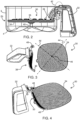
- Figure 2 shows an example of the lower section 2b of the cooking chamber with the accessory 30 suspended by its handle 32 above the base 4 of the cooking chamber.
- the handle 32 supports a perforated base 34 on which a food item 36 such as a pizza may be placed.
- the perforated base 34 is open all around, and thus comprises a generally planar support plate. It is removably attached to the handle 32 by a connection arrangement 38.
- This connection arrangement 38 creates a local side wall portion, but it is sufficiently narrow that the remaining area around the perforated base is open around at least 200 degrees.
- the outer edge of the perforated base is spaced from the inner wall of the inner sidewalls 3 of the cooking chamber 2. For example, the spacing around the outer edge (i.e. around the open region of the perforated base) when the accessory is in position within the cooking chamber may be at least 5mm, or at least 10mm.
- the perforated base may be fully supported by the handle, or there may be a support element 40 so that the perforated base also rests on the base 4 of the cooking chamber.
- the perforated base is for example mounted at least 1.5cm above the base of the cooking chamber, for example 2cm above, for example in the range 1.5cm to 5cm above the base.
- the handle 32 supports the perforated base 34 and it also clips to the lower part 2b of the cooking chamber, for example at the connection area 42.
- a single handle 32 is used to hold the lower part of the cooking chamber and the perforated base as a single connected unit.
- FIG 3 shows the perforated base 34 and the handle 32 separated.
- the perforated base 34 has the same shape as the outer contour of the cooking chamber. This is for example generally square with sharply rounded corners and gently curved sides. It thus has two diagonals 44 and four sides between the diagonals. The diagonal is a locally maximum width passing through the center of area 46.
- connection arrangement comprises two connectors 48 for connecting to the perforated base at two adjacent corners. By connecting at regions of locally maximum diameter, the circular pizza size which can be fitted on the perforated base is not reduced by the connection arrangement 38.
- the handle comprises an opening 50 (most clearly seen in Figure 5 ) between the two connectors 48.
- the perforated base preferably has a minimum diameter (e.g. from the middle of one side to the middle of an opposing side) of at least 20cm in one example and at least 26cm in another example. Standard sizes of circular pizza of 20cm or 26cm diameter are thereby able to fit on the perforated base.
- Figure 4 shows the perforated base 34 connected to the handle 32. It can then be clipped over the outer wall of the lower portion 2b of the cooking chamber to create the connected assembly of Figure 2 .
- Figure 5 shows the accessory and lower portion of the cooking chamber in plan view on the left and in end view on the right. It shows the pizza 36 as circular. It also shows that a part 52 of the pizza extends through the opening 50 so that the handle and its connection to the perforated base does not impact the maximum pizza size. It also shows that the pizza may overlap the perforated base where the perforated base has its narrowest diameter. Thus, the pizza may be slightly larger than the minimum diameter of the perforated base.
- FIG 6 shows a modification to the design of Figure 2 in which a top plate 60 is mounted above the perforated base 34 and supported by the handle 32.
- This top plate may be used to protect the heating element 18 ( Figure 1 ) above the cooking chamber from being contacted by light weight food items on the pizza which may be lifted by the air flows. It may also be used to adjust the air flow dynamics in the cooking chamber, for example reducing the airflow directly above the pizza.
- the top plate may comprise a solid plate or another perforated plate.
- a smaller solid plate may be used or a larger grid plate.
- a grid may for example have a combined area of openings which is at least 50% of the total area.
- the holes should have a small size to act as a filter to any small food items which have become caught in the air flow, for example with a diameter less than 1cm.
- Figure 7 shows the assembly of the handle 32, perforated base 34 and top plate 60 in perspective view.
- the top plate may be mountable at different heights above the perforated base, for example in steps of between 1cm and 2cm.
- a set of attachment features may for example be provided at different heights, and the top plate may be mounted to any chosen one of these attachment features.
- the top plate is for example mounted with a maximum height h of at least 7cm above the perforated base. This allows a thick pizza to be mounted between the perforated base and the top plate.
- the top plate for example has a maximum diameter of at least 15 cm. In the case of a grid, it may have the same size and shape as the perforated base as shown in Figure 7 .
- An air-based fryer generally includes the basket as the main cooking chamber accessory.
- the basket has a removable bottom part, for cleaning purposes, as mentioned above.
- the accessory may make use of the same bottom part.
- the perforated base 34 may comprise the bottom part of the main basket.
- the basic accessory of Figures 3 and 4 may be implemented only with the specially designed handle.
- the accessory with both top plate and perforated base of Figure 7 may be implemented only with the specially designed handle and one extra plate to be used as the top plate.
- top plate 60 may be interchangeable with the bottom of the main basket.
- the accessory with both top plate and perforated base may be implemented only with the specially designed handle and one extra plate to be used as the perforated base.
- top plate and the perforated base may be identical. This makes assembly easier.
- the invention may be applied to different types of air-based fryer, of which Figure 1 is only one example.
- a computer program may be stored/distributed on a suitable medium, such as an optical storage medium or a solid-state medium supplied together with or as part of other hardware, but may also be distributed in other forms, such as via the Internet or other wired or wireless telecommunication systems. Any reference signs in the claims should not be construed as limiting the scope.
Landscapes
- Engineering & Computer Science (AREA)
- Food Science & Technology (AREA)
- Life Sciences & Earth Sciences (AREA)
- Frying-Pans Or Fryers (AREA)
- Baking, Grill, Roasting (AREA)
- Cookers (AREA)
Claims (13)
- Zubehör (30) für eine luftbasierte Fritteuse, umfassend:eine luftdurchlässige perforierte Basis (34) mit einer offenen Seite um mindestens 200 Grad, wobei die perforierte Basis eine Halterung zum Tragen einer Pizza zum Backen in der luftbasierten Fritteuse umfasst, wobei die offene Seite dazu dient, um zu ermöglichen, Luft um die äußere Kruste der Pizza zu strömen; und wobei die perforierte Basis (34) nicht kreisförmig ist;einen Griff (32) zum Montieren der perforierten Basis in einer Garkammer (2) der luftbasierten Fritteuse, wobei die perforierte Basis über einer Basis (4) der Garkammer aufgehängt ist, wobei das Zubehör dadurch gekennzeichnet ist, dass der Griff (32) zwei Verbinder (48) und eine dazwischenliegende Öffnung (50) mit zwei Diagonalen (44) und vier Seiten zwischen den Diagonalen umfasst, wobei die beiden Verbinder (48) zum Verbinden des Griffs mit der perforierten Basis an zwei Stellen in der Nähe zweier benachbarter Diagonalen angeordnet sind.
- Zubehör nach Anspruch 1, wobei die perforierte Basis (34) vom Griff (32) abnehmbar ist.
- Zubehör nach einem der Ansprüche 1 bis 2, wobei die perforierte Basis (34) einen Mindestdurchmesser von mindestens 20 cm, beispielsweise mindestens 26 cm, aufweist.
- Zubehör nach einem der Ansprüche 1 bis 2, das weiter eine obere Platte (60) umfasst, die über der perforierten Basis montierbar ist, die vom Griff (32) getragen wird.
- Zubehör nach Anspruch 4, wobei die obere Platte eine massive Platte oder eine perforierte Platte umfasst.
- Zubehör nach Anspruch 4, wobei die obere Platte (60) ein Gitter umfasst, das eine kombinierte Fläche mit Öffnungen aufweist, die mindestens 50 % der Gesamtfläche beträgt.
- Zubehör nach Anspruch 4, wobei der Griff (32) Mittel zum Tragen der oberen Platte (60), zur Auswahl für einen Benutzer, in verschiedenen Höhen über der perforierten Basis (34) umfasst.
- Zubehör nach Anspruch 4, wobei die obere Platte (60) mit einer maximalen Höhe von mindestens 7 cm über der perforierten Basis montierbar ist.
- Zubehör nach einem der Ansprüche 5-8, wobei die obere Platte (60) vom Griff (32) abnehmbar ist.
- Luftbasierte Fritteuse, umfassend:eine Garkammer (2);eine Nahrungsmittelaufnahmeeinheit, die angepasst ist, um abnehmbar in der Garkammer (2) aufgenommen zu werden, sodass rund um die Nahrungsmittelaufnahmeeinheit ein Luftdurchgang (16a, 16b) gebildet wird;einen Heizer (18) zum Erhitzen von Luft in der Garkammer; undeinen Lüfter (17) zum Zirkulieren eines Heißluftstroms in der Garkammer durch den Luftdurchgang hindurch um die Nahrungsmittelaufnahmeeinheit herum,wobei die Nahrungsaufnahmeeinheit ein Zubehör (30) nach einem der Ansprüche 1 bis 9 umfasst.
- Luftbasierte Fritteuse nach Anspruch 10, wobei die perforierte Basis (34) mindestens 1,5 cm über der Basis der Garkammer montiert ist.
- Luftbasierte Fritteuse nach Anspruch 10 oder 11, die weiter eine Nahrungsmittelaufnahmekammer (10) zur Verwendung als zweite Nahrungsmittelaufnahmeeinheit umfasst, wobei die Nahrungsmittelaufnahmekammer (10) eine Seitenwand (14) umfasst, wobei die perforierte Basis (34) des Zubehörs (30) als Basis der Nahrungsmittelaufnahmekammer konfigurierbar ist, sodass die Basis (12) der Nahrungsmittelaufnahmekammer mit der perforierten Basis am Zubehör austauschbar ist.
- Luftbasierte Fritteuse nach Anspruch 12, wobei das Zubehör weiter eine obere Platte (60) umfasst, wobei die Basis (12) der Nahrungsmittelaufnahmekammer (10) mit der oberen Platte (60) des Zubehörs austauschbar ist.
Applications Claiming Priority (2)
| Application Number | Priority Date | Filing Date | Title |
|---|---|---|---|
| EP18177066.0A EP3581075A1 (de) | 2018-06-11 | 2018-06-11 | Luftbasierte fritteuse und zubehör für eine luftbasierte fritteuse |
| PCT/EP2019/065073 WO2019238605A1 (en) | 2018-06-11 | 2019-06-10 | Air-based fryer and accessory for an air-based fryer |
Publications (2)
| Publication Number | Publication Date |
|---|---|
| EP3801153A1 EP3801153A1 (de) | 2021-04-14 |
| EP3801153B1 true EP3801153B1 (de) | 2025-05-14 |
Family
ID=62599512
Family Applications (2)
| Application Number | Title | Priority Date | Filing Date |
|---|---|---|---|
| EP18177066.0A Withdrawn EP3581075A1 (de) | 2018-06-11 | 2018-06-11 | Luftbasierte fritteuse und zubehör für eine luftbasierte fritteuse |
| EP19728714.7A Active EP3801153B1 (de) | 2018-06-11 | 2019-06-10 | Luftbasierte fritteuse und zubehör für eine luftbasierte fritteuse |
Family Applications Before (1)
| Application Number | Title | Priority Date | Filing Date |
|---|---|---|---|
| EP18177066.0A Withdrawn EP3581075A1 (de) | 2018-06-11 | 2018-06-11 | Luftbasierte fritteuse und zubehör für eine luftbasierte fritteuse |
Country Status (5)
| Country | Link |
|---|---|
| US (1) | US12364361B2 (de) |
| EP (2) | EP3581075A1 (de) |
| CN (1) | CN112236062A (de) |
| PL (1) | PL3801153T3 (de) |
| WO (1) | WO2019238605A1 (de) |
Families Citing this family (11)
| Publication number | Priority date | Publication date | Assignee | Title |
|---|---|---|---|---|
| CN110200516A (zh) | 2017-08-09 | 2019-09-06 | 沙克忍者运营有限责任公司 | 烹饪系统 |
| WO2020176477A1 (en) | 2019-02-25 | 2020-09-03 | Sharkninja Operating Llc | Cooking system with guard |
| US11033146B2 (en) | 2019-02-25 | 2021-06-15 | Sharkninja Operating Llc | Cooking device and components thereof |
| CN113133684B (zh) * | 2020-01-17 | 2023-10-24 | 广东美的生活电器制造有限公司 | 空气炸锅 |
| NL2024781B1 (en) * | 2020-01-28 | 2021-09-09 | Kavaring Cooking Systems B V | Airfrying system and method |
| US11647861B2 (en) | 2020-03-30 | 2023-05-16 | Sharkninja Operating Llc | Cooking device and components thereof |
| CN218105649U (zh) * | 2022-02-16 | 2022-12-23 | 广东美的生活电器制造有限公司 | 烹饪器具 |
| US11882961B1 (en) | 2023-01-18 | 2024-01-30 | Sharkninja Operating Llc | Cover plate for cooking devices |
| CN118787254A (zh) * | 2023-04-14 | 2024-10-18 | 佛山市顺德区美的电热电器制造有限公司 | 空气炸锅 |
| US20260114666A1 (en) * | 2023-05-11 | 2026-04-30 | Versuni Holding B.V. | Air fryer comprising a food support |
| KR20260000377U (ko) | 2023-08-01 | 2026-03-13 | 샤크닌자 오퍼레이팅 엘엘씨 | 조리 기기 및 그 구성요소 |
Citations (1)
| Publication number | Priority date | Publication date | Assignee | Title |
|---|---|---|---|---|
| KR20050063946A (ko) * | 2003-12-23 | 2005-06-29 | 주식회사 대우일렉트로닉스 | 피자오븐 겸용 전자레인지 |
Family Cites Families (40)
| Publication number | Priority date | Publication date | Assignee | Title |
|---|---|---|---|---|
| US4176591A (en) | 1978-04-10 | 1979-12-04 | Power Douglas P | Cooking pan for baking pizza pies and like food products |
| US4367243A (en) | 1980-11-03 | 1983-01-04 | Pizza Hut, Inc. | Method for preparing cooking pizza |
| US4345516A (en) | 1981-02-06 | 1982-08-24 | Sinclair Lawrence L | Cooking and cutting implement |
| US4622231A (en) * | 1982-03-08 | 1986-11-11 | Idea Network Company, Inc. | Convection food heating |
| US4728762A (en) | 1984-03-22 | 1988-03-01 | Howard Roth | Microwave heating apparatus and method |
| US5206045A (en) * | 1986-05-23 | 1993-04-27 | Marshall Air Systems, Inc. | Apparatus and method for cooking food products |
| US4817509A (en) * | 1987-02-17 | 1989-04-04 | Alternative Pioneering Systems Inc. | Air Fryer |
| US5699722A (en) * | 1989-03-17 | 1997-12-23 | Erickson; Chad | Rapid cooking device |
| US5012071A (en) | 1989-11-14 | 1991-04-30 | Lincoln Foodservice Products, Inc. | Grease splatter capture shield |
| US5355868A (en) * | 1993-06-04 | 1994-10-18 | Greene Manufacturing Co. | Heat distribution article for cooking grills |
| KR200207275Y1 (ko) * | 2000-06-23 | 2000-12-15 | 장기영 | 훈제 구이기 |
| US6640695B2 (en) * | 2002-02-07 | 2003-11-04 | Steven Stark | Pizza insert for barbeque grill |
| US9351495B2 (en) * | 2002-07-05 | 2016-05-31 | Turbochef Technologies, Inc. | Air fryer |
| US20040253348A1 (en) * | 2003-04-07 | 2004-12-16 | Woodward Steven J. | Shield for food product |
| EP1867264A1 (de) * | 2006-06-16 | 2007-12-19 | Kavaring Cooking Systems B.V. i.o. | Gerät zur Behandlung von Lebensmitteln |
| US7861705B2 (en) * | 2008-02-12 | 2011-01-04 | Hulsey William C | Vertical food smoker/cooker |
| IT1390860B1 (it) * | 2008-09-29 | 2011-10-19 | De Longhi Spa | Friggitrice e procedimento di cottura |
| US8230779B2 (en) * | 2008-10-14 | 2012-07-31 | Hamilton Beach Brands, Inc. | Deep fryer for cooking foodstuff |
| US8469419B2 (en) * | 2011-08-19 | 2013-06-25 | John Archer Chapin | Pizza peel |
| US9016191B2 (en) * | 2012-04-20 | 2015-04-28 | Robert S. Krolick | Portable baking oven |
| CN102973096A (zh) * | 2012-11-14 | 2013-03-20 | 邹镇孟 | 勺子 |
| EP3590398B1 (de) | 2013-06-04 | 2023-09-27 | Koninklijke Philips N.V. | Pfanne für luftfriteuse |
| KR101696449B1 (ko) * | 2014-05-23 | 2017-01-13 | 코닌클리케 필립스 엔.브이. | 에어계 프라이어에서 연기를 감소시키기 위한 덮개 |
| US10966568B2 (en) * | 2014-09-17 | 2021-04-06 | Koninklijke Philips N.V. | Air-based fryer apparatus for preparing food |
| RU2700959C2 (ru) * | 2015-06-29 | 2019-09-24 | Конинклейке Филипс Н.В. | Съемное соединительное приспособление для прикрепления ручки к посуде |
| CN104983318A (zh) | 2015-07-07 | 2015-10-21 | 佛山市谦中益电器科技有限公司 | 一种可制作面包空气炸锅 |
| EP3386357B1 (de) | 2015-12-07 | 2024-02-07 | Koninklijke Philips N.V. | Abschirmung für luftbasierte frittiergerät |
| US20170231430A1 (en) * | 2016-02-12 | 2017-08-17 | Nuwave, Llc | Air Fryer |
| US10575680B2 (en) | 2016-02-22 | 2020-03-03 | William Rowzee Fagg | Brick pizza oven with rotatable and height adjustable turntable and conversion kit for grills |
| CN105595858B (zh) * | 2016-02-26 | 2017-12-29 | 宁波比依电器有限公司 | 空气炸锅 |
| US20190082885A1 (en) * | 2016-03-09 | 2019-03-21 | Koninklijke Philips N.V. | An air-frying cooker and a method of cleaning an air-frying cooker |
| ITUA20163617A1 (it) * | 2016-05-19 | 2017-11-19 | Tecnodom S P A | Teglia per cottura |
| US12329314B2 (en) * | 2016-06-15 | 2025-06-17 | Koninklijke Philips N.V. | Air-frying cooker |
| CN206371935U (zh) * | 2016-10-13 | 2017-08-04 | 九阳股份有限公司 | 一种便于清洗的空气炸锅 |
| WO2019000019A1 (en) * | 2017-06-30 | 2019-01-03 | Breville Pty Limited | An appliance to cook pizza |
| US12077347B2 (en) * | 2019-01-16 | 2024-09-03 | Congruens Group, Llc | Closure and drainage for food containers and food supports |
| WO2020176477A1 (en) * | 2019-02-25 | 2020-09-03 | Sharkninja Operating Llc | Cooking system with guard |
| US11918143B2 (en) * | 2020-11-06 | 2024-03-05 | Midea Group Co., Ltd. | Method and apparatus for a cooking appliance |
| WO2022271487A1 (en) * | 2021-06-21 | 2022-12-29 | Alto-Shaam, Inc. | Combination oven with independent steam generation element |
| CN121218913A (zh) * | 2023-05-05 | 2025-12-26 | 尚科宁家运营有限公司 | 烹饪装置、方法及其部件 |
-
2018
- 2018-06-11 EP EP18177066.0A patent/EP3581075A1/de not_active Withdrawn
-
2019
- 2019-06-10 EP EP19728714.7A patent/EP3801153B1/de active Active
- 2019-06-10 CN CN201980039131.1A patent/CN112236062A/zh active Pending
- 2019-06-10 PL PL19728714.7T patent/PL3801153T3/pl unknown
- 2019-06-10 US US15/733,908 patent/US12364361B2/en active Active
- 2019-06-10 WO PCT/EP2019/065073 patent/WO2019238605A1/en not_active Ceased
Patent Citations (1)
| Publication number | Priority date | Publication date | Assignee | Title |
|---|---|---|---|---|
| KR20050063946A (ko) * | 2003-12-23 | 2005-06-29 | 주식회사 대우일렉트로닉스 | 피자오븐 겸용 전자레인지 |
Also Published As
| Publication number | Publication date |
|---|---|
| EP3801153A1 (de) | 2021-04-14 |
| EP3581075A1 (de) | 2019-12-18 |
| WO2019238605A1 (en) | 2019-12-19 |
| US12364361B2 (en) | 2025-07-22 |
| US20210219777A1 (en) | 2021-07-22 |
| PL3801153T3 (pl) | 2025-07-28 |
| CN112236062A (zh) | 2021-01-15 |
Similar Documents
| Publication | Publication Date | Title |
|---|---|---|
| US12364361B2 (en) | Air-based fryer and accessory for an air-based fryer | |
| EP3806701B1 (de) | Luftbasierte fritteuse | |
| NL2020842B1 (en) | Food support for an air based fryer and air-based fryer provided with such food support | |
| EP3046451B1 (de) | Deckel für luftbasiertes fritiergerät | |
| US6293271B1 (en) | Multifunctional cooking pot | |
| US6187359B1 (en) | Method and apparatus for baking foods in a barbeque grill | |
| EP3003105B1 (de) | Luftfriteusepfanne | |
| US20080169281A1 (en) | Deep Fryer for Cooking Foodstuff | |
| WO2009126237A2 (en) | Food steamer | |
| CN205697271U (zh) | 烹饪附件和包括烹饪附件的电烹饪设备 | |
| CN213129184U (zh) | 用于基于空气的炸锅的附件,以及基于空气的炸锅 | |
| CN210249574U (zh) | 烤架及空气炸锅 | |
| CN213551311U (zh) | 炸篮组件和烹饪器具 | |
| CN210446756U (zh) | 烤架及空气炸锅 | |
| CN113854856A (zh) | 包含空气炸功能的烹饪设备 | |
| AU2023343801B2 (en) | Air fryer food support | |
| JP4000526B2 (ja) | 加熱調理器 | |
| CN213345363U (zh) | 一种空气炸篮 | |
| RU2786582C2 (ru) | Аэрофритюрница | |
| CN211155321U (zh) | 烹饪器具 | |
| CN119012949A (zh) | 具有改进的热空气输送的烹饪装置 | |
| US20180153339A1 (en) | Microwave bacon cooker with lid | |
| CA2110958A1 (en) | Convection broiler |
Legal Events
| Date | Code | Title | Description |
|---|---|---|---|
| STAA | Information on the status of an ep patent application or granted ep patent |
Free format text: STATUS: UNKNOWN |
|
| STAA | Information on the status of an ep patent application or granted ep patent |
Free format text: STATUS: THE INTERNATIONAL PUBLICATION HAS BEEN MADE |
|
| PUAI | Public reference made under article 153(3) epc to a published international application that has entered the european phase |
Free format text: ORIGINAL CODE: 0009012 |
|
| STAA | Information on the status of an ep patent application or granted ep patent |
Free format text: STATUS: REQUEST FOR EXAMINATION WAS MADE |
|
| 17P | Request for examination filed |
Effective date: 20210111 |
|
| AK | Designated contracting states |
Kind code of ref document: A1 Designated state(s): AL AT BE BG CH CY CZ DE DK EE ES FI FR GB GR HR HU IE IS IT LI LT LU LV MC MK MT NL NO PL PT RO RS SE SI SK SM TR |
|
| AX | Request for extension of the european patent |
Extension state: BA ME |
|
| DAV | Request for validation of the european patent (deleted) | ||
| DAX | Request for extension of the european patent (deleted) | ||
| STAA | Information on the status of an ep patent application or granted ep patent |
Free format text: STATUS: EXAMINATION IS IN PROGRESS |
|
| 17Q | First examination report despatched |
Effective date: 20240207 |
|
| RAP1 | Party data changed (applicant data changed or rights of an application transferred) |
Owner name: VERSUNI HOLDING B.V. |
|
| GRAP | Despatch of communication of intention to grant a patent |
Free format text: ORIGINAL CODE: EPIDOSNIGR1 |
|
| STAA | Information on the status of an ep patent application or granted ep patent |
Free format text: STATUS: GRANT OF PATENT IS INTENDED |
|
| GRAS | Grant fee paid |
Free format text: ORIGINAL CODE: EPIDOSNIGR3 |
|
| INTG | Intention to grant announced |
Effective date: 20250306 |
|
| GRAA | (expected) grant |
Free format text: ORIGINAL CODE: 0009210 |
|
| STAA | Information on the status of an ep patent application or granted ep patent |
Free format text: STATUS: THE PATENT HAS BEEN GRANTED |
|
| AK | Designated contracting states |
Kind code of ref document: B1 Designated state(s): AL AT BE BG CH CY CZ DE DK EE ES FI FR GB GR HR HU IE IS IT LI LT LU LV MC MK MT NL NO PL PT RO RS SE SI SK SM TR |
|
| REG | Reference to a national code |
Ref country code: GB Ref legal event code: FG4D |
|
| REG | Reference to a national code |
Ref country code: CH Ref legal event code: EP |
|
| REG | Reference to a national code |
Ref country code: IE Ref legal event code: FG4D |
|
| REG | Reference to a national code |
Ref country code: DE Ref legal event code: R096 Ref document number: 602019069949 Country of ref document: DE |
|
| P01 | Opt-out of the competence of the unified patent court (upc) registered |
Free format text: CASE NUMBER: APP_22084/2025 Effective date: 20250509 |
|
| REG | Reference to a national code |
Ref country code: NL Ref legal event code: FP |
|
| PGFP | Annual fee paid to national office [announced via postgrant information from national office to epo] |
Ref country code: DE Payment date: 20250626 Year of fee payment: 7 |
|
| PGFP | Annual fee paid to national office [announced via postgrant information from national office to epo] |
Ref country code: NL Payment date: 20250624 Year of fee payment: 7 |
|
| PG25 | Lapsed in a contracting state [announced via postgrant information from national office to epo] |
Ref country code: PT Free format text: LAPSE BECAUSE OF FAILURE TO SUBMIT A TRANSLATION OF THE DESCRIPTION OR TO PAY THE FEE WITHIN THE PRESCRIBED TIME-LIMIT Effective date: 20250915 Ref country code: FI Free format text: LAPSE BECAUSE OF FAILURE TO SUBMIT A TRANSLATION OF THE DESCRIPTION OR TO PAY THE FEE WITHIN THE PRESCRIBED TIME-LIMIT Effective date: 20250514 Ref country code: ES Free format text: LAPSE BECAUSE OF FAILURE TO SUBMIT A TRANSLATION OF THE DESCRIPTION OR TO PAY THE FEE WITHIN THE PRESCRIBED TIME-LIMIT Effective date: 20250514 |
|
| REG | Reference to a national code |
Ref country code: LT Ref legal event code: MG9D |
|
| PG25 | Lapsed in a contracting state [announced via postgrant information from national office to epo] |
Ref country code: NO Free format text: LAPSE BECAUSE OF FAILURE TO SUBMIT A TRANSLATION OF THE DESCRIPTION OR TO PAY THE FEE WITHIN THE PRESCRIBED TIME-LIMIT Effective date: 20250814 Ref country code: GR Free format text: LAPSE BECAUSE OF FAILURE TO SUBMIT A TRANSLATION OF THE DESCRIPTION OR TO PAY THE FEE WITHIN THE PRESCRIBED TIME-LIMIT Effective date: 20250815 |
|
| PGFP | Annual fee paid to national office [announced via postgrant information from national office to epo] |
Ref country code: TR Payment date: 20250711 Year of fee payment: 7 Ref country code: PL Payment date: 20250613 Year of fee payment: 7 |
|
| REG | Reference to a national code |
Ref country code: AT Ref legal event code: MK05 Ref document number: 1794068 Country of ref document: AT Kind code of ref document: T Effective date: 20250514 |
|
| PG25 | Lapsed in a contracting state [announced via postgrant information from national office to epo] |
Ref country code: BG Free format text: LAPSE BECAUSE OF FAILURE TO SUBMIT A TRANSLATION OF THE DESCRIPTION OR TO PAY THE FEE WITHIN THE PRESCRIBED TIME-LIMIT Effective date: 20250514 |
|
| PG25 | Lapsed in a contracting state [announced via postgrant information from national office to epo] |
Ref country code: HR Free format text: LAPSE BECAUSE OF FAILURE TO SUBMIT A TRANSLATION OF THE DESCRIPTION OR TO PAY THE FEE WITHIN THE PRESCRIBED TIME-LIMIT Effective date: 20250514 |
|
| PG25 | Lapsed in a contracting state [announced via postgrant information from national office to epo] |
Ref country code: AT Free format text: LAPSE BECAUSE OF FAILURE TO SUBMIT A TRANSLATION OF THE DESCRIPTION OR TO PAY THE FEE WITHIN THE PRESCRIBED TIME-LIMIT Effective date: 20250514 |
|
| PG25 | Lapsed in a contracting state [announced via postgrant information from national office to epo] |
Ref country code: RS Free format text: LAPSE BECAUSE OF FAILURE TO SUBMIT A TRANSLATION OF THE DESCRIPTION OR TO PAY THE FEE WITHIN THE PRESCRIBED TIME-LIMIT Effective date: 20250814 |
|
| PG25 | Lapsed in a contracting state [announced via postgrant information from national office to epo] |
Ref country code: IS Free format text: LAPSE BECAUSE OF FAILURE TO SUBMIT A TRANSLATION OF THE DESCRIPTION OR TO PAY THE FEE WITHIN THE PRESCRIBED TIME-LIMIT Effective date: 20250914 |
|
| PG25 | Lapsed in a contracting state [announced via postgrant information from national office to epo] |
Ref country code: LV Free format text: LAPSE BECAUSE OF FAILURE TO SUBMIT A TRANSLATION OF THE DESCRIPTION OR TO PAY THE FEE WITHIN THE PRESCRIBED TIME-LIMIT Effective date: 20250514 |
|
| PG25 | Lapsed in a contracting state [announced via postgrant information from national office to epo] |
Ref country code: SM Free format text: LAPSE BECAUSE OF FAILURE TO SUBMIT A TRANSLATION OF THE DESCRIPTION OR TO PAY THE FEE WITHIN THE PRESCRIBED TIME-LIMIT Effective date: 20250514 Ref country code: DK Free format text: LAPSE BECAUSE OF FAILURE TO SUBMIT A TRANSLATION OF THE DESCRIPTION OR TO PAY THE FEE WITHIN THE PRESCRIBED TIME-LIMIT Effective date: 20250514 |
|
| PG25 | Lapsed in a contracting state [announced via postgrant information from national office to epo] |
Ref country code: CZ Free format text: LAPSE BECAUSE OF FAILURE TO SUBMIT A TRANSLATION OF THE DESCRIPTION OR TO PAY THE FEE WITHIN THE PRESCRIBED TIME-LIMIT Effective date: 20250514 |
|
| PG25 | Lapsed in a contracting state [announced via postgrant information from national office to epo] |
Ref country code: EE Free format text: LAPSE BECAUSE OF FAILURE TO SUBMIT A TRANSLATION OF THE DESCRIPTION OR TO PAY THE FEE WITHIN THE PRESCRIBED TIME-LIMIT Effective date: 20250514 |
|
| PG25 | Lapsed in a contracting state [announced via postgrant information from national office to epo] |
Ref country code: RO Free format text: LAPSE BECAUSE OF FAILURE TO SUBMIT A TRANSLATION OF THE DESCRIPTION OR TO PAY THE FEE WITHIN THE PRESCRIBED TIME-LIMIT Effective date: 20250514 Ref country code: SK Free format text: LAPSE BECAUSE OF FAILURE TO SUBMIT A TRANSLATION OF THE DESCRIPTION OR TO PAY THE FEE WITHIN THE PRESCRIBED TIME-LIMIT Effective date: 20250514 |
|
| REG | Reference to a national code |
Ref country code: CH Ref legal event code: H13 Free format text: ST27 STATUS EVENT CODE: U-0-0-H10-H13 (AS PROVIDED BY THE NATIONAL OFFICE) Effective date: 20260127 |
|
| PG25 | Lapsed in a contracting state [announced via postgrant information from national office to epo] |
Ref country code: IT Free format text: LAPSE BECAUSE OF FAILURE TO SUBMIT A TRANSLATION OF THE DESCRIPTION OR TO PAY THE FEE WITHIN THE PRESCRIBED TIME-LIMIT Effective date: 20250514 |
|
| PG25 | Lapsed in a contracting state [announced via postgrant information from national office to epo] |
Ref country code: LU Free format text: LAPSE BECAUSE OF NON-PAYMENT OF DUE FEES Effective date: 20250610 |
|
| REG | Reference to a national code |
Ref country code: DE Ref legal event code: R097 Ref document number: 602019069949 Country of ref document: DE |
|
| PG25 | Lapsed in a contracting state [announced via postgrant information from national office to epo] |
Ref country code: MC Free format text: LAPSE BECAUSE OF FAILURE TO SUBMIT A TRANSLATION OF THE DESCRIPTION OR TO PAY THE FEE WITHIN THE PRESCRIBED TIME-LIMIT Effective date: 20250514 |
|
| REG | Reference to a national code |
Ref country code: BE Ref legal event code: MM Effective date: 20250630 |
|
| PLBE | No opposition filed within time limit |
Free format text: ORIGINAL CODE: 0009261 |
|
| STAA | Information on the status of an ep patent application or granted ep patent |
Free format text: STATUS: NO OPPOSITION FILED WITHIN TIME LIMIT |
|
| REG | Reference to a national code |
Ref country code: CH Ref legal event code: L10 Free format text: ST27 STATUS EVENT CODE: U-0-0-L10-L00 (AS PROVIDED BY THE NATIONAL OFFICE) Effective date: 20260325 |
|
| PG25 | Lapsed in a contracting state [announced via postgrant information from national office to epo] |
Ref country code: IE Free format text: LAPSE BECAUSE OF NON-PAYMENT OF DUE FEES Effective date: 20250610 |
|
| PG25 | Lapsed in a contracting state [announced via postgrant information from national office to epo] |
Ref country code: BE Free format text: LAPSE BECAUSE OF NON-PAYMENT OF DUE FEES Effective date: 20250630 |
|
| PG25 | Lapsed in a contracting state [announced via postgrant information from national office to epo] |
Ref country code: FR Free format text: LAPSE BECAUSE OF NON-PAYMENT OF DUE FEES Effective date: 20250714 |
|
| 26N | No opposition filed |
Effective date: 20260217 |
|
| PG25 | Lapsed in a contracting state [announced via postgrant information from national office to epo] |
Ref country code: CH Free format text: LAPSE BECAUSE OF NON-PAYMENT OF DUE FEES Effective date: 20250630 |
|
| GBPC | Gb: european patent ceased through non-payment of renewal fee |
Effective date: 20250814 |