EP3800747B1 - Kabelgebundenes reinigungsgerät - Google Patents
Kabelgebundenes reinigungsgerät Download PDFInfo
- Publication number
- EP3800747B1 EP3800747B1 EP20196140.6A EP20196140A EP3800747B1 EP 3800747 B1 EP3800747 B1 EP 3800747B1 EP 20196140 A EP20196140 A EP 20196140A EP 3800747 B1 EP3800747 B1 EP 3800747B1
- Authority
- EP
- European Patent Office
- Prior art keywords
- connection part
- connector
- locking
- plug connector
- corded
- Prior art date
- Legal status (The legal status is an assumption and is not a legal conclusion. Google has not performed a legal analysis and makes no representation as to the accuracy of the status listed.)
- Active
Links
Images




Classifications
-
- H—ELECTRICITY
- H01—ELECTRIC ELEMENTS
- H01R—ELECTRICALLY-CONDUCTIVE CONNECTIONS; STRUCTURAL ASSOCIATIONS OF A PLURALITY OF MUTUALLY-INSULATED ELECTRICAL CONNECTING ELEMENTS; COUPLING DEVICES; CURRENT COLLECTORS
- H01R35/00—Flexible or turnable line connectors, i.e. the rotation angle being limited
- H01R35/02—Flexible line connectors without frictional contact members
-
- A—HUMAN NECESSITIES
- A47—FURNITURE; DOMESTIC ARTICLES OR APPLIANCES; COFFEE MILLS; SPICE MILLS; SUCTION CLEANERS IN GENERAL
- A47L—DOMESTIC WASHING OR CLEANING; SUCTION CLEANERS IN GENERAL
- A47L5/00—Structural features of suction cleaners
- A47L5/12—Structural features of suction cleaners with power-driven air-pumps or air-compressors, e.g. driven by motor vehicle engine vacuum
- A47L5/22—Structural features of suction cleaners with power-driven air-pumps or air-compressors, e.g. driven by motor vehicle engine vacuum with rotary fans
- A47L5/36—Suction cleaners with hose between nozzle and casing; Suction cleaners for fixing on staircases; Suction cleaners for carrying on the back
- A47L5/365—Suction cleaners with hose between nozzle and casing; Suction cleaners for fixing on staircases; Suction cleaners for carrying on the back of the vertical type, e.g. tank or bucket type
-
- A—HUMAN NECESSITIES
- A47—FURNITURE; DOMESTIC ARTICLES OR APPLIANCES; COFFEE MILLS; SPICE MILLS; SUCTION CLEANERS IN GENERAL
- A47L—DOMESTIC WASHING OR CLEANING; SUCTION CLEANERS IN GENERAL
- A47L9/00—Details or accessories of suction cleaners, e.g. mechanical means for controlling the suction or for effecting pulsating action; Storing devices specially adapted to suction cleaners or parts thereof; Carrying-vehicles specially adapted for suction cleaners
- A47L9/26—Incorporation of winding devices for electric cables
-
- B—PERFORMING OPERATIONS; TRANSPORTING
- B65—CONVEYING; PACKING; STORING; HANDLING THIN OR FILAMENTARY MATERIAL
- B65H—HANDLING THIN OR FILAMENTARY MATERIAL, e.g. SHEETS, WEBS, CABLES
- B65H75/00—Storing webs, tapes, or filamentary material, e.g. on reels
- B65H75/02—Cores, formers, supports, or holders for coiled, wound, or folded material, e.g. reels, spindles, bobbins, cop tubes, cans, mandrels or chucks
- B65H75/18—Constructional details
- B65H75/28—Arrangements for positively securing ends of material
-
- B—PERFORMING OPERATIONS; TRANSPORTING
- B65—CONVEYING; PACKING; STORING; HANDLING THIN OR FILAMENTARY MATERIAL
- B65H—HANDLING THIN OR FILAMENTARY MATERIAL, e.g. SHEETS, WEBS, CABLES
- B65H75/00—Storing webs, tapes, or filamentary material, e.g. on reels
- B65H75/02—Cores, formers, supports, or holders for coiled, wound, or folded material, e.g. reels, spindles, bobbins, cop tubes, cans, mandrels or chucks
- B65H75/34—Cores, formers, supports, or holders for coiled, wound, or folded material, e.g. reels, spindles, bobbins, cop tubes, cans, mandrels or chucks specially adapted or mounted for storing and repeatedly paying-out and re-storing lengths of material provided for particular purposes, e.g. anchored hoses, power cables
- B65H75/38—Cores, formers, supports, or holders for coiled, wound, or folded material, e.g. reels, spindles, bobbins, cop tubes, cans, mandrels or chucks specially adapted or mounted for storing and repeatedly paying-out and re-storing lengths of material provided for particular purposes, e.g. anchored hoses, power cables involving the use of a core or former internal to, and supporting, a stored package of material
- B65H75/40—Cores, formers, supports, or holders for coiled, wound, or folded material, e.g. reels, spindles, bobbins, cop tubes, cans, mandrels or chucks specially adapted or mounted for storing and repeatedly paying-out and re-storing lengths of material provided for particular purposes, e.g. anchored hoses, power cables involving the use of a core or former internal to, and supporting, a stored package of material mobile or transportable
- B65H75/42—Cores, formers, supports, or holders for coiled, wound, or folded material, e.g. reels, spindles, bobbins, cop tubes, cans, mandrels or chucks specially adapted or mounted for storing and repeatedly paying-out and re-storing lengths of material provided for particular purposes, e.g. anchored hoses, power cables involving the use of a core or former internal to, and supporting, a stored package of material mobile or transportable attached to, or forming part of, mobile tools, machines or vehicles
-
- H—ELECTRICITY
- H01—ELECTRIC ELEMENTS
- H01R—ELECTRICALLY-CONDUCTIVE CONNECTIONS; STRUCTURAL ASSOCIATIONS OF A PLURALITY OF MUTUALLY-INSULATED ELECTRICAL CONNECTING ELEMENTS; COUPLING DEVICES; CURRENT COLLECTORS
- H01R13/00—Details of coupling devices of the kinds covered by groups H01R12/70 or H01R24/00 - H01R33/00
- H01R13/62—Means for facilitating engagement or disengagement of coupling parts or for holding them in engagement
- H01R13/639—Additional means for holding or locking coupling parts together, after engagement, e.g. separate keylock, retainer strap
-
- H—ELECTRICITY
- H01—ELECTRIC ELEMENTS
- H01R—ELECTRICALLY-CONDUCTIVE CONNECTIONS; STRUCTURAL ASSOCIATIONS OF A PLURALITY OF MUTUALLY-INSULATED ELECTRICAL CONNECTING ELEMENTS; COUPLING DEVICES; CURRENT COLLECTORS
- H01R13/00—Details of coupling devices of the kinds covered by groups H01R12/70 or H01R24/00 - H01R33/00
- H01R13/72—Means for accommodating flexible lead within the holder
-
- B—PERFORMING OPERATIONS; TRANSPORTING
- B65—CONVEYING; PACKING; STORING; HANDLING THIN OR FILAMENTARY MATERIAL
- B65H—HANDLING THIN OR FILAMENTARY MATERIAL, e.g. SHEETS, WEBS, CABLES
- B65H2402/00—Constructional details of the handling apparatus
- B65H2402/40—Details of frames, housings or mountings of the whole handling apparatus
- B65H2402/41—Portable or hand-held apparatus
- B65H2402/412—Portable or hand-held apparatus details or the parts to be hold by the user, e.g. handle
-
- B—PERFORMING OPERATIONS; TRANSPORTING
- B65—CONVEYING; PACKING; STORING; HANDLING THIN OR FILAMENTARY MATERIAL
- B65H—HANDLING THIN OR FILAMENTARY MATERIAL, e.g. SHEETS, WEBS, CABLES
- B65H2701/00—Handled material; Storage means
- B65H2701/30—Handled filamentary material
- B65H2701/34—Handled filamentary material electric cords or electric power cables
-
- H—ELECTRICITY
- H01—ELECTRIC ELEMENTS
- H01R—ELECTRICALLY-CONDUCTIVE CONNECTIONS; STRUCTURAL ASSOCIATIONS OF A PLURALITY OF MUTUALLY-INSULATED ELECTRICAL CONNECTING ELEMENTS; COUPLING DEVICES; CURRENT COLLECTORS
- H01R24/00—Two-part coupling devices, or either of their cooperating parts, characterised by their overall structure
- H01R24/20—Coupling parts carrying sockets, clips or analogous contacts and secured only to wire or cable
- H01R24/22—Coupling parts carrying sockets, clips or analogous contacts and secured only to wire or cable with additional earth or shield contacts
-
- H—ELECTRICITY
- H02—GENERATION; CONVERSION OR DISTRIBUTION OF ELECTRIC POWER
- H02G—INSTALLATION OF ELECTRIC CABLES OR LINES, OR OF COMBINED OPTICAL AND ELECTRIC CABLES OR LINES
- H02G11/00—Arrangements of electric cables or lines between relatively-movable parts
- H02G11/02—Arrangements of electric cables or lines between relatively-movable parts using take-up reel or drum
Definitions
- the invention relates to a corded tool, in particular a suction device, and a method for establishing a secure connection between a connection part of a corded tool, in particular a suction device, and a plug connector.
- Power cables of electrically operated tools can often only be replaced by a specialist.
- One end of the power cable on the device side is usually firmly connected to the working device in such a way that it can only be changed by specialist personnel using tools, for example by soldering, and/or dismantling the working device. This makes it more difficult, for example, to replace a defective power cable and leads to increased repair costs and downtime of the working device.
- the device-side end of the power cable is connected to a rotatably mounted retractor drum.
- a simple plug-in connection between the cable and the winding drum is usually not an option, since the plug-in connection cannot withstand the high tensile forces when the cable is wound up and unwound.
- Additional locking and/or strain relief devices can be provided for the cable to relieve the plug connection and/or to prevent the plug connector from being pulled out unintentionally. These are usually screwed to the housing of the tool, which makes it even more difficult to replace a defective power cable.
- the EP 3 287 060 A1 discloses a mobile working device with a winding device for a cable, such as a vacuum cleaner.
- a winding device for a cable such as a vacuum cleaner.
- an electrical plug connection is provided, which consists of a socket arranged on the cable end on the machine side and a plug arranged on a side wall of the cover part of the tool.
- the cord emanating from the connected socket 46 is routed through a radial slot.
- the U.S. 2012/0120571 A1 discloses a merchandise display security device for displaying and protecting an item of merchandise.
- the device includes a means for retaining a power adapter cable to a sensor housing when the article of merchandise is attached to the sensor housing.
- the sensor housing includes a power output connector with a tray having an outer wall formed with a groove for receiving and holding a portion of the power adapter cable.
- the portion of the power adapter cable is rotatably disposed in the groove between a plugged position in which the article of merchandise is not readily attachable to the sensor housing and a plugged and coupled position in which the item of merchandise may be attached.
- the invention is therefore based on the object of presenting a working device in which the disadvantages known from the prior art are avoided or at least reduced.
- This object is achieved by a wired tool according to the main claim, a system according to claim 12 and by a method for establishing a connection between a connection part of a wired tool and a connector according to claim 13.
- Advantageous developments are the subject matter of the dependent claims.
- the invention relates to a cable-connected working device, in particular a suction device, with an electrical connection part that can be transferred between a locking position and a release position.
- the implement or a component of the implement forms an undercut for a plug connector connected to the connecting part in the locked position.
- the invention also relates to a method for producing a secure connection between a connection part of a cable-connected tool, in particular a dry vacuum cleaner, and a plug connector, with the steps: connecting the plug connector to the electrical connection part in a release position; and transferring the connecting part from the release position into a locking position, wherein in the locking position the implement forms an undercut for the plug connector and the connecting part is transferred from the release position into the locking position by a pivoting movement of the connecting part.
- the wired working device can be, for example, a cleaning device such as a suction device, such as a dry vacuum cleaner.
- the electrical connection part is designed to establish an electrical connection.
- the electrical connector may be part of an electrical connector such as a plug or socket. Connectors are used for the reversible disconnection and connection of electrical lines. A holding force of the plugged-in electrical connection can be ensured by a positive fit of the plug connector or an additional mechanical lock.
- the connection part can be arranged at any point on the implement and/or can be arranged so that it can move with respect to the implement.
- a connector connected to the connection part is locked, i.e. the connector cannot be separated or removed from the connection part.
- the plug connection can be locked by moving the connecting part into a release position. In the release position, a connector can be connected or disconnected.
- An element of the tool is referred to as an undercut, which element protrudes in relation to the tool and thus prevents a plug connector connected to the connecting part in the locking position from being able to be separated from the connecting part.
- the cable can be an electrical cable or power cable.
- the reeling device usually includes a reeling drum for receiving the cable, which is rotatably mounted about an axis of rotation and possibly also an operating and/or actuating element, such as a manual one Hand crank, has.
- the winding device initiates a winding of the cable by a crank movement.
- An exposed end of the cord which may be fitted with a power plug, can thus be rolled up and stowed over the retractor.
- the connection part can be designed as part of the reeling drum and is thus also arranged to be rotatable about the axis of rotation of the reeling drum.
- the connection part can be designed as a movable part of the connection drum without impairing the functioning of the winding device.
- the invention is based on the finding that a plug connection can be locked via a connecting part which is arranged on the cable drum and can be transferred between a locking position and a release position, and the plug connection can thereby be secured or released in a targeted manner.
- the locking takes place via an element of the tool, referred to as an undercut, which projects in relation to the tool in such a way that the connected plug connector is fixed in the plug-in direction.
- an undercut which projects in relation to the tool in such a way that the connected plug connector is fixed in the plug-in direction.
- the release position a plug connector connected to the connection part can be removed from the connection part, while this is prevented in the locked position by the catch.
- the plug-in connection can be disconnected or connected independently by an operator and without the use of tools.
- connection part is transferred between the release position and the locking position by means of a pivoting movement.
- connection part is rotatably mounted about an axis of rotation.
- the pivoting movement can essentially take place transversely to the insertion direction of the connection part.
- a pivotably mounted connection part is, for example, by laterally shifting a connected connector (or a cable connected to it) reversibly transferred between the locking and release position.
- connection or disconnection of the plug connector can be permitted.
- the implement does not form an undercut for the connected connector.
- the plug connector can be connected to and disconnected from the connecting part by an operator, for example by plugging in or unplugging, without the aid of tools.
- the connection or disconnection of the connector can be prevented.
- the connector is fixed in the insertion direction by the undercut and cannot be removed from the connection part.
- the corded working device can have a reeling device for reeling up a cable with a reeling drum that is rotatably mounted about an axis of rotation, with the connection part being designed as part of the reeling device. Locking the plug-in connection ensures that the cable is rolled up correctly via the roll-up device and the roll-up device can be operated without restrictions.
- the connector is rotatably connected to the reel drum.
- the rotatably mounted winding drum is designed as an undercut for the plug connector connected to the connection part in the locked position.
- the pivoting movement of the connection part preferably takes place perpendicularly in the direction of the axis of rotation of the reeling drum. This avoids an unintentional pivoting of the connection part during the operation of the retractor.
- connection part In the locking position, the connection part can specify an insertion direction which runs essentially tangentially to the axis of rotation. This allows the retractor to operate properly when reeling in the connected cable.
- the undercut of the implement can be formed by at least one first locking element.
- the locking element is preferably arranged on a horizontally aligned wall section of the implement. More preferably, the locking element extends essentially transversely to the insertion direction of the connection part in the locking position. Viewed in the direction of insertion, the locking element can be at some distance from the connection part in order not to impair accessibility of the connection part in the release position.
- the locking element can be formed as part of the reel drum.
- the undercut can have a second locking element arranged opposite the first locking element.
- the opposite second locking element can be mirror-symmetrical to the first locking element.
- the locking elements are preferably placed such that a distance between the locking elements is smaller than a maximum width of the connector. The opposite arrangement of the locking elements increases the holding power of the plug connection. As a result, the plug-in connection is protected, for example during operation of the retractor, from high tensile forces acting on the plug-in connection.
- the first and/or second locking element can extend essentially transversely to the insertion direction of the connection part in the locking position. Through the alignment across the locking can be controlled by the pivoting movement of the connecting part relative to the insertion direction or essentially along the pivoting direction. By shifting the connection part into the locking position, the locking elements are placed on the connector in such a way that they fix it.
- connection part can be designed as a socket.
- the design of the connection part as a standard socket e.g. cold device socket
- the retractor can also have a hand crank for actuating the retractor.
- the winding drum can be aligned using the manual crank handle in such a way that the connection part is arranged so that it is visible and accessible to an operator.
- the tool can also have a strain relief device for the cable.
- the strain relief device can be a mechanical protection device that clamps the cable or fixes it in such a way that it is protected against being torn out.
- the invention also relates to a system made up of a corresponding corded working device and a cable with a plug connector, the plug connector having at least one taper which is designed to be essentially complementary to the undercut of the reel drum.
- the locking of the connector can be further improved by adapting the geometry of the undercut in relation to the geometry of the taper or vice versa.
- the invention also relates to a method for establishing a secure connection, in which the connection part is transferred from the release position to the locking position by a pivoting movement of the connection part.
- a simple pivoting movement By means of a simple pivoting movement, a user can lock the plug-in connection in a simple manner and without the aid of tools.
- the method according to the invention can be continued with further features described in connection with the corded working device according to the invention.
- the corded working device according to the invention can be further developed with further features described in connection with the method according to the invention.
- figure 1 12 shows a retractor 20 designed as part of a corded working device (not shown) and a separate power cable 30 with a connector 32.
- the connector 32 can be plugged into the retractor 20 (see FIG figure 2 ) and thereby provide a power supply for the retractor 20 and/or the corded cleaning device.
- the corded working device can be a cleaning device, such as a vacuum cleaner for building cleaning, such as a dry vacuum cleaner.
- a cleaning device such as a vacuum cleaner for building cleaning
- the wired cleaning device is not limited to dry vacuum cleaners, but includes, for example, vacuum cleaners of all kinds for professional and/or private use, including wet vacuum cleaners.
- a lawnmower can also be used as a working tool.
- the corded working device is not limited to a working device with a roll-up device, but is described below merely as an example in connection with a roll-up device.
- the tool has a mostly mobile housing, of which a handle 12 and a top cover 20a in the figure 1 are shown.
- a coiled cord 30 can be stowed inside the case between the top cover 20a and a bottom cover 20b.
- the winding device 20 For rolling up or winding up the cable 30, the winding device 20 has a winding drum 22, which can be rotated about an axis of rotation D (see FIG Figure 3b ) is stored.
- the axis of rotation D is perpendicular to an in figure 1 insertion direction shown (along the direction of the arrow) of the cable 30.
- the hand crank 21 By cranking the hand crank 21 about the axis of rotation D, the winding drum 22 rotates and the cable 30 is rolled up.
- the hand crank 21 rotates in the opposite direction.
- the roll-up device 20 has an electrical connection part 24 for establishing a plug-in connection with the plug-in connector 32 .
- the connection part 24 is preferably also a connector that is compatible with the Connector 32 is formed.
- the connection part 24 is designed as a (commercially available) socket in the form of a non-heating device socket, and the plug connector as a (commercially available) plug in the form of a non-heating device plug.
- the connector is also rotatably mounted around a rotation axis R (see Figure 3b ).
- the connecting part 24 is connected to the reeling drum 22 in such a way that it rotates with the reeling drum 22 when the reeling device 20 is actuated.
- the connection part 24 is movably connected to the reel drum 22 in such a way that the connection part 22 can be transferred between a release position and a locking position.
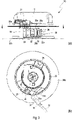
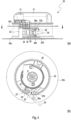
- FIG 2 shows the reeling device 20 with a connected plug connector 32.
- the reeling drum 22 has a locking element 26a, 26b on an upper wall section 22a and on a lower wall section 22b.
- the connector 32 can be locked in such a way that the locking elements 26a, 26b engage in a narrowing 33 of the connector 32 and fix it in the plug-in direction.
- figure 3 shows the connector 32 together with the cable 30 in a state separated from the connection part 24 .
- the connection part 24 is in the release position, with the insertion direction in the direction of the arrow ( Figure 3a ) is aligned.
- the connector 32 In the release position of the connection part 24, the connector 32 can be easily connected or disconnected again.
- connector 32 In figure 4 1, connector 32 is shown in a mated condition with connector 24 still positioned in the release position. Proper operation of the retractor is not readily guaranteed in the release position, since the plug connection can be separated, for example, by tensile forces that occur.
- an additional strain relief device 28 can be used to protect the cable 30 from being torn out. How from the Figures 3 and 4 As can be seen, the locking element 26a shown is not in an operative connection with the plug connector 32.
- connection part 24 is transferred into a locking position by a pivoting movement along the Figure 4b direction of the arrow shown.
- the connecting part performs a pivoting movement about the axis of rotation R.
- the pivoting movement also takes place in a plane perpendicular to the axis of rotation D of the winding drum 22.
- a pivoting movement of the connection part 24 can be produced by an operator particularly easily by laterally displacing the plug connector.
- FIG. 5 shows the connecting part 24 in the locking position with the plug connector 32 connected.
- the locking element 26a, 26b forms an undercut 26 for the plug connector 32.
- the locking element 26a, 26b can be designed to be compatible with an existing taper 33 of the plug connector be or vice versa.
- the locking element 26a, 26b is formed substantially in the direction of the pivoting direction and thus substantially transverse to the direction of insertion Connection part 24. This allows the locking element 26a, 26b to increasingly engage in the taper 33 during the pivoting movement. In other words, the plug connector 32 is increasingly pushed further onto the locking element 26a, 26b by the pivoting movement and the connection part 24 is transferred into the locking position.
- a wall section of the reel drum 22 serves as a stop 29 for the connector 32 in the locked position.
- the plug connector 32 is locked and the plug connection is prevented from being separated.
- a detent (not shown) can engage in a corresponding depression when the locking position is reached.
- connection part 24 In the locking position, the insertion direction of the connection part 24 is aligned essentially tangentially to a circular movement predetermined by the winding drum 22 . Proper operation of the retractor 20 is then ensured in the locked position. If the connector 32 is to be separated from the connection part 24, the connection part 24 must first be transferred back into the release position. This is done analogously by a pivoting movement in an opposite direction. A projection arranged on the reeling drum 22 serves as a stop 27 for the connection part 24 in the release position. In the release position of the connection part, the plug connector can then be easily separated.
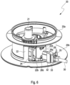
- FIGs 6 to 8 a system of the reeling device 20 and the cable 30 to be reeled up is shown again in the different states in a three-dimensional view.
- the Connector 32 is initially separated from the connection part 24 in the release position ( figure 6 ).
- figure 7 shows the connection of the connector 32 to the connection part 24 in the release position.
- the oppositely arranged locking elements 26a, 26b are not in engagement with the connector 32 in the release position and do not form an undercut for the connector 32.
- the connecting part 24 is transferred into the locking position in which the winding drum 22 forms an undercut for the connected plug connector 32 by the locking elements 26a and 26b.
- the plug connector 32 is thus locked in the plug-in direction by the locking elements extending substantially transversely to the plug-in direction.
- the connection part (24) is reversibly transferred between the release position and the locking position by a pivoting movement of the connection part (24).
- the working device also has a strain relief device 28 which clamps the cable 30 in place.
- the strain relief device 28 is designed as part of the roll-up device 20 and is arranged opposite the connection part 24 .
- the strain relief device 28 is designed in the form of a hook, which specifies a cable guide for the flexible cable 30, which prevents the cable 30 from being torn out.
- the cable 30 can be manually connected and disconnected from the strain relief device 28 by an operator.
Landscapes
- Engineering & Computer Science (AREA)
- Mechanical Engineering (AREA)
- Details Of Connecting Devices For Male And Female Coupling (AREA)
Description
- Die Erfindung betrifft ein kabelgebundenes Arbeitsgerät, insbesondere ein Sauggerät, sowie ein Verfahren zum Herstellen einer gesicherten Verbindung zwischen einem Anschlussteil eines kabelgebundenen Arbeitsgeräts, insbesondere eines Sauggeräts, und einem Steckverbinder.
- Stromkabel elektrisch betriebener Arbeitsgeräte, wie beispielsweise elektrisch betriebener Reinigungsgeräte, können häufig nur durch einen Fachmann getauscht werden. Ein geräteseitiges Ende des Stromkabels ist in der Regel derart fest mit dem Arbeitsgerät verbunden, dass es nur durch Fachpersonal unter Zuhilfenahme von Werkzeug, bspw. durch Löten, und/oder Demontage des Arbeitsgeräts gewechselt werden kann. Dies erschwert beispielsweise den Austausch eines defekten Stromkabels und führt zu erhöhten Reparaturkosten und Ausfallzeiten des Arbeitsgeräts.
- Insbesondere bei kabelgebundenen Arbeitsgeräten mit einer Aufrolleinrichtung ist das geräteseitige Ende des Stromkabels mit einer drehbar gelagerten Aufrolltrommel verbunden. Eine einfache Steckverbindung zwischen Kabel und Aufrolltrommel scheidet zumeist aus, da die Steckverbindung den hohen Zugkräften beim Auf- und Abrollen des Kabels nicht Stand hält. Zur Entlastung der Steckverbindung und/oder um ein ungewolltes Abziehen des Steckverbinders zu vermeiden, können zusätzlich Verriegelungs- und/oder Zugentlastungseinrichtungen für das Kabel vorgesehen werden. Diese sind meist mit dem Gehäuse des Arbeitsgeräts verschraubt, was den Austausch eines defekten Stromkabels zusätzlich erschwert.
- Die
EP 3 287 060 A1 offenbart ein mobiles Arbeitsgerät mit einer Aufrolleinrichtung für ein Kabel, wie bspw. einen Staubsauger. Zum Verbinden des Arbeitsgeräts mit dem Kabel ist eine elektrische Steckverbindung vorgesehen, die aus einer am maschinenseitigen Kabelende angeordneten Steckdose und einem an einer Seitenwand des Deckelteils des Arbeitsgeräts angeordneten Stecker besteht. Das von der verbundenen Steckdose 46 ausgehende Kabel ist durch einen radialen Schlitz geführt. - Die
US 2012/0120571 A1 offenbart eine Warenpräsentations-Sicherheitsvorrichtung zum Ausstellen und Schützen eines Warenartikels. Die Vorrichtung umfasst ein Mittel zum Halten eines Stromadapterkabels an einem Sensorgehäuse, wenn der Warenartikel an dem Sensorgehäuse befestigt ist. Das Sensorgehäuse umfasst einen Stromausgangsanschluss mit einer Ablage, an der eine Außenwand mit einer Nut zum Aufnehmen und Halten eines Abschnitts des Stromadapterkabels ausgebildet ist. Der Abschnitt des Stromadapterkabels ist in der Nut zwischen einer eingesteckten Position, in der der Warenartikel nicht ohne weiteres am Sensorgehäuse befestigt werden kann, und einer eingesteckten und gekoppelten Position, in der der Warenartikel befestigt werden kann, drehbar angeordnet. -
US 3 346 705 A offenbart auch relevanten Stand der Technik. - Der Erfindung liegt daher die Aufgabe zugrunde, ein Arbeitsgerät vorzustellen, bei dem die aus dem Stand der Technik bekannten Nachteile vermieden oder zumindest reduziert werden. Gelöst wird diese Aufgabe durch ein kabelgebundenes Arbeitsgerät gemäß dem Hauptanspruch, ein System gemäß Anspruch 12 und durch ein Verfahren zum Herstellen einer Verbindung zwischen einem Anschlussteil eines kabelgebundenen Arbeitsgeräts und einem Steckverbinder gemäß Anspruch 13. Vorteilhafte Weiterbildungen sind Gegenstand der abhängigen Ansprüche.
- Demnach betrifft die Erfindung ein kabelgebundenes Arbeitsgerät, insbesondere Sauggerät, mit einem zwischen einer Verriegelungsstellung und einer Freigabestellung überführbaren elektrischen Anschlussteil. Erfindungsgemäß bildet das Arbeitsgerät bzw. eine Komponente des Arbeitsgeräts eine Hinterschneidung für einen mit dem Anschlussteil in der Verriegelungsstellung verbundenen Steckverbinder.
- Die Erfindung betrifft ferner ein Verfahren zum Herstellen einer gesicherten Verbindung zwischen einem Anschlussteil eines kabelgebundenen Arbeitsgeräts, insbesondere eines Trockensaugers, und einem Steckverbinder mit den Schritten: Verbinden des Steckverbinders mit dem elektrischen Anschlussteil in einer Freigabestellung; und Überführen des Anschlussteils von der Freigabestellung in eine Verriegelungsstellung, wobei in der Verriegelungsstellung das Arbeitsgerät eine Hinterschneidung für den Steckverbinder bildet und das Überführen des Anschlussteils von der Freigabestellung in die Verriegelungsstellung durch eine Schwenkbewegung des Anschlussteils erfolgt. Bei dem kabelgebundenen Arbeitsgerät kann es sich bspw. um ein Reinigungsgerät wie ein Sauggerät, wie beispielsweise einen Trockensauger, handeln.
- Das elektrische Anschlussteil ist zur Herstellung einer elektrischen Verbindung ausgebildet. Bei dem elektrischen Anschlussteil kann es sich um einen Teil eines elektrischen Steckverbinders, wie einen Stecker oder eine Buchse bzw. Steckdose, handeln. Steckverbinder dienen zum reversiblen Trennen und Verbinden von elektrischen Leitungen. Eine Haltekraft der gesteckten elektrischen Verbindung kann durch einen Formschluss der Steckverbinder oder eine zusätzliche mechanische Verriegelung gewährleistet sein. Das Anschlussteil kann an einer beliebigen Stelle des Arbeitsgeräts angeordnet sein und/oder gegenüber dem Arbeitsgerät beweglich angeordnet sein.
- In der Verriegelungsstellung ist ein mit dem Anschlussteil verbundener Steckverbinder verriegelt, d.h. der Steckverbinder kann nicht vom Anschlussteil getrennt bzw. entfernt werden. Die Verriegelung der Steckverbindung kann durch eine Überführung des Anschlussteils in eine Freigabestellung gelöst werden. In der Freigabestellung kann ein Steckverbinder verbunden oder getrennt werden.
- Als Hinterschneidung wird ein Element des Arbeitsgeräts bezeichnet, das gegenüber dem Arbeitsgerät vorsteht und damit verhindert, dass ein mit dem Anschlussteil in der Verriegelungsstellung verbundener Steckverbinder von dem Anschlussteil getrennt werden kann.
- Als Aufrolleinrichtungen oder Kabelaufroller werden Einrichtungen zum Aufrollen oder Aufspulen eines Kabels bezeichnet. Bei dem Kabel kann es sich um ein elektrisches Kabel bzw. Stromkabel handeln. Die Aufrolleinrichtung umfasst in der Regel eine Aufrolltrommel zur Aufnahme des Kabels, die drehbar um eine Drehachse gelagert ist und ggf. zusätzlich ein Bedien- und/oder Betätigungselement, wie beispielsweise eine manuelle Handkurbel, aufweist. Durch eine Kurbelbewegung initiiert die Aufrolleinrichtung eine Aufrollung des Kabels. Ein freiliegendes Ende des Kabels, welches mit einem Netzstecker versehen sein kann, kann somit über die Aufrolleinrichtung aufgerollt und verstaut werden. Das Anschlussteil kann als Teil der Aufrolltrommel ausgebildet sein und ist somit ebenfalls drehbar um die Drehachse der Aufrolltrommel angeordnet. Zudem kann das Anschlussteil als beweglicher Teil der Anschlusstrommel ausgebildet sein, ohne die Funktionsweise der Aufrolleinrichtung zu beeinträchtigen.
- Die Erfindung beruht auf der Erkenntnis, dass eine Arretierung einer Steckverbindung über einen an der Kabeltrommel angeordnetes und zwischen einer Verriegelungsstellung und einer Freigabestellung überführbares Anschlussteil möglich ist und dadurch die Steckverbindung gezielt gesichert oder gelöst werden kann. Die Arretierung erfolgt über einen als Hinterschneidung bezeichnetes Element des Arbeitsgeräts, das gegenüber dem Arbeitsgerät derart vorsteht, dass der verbundene Steckverbinder in Einsteckrichtung fixiert ist. In der Freigabestellung kann ein mit dem Anschlussteil verbundener Steckverbinder aus dem Anschlussteil entfernt werden, während dies in der Verriegelungsstellung durch die Arretierung verhindert ist. Die Steckverbindung kann zudem durch einen Bediener selbstständig und ohne die Verwendung von Werkzeug getrennt bzw. verbunden werden.
- Eine Überführung des Anschlussteils zwischen der Freigabestellung und der Verriegelungsstellung ist durch eine Schwenkbewegung erfolgt.
- Dazu ist das Anschlussteil drehbar um eine Rotationsachse gelagert. Die Schwenkbewegung kann im Wesentlichen quer zu Einsteckrichtung des Anschlussteils erfolgen. Ein derart schwenkbar gelagertes Anschlussteil wird bspw. durch seitliches Verschieben eines verbundenen Steckverbinders (oder eines daran angeschlossenen Kabels) zwischen der Verriegelungs- und Freigabestellung reversibel überführt.
- In der Freigabestellung des Anschlussteils kann ein Verbinden oder Trennen des Steckverbinders gestattet sein. In der Freigabestellung bildet das Arbeitsgerät keine Hinterschneidung für den verbundenen Steckverbinder. Der Steckverbinder kann durch einen Bediener ohne Zuhilfenahme von Werkzeug mit dem Anschlussteil verbunden und von diesem getrennt werden, bspw. durch Ein- oder Ausstecken. In der Verriegelungsstellung des Anschlussteils kann das Verbinden oder Trennen des Steckverbinders verhindert sein. Durch die Hinterschneidung ist der Steckverbinder in der Einsteckrichtung fixiert und kann nicht aus dem Anschlussteil entfernt werden.
- Das kabelgebundene Arbeitsgerät kann eine Aufrolleinrichtung zum Aufrollen eines Kabels mit einer drehbar um eine Drehachse gelagerten Aufrolltrommel aufweisen, wobei das Anschlussteil als Teil der Aufrolleinrichtung ausgebildet ist. Durch die Arretierung der Steckverbindung ist ein ordnungsgemäßes Aufrollen des Kabels über die Aufrolleinrichtung gewährleistet und die Aufrolleinrichtung kann ohne Einschränkungen betrieben werden.
- Vorzugsweise ist das Anschlussteil drehbar mit der Aufrolltrommel verbunden. Die drehend gelagerte Aufrolltrommel ist als Hinterschneidung für den mit dem Anschlussteil in der Verriegelungsstellung verbundenen Steckverbinder ausgebildet. Vorzugsweise erfolgt die Schwenkbewegung des Anschlussteils senkrecht in Richtung der Drehachse der Aufrolltrommel. Dadurch wird ein ungewolltes Verschwenken des Anschlussteils während des Betriebs der Aufrolleinrichtung vermieden.
- Das Anschlussteil kann in der Verriegelungsstellung eine Einsteckrichtung vorgeben, die im Wesentlichen tangential zur Drehachse verläuft. Dies ermöglicht den ordnungsgemäßen Betrieb der Aufrolleinrichtung beim Aufrollen des angeschlossenen Kabels.
- Die Hinterschneidung des Arbeitsgeräts kann durch mindestens ein erstes Verriegelungselement gebildet sein. Vorzugsweise ist das Verriegelungselement an einem horizontal ausgerichteten Wandabschnitt des Arbeitsgeräts angeordnet. Weiter vorzugsweise erstreckt sich das Verriegelungselement im Wesentlichen quer zur Einsteckrichtung des Anschlussteils in der Verriegelungsstellung. Das Verriegelungselement kann in Einsteckrichtung betrachtet einigen Abstand zu dem Anschlussteil aufweisen, um eine Zugänglichkeit das Anschlussteils in Freigabestellung nicht zu beeinträchtigen. Das Verriegelungselement kann als Teil der Aufrolltrommel ausgebildet sein.
- Die Hinterschneidung kann ein zum ersten Verriegelungselement gegenüberliegend angeordnetes zweites Verriegelungselement aufweisen. Das gegenüberliegende zweite Verriegelungselement kann spiegelsymmetrisch zum ersten Verriegelungselement ausgebildet sein. Die Verriegelungselemente sind vorzugsweise so platziert, dass ein Abstand zwischen den Verriegelungselementen kleiner ist als eine maximale Breite des Steckverbinders. Durch die gegenüberliegende Anordnung der Verriegelungselemente wird die Haltekraft der Steckverbindung erhöht. Dadurch ist die Steckverbindung bspw. während des Betriebs der Aufrolleinrichtung vor hohen Zugkräften, die auf die Steckverbindung einwirken, geschützt.
- Das erste und/oder zweite Verriegelungselement kann sich im Wesentlich quer zur Einsteckrichtung des Anschlussteils in der Verriegelungsstellung erstrecken. Durch die Ausrichtung quer zur Einsteckrichtung bzw. im Wesentlichen entlang der Schwenkrichtung kann die Verriegelung durch die Schwenkbewegung des Anschlussteils gesteuert werden. Durch eine Verschiebung des Anschlussteils in die Verriegelungsstellung werden die Verriegelungselemente derart am Steckverbinder platziert, dass sie diesen fixieren.
- Das Anschlussteil kann als Steckdose ausgebildet sein. Die Ausbildung des Anschlussteils als handelsübliche Steckdose (z.B. Kaltgerätesteckdose) erlaubt die Verwendung handelsüblicher Kabel und Steckverbinder. Die Aufrolleinrichtung kann ferner eine Handkurbel zur Betätigung der Aufrolleinrichtung aufweisen. Über die manuelle Handkurbel kann die Aufrolltrommel so ausgerichtet werden, dass das Anschlussteil für einen Bediener sichtbar und erreichbar angeordnet ist. Das Arbeitsgerät kann zusätzlich eine Zugentlastungseinrichtung für das Kabel aufweisen. Bei der Zugentlastungseinrichtung kann es sich um eine mechanische Schutzvorrichtung handeln, die das Kabel einklemmt oder derart fixiert, dass es vor einem Herausreißen geschützt ist.
- Die Erfindung betrifft ferner ein System aus einem entsprechenden kabelgebundenen Arbeitsgerät und einem Kabel mit einem Steckverbinder, wobei der Steckverbinder zumindest eine Verjüngung aufweist, die im Wesentlichen komplementär zu der Hinterschneidung der Aufrolltrommel ausgebildet ist. Durch eine Anpassung der Geometrie der Hinterschneidung in Bezug auf die Geometrie der Verjüngung oder andersrum kann die Arretierung des Steckverbinders weiter verbessert werden.
- Die Erfindung betrifft außerdem ein Verfahren zum Herstellen einer gesicherten Verbindung, wobei ein Überführen des Anschlussteils von der Freigabestellung in die Verriegelungsstellung durch eine Schwenkbewegung des Anschlussteils erfolgt. Durch eine einfache Schwenkbewegung kann ein Verwender die Steckverbindung auf einfache Weise und ohne Zuhilfenahme von Werkzeug arretieren. Analog ist es möglich, durch eine Schwenkbewegung des Anschlussteils von der Verriegelungsstellung in die Freigabestellung die Steckverbindung zu trennen und beispielsweise das Stromkabel auszutauschen.
- Das erfindungsgemäße Verfahren kann mit weiteren im Zusammenhang mit dem erfindungsgemäßen kabelgebundenen Arbeitsgerät beschriebenen Merkmalen fortgeführt werden. Das erfindungsgemäße kabelgebundene Arbeitsgerät kann mit weiteren im Zusammenhang mit dem erfindungsgemäßen Verfahren beschriebenen Merkmalen fortgebildet werden.
- Die Erfindung wird nachfolgend anhand eines Ausführungsbeispiels unter Bezugnahme auf die beigefügten Zeichnungen beispielhaft beschrieben. Es zeigen:
- Figur 1:
- eine schematische Darstellung einer Aufrolleinrichtung eines erfindungsgemäßen kabelgebundenen Arbeitsgeräts mit einem getrennten Steckverbinder in einer Seitenansicht;
- Figur 2:
- eine schematische Darstellung der Aufrolleinrichtung der
Figur 1 mit einem verbundenen Steckverbinder in einer Seitenansicht; - Figur 3:
- eine schematische Darstellung der Aufrolleinrichtung der
Figur 1 mit einem Anschlussteil in einer Freigabestellung und einem getrennten Steckverbinder von der Seite (a) und im Schnitt (b); - Figur 4:
- eine schematische Darstellung der Aufrolleinrichtung der
Figur 1 mit einem Anschlussteil in einer Freigabestellung und einem verbundenen Steckverbinder von der Seite (a) und im Schnitt (b); - Figur 5:
- eine schematische Darstellung der Aufrolleinrichtung der
Figur 1 mit einem Anschlussteil in einer Verriegelungsstellung und einem verbundenen Steckverbinder von der Seite (a) und im Schnitt (b) ; - Figur 6:
- eine dreidimensionale Darstellung der Aufrolleinrichtung der
Figur 1 mit einem getrennten Steckverbinder; - Figur 7:
- eine dreidimensionale Darstellung der Aufrolleinrichtung der
Figur 1 mit einem Anschlussteil in einer Freigabestellung mit einem verbundenen Steckverbinder; und - Figur 8:
- eine dreidimensionale Darstellung der Aufrolleinrichtung der
Figur 1 mit einem Anschlussteil in einer Verriegelungsstellung mit einem verbundenen Steckerbinder; - Figur 9:
- eine schematische Darstellung der Aufrolleinrichtung der
Figur 1 mit einer Zugentlastungseinrichtung. -
Figur 1 zeigt eine als Teil eines kabelgebundenen Arbeitsgerätes (nicht dargestellt) ausgebildete Aufrolleinrichtung 20 und ein separates Stromkabel 30 mit einem Steckverbinder 32. Der Steckverbinder 32 kann mit der Aufrolleinrichtung 20 eine Steckverbindung eingehen (sieheFigur 2 ) und dadurch eine Stromversorgung für die Aufrolleinrichtung 20 und/oder das kabelgebundenes Reinigungsgerät bereitstellen. - Bei dem kabelgebundenen Arbeitsgerät kann es sich um ein Reinigungsgerät, wie einen Staubsauger zur Gebäudereinigung, wie bspw. einen Trockensauger, handeln. Das kabelgebundene Reinigungsgerät ist jedoch nicht auf Trockensauger beschränkt, sondern umfasst z.B. Sauggeräte jeder Art für einen professionellen und/oder privaten Einsatz, mithin auch Nasssauger. Als Arbeitsgerät kommt auch ein Rasenmäher in Betracht. Das kabelgebundene Arbeitsgerät ist ferner nicht auf ein Arbeitsgerät mit einer Aufrolleinrichtung beschränkt, sondern wird nachfolgend lediglich beispielshalft im Zusammenhang mit einer Aufrolleinrichtung beschrieben.
- Das Arbeitsgerät weist ein, zumeist mobiles, Gehäuse auf, von dem ein Griff 12 und eine obere Abdeckung 20a in der
Figur 1 gezeigt sind. Im Gehäuseinneren zwischen der oberen Abdeckung 20a und einer unteren Abdeckung 20b kann ein aufgerolltes Kabel 30 verstaut werden. - Die Aufrolleinrichtung 20 weist zum Aufrollen bzw. Aufspulen des Kabels 30 eine Aufrolltrommel 22 auf, die drehbar um eine Drehachse D (siehe
Figur 3b ) gelagert ist. Die Drehachse D verläuft senkrecht zu einer inFigur 1 gezeigten Einsteckrichtung (entlang der Pfeilrichtung) des Kabels 30. Zur Betätigung der Aufrolleinrichtung 20 weist diese eine mit der Aufrolltrommel 22 verbundene Handkurbel 21 auf. Durch eine Kurbelbewegung der Handkurbel 21 um die Drehachse D dreht sich die Aufrolltrommel 22 und das Kabel 30 wird aufgerollt. Die Handkurbel 21 dreht sich beim Abrollen des Kabels 30 entsprechend andersrum mit. - Die Aufrolleinrichtung 20 weist ein elektrisches Anschlussteil 24 zur Herstellung einer Steckverbindung mit dem Steckverbinder 32 auf. Bei dem Anschlussteil 24 handelt sich bevorzugt ebenfalls um einen Steckverbinder, der kompatibel zu dem Steckverbinder 32 ausgebildet ist. In dem dargestellten Beispiel ist das Anschlussteil 24 als (handelsübliche) Steckdose in Form einer Kaltgerätesteckdose, und der Steckverbinder als (handelsüblicher) Stecker in Form eines Kaltgerätesteckers ausgebildet, dies ist jedoch keinesfalls zwingend, vielmehr können kompatible Steckverbinder jeglicher Art verwendet werden. Der Steckverbinder ist außerdem drehbeweglich um eine Rotationsachse R gelagert (siehe
Figur 3b ). - Das Anschlussteil 24 ist derart mit der Aufrolltrommel 22 verbunden, dass es sich bei einer Betätigung der Aufrolleinrichtung 20 mit der Aufrolltrommel 22 mitdreht. Zudem ist das Anschlussteil 24 derart beweglich mit der Aufrolltrommel 22 verbunden, dass das Anschlussteil 22 zwischen einer Freigabestellung und einer Verriegelungsstellung überführbar ist.
-
Figur 2 zeigt die Aufrolleinrichtung 20 mit einem verbundenen Steckverbinder 32. Zur Verriegelung der Steckverbindung weist die Aufrolltrommel 22 an einem oberen Wandabschnitt 22a und an einem unteren Wandabschnitt 22b jeweils ein Verriegelungselement 26a, 26b auf. Durch eine Überführung von der Freigabestellung in die Verriegelungsstellung kann der Steckverbinder 32 so arretiert werden, dass die Verriegelungselemente 26a, 26b in eine Verjüngung 33 des Steckverbinders 32 eingreifen und diesen in Einsteckrichtung fixieren. - Anhand der
Figuren 3 bis 5 wird nachfolgend die Arretierung des Steckverbinders 32 bzw. die Überführung des Steckverbinders 32 zwischen der Verriegelungs- und Freigabestellung beschrieben. -
Figur 3 zeigt den Steckverbinder 32 samt Kabel 30 in einem von dem Anschlussteil 24 getrennten Zustand. Das Anschlussteil 24 befindet sich in der Freigabestellung, wobei die Einsteckrichtung in Pfeilrichtung (Fig. 3a ) ausgerichtet ist. In der Freigabestellung des Anschlussteils 24 kann der Steckverbinder 32 mühelos verbunden oder wieder getrennt werden. InFigur 4 ist der Steckverbinder 32 in einem verbundenen Zustand gezeigt, wobei das Anschlussteil 24 weiterhin in Freigabestellung angeordnet ist. Ein ordnungsgemäßer Betrieb der Aufrolleinrichtung ist in der Freigabestellung jedoch nicht ohne weiteres gewährleistet, da die Steckverbindung bspw. durch auftretende Zugkräfte getrennt werden kann. Wie nachstehend im Zusammenhang mitFigur 9 beschrieben, kann durch eine zusätzliche Zugentlastungseinrichtung 28 ein Schutz für das Kabel 30 vor dem Herausreißen geschaffen werden. Wie aus denFiguren 3 und4 ersichtlich, ist das dargestellte Verriegelungselement 26a nicht in einer Wirkverbindung mit dem Steckverbinder 32. - Eine Überführung des Anschlussteils 24 in eine Verriegelungsstellung erfolgt in dem dargestellten Ausführungsbeispiel durch eine Schwenkbewegung entlang der in
Fig. 4b dargestellten Pfeilrichtung. Dabei führt das Anschlussteil eine Schwenkbewegung um die Rotationsachse R durch. Die Schwenkbewegung erfolgt ferner in einer Ebene senkrecht zu der Drehachse D der Aufrolltrommel 22. Eine Schwenkbewegung des Anschlussteils 24 kann ein Bediener besonders einfach durch seitliches Verschieben des Steckverbinders erzeugen. -
Figur 5 zeigt das Anschlussteil 24 in der Verriegelungsstellung mit verbundenem Steckverbinder 32. In dieser Stellung bildet das Verriegelungselement 26a, 26b eine Hinterschneidung 26 für den Steckverbinder 32. Um die Verriegelungswirkung zu erhöhen, kann das Verriegelungselement 26a, 26b kompatibel zu einer vorhandenen Verjüngung 33 des Steckverbinders ausgebildet sein oder andersrum. Das Verriegelungselement 26a, 26b ist im Wesentlichen in Richtung der Schwenkrichtung ausgebildet und somit im Wesentlichen quer zur Einsteckrichtung des Anschlussteils 24. Dies erlaubt es dem Verriegelungselement 26a, 26b bei der Schwenkbewegung zunehmend weiter in die Verjüngung 33 einzugreifen. In anderen Worten, der Steckverbinder 32 wird durch die Schwenkbewegung zunehmend weiter auf das Verriegelungselement 26a, 26b geschoben und das Anschlussteil 24 in die Verriegelungsstellung überführt. Ein Wandabschnitt der Aufrolltrommel 22 dient als Anschlag 29 für den Steckverbinder 32 in der Verriegelungsstellung. Sobald das Anschlussteil 24 die Verriegelungsstellung erreicht hat, ist der Steckverbinder 32 arretiert und ein Trennen der Steckverbindung wird verhindert. Zusätzlich kann eine (nicht dargestellte) Rastnase bei Erreichen der Verriegelungsstellung in eine entsprechende Vertiefung einrasten. - In der Verriegelungsstellung ist die Einsteckrichtung des Anschlussteils 24 im Wesentlichen tangential zu einer durch die Aufrolltrommel 22 vorgegebenen Kreisbewegung ausgerichtet. In der Verriegelungsstellung ist dann ein ordnungsgemäßer Betrieb der Aufrolleinrichtung 20 gewährleistet. Soll der Steckverbinder 32 von dem Anschlussteil 24 getrennt werden, muss das Anschlussteil 24 zunächst zurück in die Freigabestellung überführt werden. Dies erfolgt analog durch eine Schwenkbewegung in eine entgegengesetzte Richtung. Ein an der Aufrolltrommel 22 angeordneter Vorsprung dient als Anschlag 27 für das Anschlussteil 24 in der Freigabestellung. In der Freigabestellung des Anschlussteils kann der Steckverbinder anschließend problemlos getrennt werden.
- In den
Figuren 6 bis 8 ist ein System aus der Aufrolleinrichtung 20 und dem aufzurollenden Kabel 30 in den unterschiedlichen Zuständen noch einmal in einer dreidimensionalen Ansicht gezeigt. Anhand derFiguren 6 bis 8 lässt sich außerdem das Verfahren zum Herstellen einer Verbindung zwischen dem Anschlussteil 24 und dem Steckverbinder 32 nachvollziehen. Der Steckverbinder 32 ist zunächst von dem Anschlussteil 24 in Freigabestellung getrennt (Figur 6 ).Figur 7 zeigt das Verbinden des Steckverbinders 32 mit dem Anschlussteil 24 in Freigabestellung. Die gegenüberliegend angeordneten Verriegelungselemente 26a, 26b sind in der Freigabestellung nicht in Eingriff mit dem Steckverbinder 32 und bilden keine Hinterschneidung für den Steckverbinder 32. InFigur 8 ist das Anschlussteil 24 in die Verriegelungsstellung überführt, in der die Aufrolltrommel 22 durch die Verriegelungselemente 26a und 26b eine Hinterschneidung für den verbundenen Steckverbinder 32 bildet. Der Steckverbinder 32 ist somit durch die sich im Wesentlichen quer zur Einsteckrichtung erstreckenden Verriegelungselemente in Einsteckrichtung arretiert. Das Überführen des Anschlussteils (24) zwischen der Freigabestellung und der Verriegelungsstellung erfolgt reversibel durch eine Schwenkbewegung des Anschlussteils (24). - Gemäß
Figur 9 weist das Arbeitsgerät zusätzlich eine Zugentlastungseinrichtung 28 auf, die das Kabel 30 einklemmt. Die Zugentlastungseinrichtung 28 ist in dieser Ausführungsform als Teil der Aufrolleinrichtung 20 ausgebildet und gegenüberliegend zu dem Anschlussteil 24 angeordnet. Die Zugentlastungseinrichtung 28 ist in Form eines Hakens ausgebildet, der eine Kabelführung für das flexible Kabel 30 vorgibt, die ein Herausreißen des Kabels 30 verhindert. Das Kabel 30 kann manuell durch einen Bediener mit der Zugentlastungseinrichtung 28 verbunden bzw. von dieser getrennt werden. -
- 12
- Griff
- 20
- Aufrolleinrichtung
- 20a
- obere Abdeckung
- 20b
- untere Abdeckung
- 21
- Bedienelement
- 22
- Aufrolltrommel
- 22a
- oberer Wandabschnitt
- 22b
- unterer Wandabschnitt
- 24
- Anschlussteil
- 26
- Hinterschneidung
- 26a
- erstes Verriegelungselement
- 26b
- zweites Verriegelungselement
- 27
- Anschlag
- 28
- Zugentlastungseinrichtung
- 30
- Kabel
- 32
- Steckverbinder
- 33
- Verjüngung
- D
- Drehachse
- R
- Rotationsachse
Claims (13)
- Kabelgebundenes Arbeitsgerät, insbesondere Sauggerät, mit einem zwischen einer Verriegelungsstellung und einer Freigabestellung überführbaren elektrischen Anschlussteil (24), wobei das Arbeitsgerät eine Hinterschneidung (26) für einen mit dem Anschlussteil (24) in der Verriegelungsstellung verbundenen Steckverbinder (32) bildet, und das Anschlussteil (24) drehbar um eine Rotationsachse (R) gelagert ist und dadurch gekennzeichnet dass das Anschlussteil (24) zwischen der Freigabestellung und der Verriegelungsstellung eine Schwenkbewegung ausführt.
- Kabelgebundenes Arbeitsgerät nach Anspruch 1, dessen Anschlussteil (24) in der Freigabestellung ein Verbinden oder Trennen des Steckverbinders (32) gestattet.
- Kabelgebundenes Arbeitsgerät nach einem der voranstehenden Ansprüche, dessen Anschlussteil (24) in der Verriegelungsstellung das Verbinden oder Trennen des Steckverbinders (32) verbietet.
- Kabelgebundenes Arbeitsgerät nach einem der voranstehenden Ansprüche, mit einer Aufrolleinrichtung (20) zum Aufrollen eines Kabels (30) mit einer drehbar um eine Drehachse (D) gelagerten Aufrolltrommel (22), wobei das Anschlussteil (24) als Teil der Aufrolleinrichtung (20) ausgebildet ist.
- Kabelgebundenes Arbeitsgerät nach Anspruch 4, wobei die Aufrolltrommel (22) als Hinterschneidung (26) für den mit dem Anschlussteil (24) in der Verriegelungsstellung verbundenen Steckverbinder (32) ausgebildet ist.
- Kabelgebundenes Arbeitsgerät nach einem der Ansprüche 4 oder 5, dessen Anschlussteil (24) in der Verriegelungsstellung eine Einsteckrichtung vorgibt, die im Wesentlichen tangential zur Drehachse (D) verläuft.
- Kabelgebundenes Arbeitsgerät nach einem der Ansprüche 4 bis 6, dessen Anschlussteil (24) von der Freigabestellung in die Verriegelungsstellung eine Schwenkbewegung in Richtung der Drehachse (D) durchführt.
- Kabelgebundenes Arbeitsgerät nach einem voranstehenden Ansprüche, dessen Hinterschneidung (26) durch mindestens ein erstes Verriegelungselement (26a, 26b) gebildet ist, vorzugsweise ist das Verriegelungselement (26a, 26b) an einem horizontal ausgerichteten Wandabschnitt (22a, 22b) des Arbeitsgeräts angeordnet, weiter vorzugsweise erstreckt sich das Verriegelungselement (26a, 26b) im Wesentlichen quer zur Einsteckrichtung des Anschlussteils (24) in der Verriegelungsstellung.
- Kabelgebundenes Arbeitsgerät nach Anspruch 8 sofern auf einen der Ansprüche 4 bis 7 bezogen, dessen erstes Verriegelungselement als Teil der Aufrolltrommel (22) ausgebildet ist.
- Kabelgebundenes Arbeitsgerät nach einem der Ansprüche 8 oder 9 mit einem zum ersten Verriegelungselement (26a, 26b) gegenüberliegend angeordneten zweiten Verriegelungselement (26a, 26b) .
- Kabelgebundenes Arbeitsgerät nach einem der voranstehenden Ansprüche, dessen Anschlussteil (24) als Steckdose ausgebildet ist und/oder wobei das Arbeitsgerät zusätzlich eine Zugentlastungseinrichtung für das Kabel (30) aufweist.
- System aus einem kabelgebundenem Arbeitsgerät gemäß einem der voranstehenden Ansprüche und einem Kabel (30) mit einem Steckverbinder (32), wobei der Steckverbinder (32) zumindest eine Verjüngung (33) aufweist, die im Wesentlichen komplementär zu der Hinterschneidung (26) des Arbeitsgeräts ausgebildet ist.
- Verfahren zum Herstellen einer gesicherten Verbindung zwischen einem Anschlussteil (24) eines kabelgebundenen Arbeitsgeräts, insbesondere eines Trockensaugers, und einem Steckverbinder (32) mit den Schritten:- Verbinden des Steckverbinders (32) mit dem elektrischen Anschlussteil (24) in einer Freigabestellung;- Überführen des Anschlussteils (24) von der Freigabestellung in eine Verriegelungsstellung, wobei in der Verriegelungsstellung das Arbeitsgerät eine Hinterschneidung (26) für den Steckverbinder (32) bildet und dadurch gekennzeichnet dass das Überführen des Anschlussteils (24) von der Freigabestellung in die Verriegelungsstellung durch eine Schwenkbewegung des Anschlussteils (24) erfolgt.
Applications Claiming Priority (1)
| Application Number | Priority Date | Filing Date | Title |
|---|---|---|---|
| DE102019124947.3A DE102019124947A1 (de) | 2019-09-17 | 2019-09-17 | Kabelgebundenes Reinigungsgerät |
Publications (2)
| Publication Number | Publication Date |
|---|---|
| EP3800747A1 EP3800747A1 (de) | 2021-04-07 |
| EP3800747B1 true EP3800747B1 (de) | 2023-02-15 |
Family
ID=72517170
Family Applications (1)
| Application Number | Title | Priority Date | Filing Date |
|---|---|---|---|
| EP20196140.6A Active EP3800747B1 (de) | 2019-09-17 | 2020-09-15 | Kabelgebundenes reinigungsgerät |
Country Status (2)
| Country | Link |
|---|---|
| EP (1) | EP3800747B1 (de) |
| DE (1) | DE102019124947A1 (de) |
Families Citing this family (1)
| Publication number | Priority date | Publication date | Assignee | Title |
|---|---|---|---|---|
| CN114027732A (zh) * | 2021-12-02 | 2022-02-11 | 苏州市春菊电器有限公司 | 一种具有自锁式旋转锁扣的尘杯 |
Family Cites Families (5)
| Publication number | Priority date | Publication date | Assignee | Title |
|---|---|---|---|---|
| US3346705A (en) * | 1964-02-28 | 1967-10-10 | Robert E Breidenthal | Electric cord reel apparatus |
| DE4406583A1 (de) * | 1994-03-01 | 1994-07-28 | Frank Dipl Ing Arbeiter | Vorrichtung zum Aufwickeln eines fest mit einem elektrischen Gerät verbundenen Kabels |
| GB2388835A (en) * | 2002-05-21 | 2003-11-26 | Electrolux Outdoor Prod Ltd | A cable storage device for a lawnmower |
| GB0910679D0 (en) * | 2009-06-19 | 2009-08-05 | Numatic Int Ltd | Mobile electrical appliance with cable reeler |
| US8847759B2 (en) * | 2010-11-16 | 2014-09-30 | Invue Security Products Inc. | Merchandise display security device including means for retaining power adapter cord |
-
2019
- 2019-09-17 DE DE102019124947.3A patent/DE102019124947A1/de not_active Withdrawn
-
2020
- 2020-09-15 EP EP20196140.6A patent/EP3800747B1/de active Active
Also Published As
| Publication number | Publication date |
|---|---|
| DE102019124947A1 (de) | 2021-03-18 |
| EP3800747A1 (de) | 2021-04-07 |
Similar Documents
| Publication | Publication Date | Title |
|---|---|---|
| DE102010021303B4 (de) | Elektrische Steckverbindung, insbesondere Rundsteckverbindung | |
| EP1566674B1 (de) | Steckergehäuse eines optischen Steckverbinders für die industrielle Umgebung | |
| DE69415164T2 (de) | Elektrischer Verbinder mit Lagesicherungssystem. | |
| DE102018217838B4 (de) | Elektrischer anschluss mit hilfshebel | |
| WO1992005919A1 (de) | Einrichtung an elektrischen handwerkzeugmaschinen | |
| EP2924812B1 (de) | Elektrischer steckverbinder | |
| EP3028349B1 (de) | Endlagenfixierung einer steckverbindung zur erhöhung der vibrationsfestigkeit | |
| WO2013156096A1 (de) | Elektrische steckverbindung | |
| DE112011100313T5 (de) | Hilfspassvorrichtung und dieselbe verwendender Steckverbinder | |
| DE102013221652A1 (de) | Tragbares Ladekabel zum Laden eines Energiespeichers eines elektrisch betriebenen Fahrzeugs | |
| DE3407725A1 (de) | Vielpolige steckvorrichtung | |
| WO2016062693A1 (de) | Elektrisches steckverbinderpaar | |
| DE202020107625U1 (de) | Schnellverbindungsstruktur serieller Schnittstellen zur Kommunikation zwischen Elektroenergieanlagen | |
| DE102018124876A1 (de) | Sekundärsicherung, elektrischer Steckverbinder und elektrische Steckverbindung | |
| DE202014010771U1 (de) | Kontaktlagesicherungselement, Kontaktbaugruppe, Verbindergehäusebaugruppe und Verbinder | |
| DE112011102401T5 (de) | Steckverbinder | |
| EP1912285A1 (de) | Elektrisches oder elektronisches Gerät | |
| DE102013221651A1 (de) | Tragbares Ladekabel zum Laden eines Energiespeichers eines elektrisch betriebenen Fahrzeugs | |
| DE102016123817A1 (de) | Steckverbinder mit einem Druckknopfverriegelungsbügel | |
| DE10202407A1 (de) | Anordnung zur Verhinderung eines Versagens einer Steckverbindung | |
| DE102020132723A1 (de) | Halter für einen Steckverbinder | |
| WO2010055069A1 (de) | Elektrisches gerät | |
| EP2515384A1 (de) | Steckverbindung mit einer Verriegelungsvorrichtung | |
| DE102017216036A1 (de) | Verriegelungsmechanismus, Verbinder und Kabelbaum | |
| DE4414230A1 (de) | Elektrisch betriebenes Handrührgerät zum Bearbeiten von Nahrungsmitteln |
Legal Events
| Date | Code | Title | Description |
|---|---|---|---|
| PUAI | Public reference made under article 153(3) epc to a published international application that has entered the european phase |
Free format text: ORIGINAL CODE: 0009012 |
|
| STAA | Information on the status of an ep patent application or granted ep patent |
Free format text: STATUS: THE APPLICATION HAS BEEN PUBLISHED |
|
| AK | Designated contracting states |
Kind code of ref document: A1 Designated state(s): AL AT BE BG CH CY CZ DE DK EE ES FI FR GB GR HR HU IE IS IT LI LT LU LV MC MK MT NL NO PL PT RO RS SE SI SK SM TR |
|
| AX | Request for extension of the european patent |
Extension state: BA ME |
|
| STAA | Information on the status of an ep patent application or granted ep patent |
Free format text: STATUS: REQUEST FOR EXAMINATION WAS MADE |
|
| 17P | Request for examination filed |
Effective date: 20210730 |
|
| RBV | Designated contracting states (corrected) |
Designated state(s): AL AT BE BG CH CY CZ DE DK EE ES FI FR GB GR HR HU IE IS IT LI LT LU LV MC MK MT NL NO PL PT RO RS SE SI SK SM TR |
|
| GRAP | Despatch of communication of intention to grant a patent |
Free format text: ORIGINAL CODE: EPIDOSNIGR1 |
|
| STAA | Information on the status of an ep patent application or granted ep patent |
Free format text: STATUS: GRANT OF PATENT IS INTENDED |
|
| RIC1 | Information provided on ipc code assigned before grant |
Ipc: H02G 11/02 20060101ALN20220921BHEP Ipc: H01R 24/22 20110101ALN20220921BHEP Ipc: B65H 75/42 20060101ALI20220921BHEP Ipc: B65H 75/28 20060101ALI20220921BHEP Ipc: A47L 5/36 20060101ALI20220921BHEP Ipc: H01R 35/02 20060101ALI20220921BHEP Ipc: H01R 13/72 20060101ALI20220921BHEP Ipc: A47L 9/26 20060101ALI20220921BHEP Ipc: H01R 13/639 20060101AFI20220921BHEP |
|
| INTG | Intention to grant announced |
Effective date: 20221004 |
|
| GRAS | Grant fee paid |
Free format text: ORIGINAL CODE: EPIDOSNIGR3 |
|
| GRAA | (expected) grant |
Free format text: ORIGINAL CODE: 0009210 |
|
| STAA | Information on the status of an ep patent application or granted ep patent |
Free format text: STATUS: THE PATENT HAS BEEN GRANTED |
|
| AK | Designated contracting states |
Kind code of ref document: B1 Designated state(s): AL AT BE BG CH CY CZ DE DK EE ES FI FR GB GR HR HU IE IS IT LI LT LU LV MC MK MT NL NO PL PT RO RS SE SI SK SM TR |
|
| REG | Reference to a national code |
Ref country code: CH Ref legal event code: EP Ref country code: GB Ref legal event code: FG4D Free format text: NOT ENGLISH |
|
| REG | Reference to a national code |
Ref country code: DE Ref legal event code: R096 Ref document number: 502020002506 Country of ref document: DE |
|
| REG | Reference to a national code |
Ref country code: AT Ref legal event code: REF Ref document number: 1548741 Country of ref document: AT Kind code of ref document: T Effective date: 20230315 Ref country code: IE Ref legal event code: FG4D Free format text: LANGUAGE OF EP DOCUMENT: GERMAN |
|
| REG | Reference to a national code |
Ref country code: LT Ref legal event code: MG9D |
|
| REG | Reference to a national code |
Ref country code: NL Ref legal event code: MP Effective date: 20230215 |
|
| PG25 | Lapsed in a contracting state [announced via postgrant information from national office to epo] |
Ref country code: RS Free format text: LAPSE BECAUSE OF FAILURE TO SUBMIT A TRANSLATION OF THE DESCRIPTION OR TO PAY THE FEE WITHIN THE PRESCRIBED TIME-LIMIT Effective date: 20230215 Ref country code: PT Free format text: LAPSE BECAUSE OF FAILURE TO SUBMIT A TRANSLATION OF THE DESCRIPTION OR TO PAY THE FEE WITHIN THE PRESCRIBED TIME-LIMIT Effective date: 20230615 Ref country code: NO Free format text: LAPSE BECAUSE OF FAILURE TO SUBMIT A TRANSLATION OF THE DESCRIPTION OR TO PAY THE FEE WITHIN THE PRESCRIBED TIME-LIMIT Effective date: 20230515 Ref country code: NL Free format text: LAPSE BECAUSE OF FAILURE TO SUBMIT A TRANSLATION OF THE DESCRIPTION OR TO PAY THE FEE WITHIN THE PRESCRIBED TIME-LIMIT Effective date: 20230215 Ref country code: LV Free format text: LAPSE BECAUSE OF FAILURE TO SUBMIT A TRANSLATION OF THE DESCRIPTION OR TO PAY THE FEE WITHIN THE PRESCRIBED TIME-LIMIT Effective date: 20230215 Ref country code: LT Free format text: LAPSE BECAUSE OF FAILURE TO SUBMIT A TRANSLATION OF THE DESCRIPTION OR TO PAY THE FEE WITHIN THE PRESCRIBED TIME-LIMIT Effective date: 20230215 Ref country code: HR Free format text: LAPSE BECAUSE OF FAILURE TO SUBMIT A TRANSLATION OF THE DESCRIPTION OR TO PAY THE FEE WITHIN THE PRESCRIBED TIME-LIMIT Effective date: 20230215 Ref country code: ES Free format text: LAPSE BECAUSE OF FAILURE TO SUBMIT A TRANSLATION OF THE DESCRIPTION OR TO PAY THE FEE WITHIN THE PRESCRIBED TIME-LIMIT Effective date: 20230215 |
|
| PG25 | Lapsed in a contracting state [announced via postgrant information from national office to epo] |
Ref country code: SE Free format text: LAPSE BECAUSE OF FAILURE TO SUBMIT A TRANSLATION OF THE DESCRIPTION OR TO PAY THE FEE WITHIN THE PRESCRIBED TIME-LIMIT Effective date: 20230215 Ref country code: PL Free format text: LAPSE BECAUSE OF FAILURE TO SUBMIT A TRANSLATION OF THE DESCRIPTION OR TO PAY THE FEE WITHIN THE PRESCRIBED TIME-LIMIT Effective date: 20230215 Ref country code: IS Free format text: LAPSE BECAUSE OF FAILURE TO SUBMIT A TRANSLATION OF THE DESCRIPTION OR TO PAY THE FEE WITHIN THE PRESCRIBED TIME-LIMIT Effective date: 20230615 Ref country code: GR Free format text: LAPSE BECAUSE OF FAILURE TO SUBMIT A TRANSLATION OF THE DESCRIPTION OR TO PAY THE FEE WITHIN THE PRESCRIBED TIME-LIMIT Effective date: 20230516 Ref country code: FI Free format text: LAPSE BECAUSE OF FAILURE TO SUBMIT A TRANSLATION OF THE DESCRIPTION OR TO PAY THE FEE WITHIN THE PRESCRIBED TIME-LIMIT Effective date: 20230215 |
|
| PG25 | Lapsed in a contracting state [announced via postgrant information from national office to epo] |
Ref country code: SM Free format text: LAPSE BECAUSE OF FAILURE TO SUBMIT A TRANSLATION OF THE DESCRIPTION OR TO PAY THE FEE WITHIN THE PRESCRIBED TIME-LIMIT Effective date: 20230215 Ref country code: RO Free format text: LAPSE BECAUSE OF FAILURE TO SUBMIT A TRANSLATION OF THE DESCRIPTION OR TO PAY THE FEE WITHIN THE PRESCRIBED TIME-LIMIT Effective date: 20230215 Ref country code: EE Free format text: LAPSE BECAUSE OF FAILURE TO SUBMIT A TRANSLATION OF THE DESCRIPTION OR TO PAY THE FEE WITHIN THE PRESCRIBED TIME-LIMIT Effective date: 20230215 Ref country code: DK Free format text: LAPSE BECAUSE OF FAILURE TO SUBMIT A TRANSLATION OF THE DESCRIPTION OR TO PAY THE FEE WITHIN THE PRESCRIBED TIME-LIMIT Effective date: 20230215 Ref country code: CZ Free format text: LAPSE BECAUSE OF FAILURE TO SUBMIT A TRANSLATION OF THE DESCRIPTION OR TO PAY THE FEE WITHIN THE PRESCRIBED TIME-LIMIT Effective date: 20230215 |
|
| REG | Reference to a national code |
Ref country code: DE Ref legal event code: R097 Ref document number: 502020002506 Country of ref document: DE |
|
| PG25 | Lapsed in a contracting state [announced via postgrant information from national office to epo] |
Ref country code: SK Free format text: LAPSE BECAUSE OF FAILURE TO SUBMIT A TRANSLATION OF THE DESCRIPTION OR TO PAY THE FEE WITHIN THE PRESCRIBED TIME-LIMIT Effective date: 20230215 |
|
| PLBE | No opposition filed within time limit |
Free format text: ORIGINAL CODE: 0009261 |
|
| STAA | Information on the status of an ep patent application or granted ep patent |
Free format text: STATUS: NO OPPOSITION FILED WITHIN TIME LIMIT |
|
| 26N | No opposition filed |
Effective date: 20231116 |
|
| PG25 | Lapsed in a contracting state [announced via postgrant information from national office to epo] |
Ref country code: SI Free format text: LAPSE BECAUSE OF FAILURE TO SUBMIT A TRANSLATION OF THE DESCRIPTION OR TO PAY THE FEE WITHIN THE PRESCRIBED TIME-LIMIT Effective date: 20230215 |
|
| REG | Reference to a national code |
Ref country code: CH Ref legal event code: PL |
|
| PG25 | Lapsed in a contracting state [announced via postgrant information from national office to epo] |
Ref country code: LU Free format text: LAPSE BECAUSE OF NON-PAYMENT OF DUE FEES Effective date: 20230915 |
|
| REG | Reference to a national code |
Ref country code: BE Ref legal event code: MM Effective date: 20230930 |
|
| PG25 | Lapsed in a contracting state [announced via postgrant information from national office to epo] |
Ref country code: LU Free format text: LAPSE BECAUSE OF NON-PAYMENT OF DUE FEES Effective date: 20230915 Ref country code: MC Free format text: LAPSE BECAUSE OF FAILURE TO SUBMIT A TRANSLATION OF THE DESCRIPTION OR TO PAY THE FEE WITHIN THE PRESCRIBED TIME-LIMIT Effective date: 20230215 |
|
| REG | Reference to a national code |
Ref country code: IE Ref legal event code: MM4A |
|
| PG25 | Lapsed in a contracting state [announced via postgrant information from national office to epo] |
Ref country code: IE Free format text: LAPSE BECAUSE OF NON-PAYMENT OF DUE FEES Effective date: 20230915 |
|
| PG25 | Lapsed in a contracting state [announced via postgrant information from national office to epo] |
Ref country code: CH Free format text: LAPSE BECAUSE OF NON-PAYMENT OF DUE FEES Effective date: 20230930 |
|
| PG25 | Lapsed in a contracting state [announced via postgrant information from national office to epo] |
Ref country code: IE Free format text: LAPSE BECAUSE OF NON-PAYMENT OF DUE FEES Effective date: 20230915 Ref country code: CH Free format text: LAPSE BECAUSE OF NON-PAYMENT OF DUE FEES Effective date: 20230930 |
|
| PG25 | Lapsed in a contracting state [announced via postgrant information from national office to epo] |
Ref country code: BE Free format text: LAPSE BECAUSE OF NON-PAYMENT OF DUE FEES Effective date: 20230930 |
|
| PG25 | Lapsed in a contracting state [announced via postgrant information from national office to epo] |
Ref country code: BG Free format text: LAPSE BECAUSE OF FAILURE TO SUBMIT A TRANSLATION OF THE DESCRIPTION OR TO PAY THE FEE WITHIN THE PRESCRIBED TIME-LIMIT Effective date: 20230215 |
|
| PG25 | Lapsed in a contracting state [announced via postgrant information from national office to epo] |
Ref country code: BG Free format text: LAPSE BECAUSE OF FAILURE TO SUBMIT A TRANSLATION OF THE DESCRIPTION OR TO PAY THE FEE WITHIN THE PRESCRIBED TIME-LIMIT Effective date: 20230215 |
|
| REG | Reference to a national code |
Ref country code: DE Ref legal event code: R082 Ref document number: 502020002506 Country of ref document: DE Representative=s name: WITTE, WELLER & PARTNER PATENTANWAELTE MBB, DE |
|
| PG25 | Lapsed in a contracting state [announced via postgrant information from national office to epo] |
Ref country code: CY Free format text: LAPSE BECAUSE OF FAILURE TO SUBMIT A TRANSLATION OF THE DESCRIPTION OR TO PAY THE FEE WITHIN THE PRESCRIBED TIME-LIMIT; INVALID AB INITIO Effective date: 20200915 |
|
| PG25 | Lapsed in a contracting state [announced via postgrant information from national office to epo] |
Ref country code: HU Free format text: LAPSE BECAUSE OF FAILURE TO SUBMIT A TRANSLATION OF THE DESCRIPTION OR TO PAY THE FEE WITHIN THE PRESCRIBED TIME-LIMIT; INVALID AB INITIO Effective date: 20200915 |
|
| PGFP | Annual fee paid to national office [announced via postgrant information from national office to epo] |
Ref country code: DE Payment date: 20250919 Year of fee payment: 6 |
|
| PGFP | Annual fee paid to national office [announced via postgrant information from national office to epo] |
Ref country code: AT Payment date: 20251020 Year of fee payment: 5 Ref country code: FR Payment date: 20250922 Year of fee payment: 6 |
|
| REG | Reference to a national code |
Ref country code: CH Ref legal event code: U11 Free format text: ST27 STATUS EVENT CODE: U-0-0-U10-U11 (AS PROVIDED BY THE NATIONAL OFFICE) Effective date: 20251120 |
|
| PG25 | Lapsed in a contracting state [announced via postgrant information from national office to epo] |
Ref country code: TR Free format text: LAPSE BECAUSE OF FAILURE TO SUBMIT A TRANSLATION OF THE DESCRIPTION OR TO PAY THE FEE WITHIN THE PRESCRIBED TIME-LIMIT Effective date: 20230215 |
|
| PGFP | Annual fee paid to national office [announced via postgrant information from national office to epo] |
Ref country code: GB Payment date: 20251029 Year of fee payment: 6 |
|
| PGFP | Annual fee paid to national office [announced via postgrant information from national office to epo] |
Ref country code: IT Payment date: 20251024 Year of fee payment: 6 |
|
| PGFP | Annual fee paid to national office [announced via postgrant information from national office to epo] |
Ref country code: CH Payment date: 20251120 Year of fee payment: 6 |