EP3287060A1 - Mobile electrical appliance with cable reeler - Google Patents
Mobile electrical appliance with cable reeler Download PDFInfo
- Publication number
- EP3287060A1 EP3287060A1 EP17195199.9A EP17195199A EP3287060A1 EP 3287060 A1 EP3287060 A1 EP 3287060A1 EP 17195199 A EP17195199 A EP 17195199A EP 3287060 A1 EP3287060 A1 EP 3287060A1
- Authority
- EP
- European Patent Office
- Prior art keywords
- cable
- appliance
- coupling
- reel
- reeler
- Prior art date
- Legal status (The legal status is an assumption and is not a legal conclusion. Google has not performed a legal analysis and makes no representation as to the accuracy of the status listed.)
- Withdrawn
Links
Images


Classifications
-
- H—ELECTRICITY
- H02—GENERATION; CONVERSION OR DISTRIBUTION OF ELECTRIC POWER
- H02G—INSTALLATION OF ELECTRIC CABLES OR LINES, OR OF COMBINED OPTICAL AND ELECTRIC CABLES OR LINES
- H02G11/00—Arrangements of electric cables or lines between relatively-movable parts
- H02G11/02—Arrangements of electric cables or lines between relatively-movable parts using take-up reel or drum
-
- A—HUMAN NECESSITIES
- A47—FURNITURE; DOMESTIC ARTICLES OR APPLIANCES; COFFEE MILLS; SPICE MILLS; SUCTION CLEANERS IN GENERAL
- A47L—DOMESTIC WASHING OR CLEANING; SUCTION CLEANERS IN GENERAL
- A47L9/00—Details or accessories of suction cleaners, e.g. mechanical means for controlling the suction or for effecting pulsating action; Storing devices specially adapted to suction cleaners or parts thereof; Carrying-vehicles specially adapted for suction cleaners
-
- A—HUMAN NECESSITIES
- A47—FURNITURE; DOMESTIC ARTICLES OR APPLIANCES; COFFEE MILLS; SPICE MILLS; SUCTION CLEANERS IN GENERAL
- A47L—DOMESTIC WASHING OR CLEANING; SUCTION CLEANERS IN GENERAL
- A47L9/00—Details or accessories of suction cleaners, e.g. mechanical means for controlling the suction or for effecting pulsating action; Storing devices specially adapted to suction cleaners or parts thereof; Carrying-vehicles specially adapted for suction cleaners
- A47L9/26—Incorporation of winding devices for electric cables
-
- A—HUMAN NECESSITIES
- A47—FURNITURE; DOMESTIC ARTICLES OR APPLIANCES; COFFEE MILLS; SPICE MILLS; SUCTION CLEANERS IN GENERAL
- A47L—DOMESTIC WASHING OR CLEANING; SUCTION CLEANERS IN GENERAL
- A47L9/00—Details or accessories of suction cleaners, e.g. mechanical means for controlling the suction or for effecting pulsating action; Storing devices specially adapted to suction cleaners or parts thereof; Carrying-vehicles specially adapted for suction cleaners
- A47L9/28—Installation of the electric equipment, e.g. adaptation or attachment to the suction cleaner; Controlling suction cleaners by electric means
- A47L9/2868—Arrangements for power supply of vacuum cleaners or the accessories thereof
-
- B—PERFORMING OPERATIONS; TRANSPORTING
- B65—CONVEYING; PACKING; STORING; HANDLING THIN OR FILAMENTARY MATERIAL
- B65H—HANDLING THIN OR FILAMENTARY MATERIAL, e.g. SHEETS, WEBS, CABLES
- B65H75/00—Storing webs, tapes, or filamentary material, e.g. on reels
- B65H75/02—Cores, formers, supports, or holders for coiled, wound, or folded material, e.g. reels, spindles, bobbins, cop tubes, cans, mandrels or chucks
- B65H75/34—Cores, formers, supports, or holders for coiled, wound, or folded material, e.g. reels, spindles, bobbins, cop tubes, cans, mandrels or chucks specially adapted or mounted for storing and repeatedly paying-out and re-storing lengths of material provided for particular purposes, e.g. anchored hoses, power cables
- B65H75/38—Cores, formers, supports, or holders for coiled, wound, or folded material, e.g. reels, spindles, bobbins, cop tubes, cans, mandrels or chucks specially adapted or mounted for storing and repeatedly paying-out and re-storing lengths of material provided for particular purposes, e.g. anchored hoses, power cables involving the use of a core or former internal to, and supporting, a stored package of material
- B65H75/40—Cores, formers, supports, or holders for coiled, wound, or folded material, e.g. reels, spindles, bobbins, cop tubes, cans, mandrels or chucks specially adapted or mounted for storing and repeatedly paying-out and re-storing lengths of material provided for particular purposes, e.g. anchored hoses, power cables involving the use of a core or former internal to, and supporting, a stored package of material mobile or transportable
- B65H75/42—Cores, formers, supports, or holders for coiled, wound, or folded material, e.g. reels, spindles, bobbins, cop tubes, cans, mandrels or chucks specially adapted or mounted for storing and repeatedly paying-out and re-storing lengths of material provided for particular purposes, e.g. anchored hoses, power cables involving the use of a core or former internal to, and supporting, a stored package of material mobile or transportable attached to, or forming part of, mobile tools, machines or vehicles
Definitions
- the present invention relates to the field of mains-powered electrical appliances in particular those which are mobile, such as vacuum cleaners, lawn mowers, floor scrubbers, power tools and the like.
- the appliances have a mains cable which may be reeled away to facilitate transport between duties and tidy storage.
- the present invention concerns any mains-powered appliance equipped with a cable reeler, but finds particular application in the field of vacuum cleaners. Cable reelers are shown in upright cleaners in US 1,901,519 (March 1933 ) and in a drum and hose type cleaner in US 2,937,395 (May 1960 ).
- US 5,775,922 discloses a cable reel devices which includes a slip ring arrangement which provides an electrical connection between a reel rotor shaft and electrical cable contact yokes.
- US 5,255,768 discloses a cable winder for a vacuum cleaner in which the reel is disposed horizontally in an upper region of cleaner, and with a cable aperture formed in a sidewall of the cleaner. Electrical contacts in the form of continuous metal ribbons are mounted on an inner wall of a reel drum.
- WO2008/146988 discloses a vacuum cleaner having a detachably mounted power cable reeler.
- US patent 2,839,775 discloses a barrel-form vacuum cleaner having a power cable reeler mounted on an axially at one end of the cleaner.
- US patent 2,322,038 discloses a similar arrangement.
- EP-A-1367016 discloses a cable reeler for a lawnmower which is accommodated in an upper region of the mower in an integrally formed spool holder.
- JP 2008-048922A discloses an upright vacuum cleaner in which a cable reeler is mounted on an upright handle portion.
- JP05309059A discloses a vacuum cleaner having a detachable cable reeler portion which may be placed apart from the cleaner, between the cleaner and a power socket in a building.
- JP05115396A discloses a similar arrangement, in which an electrical connection between the reeler and a base cable platform is made by electrical bushes.
- Cable reelers have a disadvantage in that if the cable fails (typically be a conductive core breaking or otherwise failing) the machine is difficult to repair in the field due to the complexity of typical reeler mechanisms and the electrical contacts required at the reel rotor/drum. Typically the machine must be returned to a specialist repairer before it can be placed back in service.
- WO2008/146988 discloses a vacuum cleaner having a detachably mounted power cable reeler.
- US patent 2,839,775 discloses a barrel-form vacuum cleaner having a power cable reeler mounted axially at one end of the cleaner.
- US patent 2,322,038 discloses a similar arrangement.
- EP-A-1367016 discloses a cable reeler for a lawnmower which is accommodated in an upper region of the mower in an integrally formed spool holder.
- JP 2008-048922A discloses an upright vacuum cleaner in which a cable reeler is mounted on an upright handle portion.
- JP05309059A discloses a vacuum cleaner having a detachable cable reeler portion which may be placed apart from the cleaner, between the cleaner and a power socket in a building.
- Most of the foregoing devices have cable reelers which have a power cable having a distal end which carries an electrical plug for a remote power source and a proximal end which must, after unreeling, be plugged into a power inlet port of the machine.
- the cable may be easily replaced, but the cable must be disconnected for winding and unwinding.
- JP05115396A discloses a vacuum cleaner having a separate base reeler portion, having an arrangement in which an electrical connection between the reeler and a base cable platform is made by electrical bushes.
- the present invention seeks to provide an electrical appliance which includes a cable reeler which permits unwinding of the power cable while maintaining an electrical power connection with the machine, but which may be easily repairable in the field in the event of a cable failure.
- a mobile mains-powered appliance typically adapted for travel over a floor surface.
- the appliance includes a cable reeler for a power supply cable, the reeler comprising a rotatable reel onto which the cable can be wound, whereby the cable may be extended or retracted from the appliance by unwinding or winding of the cable from or onto the reel, wherein the cable is rendered detachable from the appliance by the provision of a detachable electric supply coupling comprising first and second coupling portions, the first portion being attached to one end region of the cable, and the second portion being attached to the appliance, the coupling portions being adapted to be releasably engageable with one another so as to make or detach an electrical connection between the cable and the appliance.
- the electric supply coupling second portion is preferably disposed on or in an outside-facing cable reel flange portion or an outside-facing flange portion attached to, and axially spaced apart from the reel, so that the outside facing flange portion and coupling rotate with the reel during winding and unwinding.
- a mobile mains-powered appliance including a cable reeler for a power supply cable, the reeler comprising a rotatable reel onto which the cable can be wound, whereby the cable may be extended or retracted from the appliance by unwinding or winding of the cable from or onto the reel, wherein the cable is rendered detachable from the appliance by the provision of a detachable electric supply coupling comprising first and second coupling portions, the first portion being attached to a machine end region of the cable, and the second portion being attached to the appliance and disposed on or in an outside-facing cable reel flange portion or an outside-facing flange portion attached to and axially spaced apart from the reel, so that the outside facing flange portion and coupling rotate with the reel during winding and unwinding, the coupling portions being adapted to be releasably engageable with one another so as to make or detach an electrical connection between the cable and the appliance.
- the second portion of the electric supply coupling may be disposed on or in an external wall portion of the appliance so that the coupling is accessible via the wall portion.
- a cable path should be provided which communicates between a region of the electric supply coupling which accommodates the coupling first portion via a slot or cut-out which passes through the flange portion to a reel spooling space for the cable.
- the slot is preferably open ended and may extend radially.
- An electrical connection between the second coupling portion and an electric motor drive of the appliance is typically made via a slip ring type connection associated with the reeler, or indeed any other suitable known connection between a rotating member and an electrical pick-up.
- the electric supply coupling second portion is typically disposed on, or connected to, the cable reel that the coupling rotates with the spool during winding and unwinding.
- the electric coupling second portion may be disposed on flange portion of the reel, or a flange portion attached to and axially spaced apart from the reel.
- the coupling may be disposed under an openable access panel so that the coupling is accessible to permit manual engagement or disengagement of the coupling portions when the access panel is opened.
- the panel may be held in place by at least one retaining element which requires a separate tool to release for panel opening.
- the retaining element is a bolt or screw and the tool may be a screw driver or Allen key.
- the access panel is preferably formed of clear material, or provided with a window, so that the coupling may be inspected through the closed panel. In this way the uninformed user can readily see that a failed cable may be replaced by decoupling.
- the reel is typically housed in the appliance.
- the flange on which the second coupling portion may be disposed preferably forms an exterior wall portion of the housing, which portion rotates with the reel. This wall portion may be provided with a winding handle for manual rotation of the reel.
- the cable extends from the housing via a fixed aperture in an exterior wall portion, which aperture opens into a reel circumferential space in the appliance.
- a detachable fillet defines a perimeter portion of the aperture and extends to adjacent the rotatable flange which carries the second coupling portion. The arrangement is such that when the fillet is removed the cable may be placed in the aperture and the cable end carrying the first portion of the coupling may be led to the reel flange for coupling.
- the fillet is preferably provided with at least one retaining element which requires a separate tool to release so as to permit removal of the fillet or to attach so as to fix the fillet in place.
- the retaining element is a bolt or screw and the tool may be a screw driver or Allen key.
- the electrical coupling portions conveniently comprise a female socket and a male plug.
- Modern immobile appliances such as PCs, printers and PC visual display units typically have detachable main power cables. Engagements of these types are suitable for forming couplings of the present invention.
- Other dedicated couplings however may be provided according to requirements.
- the coupling is preferably recessed from an exterior wall of the appliance.
- a cable snag or clamp may be provided in the recess which prevents decoupling under reeling loading of the cable.
- FIG 1 a drum and hose type cleaner is shown generally as 10.
- the overall configuration and format corresponds to cleaners marketed under the Henry trade mark by Numatic International Ltd (applicant for the present application).
- the cleaner comprises a hose portion 11 attached at a base end to a suction port 12 of a drum shaped body 9.
- the cleaner has a generally cylindrical base portion 13.
- a front underside portion of the base portion is supported by two castors 14,15.
- a rear end region of the base portion is provided with two spaced apart wheels 16,17 (shown best in figure 2 ).
- the wheels share a common horizontal axle (not visible).
- the wheel and castor arrangement permits the body 9 to be towed behind the hose 11 by a user.
- An upper cylindrical lid portion 20 of the vacuum cleaner is disposed on an upper end region of the base portion.
- the lid portion is formed with an annular lower circumferential shoulder feature 21 which is releasably clamped onto the base portion.
- the lid may be unclamped to allow access into an interior dust collection cavity (not visible) of the base portion.
- An upper surface of a top end region of the lid portion 20 is provided by a generally disc shaped reel flange piece 22.
- a folding carry handle 23 is recessed into the flange piece so that it lies flush.
- a reeling button 24 stands proud of the surface and is rotatably mounted.
- a reel (shown in figure 11 ) is mounted transversely in the lid for rotation about a vertical axis of rotation, which is generally co-axial with the cylindrical form of the body 9.
- the reel upper flange 22 and a corresponding lower flange 28 are disposed either side of a spooling drum 25 shown in figure 10 .
- the drum is carried by an upstanding spigot axle (not shown). The reel is thus able to rotate and may be wound or unwound by a user manipulating the button 24.
- a cable aperture 30 is formed in a sidewall 31 of the lid portion.
- the aperture is in the form of a horizontally elongate slot having curved ends.
- An electric power cable 32 feeds into the lid portion and runs onto the reel spooling drum inside the lid portion.
- the cable may be spooled by winding the button 24 in the appropriate direction.
- the cable may be unspooled by the user tugging on the cable which draws the cable out as the reel turns in response. Alternatively the cable may unspool during use as the cleaner is wheeled over a floor surface.
- a distal end of the cable visible in figure 9 is provided with a three-pin UK mains plug 35 which may be plugged into a wall socket (not shown)
- an access panel 40 is a generally arcuate shaped flat member.
- the panel is formed of transparent plastics material.
- the panel is formed with mounting holes in which are disposed threaded mounting bolts 41,42 shown in figure 4 .
- the mounting bolts are self-tapping in the flange piece 22.
- the bolts may be removed by a screwdriver 43. This allows the panel to be lifted as shown in figure 5 .
- Under the panel there is formed a recessed electrical connection box 44.
- the box is provided with an International Electrotechnical Commission connection of a type specified in IEC 60320.
- a machine end of the electrical cable 32 is provided with an IEC socket connector 45.
- the socket connector is seated in a plug connector 46 visible in figure 8 .
- the cable extending from the engaged connector is threaded through a cut-out radial slot 60 (shown in figures 10 and 11 ) in the box floor.
- the slot communicates with the annular cable reel chamber 61 defined around the spool drum 25 between upper and lower flanges 22 and 28 inside the lid.
- a sidewall fillet piece 47 is an elongate member formed at an upper region thereof with two axially oriented side-by-side collars 48,49.
- a lower region of the fillet is provided with a depending tongue 50 which sits in a slot 51 (visible in figure 7 ).
- the slot extends down to an upper edge portion of the cable aperture 30.
- the lower end of the tongue forms an upper portion of the aperture perimeter.
- On either side of the tongue are two downwardly facing wedge pieces 54, 55.
- the fillet is retained in the side wall by two self-tapping bolts 52, 53 which are seated in the collars 48, 49.
- the wedge pieces sit in corresponding recesses in the lid sidewall, so that the fillet is securely retained at upper and lower ends thereof.
- the bolts may be unscrewed and the fillet vertically slid out of position. This allows the cable to be lifted out of the aperture via the slot 51, as shown in figures 7 and 8 .
- the cable may be completely removed from the vacuum cleaner by unplugging of the IEC connectors. The cable may then be replaced as required and the fillet and panel replaced.
- the connector 45 With the cable connector attached to the machine, the connector 45 is engaged and the trailing cable placed in the flange slot 60.
- the cable is laid into the sidewall aperture 30 and the fillet slid into place and retained by the fixing bolts.
- the button 24 When the button 24 is used to wind the reel the connection box and flange 22 rotate with the reel, drawing the cable in through the fixed aperture.
- the flange slot 60 acts to snag the cable and draw it into the spooling chamber 60 as the reel rotates.
- the button is rotated clockwise to load the reel and then allowed to unwind during use as the machine travels over a floor surface.
- the electrical connection box makes an electrical connection with a drive motor via a conventional slip-ring arrangement (not shown) in the reeler mechanism.
- electrical wires 62,63 lead from an inside region of the connector socket 46 and to terminals 64,65 disposed on an annular collar 69 at a top region of the drum spool 25.
- the terminals connect with contact bushes 66,67.
- the present invention allows the easy disconnection and replacement of a power cable from a cable reeler mechanism in an electrical appliance.
- Prior art cable reels are typically attached directly to terminals associated with the spooling drum and slip rings used to take electrical power to an electric drive motor, such as a vacuum suction drive.
- an electric drive motor such as a vacuum suction drive.
- replacement of the cable involves complete disassembly of the machine and reeler mechanism.
- the present inventors have noted that the cable usually fails along its exposed unwound length, due to repeated bending, twisting and kinking.
- the invention provides a detachable connector at a reel end of the cable which allows easy replacement of faulty exposed cable in the field.
- the internal terminal and slip ring connections in cable reelers rarely fail, so replacement of, and access to, these features is far less often required.
- the appliances of the invention bypass the need to have access to these features for cable replacement.
- appliances as set forth in the statements of invention set out in the numbered paragraphs below:
Landscapes
- Engineering & Computer Science (AREA)
- Mechanical Engineering (AREA)
- Storing, Repeated Paying-Out, And Re-Storing Of Elongated Articles (AREA)
- Storage Of Web-Like Or Filamentary Materials (AREA)
- Harvester Elements (AREA)
Abstract
Description
- The present invention relates to the field of mains-powered electrical appliances in particular those which are mobile, such as vacuum cleaners, lawn mowers, floor scrubbers, power tools and the like. The appliances have a mains cable which may be reeled away to facilitate transport between duties and tidy storage.
- The present invention concerns any mains-powered appliance equipped with a cable reeler, but finds particular application in the field of vacuum cleaners. Cable reelers are shown in upright cleaners in
US 1,901,519 (March 1933 ) and in a drum and hose type cleaner inUS 2,937,395 (May 1960 ). -
US 5,775,922 discloses a cable reel devices which includes a slip ring arrangement which provides an electrical connection between a reel rotor shaft and electrical cable contact yokes. -
US 5,255,768 discloses a cable winder for a vacuum cleaner in which the reel is disposed horizontally in an upper region of cleaner, and with a cable aperture formed in a sidewall of the cleaner. Electrical contacts in the form of continuous metal ribbons are mounted on an inner wall of a reel drum. -
WO2008/146988 discloses a vacuum cleaner having a detachably mounted power cable reeler.US patent 2,839,775 discloses a barrel-form vacuum cleaner having a power cable reeler mounted on an axially at one end of the cleaner.US patent 2,322,038 discloses a similar arrangement.EP-A-1367016 discloses a cable reeler for a lawnmower which is accommodated in an upper region of the mower in an integrally formed spool holder.JP 2008-048922A -
JP05309059A JP05115396A - Cable reelers have a disadvantage in that if the cable fails (typically be a conductive core breaking or otherwise failing) the machine is difficult to repair in the field due to the complexity of typical reeler mechanisms and the electrical contacts required at the reel rotor/drum. Typically the machine must be returned to a specialist repairer before it can be placed back in service.
-
WO2008/146988 discloses a vacuum cleaner having a detachably mounted power cable reeler.US patent 2,839,775 discloses a barrel-form vacuum cleaner having a power cable reeler mounted axially at one end of the cleaner.US patent 2,322,038 discloses a similar arrangement.EP-A-1367016 discloses a cable reeler for a lawnmower which is accommodated in an upper region of the mower in an integrally formed spool holder.JP 2008-048922A JP05309059A - Most of the foregoing devices have cable reelers which have a power cable having a distal end which carries an electrical plug for a remote power source and a proximal end which must, after unreeling, be plugged into a power inlet port of the machine. The cable may be easily replaced, but the cable must be disconnected for winding and unwinding.
-
JP05115396A - The present invention seeks to provide an electrical appliance which includes a cable reeler which permits unwinding of the power cable while maintaining an electrical power connection with the machine, but which may be easily repairable in the field in the event of a cable failure.
- According to one aspect of the invention, there is provided a mobile mains-powered appliance typically adapted for travel over a floor surface. The appliance includes a cable reeler for a power supply cable, the reeler comprising a rotatable reel onto which the cable can be wound, whereby the cable may be extended or retracted from the appliance by unwinding or winding of the cable from or onto the reel, wherein the cable is rendered detachable from the appliance by the provision of a detachable electric supply coupling comprising first and second coupling portions, the first portion being attached to one end region of the cable, and the second portion being attached to the appliance, the coupling portions being adapted to be releasably engageable with one another so as to make or detach an electrical connection between the cable and the appliance. The electric supply coupling second portion is preferably disposed on or in an outside-facing cable reel flange portion or an outside-facing flange portion attached to, and axially spaced apart from the reel, so that the outside facing flange portion and coupling rotate with the reel during winding and unwinding.
- In a preferred aspect of the invention there is provided a mobile mains-powered appliance, the appliance including a cable reeler for a power supply cable, the reeler comprising a rotatable reel onto which the cable can be wound, whereby the cable may be extended or retracted from the appliance by unwinding or winding of the cable from or onto the reel, wherein the cable is rendered detachable from the appliance by the provision of a detachable electric supply coupling comprising first and second coupling portions, the first portion being attached to a machine end region of the cable, and the second portion being attached to the appliance and disposed on or in an outside-facing cable reel flange portion or an outside-facing flange portion attached to and axially spaced apart from the reel, so that the outside facing flange portion and coupling rotate with the reel during winding and unwinding, the coupling portions being adapted to be releasably engageable with one another so as to make or detach an electrical connection between the cable and the appliance.
- The second portion of the electric supply coupling may be disposed on or in an external wall portion of the appliance so that the coupling is accessible via the wall portion.
- A cable path should be provided which communicates between a region of the electric supply coupling which accommodates the coupling first portion via a slot or cut-out which passes through the flange portion to a reel spooling space for the cable. The slot is preferably open ended and may extend radially.
- An electrical connection between the second coupling portion and an electric motor drive of the appliance is typically made via a slip ring type connection associated with the reeler, or indeed any other suitable known connection between a rotating member and an electrical pick-up.
- The electric supply coupling second portion is typically disposed on, or connected to, the cable reel that the coupling rotates with the spool during winding and unwinding.
- The electric coupling second portion may be disposed on flange portion of the reel, or a flange portion attached to and axially spaced apart from the reel. The coupling may be disposed under an openable access panel so that the coupling is accessible to permit manual engagement or disengagement of the coupling portions when the access panel is opened.
- The panel may be held in place by at least one retaining element which requires a separate tool to release for panel opening. Typically the retaining element is a bolt or screw and the tool may be a screw driver or Allen key.
- The access panel is preferably formed of clear material, or provided with a window, so that the coupling may be inspected through the closed panel. In this way the uninformed user can readily see that a failed cable may be replaced by decoupling.
- The reel is typically housed in the appliance. The flange on which the second coupling portion may be disposed preferably forms an exterior wall portion of the housing, which portion rotates with the reel. This wall portion may be provided with a winding handle for manual rotation of the reel.
- As in certain prior art devices, the cable extends from the housing via a fixed aperture in an exterior wall portion, which aperture opens into a reel circumferential space in the appliance. However, in another aspect of the invention a detachable fillet defines a perimeter portion of the aperture and extends to adjacent the rotatable flange which carries the second coupling portion. The arrangement is such that when the fillet is removed the cable may be placed in the aperture and the cable end carrying the first portion of the coupling may be led to the reel flange for coupling.
- The fillet is preferably provided with at least one retaining element which requires a separate tool to release so as to permit removal of the fillet or to attach so as to fix the fillet in place. Typically the retaining element is a bolt or screw and the tool may be a screw driver or Allen key.
- The electrical coupling portions conveniently comprise a female socket and a male plug. Modern immobile appliances, such as PCs, printers and PC visual display units typically have detachable main power cables. Engagements of these types are suitable for forming couplings of the present invention. Other dedicated couplings however may be provided according to requirements.
- The coupling is preferably recessed from an exterior wall of the appliance. A cable snag or clamp may be provided in the recess which prevents decoupling under reeling loading of the cable.
- Following is a description by way of example only and with reference to the figures of the drawings of one mode for putting the present invention into effect.
-
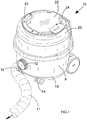
Figure 1 is a front three quarter perspective view of a drum and hose type vacuum cleaner according to the present invention. -
Figure 2 is a rear three quarter view of the vacuum cleaner. -
Figure 3 is a close-up view of a top region of the cleaner around a cable aperture. -
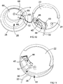
Figures 4 ,5 ,6 ,7 and 8 illustrate the steps involved in replacing an electric power cable. -
Figure 9 is a perspective view of the vacuum cleaner with power cable detached. -
Figure 10 is a perspective view of a disassembled cable reeler in accordance with the invention. -
Figure 11 is a perspective view of an assembled cable reeler. - In
Figure 1 a drum and hose type cleaner is shown generally as 10. The overall configuration and format corresponds to cleaners marketed under the Henry trade mark by Numatic International Ltd (applicant for the present application). - The cleaner comprises a
hose portion 11 attached at a base end to asuction port 12 of a drum shaped body 9. The cleaner has a generallycylindrical base portion 13. A front underside portion of the base portion is supported by twocastors wheels 16,17 (shown best infigure 2 ). The wheels share a common horizontal axle (not visible). The wheel and castor arrangement permits the body 9 to be towed behind thehose 11 by a user. - An upper
cylindrical lid portion 20 of the vacuum cleaner is disposed on an upper end region of the base portion. The lid portion is formed with an annular lowercircumferential shoulder feature 21 which is releasably clamped onto the base portion. The lid may be unclamped to allow access into an interior dust collection cavity (not visible) of the base portion. - An upper surface of a top end region of the
lid portion 20 is provided by a generally disc shapedreel flange piece 22. A folding carryhandle 23 is recessed into the flange piece so that it lies flush. A reelingbutton 24 stands proud of the surface and is rotatably mounted. A reel (shown infigure 11 ) is mounted transversely in the lid for rotation about a vertical axis of rotation, which is generally co-axial with the cylindrical form of the body 9. The reelupper flange 22 and a correspondinglower flange 28 are disposed either side of a spoolingdrum 25 shown infigure 10 . The drum is carried by an upstanding spigot axle (not shown). The reel is thus able to rotate and may be wound or unwound by a user manipulating thebutton 24. - A
cable aperture 30 is formed in asidewall 31 of the lid portion. The aperture is in the form of a horizontally elongate slot having curved ends. Anelectric power cable 32 feeds into the lid portion and runs onto the reel spooling drum inside the lid portion. Thus the cable may be spooled by winding thebutton 24 in the appropriate direction. The cable may be unspooled by the user tugging on the cable which draws the cable out as the reel turns in response. Alternatively the cable may unspool during use as the cleaner is wheeled over a floor surface. A distal end of the cable visible infigure 9 is provided with a three-pin UK mains plug 35 which may be plugged into a wall socket (not shown) - The present embodiment of the invention involves the provision of a plug and socket electrical connection in the reel assembly. This becomes visible in the series of
figures 3 to 8 . Infigure 1 anaccess panel 40 is a generally arcuate shaped flat member. The panel is formed of transparent plastics material. The panel is formed with mounting holes in which are disposed threaded mountingbolts figure 4 . The mounting bolts are self-tapping in theflange piece 22. The bolts may be removed by ascrewdriver 43. This allows the panel to be lifted as shown infigure 5 . Under the panel there is formed a recessedelectrical connection box 44. The box is provided with an International Electrotechnical Commission connection of a type specified in IEC 60320. This standard covers several connector configurations, and the particular connectors selected will be dictated by local standards, regulations and preferences. A machine end of theelectrical cable 32 is provided with anIEC socket connector 45. The socket connector is seated in aplug connector 46 visible infigure 8 . The cable extending from the engaged connector is threaded through a cut-out radial slot 60 (shown infigures 10 and 11 ) in the box floor. The slot communicates with the annularcable reel chamber 61 defined around thespool drum 25 between upper andlower flanges - A
sidewall fillet piece 47 is an elongate member formed at an upper region thereof with two axially oriented side-by-side collars tongue 50 which sits in a slot 51 (visible infigure 7 ). The slot extends down to an upper edge portion of thecable aperture 30. Thus the lower end of the tongue forms an upper portion of the aperture perimeter. On either side of the tongue are two downwardly facingwedge pieces bolts collars - The bolts may be unscrewed and the fillet vertically slid out of position. This allows the cable to be lifted out of the aperture via the
slot 51, as shown infigures 7 and 8 . The cable may be completely removed from the vacuum cleaner by unplugging of the IEC connectors. The cable may then be replaced as required and the fillet and panel replaced. - With the cable connector attached to the machine, the
connector 45 is engaged and the trailing cable placed in theflange slot 60. The cable is laid into thesidewall aperture 30 and the fillet slid into place and retained by the fixing bolts. When thebutton 24 is used to wind the reel the connection box andflange 22 rotate with the reel, drawing the cable in through the fixed aperture. Theflange slot 60 acts to snag the cable and draw it into the spoolingchamber 60 as the reel rotates. The button is rotated clockwise to load the reel and then allowed to unwind during use as the machine travels over a floor surface. - The electrical connection box makes an electrical connection with a drive motor via a conventional slip-ring arrangement (not shown) in the reeler mechanism. As shown in
figure 10 ,electrical wires connector socket 46 and toterminals 64,65 disposed on anannular collar 69 at a top region of thedrum spool 25. The terminals connect with contact bushes 66,67. When assembled theupper flange piece 22 located co-axially with the drum and lower flange and is fixed to the upper end face 68 of the drum spool, thereby to form the complete reel shown infigure 11 . - The present invention allows the easy disconnection and replacement of a power cable from a cable reeler mechanism in an electrical appliance. Prior art cable reels are typically attached directly to terminals associated with the spooling drum and slip rings used to take electrical power to an electric drive motor, such as a vacuum suction drive. Thus replacement of the cable involves complete disassembly of the machine and reeler mechanism. The present inventors have noted that the cable usually fails along its exposed unwound length, due to repeated bending, twisting and kinking. Thus the invention provides a detachable connector at a reel end of the cable which allows easy replacement of faulty exposed cable in the field. The internal terminal and slip ring connections in cable reelers rarely fail, so replacement of, and access to, these features is far less often required. Thus the appliances of the invention bypass the need to have access to these features for cable replacement.
- According to further and/or various aspects of the invention there are provided appliances as set forth in the statements of invention set out in the numbered paragraphs below:
- 1. A mobile mains-powered appliance (10), the appliance including a cable reeler (22,25,28) for a power supply cable (32), the reeler comprising a rotatable reel (25) onto which the cable can be wound, whereby the cable may be extended or retracted from the appliance by unwinding or winding of the cable from or onto the reel, wherein the cable is rendered detachable from the appliance by the provision of a detachable electric supply coupling comprising first and second coupling portions (45,46), the first portion (45) being attached to a machine end region of the cable, and the second portion (46) being attached to the appliance and disposed on or in an outside-facing cable reel flange portion (22) or an outside-facing flange portion attached to and axially spaced apart from the reel, so that the outside facing flange portion (22) and coupling (46) rotate with the reel during winding and unwinding, the coupling portions being adapted to be releasably engageable with one another so as to make or detach an electrical connection between the cable and the appliance.
- 2. An appliance according to paragraph 1 wherein the second portion (46) of the electric supply coupling is disposed on or in an external wall portion (22) of the appliance so that the coupling is accessible via the wall portion.
- 3. An appliance according to paragraph 1 or 2 wherein a cable path is provided which communicates between a region of the electric supply coupling which accommodates the coupling first portion via a slot (60) or cut-out which passes through the flange portion to a reel spooling space (61) for the cable.
- 4. An appliance according to any of paragraphs 1 to 3 wherein an electrical connection between the second coupling portion and an electric motor drive of the appliance is made via a slip ring type connection associated with the reeler.
- 5. An appliance according to any of paragraphs 1 to 4 wherein the second portion of the electric supply coupling is disposed under an openable access panel (40) so that the coupling is accessible to permit manual engagement or disengagement of the coupling portions when the access panel is opened.
- 6. An appliance according to paragraph 5 wherein the panel is held in place by at least one retaining element (41,42) which requires a separate tool to release for panel opening.
- 7. An appliance according to paragraph 5 or 6 wherein the access panel is formed of clear material, or provided with a window, so that the coupling may be inspected through the closed panel.
- 8. An appliance according to any of paragraphs 1 to 7 wherein the reel is enclosed in the appliance and a flange on or in which the second coupling portion is disposed forms an exterior wall portion (22) of the housing, which portion rotates with the reel.
- 9. An appliance according to paragraph 8 wherein the cable extends from the housing via a fixed aperture (30) in an exterior wall portion (31), which aperture opens into a circumferential spooling space in the appliance.
- 10. An appliance according to paragraph 9 wherein a detachable fillet (47) defines a perimeter portion of the aperture and extends to adjacent a rotatable flange which carries the second coupling portion, the arrangement being such that when the fillet is removed the cable may be placed in the aperture and the cable end carrying the first portion of the coupling may be led to the reel flange (22) for coupling.
- 11. An appliance according to
paragraph 10 wherein the fillet is provided with at least one retaining element (52,53) which requires a separate tool to release so as to permit removal of the fillet or to attach so as to fix the fillet in place. - 12. An appliance according to
paragraph - 13. An appliance according to any of paragraphs 1 to 12 which is a vacuum cleaner (10) and in which the mains supplies electrical power for an electric suction fan.
- 14. An appliance according to any of paragraphs 1 to 13 wherein the electrical coupling portions comprise a female socket and a male plug, such as specified by IEC 60320.
- 15. An appliance according to any of paragraphs 1 to 14 wherein the appliance is a canister type vacuum cleaner (10) having a body portion (9) and a wand portion which is connected to the drum portion by a flexible hose (11), the cable reeler being provided in an upper end region of the body portion drum, and arranged to as to rotate about a generally vertical axis.
Claims (12)
- A mobile mains-powered appliance (10), the appliance including a cable reeler (22,25,28) for a power supply cable (32), the reeler comprising a rotatable reel (25) onto which the cable can be wound, whereby the cable may be extended or retracted from the appliance by unwinding or winding of the cable from or onto the reel, wherein the cable is rendered detachable from the appliance by the provision of a detachable electric supply coupling comprising first and second coupling portions (45,46), the first portion (45) being attached to a machine end region of the cable, and the second portion (46) being disposed on or connected to the cable reel so that the coupling (46) rotates with the reel during winding and unwinding, the coupling portions being adapted to be releasably engageable with one another so as to make or detach an electrical connection between the cable and the appliance,
characterised in that the reel is enclosed in the appliance and a reel flange on or in which the second coupling portion is disposed forms an exterior wall portion (22) of the housing, which wall portion rotates with the reel, wherein the cable extends from the housing via a fixed aperture (30) in an exterior wall portion (31), which aperture opens into a circumferential spooling space in the appliance, and wherein a detachable fillet (47) defines a perimeter portion of the aperture and extends to adjacent the rotatable flange which carries the second coupling portion, the arrangement being such that when the fillet is removed the cable may be placed in the aperture and the cable end carrying the first portion of the coupling may be led to the reel flange (22) for coupling. - An appliance as claimed in claim 1 wherein the second portion (46) of the electric supply coupling is disposed on or in an external wall portion (22) of the appliance so that the coupling is accessible via the wall portion.
- An appliance as claimed in claim 1 or claim 2 wherein a cable path is provided which communicates between a region of the electric supply coupling which accommodates the coupling first portion via a slot (60) or cut-out which passes through the flange portion to a reel spooling space (61) for the cable.
- An appliance as claimed in any preceding claim wherein an electrical connection between the second coupling portion and an electric motor drive of the appliance is made via a slip ring type connection associated with the reeler.
- An appliance as claimed in any preceding claim wherein the second portion of the electric supply coupling is disposed under an openable access panel (40) so that the coupling is accessible to permit manual engagement or disengagement of the coupling portions when the access panel is opened.
- An appliance as claimed in claim 5 wherein the panel is held in place by at least one retaining element (41,42) which requires a separate tool to release for panel opening.
- An appliance as claimed in claim 5 or claim 6 wherein the access panel is formed of clear material, or provided with a window, so that the coupling may be inspected through the closed panel.
- An appliance as claimed in any preceding claim wherein the fillet is provided with at least one retaining element (52,53) which requires a separate tool to release so as to permit removal of the fillet or to attach so as to fix the fillet in place.
- An appliance as claimed in any preceding claim wherein the coupling is recessed (44) from an exterior wall of the appliance and a cable snag or clamp is provided in the recess which prevents decoupling under reeling loading of the cable.
- An appliance as claimed in any preceding claim which is a vacuum cleaner (10) and in which the mains supplies electrical power for an electric suction fan.
- An appliance as claimed in any preceding claim wherein the electrical coupling portions comprise a female socket and a male plug, such as specified by IEC 60320.
- An appliance according to any of the preceding claims wherein the appliance is a canister type vacuum cleaner (10) having a body portion (9) and a wand portion which is connected to the drum portion by a flexible hose (11), the cable reeler being provided in an upper end region of the body portion drum, and arranged to as to rotate about a generally vertical axis.
Applications Claiming Priority (2)
| Application Number | Priority Date | Filing Date | Title |
|---|---|---|---|
| GBGB0910679.0A GB0910679D0 (en) | 2009-06-19 | 2009-06-19 | Mobile electrical appliance with cable reeler |
| EP10731779.4A EP2443714B1 (en) | 2009-06-19 | 2010-06-17 | Mobile electrical appliance with cable reeler |
Related Parent Applications (2)
| Application Number | Title | Priority Date | Filing Date |
|---|---|---|---|
| EP10731779.4A Division EP2443714B1 (en) | 2009-06-19 | 2010-06-17 | Mobile electrical appliance with cable reeler |
| EP10731779.4A Division-Into EP2443714B1 (en) | 2009-06-19 | 2010-06-17 | Mobile electrical appliance with cable reeler |
Publications (1)
| Publication Number | Publication Date |
|---|---|
| EP3287060A1 true EP3287060A1 (en) | 2018-02-28 |
Family
ID=40972511
Family Applications (2)
| Application Number | Title | Priority Date | Filing Date |
|---|---|---|---|
| EP10731779.4A Active EP2443714B1 (en) | 2009-06-19 | 2010-06-17 | Mobile electrical appliance with cable reeler |
| EP17195199.9A Withdrawn EP3287060A1 (en) | 2009-06-19 | 2010-06-17 | Mobile electrical appliance with cable reeler |
Family Applications Before (1)
| Application Number | Title | Priority Date | Filing Date |
|---|---|---|---|
| EP10731779.4A Active EP2443714B1 (en) | 2009-06-19 | 2010-06-17 | Mobile electrical appliance with cable reeler |
Country Status (6)
| Country | Link |
|---|---|
| US (1) | US20120137466A1 (en) |
| EP (2) | EP2443714B1 (en) |
| CN (1) | CN102804534A (en) |
| CA (1) | CA2765918A1 (en) |
| GB (1) | GB0910679D0 (en) |
| WO (1) | WO2010146363A2 (en) |
Cited By (1)
| Publication number | Priority date | Publication date | Assignee | Title |
|---|---|---|---|---|
| DE102019124947A1 (en) * | 2019-09-17 | 2021-03-18 | Sprintus Gmbh | Wired cleaning device |
Families Citing this family (9)
| Publication number | Priority date | Publication date | Assignee | Title |
|---|---|---|---|---|
| IL213522A (en) | 2011-06-13 | 2016-07-31 | Kramer Electronics Ltd | Rewindable electrical cable extension device |
| CN103961025A (en) * | 2013-02-04 | 2014-08-06 | 苏州宝时得电动工具有限公司 | Dust collector |
| WO2015143110A1 (en) * | 2014-03-19 | 2015-09-24 | Lam Qui Moc | Power management devices and kits including the same |
| CN104097994A (en) * | 2014-07-22 | 2014-10-15 | 珠海格力电器股份有限公司 | Winder and electrical equipment with same |
| DE102017131462A1 (en) * | 2017-06-08 | 2018-12-13 | Festool Gmbh | Electrical device as a system component for controlling a vacuum cleaner |
| US10687678B2 (en) | 2017-06-12 | 2020-06-23 | Emerson Electric Co. | Power systems and methods including a battery charger and safety switch |
| US10709305B2 (en) | 2017-06-12 | 2020-07-14 | Emerson Electric Co. | Vacuum cleaning system including an electrical connection interface |
| EP3488751B1 (en) * | 2017-11-22 | 2023-06-07 | Guido Valentini | Vacuum cleaner |
| CN113745903B (en) * | 2021-09-15 | 2023-05-30 | 广东电网有限责任公司 | Power cable collecting and storing device |
Citations (5)
| Publication number | Priority date | Publication date | Assignee | Title |
|---|---|---|---|---|
| US3346705A (en) * | 1964-02-28 | 1967-10-10 | Robert E Breidenthal | Electric cord reel apparatus |
| US4467979A (en) * | 1982-02-01 | 1984-08-28 | Noma Inc. | Cord reel |
| US5023410A (en) * | 1990-01-02 | 1991-06-11 | Whirlpool Corporation | Cord reel contacts for a vacuum cleaner |
| JPH09201318A (en) * | 1996-01-30 | 1997-08-05 | Sanyo Electric Co Ltd | Vacuum cleaner |
| EP1367016A2 (en) * | 2002-05-21 | 2003-12-03 | Electrolux Outdoor Products Limited | Cable storage device |
Family Cites Families (41)
| Publication number | Priority date | Publication date | Assignee | Title |
|---|---|---|---|---|
| US1714225A (en) * | 1925-02-25 | 1929-05-21 | Carl L Hyde | Conductor-retrieving device for vacuum cleaners |
| US2013733A (en) * | 1934-11-06 | 1935-09-10 | Claude M Murphy | Winding reel for cables |
| US2270997A (en) * | 1939-11-16 | 1942-01-27 | Joseph Fisher | Iron cord holder |
| US2322038A (en) * | 1940-12-12 | 1943-06-15 | Electrolux Corp | Cord-winding device |
| US2323275A (en) * | 1941-01-16 | 1943-06-29 | Electrolux Corp | Cord-winding device |
| US2450257A (en) * | 1944-04-20 | 1948-09-28 | Joy Mfg Co | Reel mechanism |
| US2801303A (en) * | 1953-01-19 | 1957-07-30 | Grace N Pailing | Cord reel |
| US2825087A (en) * | 1954-05-14 | 1958-03-04 | Lewyt Corp | Support for vacuum cleaner accessories |
| US2948913A (en) * | 1954-07-20 | 1960-08-16 | Bernard J Tamarin | Vacuum cleaner construction |
| US2839775A (en) * | 1954-09-14 | 1958-06-24 | Whirlpool Co | Vacuum cleaner cord reel mounting |
| US2937395A (en) * | 1955-02-01 | 1960-05-24 | Lewyt Corp | Vacuum cleaner assembly |
| US2937396A (en) * | 1957-01-15 | 1960-05-24 | Singer Mfg Co | Vacuum cleaners with cord reels |
| US3110453A (en) * | 1962-01-02 | 1963-11-12 | Aero Motive Mfg Company | Cable release |
| US3447189A (en) * | 1965-11-12 | 1969-06-03 | Gen Electric | Vacuum cleaner with cord reel |
| US3374319A (en) * | 1966-04-25 | 1968-03-19 | Stahmer Bernhardt | Cable take-up reel |
| US3456280A (en) * | 1967-10-24 | 1969-07-22 | Electrolux Corp | Vacuum cleaner with cordwinder,wire harness,and electrical terminal board |
| US3826879A (en) * | 1972-12-20 | 1974-07-30 | Nat Union Electric Corp | Retractable electric cord reel |
| US3835267A (en) * | 1973-12-04 | 1974-09-10 | F Sharpe | Reel for electric extension cords |
| US3929210A (en) * | 1974-05-28 | 1975-12-30 | Vacuum Cleaner Corp Of America | Retractable cord reel |
| US3983977A (en) * | 1975-11-19 | 1976-10-05 | Crabb Virgil R | Electric extension cord reel |
| NL7602589A (en) * | 1976-03-12 | 1977-09-14 | Draka Kabel Bv | CORD REEL. |
| US4061290A (en) * | 1976-05-13 | 1977-12-06 | Harrill Thomas D | Extension cord reel and case |
| US4114736A (en) | 1977-07-05 | 1978-09-19 | Volker Scherenberg | Cord retractor for retracting cord of electrical appliances |
| US4136840A (en) * | 1978-01-23 | 1979-01-30 | Bates Charles A | Cord take-up reel for an electric lawn mower |
| JPS5824132B2 (en) * | 1978-04-28 | 1983-05-19 | 松下電器産業株式会社 | Vacuum cleaner cord winding device |
| US4338497A (en) * | 1980-05-07 | 1982-07-06 | Noma Canada Ltd. | Extension cord reel set |
| JPS60161868A (en) * | 1984-02-02 | 1985-08-23 | Matsushita Electric Ind Co Ltd | cord reel |
| US4705484A (en) * | 1986-10-09 | 1987-11-10 | Mega/Erg Inc. | Power cord, wire and cable container |
| US4913369A (en) * | 1989-06-02 | 1990-04-03 | Welch Allyn, Inc. | Reel for borescope insertion tube |
| US4940859A (en) * | 1989-07-24 | 1990-07-10 | Daniel Peterson | Telephone cord take-up reel assembly |
| US5183982A (en) * | 1990-09-26 | 1993-02-02 | Gmi Holdings, Inc. | Manually adjustable housing portions for actuating an electrical appliance switch |
| DE4406583A1 (en) * | 1994-03-01 | 1994-07-28 | Frank Dipl Ing Arbeiter | Reeling device for cable fixed to transportable electrical equipment |
| DE4413247C2 (en) * | 1994-04-16 | 1996-02-15 | Cielker Werner | Device for storing and dispensing a flexible rod |
| SE505396C2 (en) * | 1995-11-09 | 1997-08-18 | Electrolux Ab | Towing device for a cable reel with a cable drum rotating on a stationary shaft |
| DE10131694B4 (en) * | 2001-06-29 | 2004-07-29 | BSH Bosch und Siemens Hausgeräte GmbH | Kabelausziehöffnung |
| CA2435015A1 (en) * | 2003-07-11 | 2005-01-11 | Keith Thiessen | Storage device for coiled articles |
| US6848937B1 (en) * | 2003-09-09 | 2005-02-01 | Feng-Shen Hsiao | Retractable extension cord housing having a low-profile plug holder |
| KR20080105847A (en) * | 2007-06-01 | 2008-12-04 | 엘지전자 주식회사 | Vacuum cleaner |
| US7915528B2 (en) * | 2008-05-15 | 2011-03-29 | Wenzhou Mtlc Electric Appliances Co., Ltd. | Face slide weatherproof electric enclosure |
| CN101841109A (en) * | 2009-03-16 | 2010-09-22 | 张大庆 | Active protective cable reel safety socket |
| KR20100137079A (en) * | 2009-06-22 | 2010-12-30 | 삼성광주전자 주식회사 | Vacuum cleaner with removable cord reel unit |
-
2009
- 2009-06-19 GB GBGB0910679.0A patent/GB0910679D0/en not_active Ceased
-
2010
- 2010-06-17 EP EP10731779.4A patent/EP2443714B1/en active Active
- 2010-06-17 CA CA2765918A patent/CA2765918A1/en not_active Abandoned
- 2010-06-17 CN CN2010800273028A patent/CN102804534A/en active Pending
- 2010-06-17 WO PCT/GB2010/001189 patent/WO2010146363A2/en not_active Ceased
- 2010-06-17 EP EP17195199.9A patent/EP3287060A1/en not_active Withdrawn
-
2011
- 2011-12-19 US US13/330,033 patent/US20120137466A1/en not_active Abandoned
Patent Citations (5)
| Publication number | Priority date | Publication date | Assignee | Title |
|---|---|---|---|---|
| US3346705A (en) * | 1964-02-28 | 1967-10-10 | Robert E Breidenthal | Electric cord reel apparatus |
| US4467979A (en) * | 1982-02-01 | 1984-08-28 | Noma Inc. | Cord reel |
| US5023410A (en) * | 1990-01-02 | 1991-06-11 | Whirlpool Corporation | Cord reel contacts for a vacuum cleaner |
| JPH09201318A (en) * | 1996-01-30 | 1997-08-05 | Sanyo Electric Co Ltd | Vacuum cleaner |
| EP1367016A2 (en) * | 2002-05-21 | 2003-12-03 | Electrolux Outdoor Products Limited | Cable storage device |
Cited By (2)
| Publication number | Priority date | Publication date | Assignee | Title |
|---|---|---|---|---|
| DE102019124947A1 (en) * | 2019-09-17 | 2021-03-18 | Sprintus Gmbh | Wired cleaning device |
| EP3800747A1 (en) * | 2019-09-17 | 2021-04-07 | Sprintus GmbH | Wired cleaning device |
Also Published As
| Publication number | Publication date |
|---|---|
| US20120137466A1 (en) | 2012-06-07 |
| EP2443714A2 (en) | 2012-04-25 |
| WO2010146363A2 (en) | 2010-12-23 |
| EP2443714B1 (en) | 2017-11-22 |
| GB0910679D0 (en) | 2009-08-05 |
| WO2010146363A3 (en) | 2011-11-17 |
| CA2765918A1 (en) | 2010-12-23 |
| CN102804534A (en) | 2012-11-28 |
Similar Documents
| Publication | Publication Date | Title |
|---|---|---|
| EP2443714B1 (en) | Mobile electrical appliance with cable reeler | |
| US9172232B2 (en) | Charging cable housing apparatus | |
| US20090057085A1 (en) | Reel and reel housing | |
| US7316368B2 (en) | Direct current powered hose rewinding apparatus | |
| US20140311849A1 (en) | Cable housing apparatus | |
| US20070194163A1 (en) | Reel with housing having triangular aperture for entry of linear material | |
| US7490706B2 (en) | Retractable electric cord receiving device and ventilation apparatus | |
| US9661834B2 (en) | Dual-bearing reel | |
| TWI900772B (en) | Reel assembly for a housing | |
| US20120138167A1 (en) | Air hose/electric cord reel | |
| EP1367016B1 (en) | Lawnmower with a cable storage device | |
| US20080282496A1 (en) | Vacuum hose reel | |
| US20030038203A1 (en) | Retractable block heater cord assembly | |
| JPH10337680A (en) | Tool box with cord reel | |
| CN113612090B (en) | Cable winding and unwinding device | |
| CN101222872A (en) | Winding device for cables of electrical equipment | |
| CN221235013U (en) | Multifunctional line concentration box | |
| CN221242703U (en) | Reel assembly for dust collector | |
| KR101680654B1 (en) | Air hose reel device | |
| CN212517650U (en) | An oil-resistant and corrosion-resistant cable | |
| JPH10340770A (en) | Winding-type cord set | |
| CA2515171C (en) | Direct current powered hose rewinding apparatus | |
| JP2001130838A (en) | Cable reel | |
| JPH07124090A (en) | Vacuum cleaner | |
| JP2023056808A (en) | cord reel |
Legal Events
| Date | Code | Title | Description |
|---|---|---|---|
| PUAI | Public reference made under article 153(3) epc to a published international application that has entered the european phase |
Free format text: ORIGINAL CODE: 0009012 |
|
| STAA | Information on the status of an ep patent application or granted ep patent |
Free format text: STATUS: THE APPLICATION HAS BEEN PUBLISHED |
|
| AC | Divisional application: reference to earlier application |
Ref document number: 2443714 Country of ref document: EP Kind code of ref document: P |
|
| AK | Designated contracting states |
Kind code of ref document: A1 Designated state(s): AL AT BE BG CH CY CZ DE DK EE ES FI FR GB GR HR HU IE IS IT LI LT LU LV MC MK MT NL NO PL PT RO SE SI SK SM TR |
|
| STAA | Information on the status of an ep patent application or granted ep patent |
Free format text: STATUS: REQUEST FOR EXAMINATION WAS MADE |
|
| 17P | Request for examination filed |
Effective date: 20180820 |
|
| RBV | Designated contracting states (corrected) |
Designated state(s): AL AT BE BG CH CY CZ DE DK EE ES FI FR GB GR HR HU IE IS IT LI LT LU LV MC MK MT NL NO PL PT RO SE SI SK SM TR |
|
| STAA | Information on the status of an ep patent application or granted ep patent |
Free format text: STATUS: EXAMINATION IS IN PROGRESS |
|
| 17Q | First examination report despatched |
Effective date: 20200309 |
|
| STAA | Information on the status of an ep patent application or granted ep patent |
Free format text: STATUS: THE APPLICATION IS DEEMED TO BE WITHDRAWN |
|
| 18D | Application deemed to be withdrawn |
Effective date: 20220405 |