EP3800397B1 - Vergasungs- und/oder verbrennungssystem zur ausstattung einer vergasungs- und/oder verbrennungsanlage - Google Patents
Vergasungs- und/oder verbrennungssystem zur ausstattung einer vergasungs- und/oder verbrennungsanlage Download PDFInfo
- Publication number
- EP3800397B1 EP3800397B1 EP20194663.9A EP20194663A EP3800397B1 EP 3800397 B1 EP3800397 B1 EP 3800397B1 EP 20194663 A EP20194663 A EP 20194663A EP 3800397 B1 EP3800397 B1 EP 3800397B1
- Authority
- EP
- European Patent Office
- Prior art keywords
- gasification
- reactor
- combustion
- plate
- installation
- Prior art date
- Legal status (The legal status is an assumption and is not a legal conclusion. Google has not performed a legal analysis and makes no representation as to the accuracy of the status listed.)
- Active
Links
Images

Classifications
-
- F—MECHANICAL ENGINEERING; LIGHTING; HEATING; WEAPONS; BLASTING
- F23—COMBUSTION APPARATUS; COMBUSTION PROCESSES
- F23B—METHODS OR APPARATUS FOR COMBUSTION USING ONLY SOLID FUEL
- F23B30/00—Combustion apparatus with driven means for agitating the burning fuel; Combustion apparatus with driven means for advancing the burning fuel through the combustion chamber
- F23B30/02—Combustion apparatus with driven means for agitating the burning fuel; Combustion apparatus with driven means for advancing the burning fuel through the combustion chamber with movable, e.g. vibratable, fuel-supporting surfaces; with fuel-supporting surfaces that have movable parts
-
- F—MECHANICAL ENGINEERING; LIGHTING; HEATING; WEAPONS; BLASTING
- F23—COMBUSTION APPARATUS; COMBUSTION PROCESSES
- F23B—METHODS OR APPARATUS FOR COMBUSTION USING ONLY SOLID FUEL
- F23B40/00—Combustion apparatus with driven means for feeding fuel into the combustion chamber
- F23B40/04—Combustion apparatus with driven means for feeding fuel into the combustion chamber the fuel being fed from below through an opening in the fuel-supporting surface
-
- F—MECHANICAL ENGINEERING; LIGHTING; HEATING; WEAPONS; BLASTING
- F23—COMBUSTION APPARATUS; COMBUSTION PROCESSES
- F23G—CREMATION FURNACES; CONSUMING WASTE PRODUCTS BY COMBUSTION
- F23G5/00—Incineration of waste; Incinerator constructions; Details, accessories or control therefor
- F23G5/24—Incineration of waste; Incinerator constructions; Details, accessories or control therefor having a vertical, substantially cylindrical, combustion chamber
- F23G5/26—Incineration of waste; Incinerator constructions; Details, accessories or control therefor having a vertical, substantially cylindrical, combustion chamber having rotating bottom
-
- F—MECHANICAL ENGINEERING; LIGHTING; HEATING; WEAPONS; BLASTING
- F23—COMBUSTION APPARATUS; COMBUSTION PROCESSES
- F23G—CREMATION FURNACES; CONSUMING WASTE PRODUCTS BY COMBUSTION
- F23G7/00—Incinerators or other apparatus for consuming industrial waste, e.g. chemicals
- F23G7/10—Incinerators or other apparatus for consuming industrial waste, e.g. chemicals of field or garden waste or biomasses
-
- F—MECHANICAL ENGINEERING; LIGHTING; HEATING; WEAPONS; BLASTING
- F23—COMBUSTION APPARATUS; COMBUSTION PROCESSES
- F23G—CREMATION FURNACES; CONSUMING WASTE PRODUCTS BY COMBUSTION
- F23G2203/00—Furnace arrangements
- F23G2203/80—Furnaces with other means for moving the waste through the combustion zone
- F23G2203/805—Furnaces with other means for moving the waste through the combustion zone using a rotating hearth
-
- F—MECHANICAL ENGINEERING; LIGHTING; HEATING; WEAPONS; BLASTING
- F23—COMBUSTION APPARATUS; COMBUSTION PROCESSES
- F23G—CREMATION FURNACES; CONSUMING WASTE PRODUCTS BY COMBUSTION
- F23G2209/00—Specific waste
- F23G2209/26—Biowaste
Definitions
- the present invention relates to a solid fuel gasification and/or combustion system intended to equip a gasification and/or combustion installation.
- the present invention also relates to a gasification and/or combustion installation provided with such a gasification and/or combustion system.
- the present invention also relates to a method of implementing such a gasification and/or combustion installation.
- a gasification and/or combustion installation comprises a hearth inside which a bed of a solid fuel, in particular from biomass, is burned to provide heat. Such an installation also generates mineral residues, such as ashes or the like.
- a general problem posed in this area lies in the continuous evacuation of mineral residues produced during the combustion and/or gasification of solid fuel. Indeed, it is desirable to avoid regular shutdowns of the gasification and/or combustion installation to occasionally evacuate mineral residues. Also, it is known to equip the gasification and/or combustion installation with an ash removal grid which is designed to evacuate mineral residues from the hearth.
- US 4,388,876 A shows a combustion system with a supply pipe in the center of a rotating grate. The two-part form of claim 1 is based on US 4,388,876 A .
- the gasification and/or combustion installation must allow the solid fuel to be set in motion to continuously supply said installation as the fuel is burned and/or gasified.
- the gasification and/or combustion installation must also allow the evacuation of mineral residues as they are produced, such evacuation must be carried out at a controlled speed. Indeed, a speed of evacuation of mineral residues that is too rapid risks inducing evacuation of unburned solid fuels, which negatively affects the efficiency of the gasification and/or combustion installation. Conversely, a speed of evacuation of mineral residues that is too slow risks inducing the formation of clinker which is likely to damage said installation.
- the gasification and/or combustion installation must in all circumstances avoid the production of clinker which results from a melting of mineral residues when a hearth temperature is higher than a melting temperature of the mineral residues.
- the gasification and/or combustion installation must be provided with an air injection device to supply the hearth with an appropriate quantity of air which is notably necessary for the complete combustion of a tank, coming from a incomplete combustion of solid fuel.
- air injection must also be carried out appropriately to guarantee a rise in temperature of the solid fuel allowing drying, pyrolysis and combustion of the solid fuel.
- the gasification and/or combustion installation must allow control of the height of solid fuel inside the hearth.
- the height of solid fuel inside the hearth affects the combustion and/or gasification conditions and is likely to cause malfunctions in said installation.
- a height of solid fuel is too great, due to a change in fuel characteristics or a variation in operating conditions, this results in an increase in pressure loss within the solid fuel bed. , which is detrimental.
- An excessive height of solid fuel inside the hearth is likely to affect the injection of air into the hearth, or even to block such injection, and ultimately to cause said installation to stop.
- the gasification and/or combustion installation must be compatible with a variety of solid fuels. Indeed, it is desirable to be able to consume and/or gasify solid fuels having variable properties, such as a humidity level, a calorific value, an ash level or the like, inside the hearth. This results in a need to equip the gasification and/or combustion installation with a regulation system allowing the transition from a solid fuel to another solid fuel, without having to shut down said installation.
- the gasification and/or combustion installation must be airtight, particularly at its hearth, to avoid in particular the entry of parasitic air, gas leaks and/or thermal losses.
- An aim of the present invention is to propose a system for the gasification and/or combustion of a solid fuel intended to equip an installation for the gasification and/or combustion of a solid fuel, in particular from biomass, which meets the requirements of all of the above objectives.
- Another aim of the present invention is to propose an installation for gasification and/or combustion of solid fuel which meets all of the above-mentioned objectives.
- Another aim of the present invention is to propose a method of implementing such an installation which offers a better compromise between the aforementioned objectives.
- the present invention improves the situation, by proposing a system for gasification and/or combustion of a solid fuel intended to equip a reactor with an installation for gasification and/or combustion of a solid fuel, in particular from biomass, which comprises an ash removal grid overhung by a cone for supplying solid fuel to the reactor from below, the ash removal grid being automated, cooled and actuated by a piston, the gasification system and/or combustion offering the best compromise between the aforementioned objectives. More particularly, such a system allows a thermal combustion reaction of good quality while limiting the formation of bottom ash, in particular by allowing evacuation of mineral residues, ashes in particular, continuously, the gasification and/or combustion system making it possible to burn successively distinct solid fuels, without stopping said installation.
- the present invention also relates to a gasification and/or combustion installation comprising such a gasification and/or combustion system, the gasification and/or combustion installation comprising a reactor delimited by at least one wall which houses the gasification and/or combustion system,
- the present invention also relates to a method of implementing such a gasification and/or combustion installation, the method comprising a step of drying the solid fuel during its admission inside the reactor via of the orifice equipped with a outlet of the supply channel, a step of spreading the solid fuel along the conical external surface of the supply cone from the top of the supply cone towards a base of the supply cone, a step of cooling the fuel solid partially consumed at the level of the lower portion of the reactor wall, a step of consuming solid unburned residues via the primary air injected at the level of the lower portion of the reactor wall, a first step of evacuation of mineral residues from the ash grate towards the hydraulic guard and a second step of evacuation of mineral residues continuously via the conveying system from the hydraulic guard towards the external environment of the reactor.
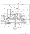
- a gasification and/or combustion installation 1 of the present invention is shown in section inside an orthonormal reference Oxyz linked to said installation 1.
- the orthonormal reference Oxyz defines a longitudinal direction Ox, a vertical direction Oy, parallel to Earth's gravity, and a transverse direction Oz.
- the orthonormal coordinate system Oxyz also defines a horizontal plane Oxz, a longitudinal plane Oxy and a transverse plane Oyz.
- the gasification and/or combustion installation 1 is intended to burn and/or gasify a solid fuel 2, in particular from biomass, with a view to producing heat Q.
- the gasification and/or combustion installation 1 comprises a reactor 4 which is arranged around an axis of symmetry A1 parallel to the direction Oy.
- the reactor 4 comprises a wall 5, in particular cylindrical, which delimits an upper enclosure 3 to the interior of which the solid fuel 2 is admitted.
- the gasification and/or combustion installation 1 is equipped with a gasification and/or combustion system 50 which is housed inside the reactor 4 of the gasification and/or combustion installation 1.
- the gasification and/or combustion system 50 comprises a supply cone 6 of solid fuel 2 from the reactor 4 which is arranged around a first axis of revolution A2 coincident with the axis of symmetry A1.
- the supply cone 6 has a conical external surface 7 and a top 8 which is provided with an orifice 9 for supplying solid fuel 2 to the reactor 4.
- the orifice 9 extends inside a plane orifice P1 which is orthogonal to the axis of symmetry A1.
- the conical outer surface 7 extends from the apex 8 to a base 10 of the supply cone 6, which extends within a base plane P2.
- the orifice plane P1 and the base plane P2 are parallel to each other and parallel to the plane Oxz.
- the conical external surface 7 and the axis of symmetry A1 form between them an angle ⁇ which is between 5° and 70°, preferably of the order of 20°, to within +/- 10%.
- the supply cone 6 is for example made of a metallic material resistant to high temperatures, notably stainless steel or the like.
- the supply cone 6 can be cooled via a water circuit and/or an air circuit 11.
- the orifice 9 corresponds to an outlet 12 of a supply channel 13 of solid fuel 2.
- the supply channel 13 is preferably arranged in a cylindrical tube arranged around a second axis of revolution A3 merging with the axis of symmetry A1.
- the supply channel 13 houses a solid fuel supply device 14 2 which indifferently comprises at least one piston, a belt conveyor, a chain conveyor, a screw, such as an Archimedes screw, or the like, to convey the solid fuel 2 from a reserve 15 of solid fuel 2 to the orifice 9 of the supply cone 6.
- the gasification and/or combustion system 50 comprises an ash removal grid 17 which comprises at least two plates 18, 19, including a first plate 18, preferably upper, and a second plate 19, preferably lower.
- the supply cone 6 overhangs the ash grate 17.
- the first plate 18 is interposed between the second plate 19 and the supply cone 6.
- the first plate 18 extends inside a first plane P3 and the second plate 19 extends inside a second plane P4, the first plane P3 and the second plane P4 being parallel to the orifice plane P1 and to the base plane P2.
- the first plate 18 and the second plate 19 are movable relative to each other via a rotary movement of one and/or the other around an axis of rotation A4, preferably confused with the axis of symmetry A1.
- the first plate 18 has a first radius R1 which is less than a second radius R2 of the second plate 19, the radii R1, R2 being measured between a respective radial end of the first plate 18 and the second plate 19, and the axis rotation A4.
- the rotary movement of the first plate 18 and/or the second plate 19 is for example provided by a jack 20.
- the rotary movement is an oscillatory movement of the second plate 19 relative to the first plate 18 which is fixed, the oscillatory movement of the second plate 19 taking place inside the second plan P4.
- the oscillatory movement comprises a succession of rotational movements of alternating directions and of amplitude less than 90°. Such an oscillatory movement contributes to the spreading of the mound 16 of solid fuel 2 on the ash removal grid 17.
- the number of plates 18, 19 is likely to be greater than two.
- the second plate 19 is mobile and is overlooked by a plurality of first plates 18. These first plates 18 are either fixed or mobile.
- the second plate 19 is fixed and is overlooked by a plurality of first plates 18. At least one of the first plates 18 is mobile, the other first plates 18 being either fixed or mobile. In these two cases, we understand that a plateau preferably has a lower radius than the plateaus it overhangs.
- the reactor 4 comprises a primary air injection system 21 which is capable of delivering primary air 22 into two delivery zones Z1, Z2.
- a first delivery zone Z1 is located at the level of the ash grate 17, and more particularly inside an interstitial space 23 provided between the first plate 18 and the second plate 19.
- a second delivery zone Z2 is located at the level of a lower portion 24 of the wall 5 of the reactor 4.
- the reactor 4 is provided with a cooling system 26 for its wall 5.
- the cooling system 26 comprises for example at least one circulation channel 27 for a fluid, such as water or the like.
- the circulation channel 27 is for example arranged in an annular channel provided at the level of the lower portion 24 of the wall 5 of the reactor 4.
- the circulation channel 27 extends inside a channel plane P5 which is parallel to the first plane P3 and to the second plane P4.
- the channel plane P5 is preferably interposed between the orifice plane P1 and the base plane P2.
- the circulation channel 27 overlaps the ash grate 17 and is currently in contact with the mound 16 of solid fuel 2.
- the channel plane P5 thus defines a limit between a drying zone 101 and a pyrolysis / gasification zone 102 which are located above the channel plane P5 and a combustion zone of unburned products 103 which is located below the channel plane P5 and preferably at the periphery of the ash grate 17.
- the cooling system 26 contributes to avoiding the formation of bottom ash inside the reactor 4 from a lowering of a first temperature T1 of the upper enclosure 3, in particular at the level of the lower portion 24 of the wall 5.
- drying zone 101 is located mainly above the orifice 9, that the pyrolysis / gasification zone 102 is mainly located at level of the conical external surface 7 of the supply cone 6 and that the combustion zone of unburned products 103 surrounds the periphery of the ash grate 17.
- the reactor 4 is equipped with a regulation system 28 comprising a differential pressure sensor 29 making it possible to regulate a height H of the mound 16 of solid fuel 2, the height H of the mound 16 being taken parallel to the axis of symmetry A1 between the base 10 of the supply cone 6 and a top 30 of the mound 16.
- the differential pressure sensor 29 is capable of measuring a pressure difference between a first pressure P'1 prevailing in the upper enclosure 3 of the reactor 4 and a second pressure P'2 prevailing in a chamber 31 located under the ash grate 17.
- the reactor 4 also includes a hydraulic guard 32, provided under the ash grate 17, and more particularly under the chamber 31, which is intended to ensure sealing of the gasification and/or combustion installation 1.
- the hydraulic guard 32 is also intended to protect said installation 1 in the event of a gas explosion and the hydraulic guard 32 also ensures cooling and humidification of mineral residues 25, prior to their evacuation from the reactor 4.
- the hydraulic guard 32 includes a basin 33 filled with a liquid 34, water in particular.
- the basin 33 comprises uprights 35 which rise up to the wall 5 of the reactor 4 to isolate the reactor 4 from an environment external 36 to said installation 1. This results in maintaining a depression of the upper enclosure 3 by relationship to the external environment 36.
- the hydraulic guard 32 is equipped with a conveying system 37 which is capable of recovering the mineral residues 25 falling by gravity inside the hydraulic guard 32 and of conveying these mineral residues 25 outside the reactor 4.
- the system conveying device 37 comprises for this purpose at least one conveying device 38, such as a treadmill, a chain conveyor, a screw or the like which extends from the hydraulic guard 32 to the environment external 36 to the reactor 4.
- the reactor 4 is equipped with an automatic control system 39 of parameters allowing continued operation of said installation 1, namely a second temperature T2 of the ash grate 17, a third temperature T3 of the air contained in the interior of the upper enclosure 3 and the differential pressure measuring the pressure difference between the first pressure P'1 and the second pressure P'2.
- the automatic control system 39 is able to control the operations of a fan 40 for extracting air from the upper enclosure 3, of the primary air injection system 21 to the inside the reactor 4, the actuator 20 for oscillating the first plate 18 and/or the second plate 19 and the device 14 for supplying solid fuel 2 to the reactor 4.
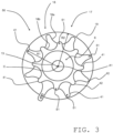
- the first plates 18 are two in number and we distinguish, among the first plates 18, a first upper plate 18b which overlooks a first lower plate 18a.
- the second plate 19 is a circular plate arranged around the axis of symmetry A1 while the first plates 18a, 18b are each shaped like a star comprising a plurality of radial branches 41 which extend from a center C of the first plate 18a , 18b to a periphery 42 of each of the first plates 18a, 18b.
- the second plate 19 rotates by an angle
- the first lower plate 18a rotates by half this angle and the first upper plate 18b is fixed.
- each first plate 18a, 18b has eight radial branches 41, this number being likely to be different and to vary from a first plate 18a, 18b to another first plate 18a, 18b.
- Each radial branch 41 has an end 51 which is preferably rounded. Note that the radial branches 41 are capable of being of any conformation and can in particular be sliced, shortened, cut, beveled and different from each other. Note that the supply channel 13 crosses the first plates 18a, 18b and the second plate 19 at their respective centers.
- the aforementioned gasification and/or combustion installation 1 allows implementation of a combustion and/or gasification process for the solid fuel 2, which comprises the following successive stages.
- Said method comprises a step of drying the solid fuel 2 during its admission inside the reactor 4 via the outlet 12 of the supply channel 13.
- the drying zone 101 is located vertically and near of the orifice 9 of the supply cone 6, a temperature of the drying zone 101 being notably between 850°C and 950°C.
- Said method then comprises a step of spreading the solid fuel 2 along the conical external surface 7 of the supply cone 6 from the top 8 of the supply cone 6 towards the base 10 of the supply cone 6.
- Such spreading stage commonly lasts between 10 min to 20 min, which allows the solid fuel 2 to be gasified in a reducing atmosphere, poor in oxygen.
- the solid fuel 2 is at least partially consumed.
- Said method then comprises a step of cooling the solid fuel 2 partially consumed at the level of the lower portion 24 of the wall 5 of the reactor 4.
- the mineral residues 25 resulting from the gasification are cooled by the cooling system 26, which avoids mineral residues 25 to be brought to a temperature higher than their melting temperature.
- Said process then comprises a step of consuming the solid unburned residues via the primary air 22 injected at the bottom of the wall 5 of the reactor 4.
- Said method then comprises a first step of evacuating the mineral residues 25 from the ash removal grid 17 towards the hydraulic guard 32 from a fall by gravity of these mineral residues 25.
- the hydraulic guard 32 makes it possible to cool these mineral residues 25 when the latter are immersed inside the liquid 34 that the hydraulic guard 32 contains.
- Said method then comprises a second step of evacuating the mineral residues 25 which are continuously transported by the conveying system 37 from the hydraulic guard 32 towards the external environment 36 of the reactor 4, and in particular towards a storage zone for these residues. minerals 25.
Landscapes
- Engineering & Computer Science (AREA)
- Mechanical Engineering (AREA)
- General Engineering & Computer Science (AREA)
- Combustion & Propulsion (AREA)
- Thermal Sciences (AREA)
- Physics & Mathematics (AREA)
- Chemical & Material Sciences (AREA)
- Environmental & Geological Engineering (AREA)
- Life Sciences & Earth Sciences (AREA)
- Sustainable Development (AREA)
- Sustainable Energy (AREA)
- Gasification And Melting Of Waste (AREA)
- Solid-Fuel Combustion (AREA)
Claims (10)
- Vergasungs- und/oder Verbrennungssystem (50) eines festen Brennstoffs (2), das dazu bestimmt ist, eine Vergasungs- und/oder Verbrennungsanlage (1) auszustatten, wobei das Vergasungs- und/oder Verbrennungssystem (50) einen Zufuhrkegel (6) für festen Brennstoff (2) umfasst, der ein Entaschungsgitter (17) überragt, das mindestens zwei relativ zueinander bewegliche Platten (18, 18a, 18b, 19) umfasst, wobei der Zufuhrkegel (6) einen Scheitelpunkt (8) und eine konische Außenfläche (7) enthält, wobei der Scheitelpunkt (8) mit einer Öffnung (9) versehen ist, die mit einem Zufuhrkanal (13) für festen Brennstoff (2) aus dem Vergasungs- und/oder Verbrennungssystem (50) ausgestattet ist, wobei sich der Zufuhrkanal (13) durch das Entaschungsgitter (17) erstreckt, und wobei mindestens eine erste Platte (18, 18a, 18b) der mindestens zwei Platten (18, 18a, 18b, 19) zwischen dem Zufuhrkegel (6) und einer zweiten Platte (19) der mindestens zwei Platten (18, 18a, 18b, 19) eingefügt ist, und wobei die zweite Platte (19) kreisförmig ist,
dadurch gekennzeichnet, dass die erste Platte (18, 18a, 18b) sternförmig angeordnet ist. - Vergasungs- und/oder Verbrennungssystem (50) nach Anspruch 1, wobei eine beliebige der ersten Platte (18, 18a, 18b) und der zweiten Platte (19) stationär ist, während die andere Platte (18, 18a, 18b, 19) um eine Drehachse (A4) in einer oszillierenden Bewegung beweglich ist.
- Vergasungs- und/oder Verbrennungsanlage (1), die ein Vergasungs- und/oder Verbrennungssystem (50) nach einem der vorhergehenden Ansprüche umfasst, wobei die Vergasungs- und/oder Verbrennungsanlage (1) einen durch mindestens eine Wand (5) begrenzten Reaktor (4) umfasst, in dem das Vergasungs- und/oder Verbrennungssystem (50) untergebracht ist, wobei der Reaktor (4) mit einem Kühlsystem (26) versehen ist, das mindestens einen Kühlkanal (27) umfasst, der einen unteren Abschnitt (24) der Wand (5) des Reaktors (4) ausstattet.
- Vergasungs- und/oder Verbrennungsanlage (1) nach Anspruch 3, wobei sich der Kühlkanal (27) innerhalb einer Kanalebene (P5) erstreckt, die zwischen einerseits einer Öffnungsebene (P1), in der sich die Öffnung (9) erstreckt, und andererseits einer ersten Ebene (P3) und einer zweiten Ebene (P4), in denen sich jeweils die erste Platte (18, 18a, 18b) und die zweite Platte (19) erstrecken, eingefügt ist.
- Vergasungs- und/oder Verbrennungsanlage (1) nach einem der Ansprüche 3 und 4, wobei der Reaktor (4) mit einem Primärluft-Einleitungssystem (21) versehen ist, das dazu ausgelegt ist, Primärluft (22) in zwei Abgabebereiche (Z1, Z2) abzugeben, darunter ein erster Abgabebereich (Z1), der an das Entaschungsgitter (17) angrenzt, und ein zweiter Abgabebereich (Z2), der an den unteren Abschnitt (24) der Wand (5) des Reaktors (4) angrenzt.
- Vergasungs- und/oder Verbrennungsanlage (1) nach den Ansprüchen 4 und 5, wobei die Abgabebereiche (Z1, Z2) zwischen der Kanalebene (P5) und/oder einer beliebigen mindestens der ersten Ebene (P1) und der zweiten Ebene (P2) eingefügt sind.
- Vergasungs- und/oder Verbrennungsanlage (1) nach einem der Ansprüche 3 bis 6, wobei der Reaktor (4) einen hydraulischen Schutz (32) umfasst, der unter dem Entaschungsgitter (17) angeordnet ist, wobei der hydraulische Schutz (32) mit einem Fördersystem (37) ausgestattet ist, das mineralische Rückstände (25) vom hydraulischen Schutz (32) in eine Außenumgebung (36) des Reaktors (4) transportiert.
- Vergasungs- und/oder Verbrennungsanlage (1) nach einem der Ansprüche 3 bis 7, wobei der Reaktor (4) mit einem Regelungssystem (28) versehen ist, das einen Differenzdrucksensor (29) umfasst, der dazu ausgelegt ist, eine Druckdifferenz zwischen einem ersten Druck (P'1), der in einem oberen Gehäuse (3) des Reaktors (4) herrscht, und einem zweiten Druck (P'2), der in einer Kammer (31) herrscht, die sich unter dem Entaschungsgitter (17) befindet, zu messen.
- Vergasungs- und/oder Verbrennungsanlage (1) nach den Ansprüchen 5 bis 8, wobei der Reaktor (4) mit einem automatischen Steuersystem (39) versehen ist, das dazu ausgelegt ist, den Betrieb eines Ventilators (40) zur Luftabsaugung aus dem Reaktor (4), des Primärluft-Einleitungssystems (21) innerhalb des Reaktors (4), eines Zylinders (20) zur Oszillation der zweiten Platte (19) und einer Zufuhrvorrichtung (14) für festen Brennstoff (2) des Reaktors (4) zu steuern.
- Verfahren zum Betreiben einer Vergasungs- und/oder Verbrennungsanlage (1) nach den Ansprüchen 3 bis 9, wobei das Verfahren einen Schritt des Trocknens des festen Brennstoffs (2) während seiner Einleitung in das Innere des Reaktors (4) über die Öffnung (9), die mit einer Mündung (12) des Zufuhrkanals (13) ausgestattet ist, einen Schritt des Verteilens des festen Brennstoffs (2) entlang der konischen Außenfläche (7) des Zufuhrkegels (6) von dem Scheitelpunkt (8) des Zufuhrkegels (6) in Richtung einer Basis (10) des Zufuhrkegels (6), einen Schritt des Kühlens des teilweise verbrauchten festen Brennstoffs (2) auf Höhe des unteren Abschnitts (24) der Wand (5) des Reaktors (4), einen Schritt des Verbrauchens fester unverbrannter Rückstände über die Primärluft (22), die auf Höhe des unteren Abschnitts (24) der Wand (5) des Reaktors (4) eingeleitet wird, einen ersten Schritt des Abführens von mineralischen Rückständen (25) vom Entaschungsgitter (17) in Richtung des hydraulischen Schutzes (32) und einen zweiten Schritt des kontinuierlichen Abführens von mineralischen Rückständen (25) über das Fördersystem (37) vom hydraulischen Schutz (32) in Richtung der Außenumgebung (36) des Reaktors (4) umfasst.
Applications Claiming Priority (1)
| Application Number | Priority Date | Filing Date | Title |
|---|---|---|---|
| FR1910879A FR3101395B1 (fr) | 2019-10-01 | 2019-10-01 | Système de gazéification et/ou de combustion équipant une installation de gazéification et/ou de combustion |
Publications (3)
| Publication Number | Publication Date |
|---|---|
| EP3800397A1 EP3800397A1 (de) | 2021-04-07 |
| EP3800397C0 EP3800397C0 (de) | 2024-04-17 |
| EP3800397B1 true EP3800397B1 (de) | 2024-04-17 |
Family
ID=69024399
Family Applications (1)
| Application Number | Title | Priority Date | Filing Date |
|---|---|---|---|
| EP20194663.9A Active EP3800397B1 (de) | 2019-10-01 | 2020-09-04 | Vergasungs- und/oder verbrennungssystem zur ausstattung einer vergasungs- und/oder verbrennungsanlage |
Country Status (4)
| Country | Link |
|---|---|
| EP (1) | EP3800397B1 (de) |
| ES (1) | ES2985901T3 (de) |
| FR (1) | FR3101395B1 (de) |
| MA (1) | MA51854A (de) |
Families Citing this family (1)
| Publication number | Priority date | Publication date | Assignee | Title |
|---|---|---|---|---|
| EP4320383A1 (de) * | 2021-04-08 | 2024-02-14 | Glery Limited | Abfall aus abfallbrennstoff (rdf) für ein energiekraftwerk |
Citations (15)
| Publication number | Priority date | Publication date | Assignee | Title |
|---|---|---|---|---|
| GB190428966A (en) | 1904-12-30 | 1905-02-23 | Anton Von Kerpely | Improvements in Gas Generators. |
| GB190927325A (en) | 1909-11-24 | 1910-05-19 | Poetter Ges Mit Beschraenkter | Improvements in Rotary Grates for Gas Producers. |
| GB191113093A (en) | 1910-06-01 | 1912-01-25 | Anton Von Kerpely | Improvements in and relating to the Gasification of Fine Grained or Pulverulent Fuel. |
| GB188256A (en) | 1921-12-30 | 1922-11-09 | Hermann Goehtz | An improved revolving grate for generators, gas producers, shaft furnaces and the like |
| GB299313A (en) | 1927-10-22 | 1930-01-20 | Kai Petersen | Improvements in furnaces with revolving firegrates |
| US2119937A (en) | 1932-03-21 | 1938-06-07 | Iron Fireman Mfg Co | Ash remover for underfeed stokers |
| US4384534A (en) | 1980-10-27 | 1983-05-24 | Enterprises International, Inc. | Ash removal system and heating mechanism for wood waste burners |
| US4388876A (en) * | 1981-04-06 | 1983-06-21 | Enterprises International, Inc. | Ash removal system |
| US5054405A (en) | 1990-11-02 | 1991-10-08 | Serawaste Systems Corporation | High temperature turbulent gasification unit and method |
| US5284103A (en) | 1991-09-06 | 1994-02-08 | Waste Conversion Systems, Inc. | Bio-mass burner construction |
| WO1995032392A1 (en) | 1994-05-20 | 1995-11-30 | Sermet Oy | Grate |
| KR200423600Y1 (ko) | 2006-02-28 | 2006-08-09 | 윤수영 | 석탄 보일러 |
| JP2012197952A (ja) | 2011-03-07 | 2012-10-18 | Miike Iron Works Co Ltd | 炉床構造及び燃焼炉 |
| US20160068757A1 (en) | 2014-09-09 | 2016-03-10 | Suzhou GreenGen Tech Energy Inc. | Vertical pyrolysis reactor with precise control |
| US20160320058A1 (en) | 2013-12-17 | 2016-11-03 | Aalto University Foundation | Method and apparatus for controlling combustion in a furnace |
Family Cites Families (4)
| Publication number | Priority date | Publication date | Assignee | Title |
|---|---|---|---|---|
| US20070251436A1 (en) * | 2006-04-28 | 2007-11-01 | Harris Beausoleil | Apparatus and method for conversion of animal litter biomass into useful energy |
| KR100907269B1 (ko) * | 2008-11-18 | 2009-07-14 | 김지원 | 원심 분리형 연속 연소장치 및 그 연소방법 |
| KR101017700B1 (ko) * | 2009-03-25 | 2011-02-25 | 김상권 | 열효율이 향상된 연소장치 |
| CN109404918B (zh) * | 2018-12-06 | 2023-10-31 | 航天神禾(北京)环保有限公司 | 一体化废物热解气化炉 |
-
2019
- 2019-10-01 FR FR1910879A patent/FR3101395B1/fr active Active
-
2020
- 2020-09-04 MA MA051854A patent/MA51854A/fr unknown
- 2020-09-04 ES ES20194663T patent/ES2985901T3/es active Active
- 2020-09-04 EP EP20194663.9A patent/EP3800397B1/de active Active
Patent Citations (15)
| Publication number | Priority date | Publication date | Assignee | Title |
|---|---|---|---|---|
| GB190428966A (en) | 1904-12-30 | 1905-02-23 | Anton Von Kerpely | Improvements in Gas Generators. |
| GB190927325A (en) | 1909-11-24 | 1910-05-19 | Poetter Ges Mit Beschraenkter | Improvements in Rotary Grates for Gas Producers. |
| GB191113093A (en) | 1910-06-01 | 1912-01-25 | Anton Von Kerpely | Improvements in and relating to the Gasification of Fine Grained or Pulverulent Fuel. |
| GB188256A (en) | 1921-12-30 | 1922-11-09 | Hermann Goehtz | An improved revolving grate for generators, gas producers, shaft furnaces and the like |
| GB299313A (en) | 1927-10-22 | 1930-01-20 | Kai Petersen | Improvements in furnaces with revolving firegrates |
| US2119937A (en) | 1932-03-21 | 1938-06-07 | Iron Fireman Mfg Co | Ash remover for underfeed stokers |
| US4384534A (en) | 1980-10-27 | 1983-05-24 | Enterprises International, Inc. | Ash removal system and heating mechanism for wood waste burners |
| US4388876A (en) * | 1981-04-06 | 1983-06-21 | Enterprises International, Inc. | Ash removal system |
| US5054405A (en) | 1990-11-02 | 1991-10-08 | Serawaste Systems Corporation | High temperature turbulent gasification unit and method |
| US5284103A (en) | 1991-09-06 | 1994-02-08 | Waste Conversion Systems, Inc. | Bio-mass burner construction |
| WO1995032392A1 (en) | 1994-05-20 | 1995-11-30 | Sermet Oy | Grate |
| KR200423600Y1 (ko) | 2006-02-28 | 2006-08-09 | 윤수영 | 석탄 보일러 |
| JP2012197952A (ja) | 2011-03-07 | 2012-10-18 | Miike Iron Works Co Ltd | 炉床構造及び燃焼炉 |
| US20160320058A1 (en) | 2013-12-17 | 2016-11-03 | Aalto University Foundation | Method and apparatus for controlling combustion in a furnace |
| US20160068757A1 (en) | 2014-09-09 | 2016-03-10 | Suzhou GreenGen Tech Energy Inc. | Vertical pyrolysis reactor with precise control |
Also Published As
| Publication number | Publication date |
|---|---|
| EP3800397C0 (de) | 2024-04-17 |
| FR3101395A1 (fr) | 2021-04-02 |
| FR3101395B1 (fr) | 2021-11-05 |
| EP3800397A1 (de) | 2021-04-07 |
| MA51854A (fr) | 2021-04-07 |
| ES2985901T3 (es) | 2024-11-07 |
Similar Documents
| Publication | Publication Date | Title |
|---|---|---|
| EP2443407B1 (de) | Verfahren zur einstellung eines ofens zum brennen von anoden und zur umsetzung des verfahrens geeigneter ofen | |
| EP3800397B1 (de) | Vergasungs- und/oder verbrennungssystem zur ausstattung einer vergasungs- und/oder verbrennungsanlage | |
| EP3077479A1 (de) | Vorrichtung zur herstellung von grüner kohle zur landwirtschaftlichen verwendung | |
| FR2964114A1 (fr) | Systeme et procede de gazeification de produits de la biomasse | |
| CH459961A (fr) | Appareil pour effectuer des réactions chimiques dans une masse fluide des particules | |
| WO2002093621A1 (fr) | Procede et dispositif de dopage, diffusion et oxydation de plaquettes de silicium a pression reduite | |
| EP0011037B1 (de) | Vergasungsverfahren und Vergasungsvorrichtung | |
| EP4186589B1 (de) | Anlage und verfahren zur herstellung von hydrophoben biomassepellets | |
| EP3885651B1 (de) | Rotierendes ascherostsystem für brennkammer einer verbrennungs- oder vergasungsanlage | |
| EP0094893B1 (de) | Verfahren und Vorrichtung zur Behandlung eines festen kleinstückigen Materials | |
| EP3173459A1 (de) | Reaktor für die schnellpyrolyse von organischen biomasseteilchen mit injektion von heissen gasen gegen den strom | |
| FR2947328A1 (fr) | Dispositif de chauffage par combustion de combustible solide fragmente | |
| FR2505350A1 (fr) | Gazeificateurs de combustibles solides a lit fixe et a tirage inverse | |
| EP3178578B1 (de) | Müllverbrennungsanlage und müllverbrennungsverfahren | |
| WO1998044297A1 (fr) | Incinerateur et procede d'incineration de dechets liquides, pateux et solides | |
| EP2753677A1 (de) | Vergaser für festen kohlenstoffbrennstoff | |
| FR3148083A1 (fr) | Four à soles multiples pour mettre en contact un solide et un gaz | |
| FR3030559A1 (fr) | Dispositif de traitement gaz/solide par un reacteur a vis comprenant une brosse rapportee sur la vis | |
| FR2914313A1 (fr) | Procedes et dispositifs de fabrication de charbon de bois ameliores | |
| EP2685158A2 (de) | Granulat- oder Pelletheizkessel mit zyklonischer Verbrennung | |
| CN204714752U (zh) | 一种反射式隧道型油泥裂解设备 | |
| WO2021069111A1 (fr) | Dispositif de traitement thermique d'un produit comprenant au moins un element chauffant et procede correspondant | |
| EP4166632A1 (de) | System zur thermochemischen umwandlung eines kohlenstoffhaltigen einsatzstoffs mit einem stapelreaktor und einem an einen reaktorreaktionsraum angeschlossenen standby-tank. | |
| FR2955175A1 (fr) | Procede et dispositif de torrefaction d'une charge de biomasse | |
| FR2961582A1 (fr) | Bruleur anti-machefer |
Legal Events
| Date | Code | Title | Description |
|---|---|---|---|
| PUAI | Public reference made under article 153(3) epc to a published international application that has entered the european phase |
Free format text: ORIGINAL CODE: 0009012 |
|
| STAA | Information on the status of an ep patent application or granted ep patent |
Free format text: STATUS: THE APPLICATION HAS BEEN PUBLISHED |
|
| AK | Designated contracting states |
Kind code of ref document: A1 Designated state(s): AL AT BE BG CH CY CZ DE DK EE ES FI FR GB GR HR HU IE IS IT LI LT LU LV MC MK MT NL NO PL PT RO RS SE SI SK SM TR |
|
| AX | Request for extension of the european patent |
Extension state: BA ME |
|
| STAA | Information on the status of an ep patent application or granted ep patent |
Free format text: STATUS: REQUEST FOR EXAMINATION WAS MADE |
|
| RBV | Designated contracting states (corrected) |
Designated state(s): AL AT BE BG CH CY CZ DE DK EE ES FI FR GB GR HR HU IE IS IT LI LT LU LV MC MK MT NL NO PL PT RO RS SE SI SK SM TR |
|
| 17P | Request for examination filed |
Effective date: 20211008 |
|
| STAA | Information on the status of an ep patent application or granted ep patent |
Free format text: STATUS: EXAMINATION IS IN PROGRESS |
|
| 17Q | First examination report despatched |
Effective date: 20220218 |
|
| P01 | Opt-out of the competence of the unified patent court (upc) registered |
Effective date: 20230605 |
|
| GRAP | Despatch of communication of intention to grant a patent |
Free format text: ORIGINAL CODE: EPIDOSNIGR1 |
|
| STAA | Information on the status of an ep patent application or granted ep patent |
Free format text: STATUS: GRANT OF PATENT IS INTENDED |
|
| GRAS | Grant fee paid |
Free format text: ORIGINAL CODE: EPIDOSNIGR3 |
|
| GRAA | (expected) grant |
Free format text: ORIGINAL CODE: 0009210 |
|
| STAA | Information on the status of an ep patent application or granted ep patent |
Free format text: STATUS: THE PATENT HAS BEEN GRANTED |
|
| INTG | Intention to grant announced |
Effective date: 20240229 |
|
| AK | Designated contracting states |
Kind code of ref document: B1 Designated state(s): AL AT BE BG CH CY CZ DE DK EE ES FI FR GB GR HR HU IE IS IT LI LT LU LV MC MK MT NL NO PL PT RO RS SE SI SK SM TR |
|
| REG | Reference to a national code |
Ref country code: GB Ref legal event code: FG4D Free format text: NOT ENGLISH |
|
| REG | Reference to a national code |
Ref country code: CH Ref legal event code: EP |
|
| REG | Reference to a national code |
Ref country code: DE Ref legal event code: R096 Ref document number: 602020029051 Country of ref document: DE |
|
| REG | Reference to a national code |
Ref country code: IE Ref legal event code: FG4D Free format text: LANGUAGE OF EP DOCUMENT: FRENCH |
|
| U01 | Request for unitary effect filed |
Effective date: 20240515 |
|
| P04 | Withdrawal of opt-out of the competence of the unified patent court (upc) registered |
Effective date: 20240521 |
|
| U07 | Unitary effect registered |
Designated state(s): AT BE BG DE DK EE FI FR IT LT LU LV MT NL PT SE SI Effective date: 20240524 |
|
| PG25 | Lapsed in a contracting state [announced via postgrant information from national office to epo] |
Ref country code: IS Free format text: LAPSE BECAUSE OF FAILURE TO SUBMIT A TRANSLATION OF THE DESCRIPTION OR TO PAY THE FEE WITHIN THE PRESCRIBED TIME-LIMIT Effective date: 20240817 |
|
| PG25 | Lapsed in a contracting state [announced via postgrant information from national office to epo] |
Ref country code: HR Free format text: LAPSE BECAUSE OF FAILURE TO SUBMIT A TRANSLATION OF THE DESCRIPTION OR TO PAY THE FEE WITHIN THE PRESCRIBED TIME-LIMIT Effective date: 20240417 |
|
| PGFP | Annual fee paid to national office [announced via postgrant information from national office to epo] |
Ref country code: IE Payment date: 20240920 Year of fee payment: 5 |
|
| PG25 | Lapsed in a contracting state [announced via postgrant information from national office to epo] |
Ref country code: GR Free format text: LAPSE BECAUSE OF FAILURE TO SUBMIT A TRANSLATION OF THE DESCRIPTION OR TO PAY THE FEE WITHIN THE PRESCRIBED TIME-LIMIT Effective date: 20240718 |
|
| PG25 | Lapsed in a contracting state [announced via postgrant information from national office to epo] |
Ref country code: PL Free format text: LAPSE BECAUSE OF FAILURE TO SUBMIT A TRANSLATION OF THE DESCRIPTION OR TO PAY THE FEE WITHIN THE PRESCRIBED TIME-LIMIT Effective date: 20240417 |
|
| PG25 | Lapsed in a contracting state [announced via postgrant information from national office to epo] |
Ref country code: PL Free format text: LAPSE BECAUSE OF FAILURE TO SUBMIT A TRANSLATION OF THE DESCRIPTION OR TO PAY THE FEE WITHIN THE PRESCRIBED TIME-LIMIT Effective date: 20240417 Ref country code: NO Free format text: LAPSE BECAUSE OF FAILURE TO SUBMIT A TRANSLATION OF THE DESCRIPTION OR TO PAY THE FEE WITHIN THE PRESCRIBED TIME-LIMIT Effective date: 20240717 Ref country code: IS Free format text: LAPSE BECAUSE OF FAILURE TO SUBMIT A TRANSLATION OF THE DESCRIPTION OR TO PAY THE FEE WITHIN THE PRESCRIBED TIME-LIMIT Effective date: 20240817 Ref country code: HR Free format text: LAPSE BECAUSE OF FAILURE TO SUBMIT A TRANSLATION OF THE DESCRIPTION OR TO PAY THE FEE WITHIN THE PRESCRIBED TIME-LIMIT Effective date: 20240417 Ref country code: GR Free format text: LAPSE BECAUSE OF FAILURE TO SUBMIT A TRANSLATION OF THE DESCRIPTION OR TO PAY THE FEE WITHIN THE PRESCRIBED TIME-LIMIT Effective date: 20240718 Ref country code: RS Free format text: LAPSE BECAUSE OF FAILURE TO SUBMIT A TRANSLATION OF THE DESCRIPTION OR TO PAY THE FEE WITHIN THE PRESCRIBED TIME-LIMIT Effective date: 20240717 |
|
| U20 | Renewal fee for the european patent with unitary effect paid |
Year of fee payment: 5 Effective date: 20240927 |
|
| REG | Reference to a national code |
Ref country code: ES Ref legal event code: FG2A Ref document number: 2985901 Country of ref document: ES Kind code of ref document: T3 Effective date: 20241107 |
|
| P05 | Withdrawal of opt-out of the competence of the unified patent court (upc) changed |
Free format text: CASE NUMBER: APP_29265/2024 Effective date: 20240524 |
|
| REG | Reference to a national code |
Ref country code: DE Ref legal event code: R026 Ref document number: 602020029051 Country of ref document: DE |
|
| PG25 | Lapsed in a contracting state [announced via postgrant information from national office to epo] |
Ref country code: CZ Free format text: LAPSE BECAUSE OF FAILURE TO SUBMIT A TRANSLATION OF THE DESCRIPTION OR TO PAY THE FEE WITHIN THE PRESCRIBED TIME-LIMIT Effective date: 20240417 |
|
| PLBI | Opposition filed |
Free format text: ORIGINAL CODE: 0009260 |
|
| PG25 | Lapsed in a contracting state [announced via postgrant information from national office to epo] |
Ref country code: SK Free format text: LAPSE BECAUSE OF FAILURE TO SUBMIT A TRANSLATION OF THE DESCRIPTION OR TO PAY THE FEE WITHIN THE PRESCRIBED TIME-LIMIT Effective date: 20240417 Ref country code: RO Free format text: LAPSE BECAUSE OF FAILURE TO SUBMIT A TRANSLATION OF THE DESCRIPTION OR TO PAY THE FEE WITHIN THE PRESCRIBED TIME-LIMIT Effective date: 20240417 |
|
| PG25 | Lapsed in a contracting state [announced via postgrant information from national office to epo] |
Ref country code: SM Free format text: LAPSE BECAUSE OF FAILURE TO SUBMIT A TRANSLATION OF THE DESCRIPTION OR TO PAY THE FEE WITHIN THE PRESCRIBED TIME-LIMIT Effective date: 20240417 |
|
| PGFP | Annual fee paid to national office [announced via postgrant information from national office to epo] |
Ref country code: ES Payment date: 20241007 Year of fee payment: 5 |
|
| PG25 | Lapsed in a contracting state [announced via postgrant information from national office to epo] |
Ref country code: SM Free format text: LAPSE BECAUSE OF FAILURE TO SUBMIT A TRANSLATION OF THE DESCRIPTION OR TO PAY THE FEE WITHIN THE PRESCRIBED TIME-LIMIT Effective date: 20240417 Ref country code: SK Free format text: LAPSE BECAUSE OF FAILURE TO SUBMIT A TRANSLATION OF THE DESCRIPTION OR TO PAY THE FEE WITHIN THE PRESCRIBED TIME-LIMIT Effective date: 20240417 Ref country code: RO Free format text: LAPSE BECAUSE OF FAILURE TO SUBMIT A TRANSLATION OF THE DESCRIPTION OR TO PAY THE FEE WITHIN THE PRESCRIBED TIME-LIMIT Effective date: 20240417 Ref country code: CZ Free format text: LAPSE BECAUSE OF FAILURE TO SUBMIT A TRANSLATION OF THE DESCRIPTION OR TO PAY THE FEE WITHIN THE PRESCRIBED TIME-LIMIT Effective date: 20240417 |
|
| PGFP | Annual fee paid to national office [announced via postgrant information from national office to epo] |
Ref country code: CH Payment date: 20241004 Year of fee payment: 5 |
|
| 26 | Opposition filed |
Opponent name: WOODTEK ENGINEERING LIMITED Effective date: 20250116 |
|
| PLAX | Notice of opposition and request to file observation + time limit sent |
Free format text: ORIGINAL CODE: EPIDOSNOBS2 |
|
| PG25 | Lapsed in a contracting state [announced via postgrant information from national office to epo] |
Ref country code: MC Free format text: LAPSE BECAUSE OF FAILURE TO SUBMIT A TRANSLATION OF THE DESCRIPTION OR TO PAY THE FEE WITHIN THE PRESCRIBED TIME-LIMIT Effective date: 20240417 |
|
| PLBB | Reply of patent proprietor to notice(s) of opposition received |
Free format text: ORIGINAL CODE: EPIDOSNOBS3 |
|
| U1N | Appointed representative for the unitary patent procedure changed after the registration of the unitary effect |
Representative=s name: HAUTIER IP; FR |
|
| REG | Reference to a national code |
Ref country code: CH Ref legal event code: U11 Free format text: ST27 STATUS EVENT CODE: U-0-0-U10-U11 (AS PROVIDED BY THE NATIONAL OFFICE) Effective date: 20251001 |
|
| PGFP | Annual fee paid to national office [announced via postgrant information from national office to epo] |
Ref country code: GB Payment date: 20250919 Year of fee payment: 6 |
|
| U20 | Renewal fee for the european patent with unitary effect paid |
Year of fee payment: 6 Effective date: 20250926 |