EP4186589B1 - Anlage und verfahren zur herstellung von hydrophoben biomassepellets - Google Patents
Anlage und verfahren zur herstellung von hydrophoben biomassepellets Download PDFInfo
- Publication number
- EP4186589B1 EP4186589B1 EP22208877.5A EP22208877A EP4186589B1 EP 4186589 B1 EP4186589 B1 EP 4186589B1 EP 22208877 A EP22208877 A EP 22208877A EP 4186589 B1 EP4186589 B1 EP 4186589B1
- Authority
- EP
- European Patent Office
- Prior art keywords
- pellets
- furnace
- biomass
- torrefaction
- biomass pellets
- Prior art date
- Legal status (The legal status is an assumption and is not a legal conclusion. Google has not performed a legal analysis and makes no representation as to the accuracy of the status listed.)
- Active
Links
Images
Classifications
-
- C—CHEMISTRY; METALLURGY
- C10—PETROLEUM, GAS OR COKE INDUSTRIES; TECHNICAL GASES CONTAINING CARBON MONOXIDE; FUELS; LUBRICANTS; PEAT
- C10B—DESTRUCTIVE DISTILLATION OF CARBONACEOUS MATERIALS FOR PRODUCTION OF GAS, COKE, TAR, OR SIMILAR MATERIALS
- C10B47/00—Destructive distillation of solid carbonaceous materials with indirect heating, e.g. by external combustion
- C10B47/28—Other processes
- C10B47/32—Other processes in ovens with mechanical conveying means
- C10B47/40—Other processes in ovens with mechanical conveying means with endless conveying devices
-
- C—CHEMISTRY; METALLURGY
- C10—PETROLEUM, GAS OR COKE INDUSTRIES; TECHNICAL GASES CONTAINING CARBON MONOXIDE; FUELS; LUBRICANTS; PEAT
- C10B—DESTRUCTIVE DISTILLATION OF CARBONACEOUS MATERIALS FOR PRODUCTION OF GAS, COKE, TAR, OR SIMILAR MATERIALS
- C10B53/00—Destructive distillation, specially adapted for particular solid raw materials or solid raw materials in special form
- C10B53/02—Destructive distillation, specially adapted for particular solid raw materials or solid raw materials in special form of cellulose-containing material
-
- C—CHEMISTRY; METALLURGY
- C10—PETROLEUM, GAS OR COKE INDUSTRIES; TECHNICAL GASES CONTAINING CARBON MONOXIDE; FUELS; LUBRICANTS; PEAT
- C10B—DESTRUCTIVE DISTILLATION OF CARBONACEOUS MATERIALS FOR PRODUCTION OF GAS, COKE, TAR, OR SIMILAR MATERIALS
- C10B57/00—Other carbonising or coking processes; Features of destructive distillation processes in general
- C10B57/14—Features of low-temperature carbonising processes
-
- C—CHEMISTRY; METALLURGY
- C10—PETROLEUM, GAS OR COKE INDUSTRIES; TECHNICAL GASES CONTAINING CARBON MONOXIDE; FUELS; LUBRICANTS; PEAT
- C10L—FUELS NOT OTHERWISE PROVIDED FOR; NATURAL GAS; SYNTHETIC NATURAL GAS OBTAINED BY PROCESSES NOT COVERED BY SUBCLASSES C10G OR C10K; LIQUIFIED PETROLEUM GAS; USE OF ADDITIVES TO FUELS OR FIRES; FIRE-LIGHTERS
- C10L5/00—Solid fuels
- C10L5/02—Solid fuels such as briquettes consisting mainly of carbonaceous materials of mineral or non-mineral origin
- C10L5/34—Other details of the shaped fuels, e.g. briquettes
- C10L5/36—Shape
- C10L5/363—Pellets or granulates
-
- C—CHEMISTRY; METALLURGY
- C10—PETROLEUM, GAS OR COKE INDUSTRIES; TECHNICAL GASES CONTAINING CARBON MONOXIDE; FUELS; LUBRICANTS; PEAT
- C10L—FUELS NOT OTHERWISE PROVIDED FOR; NATURAL GAS; SYNTHETIC NATURAL GAS OBTAINED BY PROCESSES NOT COVERED BY SUBCLASSES C10G OR C10K; LIQUIFIED PETROLEUM GAS; USE OF ADDITIVES TO FUELS OR FIRES; FIRE-LIGHTERS
- C10L5/00—Solid fuels
- C10L5/40—Solid fuels essentially based on materials of non-mineral origin
-
- C—CHEMISTRY; METALLURGY
- C10—PETROLEUM, GAS OR COKE INDUSTRIES; TECHNICAL GASES CONTAINING CARBON MONOXIDE; FUELS; LUBRICANTS; PEAT
- C10L—FUELS NOT OTHERWISE PROVIDED FOR; NATURAL GAS; SYNTHETIC NATURAL GAS OBTAINED BY PROCESSES NOT COVERED BY SUBCLASSES C10G OR C10K; LIQUIFIED PETROLEUM GAS; USE OF ADDITIVES TO FUELS OR FIRES; FIRE-LIGHTERS
- C10L9/00—Treating solid fuels to improve their combustion
- C10L9/08—Treating solid fuels to improve their combustion by heat treatments, e.g. calcining
- C10L9/083—Torrefaction
-
- Y—GENERAL TAGGING OF NEW TECHNOLOGICAL DEVELOPMENTS; GENERAL TAGGING OF CROSS-SECTIONAL TECHNOLOGIES SPANNING OVER SEVERAL SECTIONS OF THE IPC; TECHNICAL SUBJECTS COVERED BY FORMER USPC CROSS-REFERENCE ART COLLECTIONS [XRACs] AND DIGESTS
- Y02—TECHNOLOGIES OR APPLICATIONS FOR MITIGATION OR ADAPTATION AGAINST CLIMATE CHANGE
- Y02E—REDUCTION OF GREENHOUSE GAS [GHG] EMISSIONS, RELATED TO ENERGY GENERATION, TRANSMISSION OR DISTRIBUTION
- Y02E50/00—Technologies for the production of fuel of non-fossil origin
- Y02E50/10—Biofuels, e.g. bio-diesel
-
- Y—GENERAL TAGGING OF NEW TECHNOLOGICAL DEVELOPMENTS; GENERAL TAGGING OF CROSS-SECTIONAL TECHNOLOGIES SPANNING OVER SEVERAL SECTIONS OF THE IPC; TECHNICAL SUBJECTS COVERED BY FORMER USPC CROSS-REFERENCE ART COLLECTIONS [XRACs] AND DIGESTS
- Y02—TECHNOLOGIES OR APPLICATIONS FOR MITIGATION OR ADAPTATION AGAINST CLIMATE CHANGE
- Y02E—REDUCTION OF GREENHOUSE GAS [GHG] EMISSIONS, RELATED TO ENERGY GENERATION, TRANSMISSION OR DISTRIBUTION
- Y02E50/00—Technologies for the production of fuel of non-fossil origin
- Y02E50/30—Fuel from waste, e.g. synthetic alcohol or diesel
Definitions
- the present invention relates to the general field of the manufacture of biofuel pellets from biomass, more particularly lignocellulosic biomass.
- biomass is meant here and within the framework of the invention, all organic materials used for energy or agronomic purposes.
- Organic matter means all living matter that can be ground to form granules, namely materials of plant origin including organic waste from agriculture and forestry, agricultural waste, food residues, wood, roots, leaves, household or industrial organic waste, sludge from sewage treatment plants, fungi and materials of animal origin (animal manure).
- the invention relates more particularly to the production of hydrophobic granules, that is to say which will absorb very little water if they are stored in a humid environment.
- a granule can be described as hydrophobic within the meaning of the invention if it absorbs less than 10% of its mass in water.
- This granulation operation also called pelletization, consists of assembling or agglomerating fine solid particles of biomass in order to form larger elements (spheres, briquettes or even cylindrical granules).
- a pellet press is generally used, in particular an annular one, as described for example in the patent US4838779 .
- biomass pellets are easily handled, transported, or stored, provided they are always protected from moisture. They have a high capacity to absorb moisture. A biomass pellet immersed in water can absorb up to 150% of its dry mass. This absorption also has negative consequences on its mechanical strength, which quickly reduces and can lead to its disintegration.
- Torrefaction is also known as another technique that allows good hydrophobicity to be obtained without additives, which consists of a different heat treatment at a higher temperature.
- Torrefaction is a mild heat treatment of biomass at the interface between drying and pyrolysis, and aims to remove water and modify part of the organic matter of the biomass to break its fibers. In other words, this mild heat treatment alters the fibrous structure of the biomass.
- Torrefaction is carried out in absence of oxygen, generally carried out at temperatures between 200 and 350°C and its duration is generally 30 to 60 minutes.
- roasting improves the properties of biomass, with a view to its storage by giving it a hygrophobic character and resistance to biological degradation.
- Industrial torrefaction units are designed to process a wide variety of biomass, generally in the form of forest chips or agricultural residues. These units can potentially torrefy biomass pellets, but they are often not studied and optimized for this.
- the level of torrefaction applied in these units i.e. the temperature and duration of the heat treatment, is rather high because the objective is to produce biomass with a better carbon content, therefore a better calorific value (LHV).
- This heat treatment completely dries the biomass, which results in the production of water vapor.
- There is also a loss of dry mass on the torrefied biomass compensated by the creation of a torrefaction gas composed mainly of CO 2 and CO .
- the higher the torrefaction level the more the torrefaction gas contains combustible gas in the form of CO, or even CH 4 and H 2 in the 300-350°C range.
- the patent FR2982273B1 presents a simpler energy optimization with recovery of the heat from the combustion of the roasting gases which are directly returned partly to the roasting unit, and the rest to the drying unit.
- the roasting plant implemented in this patent FR2982273B1 consists of tray ovens, with arms that stir and move the biomass from one tray to another.
- the rotation speed of the arms determines the average residence time, but the mixing carried out leads to a strong dispersion in the residence time of the biomass.
- the patent application WO2013/03960 describes a roasting unit, a rotating drum oven, inclined in which the biomass is introduced at the top and descends towards the oven outlet driven by gravity and rotational movement.
- the roasting gases are burned and reintroduced into the roasting unit to ensure heating but also to maintain an absence of oxygen in the roasting unit.
- the mixing of the biomass by a rotating drum induces a dispersion of residence time of the treated biomass.
- the patent application WO2016/116588 describes a method for controlling the residence time by performing batch torrefaction of biomass, i.e. the biomass is introduced into the cold oven in one go and then also removed in one go after heat treatment. This is a method usually used in laboratory studies but the patent application seeks to make it an industrial process. This patent application also describes the use of a vacuum pump to lower the oxygen level before torrefaction and then to extract the gases produced during the heat treatment.
- Such batch biomass processing is used in many laboratory devices like the one described in the patent FR2985043 whose objective is to be able to carry out rapid roasting of a biomass sample.
- the diameter of the sample is measured and an optimization of the roasting temperature and duration is made from mathematical formulas for the purpose of pretreatment before gasification.
- the patent application US2014/0082998 discloses an installation comprising a dryer, a roaster connected downstream of the dryer, a grinder downstream of the roaster and downstream, a pelletizing press.
- a thermal optimization because the gases of torrefaction are recovered for heating, which is only applicable if the torrefaction level is high enough to have enough CO to make the torrefaction gas combustible.
- the oven used is of the rotating drum type which, as mentioned previously, has the disadvantage of not guaranteeing a precise torrefaction duration. In this application too, the air is simply expelled by the water vapor emitted by the heated biomass.
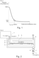
- the inventors of the present invention carried out a laboratory study specifically dedicated to measuring water absorption by previously torrefied wood pellets.
- the study consisted of a short, temperature-controlled torrefaction on representative pellet samples.
- a specific experimental device was created and the results obtained differ from what was commonly estimated by experts in the field.
- the optimum on the curve is the operating point allowing a granule with good hydrophobicity to be obtained while retaining a maximum of its heating capacity because the shorter the roasting time, the less mass and therefore energy the treated granule loses.
- the design of a system installation intended to produce hydrophobic biomass pellets can be optimized because it requires a short torrefaction, typically 20 minutes, at a relatively low temperature, typically 230 to 250°C, and with good control of the residence time. These are specific operating conditions for which the state of the art previously mentioned shows that industrial torrefactors are not suitable.
- the patent FR1182626 is a coffee roaster comprising a belt composed of vibrating trays so as to expose all sides of the beans to the heat of infrared radiation.
- the patent FR2213019 is an open-air coffee roasting system with a conveyor belt and infrared or ultrasonic heating.
- the patent FR2390202 describes a principle of coffee roasting in a fluidized bed (in a hot air flow) with a belt comprising paddles to carry the beans from the inlet to the outlet. Neither of these systems would be suitable for roasting biomass pellets since they are not airtight.
- the aim of the invention is therefore to respond at least in part to this need.
- the outlet of the furnace comprises at least one gas sealing device configured to evacuate the torrefied biomass pellets while ensuring a gas seal.
- the gas-tight device can advantageously consist of two valves mounted tilting one downstream of the other in the furnace outlet, forming an airlock, so as to evacuate the torrefied biomass pellets in batches while ensuring a gas-tight seal.
- the upstream valve is opened so that the volume of the airlock between the two valves is filled with a batch of biomass pellets, the downstream valve being closed.
- the upstream valve is closed and the downstream valve is opened in order to evacuate the batch of torrefied biomass pellets from the airlock.
- this evacuation takes place solely by gravity.
- the gas-tight device can also be made up of a rotary valve or any other mechanical device allowing the passage of torrefied pellets while ensuring a gas-tight seal.
- the sealed envelope is pierced with at least one gas outlet through which the gases resulting from the roasting are sucked in.
- the furnace is arranged below the pelletizing unit, the inlet of the furnace comprising at least one hopper for discharging the granules by gravity from the pelletizing unit to the conveying device(s).
- the outlet of the furnace comprises at least one hopper for evacuating by gravity the hydrophobic roasted granules from the sealed envelope.
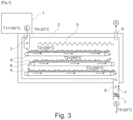
- the installation comprises several conveying devices arranged one after the other in the conveying direction inside the sealed envelope .
- This mode can allow a reduction in the length of the roasting oven and limit the external surface of the oven, thus reducing the thermal losses proportional to this external surface of the oven. For example, considering that the oven has a geometric shape of a rectangular parallelepiped, this external surface is minimal if we approach the shape of a cube.
- Each conveyor device is advantageously made up of a perforated conveyor belt. Such a device allows for precise control of the residence time of the pellets in the furnace, which is typically desired to be around 20 minutes.
- a conveyor belt any other device whose conveyance allows for a precise residence time can be considered.
- a bucket conveyor can be considered.
- the first given temperature (T1) is substantially equal to 100°C.
- the second given temperature (T2) is substantially between 230 and 250°C.
- the residence time in the oven is approximately between 20 and 25 min.
- the method comprises, simultaneously with step iii/ of roasting, a step v/ of suction of the gases resulting from the roasting with a view to their treatment or purification before release into the atmosphere.
- the invention essentially consists of adding, downstream of a biomass pelletization/granulation unit, a torrefaction oven which houses one or more conveying devices so that the biomass pellets remain within the oven for a short and precise time in order to optimize their hydrophobicity.
- the terms “input”, “output”, “upstream”, “downstream”, are used by reference to the directions of transfer of the biomass, of circulation of the torrefaction gas in the hydrophobic pellet production facility according to the present invention.
- roasting gas produced is low, it contains less than 15% combustible CO, hence a very low thermal capacity. It is therefore not economically viable to try to recover it by recovering the heat from its combustion, unlike what is generally implemented in industrial roasting units.
- the optimum point at 20 minutes and 250°C was obtained for softwood pellets. But depending on the biomass composing the pellets, the inventors found that these optimal conditions can vary slightly. For example, on hardwood pellets, the optimal torrefaction temperature is 230°C for the same duration of 20 minutes. However, this remains in the low range of torrefaction temperature levels and the amount of heating energy to carry out the heat treatment is low, this is one of the advantages of the proposed system.
- FIG. 2 illustrates a plant for producing hydrophobic biomass pellets according to the invention, arranged in an environment at temperature T0.
- the outlet of a pelletizing unit 1 is directly connected to the inlet E of a roasting oven 2, arranged below the pelletizing unit. More precisely, the inlet E comprises a hopper 3 for discharging the pellets by gravity from the pelletizing unit to the conveying device(s).
- the roasting oven firstly comprises a sealed and thermally insulated casing 2.
- At least one conveying device 4 is housed inside the sealed casing 2.
- the conveying device(s) is/are configured to guarantee an identical residence time for all the biomass pellets between the inlet E and the outlet S of the furnace.
- Each device is preferably a perforated metal conveyor belt. Any other equipment that meets the criterion of guaranteeing the residence time in the furnace, which is identical, may be suitable.
- a heating system 5 is also housed inside the sealed envelope, the heating system being configured to maintain the interior of the envelope 2 at a substantially constant roasting temperature T2.
- Many technical solutions are possible to ensure this function of maintaining a temperature T2, such as electric heating by means of electric resistors, by gas combustion, by means of a heat exchanger, etc.
- the homogeneity of the heating within the envelope 2 may require mixing by a ventilation device which can be integrated into the heating system 5.
- the quality of the thermal insulation of the casing 2 makes it possible to limit the loss of energy through the furnace but also to avoid condensation of tars.
- the fact that the temperature T2 is in the low range of usual roasting temperatures, typically between 230 and 250°C is a technical advantage because the thermal losses are proportional to the temperature difference T2-T0 and the production of a casing 2 with good thermal insulation of a furnace at 250°C is relatively easy with conventional materials.
- the outlet S of the furnace may comprise an outlet hopper 6 in order to evacuate the biomass pellets at the end of the torrefaction heat treatment to an environment at temperature T3.
- This outlet S may comprise at least one gas-tight device 7 configured to evacuate the torrefied biomass pellets while ensuring a gas-tight seal.
- this device 7 can consist of two valves mounted tilting one downstream of the other in the outlet S of the furnace, forming an airlock, so as to evacuate the torrefied biomass pellets in batches while ensuring a gas seal.
- the device 7 makes it possible to contain the roasting gas in the casing 2 of the oven.
- This gas is potentially dangerous and polluting, because it contains carbon monoxide CO and tars in vapor form.
- the evacuation of this gas G can be carried out by a gas outlet orifice 8 made by drilling through the wall of the top of the casing 2.
- the gas G can be sucked in through this orifice 8 for further treatment or combustion before release into the atmosphere.
- the suction must be sufficient to avoid gas release through possible leaks in the casing.
- Step i/ pelletization is carried out in unit 1 in order to obtain biomass pellets 9 at a given temperature T1.
- Step ii/ the biomass pellets 9 at temperature T1 in the envelope 2 are discharged by gravity using the inlet hopper 3.
- Step iii/ roasting is carried out by the heating system 5 at a given temperature T2 in the oven. Simultaneously with the implementation of the heating, the biomass pellets 9 are conveyed by the conveying device 7 inside the oven so as to guarantee a residence time in the oven. This predetermined residence time is substantially identical for all the pellets, in order to obtain hydrophobic biomass pellets 9.
- a step is carried out to suck up the gases G from roasting through the orifice 8 for treatment or purification before release into the atmosphere.
- Step iv/ the hydrophobic biomass pellets 9 are discharged by gravity through the outlet hopper 6. More precisely, the upstream valve of the device 7 is opened so that the volume of the airlock between the two valves is filled with a batch of biomass pellets, the downstream valve of the device 7 being closed. Then, the upstream valve is closed and the downstream valve is opened in order to discharge the batch of torrefied biomass pellets by gravity from the airlock.
- the energy integration of the pelletizing unit 1 in a roasting oven installation allows a gain on heating which can be estimated by calculation knowing the specific heat of the biomass, typically wood ( Cp wood ), the specific heat of the water liquid ( CP water ), the specific heat of the vapor ( Cp vapor ) and the latent heat of vaporization of water ( Lv water ).
- E torref HR % ⁇ Cp eau + 1 ⁇ HR % ⁇ Cp bois ⁇ 100 ⁇ T 0 + HR % ⁇ Lv eau + HR % ⁇ Cp tem + 1 ⁇ HR % ⁇ Cp bois ⁇ T 2 ⁇ 100
- the temperature of the pellets leaving the pelletizing unit T1 is equal to 100°C
- the roasting temperature T2 is equal to 250°C
- the residence time of the pellets in the oven being between 20 and 25 min.
- the moisture content of a pellet entering roasting oven 2 is considered to be 30%.
- this R gain would be 20% for pellets that only contain 14% moisture because the drier the pellets at the inlet, the greater the gain. It should be noted that this gain is a minimum because the calculation carried out does not take into account the exothermic reactions that take place during roasting.
- FIG. 3 illustrates a variant integrating several conveyor systems 7. This makes it possible to reduce the size of the roasting unit and to limit the external surface area of the oven, thus reducing heat losses.
Landscapes
- Chemical & Material Sciences (AREA)
- Oil, Petroleum & Natural Gas (AREA)
- Engineering & Computer Science (AREA)
- Organic Chemistry (AREA)
- Materials Engineering (AREA)
- Combustion & Propulsion (AREA)
- Life Sciences & Earth Sciences (AREA)
- Geology (AREA)
- Geochemistry & Mineralogy (AREA)
- General Life Sciences & Earth Sciences (AREA)
- Physics & Mathematics (AREA)
- Thermal Sciences (AREA)
- Environmental & Geological Engineering (AREA)
- Solid Fuels And Fuel-Associated Substances (AREA)
- Processing Of Solid Wastes (AREA)
Claims (12)
- Anlage zur Herstellung von hydrophoben Biomassepellets, umfassend:- eine Pelletierungseinheit (1), umfassend einen Auslass, durch den Biomassepellets (9) mit einer gegebenen Temperatur (T1) ausgetragen werden sollen;- einen Torrefizierungsofen, umfassend einen Einlass (E), der mit dem Auslass der Pelletierungseinheit verbunden ist, und einen Auslass (S), durch den die torrefizierten Biomassepellets (9) ausgetragen werden sollen, wobei der Torrefizierungsofen umfasst:• ein dichtes und thermisch isoliertes Gehäuse (2),• mindestens eine Fördervorrichtung (4) für die Biomassepellets (9), die im Innenraum des dichten Gehäuses aufgenommen ist und dazu ausgestaltet ist, eine identische Verweilzeit für alle Biomassepellets zwischen dem Einlass (E) und dem Auslass (S) zu garantieren,• mindestens ein Heizsystem (5), das im Innenraum des dichten Gehäuses aufgenommen ist, wobei das Heizsystem dazu ausgestaltet ist, den Innenraum des Gehäuses (2) auf einer im Wesentlichen konstanten Torrefizierungstemperatur (T2) zu halten,• an seinem Auslass (S) mindestens eine Gasabdichtungsvorrichtung (7), die dazu ausgestaltet ist, die torrefizierten Biomassepellets auszutragen und dabei eine Gasabdichtung zu gewährleisten.
- Anlage nach Anspruch 1, wobei die Gasabdichtungsvorrichtung (7) aus zwei Ventilen besteht, die schwenkbar hintereinander in dem Auslass (S) des Ofens gelagert sind, wobei sie eine Schleuse bilden, so dass die torrefizierten Biomassepellets chargenweise ausgetragen werden und dabei eine Gasabdichtung gewährleistet wird.
- Anlage nach einem der vorhergehenden Ansprüche, wobei das dichte Gehäuse (2) mit mindestens einem Gasauslass (8) durchbohrt ist, durch den die aus der Torrefizierung hervorgegangenen Gase abgesaugt werden.
- Anlage nach einem der vorhergehenden Ansprüche, wobei der Ofen unter der Pelletierungseinheit angeordnet ist, wobei der Einlass (E) des Ofens mindestens einen Trichter (3) umfasst, um per Schwerkraft die Pellets von der Pelletierungseinheit aus bis zu der(den) Fördervorrichtung(en) auszutragen.
- Anlage nach einem der vorhergehenden Ansprüche, wobei der Auslass (S) des Ofens mindestens einen Trichter (6) umfasst, um per Schwerkraft die hydrophoben torrefizierten Pellets aus dem dichten Gehäuse auszutragen.
- Anlage nach einem der vorhergehenden Ansprüche, umfassend mehrere Fördervorrichtungen (4), die in Förderrichtung nacheinander im Innenraum des dichten Gehäuses (2) angeordnet sind.
- Anlage nach einem der vorhergehenden Ansprüche, wobei jede Fördervorrichtung (4) aus einem perforierten Förderband besteht.
- Verfahren zur Herstellung von hydrophoben Biomassepellets, das insbesondere von einer Anlage nach einem der vorhergehenden Ansprüche durchgeführt wird, umfassend die folgenden Schritte:i/ Pelletieren, um Biomassepellets mit einer gegebenen ersten Temperatur (T1) zu erhalten;ii/ Einführen der Biomassepellets mit der gegebenen ersten Temperatur (T1) in einen Ofen;iii/ Torrefizieren bei einer gegebenen zweiten Temperatur (T2) in dem Ofen, wobei die Biomassepellets im Innenraum des Ofens gleichzeitig so gefördert werden, dass eine vorbestimmte Verweilzeit in dem Ofen garantiert ist, die für alle Pellets im Wesentlichen identisch ist, um hydrophobe Biomassepellets zu erhalten;iv/ Austragen der hydrophoben Biomassepellets aus dem Ofen.
- Verfahren nach Anspruch 8, wobei die gegebene erste Temperatur (T1) im Wesentlichen 100 °C beträgt.
- Verfahren nach Anspruch 8 oder 9, wobei die gegebene zweite Temperatur (T2) im Wesentlichen zwischen 230 und 250 °C liegt.
- Verfahren nach einem der Ansprüche 8 bis 10, wobei die Verweilzeit in dem Ofen im Wesentlichen zwischen 15 und 30 min, bevorzugt zwischen 20 und 25 min liegt.
- Verfahren nach einem der Ansprüche 8 bis 11, umfassend gleichzeitig mit dem Schritt iii/ des Torrefizierens einen Schritt v/ des Absaugens der aus der Torrefizierung hervorgegangenen Gase im Hinblick auf ihre Behandlung oder eine Reinigung vor ihrer Einleitung in die Atmosphäre.
Applications Claiming Priority (1)
| Application Number | Priority Date | Filing Date | Title |
|---|---|---|---|
| FR2112665A FR3129614A1 (fr) | 2021-11-29 | 2021-11-29 | Installation et procédé afférent de production de granulés de biomasse hydrophobes. |
Publications (2)
| Publication Number | Publication Date |
|---|---|
| EP4186589A1 EP4186589A1 (de) | 2023-05-31 |
| EP4186589B1 true EP4186589B1 (de) | 2025-03-19 |
Family
ID=80448789
Family Applications (1)
| Application Number | Title | Priority Date | Filing Date |
|---|---|---|---|
| EP22208877.5A Active EP4186589B1 (de) | 2021-11-29 | 2022-11-22 | Anlage und verfahren zur herstellung von hydrophoben biomassepellets |
Country Status (2)
| Country | Link |
|---|---|
| EP (1) | EP4186589B1 (de) |
| FR (1) | FR3129614A1 (de) |
Families Citing this family (1)
| Publication number | Priority date | Publication date | Assignee | Title |
|---|---|---|---|---|
| NL2035650B1 (en) | 2023-08-22 | 2025-03-04 | Yilkins B V | Method of manufacturing densified, torrefied biomass particulates |
Family Cites Families (19)
| Publication number | Priority date | Publication date | Assignee | Title |
|---|---|---|---|---|
| FR1182626A (fr) | 1957-09-11 | 1959-06-26 | Dispositif de torréfaction de graines et spécialement du café vert | |
| FR2213019A1 (en) | 1972-11-14 | 1974-08-02 | Poele Louis Olivie De | Continuous coffee roasting machine - using IR heaters in air, to give more uniform colour and better aroma |
| IT1067899B (it) | 1976-07-28 | 1985-03-21 | Schultz Richard | Cubettatrice di mangini in genere comportante rulli operatori pressanti con differente diametro |
| FR2390202A1 (fr) | 1977-05-11 | 1978-12-08 | Anvar | Procede et dispositif de traitement d'un produit se presentant sous forme de grains et application a la torrefaction |
| US4711622A (en) | 1984-07-04 | 1987-12-08 | Gebruder Buhler Ag | Pellet mill |
| NL8601270A (nl) | 1986-05-20 | 1987-12-16 | Aarsen Maschf Bv | Korrelpers. |
| BR112012009172A2 (pt) | 2009-10-30 | 2016-11-22 | Dieffenbacher Gmbh Maschinen | prensa granuladora para produzir grânulos |
| US9057037B2 (en) * | 2010-04-20 | 2015-06-16 | River Basin Energy, Inc. | Post torrefaction biomass pelletization |
| JP2013000940A (ja) | 2011-06-14 | 2013-01-07 | Takahama Industry Co Ltd | 木質ペレット製造用の押出成形機 |
| EP2729749A4 (de) | 2011-07-07 | 2015-04-08 | Torrefuels Inc | System und verfahren zur umwandlung von organischem material in ein torrezifiertes produkt |
| FR2982273B1 (fr) | 2011-11-09 | 2014-03-14 | Commissariat Energie Atomique | Reacteur de sechage et de torrefaction de biomasse, de preference ligno-cellulosique |
| FR2985043B1 (fr) | 2011-12-21 | 2014-02-21 | Commissariat Energie Atomique | Procede et dispositif de torrefaction rapide de biomasse |
| US9562204B2 (en) | 2012-09-14 | 2017-02-07 | Astec, Inc. | Method and apparatus for pelletizing blends of biomass materials for use as fuel |
| WO2014152931A1 (en) | 2013-03-15 | 2014-09-25 | Enginuity Worldwide, LLC | Moisture resistant biomass fuel compact and method of manufacturing |
| US20160152911A1 (en) * | 2013-07-17 | 2016-06-02 | Torrefusion Technologies Inc. | Process for Preparing Torrefied Biomass Material Using a Combustible Liquid |
| FR3024220B1 (fr) | 2014-07-28 | 2019-06-07 | Clauger | Cellule de refroidissement de denrees alimentaires a circulation d'air longitudinale ou transversale |
| FR3024221B1 (fr) | 2014-07-28 | 2016-08-05 | Commissariat Energie Atomique | Installation de sechage et de torrefaction de biomasse a rendement energetique ameliore |
| GB201501073D0 (en) | 2015-01-22 | 2015-03-11 | Univ Dublin | A method and apparatus for thermochemically processing material |
| US10961459B2 (en) * | 2018-08-20 | 2021-03-30 | Marc A. Seidner | System for production of a renewable liquid fuel |
-
2021
- 2021-11-29 FR FR2112665A patent/FR3129614A1/fr active Pending
-
2022
- 2022-11-22 EP EP22208877.5A patent/EP4186589B1/de active Active
Also Published As
| Publication number | Publication date |
|---|---|
| FR3129614A1 (fr) | 2023-06-02 |
| EP4186589A1 (de) | 2023-05-31 |
Similar Documents
| Publication | Publication Date | Title |
|---|---|---|
| EP2776540B1 (de) | Reaktor zur trocknung und torrefizierung einer biomasse, vorzugsweise einer lignocellulose- biomasse | |
| US9127227B2 (en) | Method and apparatus for processing biomass material | |
| EP2009353A1 (de) | Verfahren zur Vorbereitung einer gemischten Ladung, die Biomasse und einen schweren Verschnitt auf Kohlenwasserstoffbasis enthält, zur späteren Vergasung | |
| FR3087790A1 (fr) | Procede de fabrication en continu d'une matiere combustible pour chaudiere industrielle, matiere et installation correspondantes | |
| CA2195742C (fr) | Procede de recyclage des bois traites et l'installation de mise en oeuvre du procede | |
| EP2189512A1 (de) | Röstverfahren der Biomasse und Kontrolle dieses Verfahrens | |
| EP4186589B1 (de) | Anlage und verfahren zur herstellung von hydrophoben biomassepellets | |
| EP3856870B1 (de) | Mehrregalofen mit armen mit kratzerzähnen mit optimiertem profil, anwendung zum rösten von biomasse | |
| WO2020126311A1 (fr) | Reacteur tubulaire a vis convoyeuse | |
| EP3105306B1 (de) | Verfahren zur umwandlung von biomasse in mindestens eine biokohle | |
| FR3016955A1 (fr) | Procede et centrale de torrefaction de biomasse | |
| CA3152668A1 (fr) | Procede de pyrolyse de la biomasse ligneuse | |
| FR2921355A1 (fr) | Procede et installation de transformation de boues fermentescibles | |
| EP3173459A1 (de) | Reaktor für die schnellpyrolyse von organischen biomasseteilchen mit injektion von heissen gasen gegen den strom | |
| FR2551083A1 (fr) | Procede de fabrication a partir de materiaux carbones d'une boue aqueuse de combustible pouvant etre transportee | |
| WO2022248233A1 (fr) | Procede de fabrication en continu d'une matiere combustible par decompression explosive s'operant par paliers | |
| EP4610333A1 (de) | Verkohlungsanlage und verfahren zur herstellung von holzkohle | |
| WO2008125460A1 (fr) | Procedes et dispositifs de fabrication de charbon de bois ameliores | |
| EP4019871A1 (de) | Etagenofen mit gebogenen rohren, anwendung zum rösten von biomasse | |
| EP3878925A1 (de) | Herstellungsverfahren von bio-ölen durch pyrolyse von olivenzweigen | |
| WO2024217906A1 (fr) | Dispositif pour le traitement d'une charge solide comprenant le recyclage de la charge solide | |
| FR3148083A1 (fr) | Four à soles multiples pour mettre en contact un solide et un gaz | |
| WO2025185837A1 (fr) | Systeme et procede de production de biochar par séchage et pyrolyse lente d'un materiau lignocellulosique sous atmosphere co2 | |
| WO2015091492A1 (fr) | Procede de torrefaction d'une charge carbonee comprenant une etape de sechage optimisee | |
| OA17883A (fr) | Procédé de transformation d'une biomasse en au moins un biocharbon. |
Legal Events
| Date | Code | Title | Description |
|---|---|---|---|
| PUAI | Public reference made under article 153(3) epc to a published international application that has entered the european phase |
Free format text: ORIGINAL CODE: 0009012 |
|
| STAA | Information on the status of an ep patent application or granted ep patent |
Free format text: STATUS: REQUEST FOR EXAMINATION WAS MADE |
|
| 17P | Request for examination filed |
Effective date: 20221122 |
|
| AK | Designated contracting states |
Kind code of ref document: A1 Designated state(s): AL AT BE BG CH CY CZ DE DK EE ES FI FR GB GR HR HU IE IS IT LI LT LU LV MC ME MK MT NL NO PL PT RO RS SE SI SK SM TR |
|
| RAP3 | Party data changed (applicant data changed or rights of an application transferred) |
Owner name: COMMISSARIAT A L'ENERGIE ATOMIQUE ET AUX ENERGIESALTERNATIVES |
|
| GRAP | Despatch of communication of intention to grant a patent |
Free format text: ORIGINAL CODE: EPIDOSNIGR1 |
|
| STAA | Information on the status of an ep patent application or granted ep patent |
Free format text: STATUS: GRANT OF PATENT IS INTENDED |
|
| INTG | Intention to grant announced |
Effective date: 20241114 |
|
| GRAS | Grant fee paid |
Free format text: ORIGINAL CODE: EPIDOSNIGR3 |
|
| GRAA | (expected) grant |
Free format text: ORIGINAL CODE: 0009210 |
|
| STAA | Information on the status of an ep patent application or granted ep patent |
Free format text: STATUS: THE PATENT HAS BEEN GRANTED |
|
| AK | Designated contracting states |
Kind code of ref document: B1 Designated state(s): AL AT BE BG CH CY CZ DE DK EE ES FI FR GB GR HR HU IE IS IT LI LT LU LV MC ME MK MT NL NO PL PT RO RS SE SI SK SM TR |
|
| REG | Reference to a national code |
Ref country code: GB Ref legal event code: FG4D Free format text: NOT ENGLISH |
|
| REG | Reference to a national code |
Ref country code: CH Ref legal event code: EP |
|
| REG | Reference to a national code |
Ref country code: DE Ref legal event code: R096 Ref document number: 602022011934 Country of ref document: DE |
|
| REG | Reference to a national code |
Ref country code: IE Ref legal event code: FG4D Free format text: LANGUAGE OF EP DOCUMENT: FRENCH |
|
| PG25 | Lapsed in a contracting state [announced via postgrant information from national office to epo] |
Ref country code: RS Free format text: LAPSE BECAUSE OF FAILURE TO SUBMIT A TRANSLATION OF THE DESCRIPTION OR TO PAY THE FEE WITHIN THE PRESCRIBED TIME-LIMIT Effective date: 20250619 |
|
| PG25 | Lapsed in a contracting state [announced via postgrant information from national office to epo] |
Ref country code: FI Free format text: LAPSE BECAUSE OF FAILURE TO SUBMIT A TRANSLATION OF THE DESCRIPTION OR TO PAY THE FEE WITHIN THE PRESCRIBED TIME-LIMIT Effective date: 20250319 |
|
| REG | Reference to a national code |
Ref country code: LT Ref legal event code: MG9D |
|
| PG25 | Lapsed in a contracting state [announced via postgrant information from national office to epo] |
Ref country code: NO Free format text: LAPSE BECAUSE OF FAILURE TO SUBMIT A TRANSLATION OF THE DESCRIPTION OR TO PAY THE FEE WITHIN THE PRESCRIBED TIME-LIMIT Effective date: 20250619 |
|
| PG25 | Lapsed in a contracting state [announced via postgrant information from national office to epo] |
Ref country code: HR Free format text: LAPSE BECAUSE OF FAILURE TO SUBMIT A TRANSLATION OF THE DESCRIPTION OR TO PAY THE FEE WITHIN THE PRESCRIBED TIME-LIMIT Effective date: 20250319 |
|
| PG25 | Lapsed in a contracting state [announced via postgrant information from national office to epo] |
Ref country code: LV Free format text: LAPSE BECAUSE OF FAILURE TO SUBMIT A TRANSLATION OF THE DESCRIPTION OR TO PAY THE FEE WITHIN THE PRESCRIBED TIME-LIMIT Effective date: 20250319 |
|
| PG25 | Lapsed in a contracting state [announced via postgrant information from national office to epo] |
Ref country code: BG Free format text: LAPSE BECAUSE OF FAILURE TO SUBMIT A TRANSLATION OF THE DESCRIPTION OR TO PAY THE FEE WITHIN THE PRESCRIBED TIME-LIMIT Effective date: 20250319 Ref country code: GR Free format text: LAPSE BECAUSE OF FAILURE TO SUBMIT A TRANSLATION OF THE DESCRIPTION OR TO PAY THE FEE WITHIN THE PRESCRIBED TIME-LIMIT Effective date: 20250620 |
|
| REG | Reference to a national code |
Ref country code: NL Ref legal event code: MP Effective date: 20250319 |
|
| REG | Reference to a national code |
Ref country code: AT Ref legal event code: MK05 Ref document number: 1776524 Country of ref document: AT Kind code of ref document: T Effective date: 20250319 |
|
| PG25 | Lapsed in a contracting state [announced via postgrant information from national office to epo] |
Ref country code: NL Free format text: LAPSE BECAUSE OF FAILURE TO SUBMIT A TRANSLATION OF THE DESCRIPTION OR TO PAY THE FEE WITHIN THE PRESCRIBED TIME-LIMIT Effective date: 20250319 |
|
| PG25 | Lapsed in a contracting state [announced via postgrant information from national office to epo] |
Ref country code: SE Free format text: LAPSE BECAUSE OF FAILURE TO SUBMIT A TRANSLATION OF THE DESCRIPTION OR TO PAY THE FEE WITHIN THE PRESCRIBED TIME-LIMIT Effective date: 20250319 |
|
| PG25 | Lapsed in a contracting state [announced via postgrant information from national office to epo] |
Ref country code: SM Free format text: LAPSE BECAUSE OF FAILURE TO SUBMIT A TRANSLATION OF THE DESCRIPTION OR TO PAY THE FEE WITHIN THE PRESCRIBED TIME-LIMIT Effective date: 20250319 |
|
| PG25 | Lapsed in a contracting state [announced via postgrant information from national office to epo] |
Ref country code: PT Free format text: LAPSE BECAUSE OF FAILURE TO SUBMIT A TRANSLATION OF THE DESCRIPTION OR TO PAY THE FEE WITHIN THE PRESCRIBED TIME-LIMIT Effective date: 20250721 Ref country code: ES Free format text: LAPSE BECAUSE OF FAILURE TO SUBMIT A TRANSLATION OF THE DESCRIPTION OR TO PAY THE FEE WITHIN THE PRESCRIBED TIME-LIMIT Effective date: 20250319 |
|
| PG25 | Lapsed in a contracting state [announced via postgrant information from national office to epo] |
Ref country code: PL Free format text: LAPSE BECAUSE OF FAILURE TO SUBMIT A TRANSLATION OF THE DESCRIPTION OR TO PAY THE FEE WITHIN THE PRESCRIBED TIME-LIMIT Effective date: 20250319 Ref country code: IT Free format text: LAPSE BECAUSE OF FAILURE TO SUBMIT A TRANSLATION OF THE DESCRIPTION OR TO PAY THE FEE WITHIN THE PRESCRIBED TIME-LIMIT Effective date: 20250319 |
|
| PG25 | Lapsed in a contracting state [announced via postgrant information from national office to epo] |
Ref country code: AT Free format text: LAPSE BECAUSE OF FAILURE TO SUBMIT A TRANSLATION OF THE DESCRIPTION OR TO PAY THE FEE WITHIN THE PRESCRIBED TIME-LIMIT Effective date: 20250319 |
|
| PG25 | Lapsed in a contracting state [announced via postgrant information from national office to epo] |
Ref country code: CZ Free format text: LAPSE BECAUSE OF FAILURE TO SUBMIT A TRANSLATION OF THE DESCRIPTION OR TO PAY THE FEE WITHIN THE PRESCRIBED TIME-LIMIT Effective date: 20250319 Ref country code: EE Free format text: LAPSE BECAUSE OF FAILURE TO SUBMIT A TRANSLATION OF THE DESCRIPTION OR TO PAY THE FEE WITHIN THE PRESCRIBED TIME-LIMIT Effective date: 20250319 |
|
| PG25 | Lapsed in a contracting state [announced via postgrant information from national office to epo] |
Ref country code: RO Free format text: LAPSE BECAUSE OF FAILURE TO SUBMIT A TRANSLATION OF THE DESCRIPTION OR TO PAY THE FEE WITHIN THE PRESCRIBED TIME-LIMIT Effective date: 20250319 |
|
| PG25 | Lapsed in a contracting state [announced via postgrant information from national office to epo] |
Ref country code: SK Free format text: LAPSE BECAUSE OF FAILURE TO SUBMIT A TRANSLATION OF THE DESCRIPTION OR TO PAY THE FEE WITHIN THE PRESCRIBED TIME-LIMIT Effective date: 20250319 |
|
| PG25 | Lapsed in a contracting state [announced via postgrant information from national office to epo] |
Ref country code: IS Free format text: LAPSE BECAUSE OF FAILURE TO SUBMIT A TRANSLATION OF THE DESCRIPTION OR TO PAY THE FEE WITHIN THE PRESCRIBED TIME-LIMIT Effective date: 20250719 |
|
| PG25 | Lapsed in a contracting state [announced via postgrant information from national office to epo] |
Ref country code: DK Free format text: LAPSE BECAUSE OF FAILURE TO SUBMIT A TRANSLATION OF THE DESCRIPTION OR TO PAY THE FEE WITHIN THE PRESCRIBED TIME-LIMIT Effective date: 20250319 |
|
| PGFP | Annual fee paid to national office [announced via postgrant information from national office to epo] |
Ref country code: FR Payment date: 20251125 Year of fee payment: 4 |