EP3799549A1 - Haltevorrichtung zur thermischen kontaktierung eines auf einer leiterplatte montierten elektronischen bauteils mit einem kühlkörper - Google Patents
Haltevorrichtung zur thermischen kontaktierung eines auf einer leiterplatte montierten elektronischen bauteils mit einem kühlkörper Download PDFInfo
- Publication number
- EP3799549A1 EP3799549A1 EP20190649.2A EP20190649A EP3799549A1 EP 3799549 A1 EP3799549 A1 EP 3799549A1 EP 20190649 A EP20190649 A EP 20190649A EP 3799549 A1 EP3799549 A1 EP 3799549A1
- Authority
- EP
- European Patent Office
- Prior art keywords
- holding device
- holding
- electronic component
- circuit board
- cavity
- Prior art date
- Legal status (The legal status is an assumption and is not a legal conclusion. Google has not performed a legal analysis and makes no representation as to the accuracy of the status listed.)
- Granted
Links
Images

Classifications
-
- H—ELECTRICITY
- H05—ELECTRIC TECHNIQUES NOT OTHERWISE PROVIDED FOR
- H05K—PRINTED CIRCUITS; CASINGS OR CONSTRUCTIONAL DETAILS OF ELECTRIC APPARATUS; MANUFACTURE OF ASSEMBLAGES OF ELECTRICAL COMPONENTS
- H05K1/00—Printed circuits
- H05K1/02—Details
- H05K1/0201—Thermal arrangements, e.g. for cooling, heating or preventing overheating
- H05K1/0203—Cooling of mounted components
- H05K1/0209—External configuration of printed circuit board adapted for heat dissipation, e.g. lay-out of conductors, coatings
-
- H—ELECTRICITY
- H05—ELECTRIC TECHNIQUES NOT OTHERWISE PROVIDED FOR
- H05K—PRINTED CIRCUITS; CASINGS OR CONSTRUCTIONAL DETAILS OF ELECTRIC APPARATUS; MANUFACTURE OF ASSEMBLAGES OF ELECTRICAL COMPONENTS
- H05K7/00—Constructional details common to different types of electric apparatus
- H05K7/20—Modifications to facilitate cooling, ventilating, or heating
- H05K7/2039—Modifications to facilitate cooling, ventilating, or heating characterised by the heat transfer by conduction from the heat generating element to a dissipating body
- H05K7/20409—Outer radiating structures on heat dissipating housings, e.g. fins integrated with the housing
-
- H—ELECTRICITY
- H05—ELECTRIC TECHNIQUES NOT OTHERWISE PROVIDED FOR
- H05K—PRINTED CIRCUITS; CASINGS OR CONSTRUCTIONAL DETAILS OF ELECTRIC APPARATUS; MANUFACTURE OF ASSEMBLAGES OF ELECTRICAL COMPONENTS
- H05K7/00—Constructional details common to different types of electric apparatus
- H05K7/20—Modifications to facilitate cooling, ventilating, or heating
- H05K7/2039—Modifications to facilitate cooling, ventilating, or heating characterised by the heat transfer by conduction from the heat generating element to a dissipating body
- H05K7/20436—Inner thermal coupling elements in heat dissipating housings, e.g. protrusions or depressions integrally formed in the housing
- H05K7/20445—Inner thermal coupling elements in heat dissipating housings, e.g. protrusions or depressions integrally formed in the housing the coupling element being an additional piece, e.g. thermal standoff
-
- H—ELECTRICITY
- H05—ELECTRIC TECHNIQUES NOT OTHERWISE PROVIDED FOR
- H05K—PRINTED CIRCUITS; CASINGS OR CONSTRUCTIONAL DETAILS OF ELECTRIC APPARATUS; MANUFACTURE OF ASSEMBLAGES OF ELECTRICAL COMPONENTS
- H05K7/00—Constructional details common to different types of electric apparatus
- H05K7/20—Modifications to facilitate cooling, ventilating, or heating
- H05K7/2039—Modifications to facilitate cooling, ventilating, or heating characterised by the heat transfer by conduction from the heat generating element to a dissipating body
- H05K7/20436—Inner thermal coupling elements in heat dissipating housings, e.g. protrusions or depressions integrally formed in the housing
- H05K7/2049—Pressing means used to urge contact, e.g. springs
-
- H—ELECTRICITY
- H05—ELECTRIC TECHNIQUES NOT OTHERWISE PROVIDED FOR
- H05K—PRINTED CIRCUITS; CASINGS OR CONSTRUCTIONAL DETAILS OF ELECTRIC APPARATUS; MANUFACTURE OF ASSEMBLAGES OF ELECTRICAL COMPONENTS
- H05K7/00—Constructional details common to different types of electric apparatus
- H05K7/20—Modifications to facilitate cooling, ventilating, or heating
- H05K7/2039—Modifications to facilitate cooling, ventilating, or heating characterised by the heat transfer by conduction from the heat generating element to a dissipating body
- H05K7/205—Heat-dissipating body thermally connected to heat generating element via thermal paths through printed circuit board [PCB]
-
- H—ELECTRICITY
- H05—ELECTRIC TECHNIQUES NOT OTHERWISE PROVIDED FOR
- H05K—PRINTED CIRCUITS; CASINGS OR CONSTRUCTIONAL DETAILS OF ELECTRIC APPARATUS; MANUFACTURE OF ASSEMBLAGES OF ELECTRICAL COMPONENTS
- H05K7/00—Constructional details common to different types of electric apparatus
- H05K7/20—Modifications to facilitate cooling, ventilating, or heating
- H05K7/2089—Modifications to facilitate cooling, ventilating, or heating for power electronics, e.g. for inverters for controlling motor
- H05K7/209—Heat transfer by conduction from internal heat source to heat radiating structure
-
- H—ELECTRICITY
- H10—SEMICONDUCTOR DEVICES; ELECTRIC SOLID-STATE DEVICES NOT OTHERWISE PROVIDED FOR
- H10W—GENERIC PACKAGES, INTERCONNECTIONS, CONNECTORS OR OTHER CONSTRUCTIONAL DETAILS OF DEVICES COVERED BY CLASS H10
- H10W40/00—Arrangements for thermal protection or thermal control
- H10W40/60—Securing means for detachable heating or cooling arrangements, e.g. clamps
-
- H—ELECTRICITY
- H10—SEMICONDUCTOR DEVICES; ELECTRIC SOLID-STATE DEVICES NOT OTHERWISE PROVIDED FOR
- H10W—GENERIC PACKAGES, INTERCONNECTIONS, CONNECTORS OR OTHER CONSTRUCTIONAL DETAILS OF DEVICES COVERED BY CLASS H10
- H10W40/00—Arrangements for thermal protection or thermal control
- H10W40/60—Securing means for detachable heating or cooling arrangements, e.g. clamps
- H10W40/611—Bolts or screws
-
- H—ELECTRICITY
- H10—SEMICONDUCTOR DEVICES; ELECTRIC SOLID-STATE DEVICES NOT OTHERWISE PROVIDED FOR
- H10W—GENERIC PACKAGES, INTERCONNECTIONS, CONNECTORS OR OTHER CONSTRUCTIONAL DETAILS OF DEVICES COVERED BY CLASS H10
- H10W40/00—Arrangements for thermal protection or thermal control
- H10W40/10—Arrangements for heating
-
- H—ELECTRICITY
- H10—SEMICONDUCTOR DEVICES; ELECTRIC SOLID-STATE DEVICES NOT OTHERWISE PROVIDED FOR
- H10W—GENERIC PACKAGES, INTERCONNECTIONS, CONNECTORS OR OTHER CONSTRUCTIONAL DETAILS OF DEVICES COVERED BY CLASS H10
- H10W40/00—Arrangements for thermal protection or thermal control
- H10W40/20—Arrangements for cooling
- H10W40/231—Arrangements for cooling characterised by their places of attachment or cooling paths
- H10W40/235—Arrangements for cooling characterised by their places of attachment or cooling paths attached to package parts
Definitions
- the invention relates to a holding device for thermal contacting of an electronic component mounted on a printed circuit board with a heat sink.
- the heat sinks are large or heavy, or if they are integral with a housing, which receives the circuit board and the electronic component, it is often provided that the electronic components are not thermally connected to the heat sink until the circuit board is installed in the housing that receives the circuit board.
- the known solutions usually have several disadvantages.
- the heat conducting pad and the clamping element must be preassembled in two successive steps in the housing or on the heat sink.
- the printed circuit board which can also be referred to as a circuit board, is then inserted into the housing and the clamping element is finally assembled, as a result of which the electronic component is pressed by the clamping element against the heat-conducting pad and the heat sink.
- thermal pads are usually standard components and the mutually facing and corresponding surfaces of the electronic component and heat sink are not necessarily parallel to each other, the known solutions usually cannot compensate for an offset or an angle between the surfaces.
- the heat conducting pad or in the event that the electronic component does not fully contact the heat conducting pad, the heat is usually only insufficiently dissipated from the electronic component to the heat sink, which can result in damage to the component during operation.
- the assembly sequence can have a negative effect on the cooling process, since the clamping element in the prior art is usually finally assembled in the housing after the printed circuit board.
- the power module or the electronic component is already fixed on its pin side on the circuit board and the deflection width of the component or a deflection angle by which the component has to be deflected or tilted towards the heat conducting pad includes all tolerances that occur in the Assembly of the circuit board can occur.
- the deflection angle of the electronic component is due to the assembly process and the draft angle of the Housing or the heat sink arranged in opposite directions, whereby no parallel connection of the surfaces of the electronic component to the electronics housing or the heat sink is possible, so that an air gap or air inclusions between the electronic component and the heat sink can occur.
- the invention is therefore based on the object of overcoming the aforementioned disadvantages and providing a holding device for thermal contacting of an electronic component mounted on a printed circuit board with a heat sink, by means of which the thermal contacting can be produced inexpensively and at the same time in a process-reliable manner.
- a holding device for thermal contacting of an electronic component mounted on a printed circuit board with a heat sink having a holding body, a spring element and a tensioning element.
- the holding body forms a cavity corresponding to the electronic component for receiving the electronic component and has a connection section and a thermally conductive heat conducting section adjoining the cavity.
- the heat-conducting section has a thermal connection surface facing away from the cavity, which is preferably designed to lie full-surface on the heat sink in a fully assembled state, so that the heat-conducting section on its side facing the cavity is in particular full-surface on the electronic component and on the thermal connection surface rests against the heat sink and connects them thermally.
- the tensioning element is also designed to tension the spring element, the spring element being designed to be supported in a tensioned state on a counter-holding element and a To exert force on the holding body and / or the component that can be received in the cavity of the holding body and to move the holding body with the connection surface preferably essentially orthogonally to the connection surface on the cooling body and / or to press it against the cooling body.
- the holding device can comprise the counter-holding element, it being preferably provided that the counter-holding element is essentially stationary with respect to the printed circuit board and / or the heat sink.
- the counter-holding element can also be formed integrally with the heat sink or, for example, with the printed circuit board.
- the electronic component is preferably electronic components which are designed with a "Single In-Line Package" (SIP) or in German with a single-row housing, which therefore have a single row of pins or contact pins which they can be contacted on the circuit board.
- such components can be power modules for converting electrical energy, which heat up during operation, so that the heat has to be dissipated to avoid damage to the component itself and surrounding electronics.
- other electronics having a housing can also be considered, which are heated and cooled during operation or have to be connected to a heat sink.
- the holding device can also accommodate housings of the type TO-220, the holding device or the cavity of the holding body having to be designed to correspond to the respective electronic component.
- the holding body is preferably designed in such a way that the component with the heat dissipation surface points towards the heat-conducting section and rests against it can be added to the cavity.
- the proposed holding device is preferably used for the thermal contacting of an electronic component of a motor controller with a heat sink, the motor controller being arranged in a housing or housing cover of an electric motor and wherein the housing or the housing cover has cooling fins and is formed integrally as the heat sink.
- the electric motor preferably drives a fan or fan or is integrally formed as such.
- connection section is dimensionally stable and, for example, made of a thermoplastic, in particular at the temperatures prevailing when the holding device is used as intended.
- the heat conducting section is also formed from a thermally conductive thermoplastic elastomer.
- the connection section can thus be referred to as a hard component and the heat-conducting section as a soft component of the holding body.
- the soft component can be deformed by the action of heat of the electronic component and adapt to both the electronic component and the adjacent area of the heat sink and, by means of plastic deformation, can be in a form-fitting manner and displace any air inclusions.
- the holding body is also designed in one piece and in particular the connection section is connected to the heat-conducting section in a materially bonded manner.
- the holding body can be produced, for example, in a multi-component injection molding process or, here, in a two-component injection molding process, wherein the hard component can be formed from a thermoplastic and the soft component from a thermoplastic elastomer, as described.
- Holding device provided that a wall surrounding the cavity is formed by the connection section and the heat conducting section.
- the wall is divided into several wall sections, a wall section preferably being assigned to one side of the electronic component and a wall section being formed by the connection section or the connection section and the heat conducting section.
- the wall sections are preferably each at least partially in contact with the electronic component, so that the latter is held in a fixed position in the cavity by opposing wall sections.
- connection section surrounds the heat conducting section in the shape of a frame.
- the holding body has an opening connected to the cavity, through which the electronic component can be inserted into the cavity.
- the opening faces the printed circuit board on which the electronic component is mounted.
- the holding body has five wall sections which each adjoin the cavity or an electronic component that can be accommodated therein, as well as an opening which replaces a sixth wall section, so that the cavity of the holding body is separated from the five wall sections and the Opening is intended.
- the heat-conducting section can extend over one or more wall sections, the heat-conducting section being framed by the connection section.
- a section of the wall facing the heat sink can also be in one Cross-section be wedge-shaped, so that an angular offset between a substantially vertically running surface of the electronic component facing the heat-conducting section and a surface of the cooling body that runs obliquely to it and which the connection surface faces can be compensated for.
- the surface of the cooling body facing the connection surface, against which the connection surface is pressed, is designed obliquely, in particular in the case of heat sinks produced by a casting process, due to a demolding bevel necessary for removal from the mold.
- spacers are provided, which are, for example, integrally formed by the connection section and separate from the connection section or the Hard components extend like a web into the heat conducting section or into the soft component and through which the minimum distance between the electronic component and the heat sink is predetermined. If the electronic component comes to rest on the spacers and the spacers on the heat sink, they cannot come closer to one another, so that a predetermined minimum distance cannot be fallen below regardless of a possible plastic deformation of the heat conducting section.
- the tensioning element and the spring element are received on the connection section.
- connection section forms first latching elements and second latching elements, the first latching elements holding the tensioning element and the second latching elements holding the spring element on the connection section. It can be provided be that the tensioning element and the spring element are movably received and the area in which they can move is limited by the first and second latching elements.
- the holding device in its entirety with its interconnected components can be made available, stored, gripped and mounted.
- the spring element and tensioning element can move relative to the holding body within the scope of what the latching elements allow, they are non-detachably connected to one another, so that the holding device is designed as a multi-component but in one piece.
- the holding body forms third latching elements which protrude into the cavity and are formed in the To fix cavity recordable electronic component in the cavity.
- the electronic component can have locking recesses.
- the third latching elements can, for example, also encompass an edge of the electronic component pointing towards the printed circuit board.
- the holding body has fourth latching elements which extend to the circuit board on which the electronic Component is mounted or is mountable, and the holding device can be fixed with the fourth latching elements on the circuit board.
- the circuit board can have locking openings, in which the fourth latching elements can engage, these latching openings also being able to be elongated so that the holding device with the electronic component received therein can move towards the heat sink by the tensioning of the spring element.
- the spring element is a leaf spring which has a first edge and a second edge spaced apart from the first edge in the longitudinal direction of the leaf spring, the spacing of which increases when the spring element is tensioned by the tensioning element. This is achieved in that the height of the leaf spring is reduced by tensioning against the spring force and the ends or edges of the leaf spring are spread apart.
- the first edge is designed to be supported on the counter-holding element in the tensioned state and the second edge is designed to lie against the holding body and / or the component that can be received in the cavity of the holding body in the tensioned state.
- the tensioning element is a screw and the counter-holding element has a thread into which the screw can be screwed.
- the leaf spring is preferably clamped between the screw head or a washer adjacent to the screw head and the counter-holding element, the screw running through the leaf spring through an opening in the leaf spring, so that when the screw is screwed into the counter-holding element, the distance between the screw head and the counter-holding element reduced and the leaf spring thus compressed or their edges spread apart.
- a body having the thread is part of the tensioning element.
- the tensioning element can be a screw and a nut or a screw and a plate, which has a thread, so that the screw head and the nut or plate move towards one another by screwing, and the spring element compress or tighten between them so that it spreads and thereby displaces the holding body.
- Another aspect of the invention relates to a printed circuit board with an electronic component and a holding device according to the invention.
- circuit board has an opening through which the tensioning element can be actuated and the spring element can be tensioned by the tensioning element. If the tensioning element is a screw, this can be screwed into the counter-element, for example, using a screwdriver inserted through the opening in the circuit board.
- an advantageous embodiment of the circuit board provides that the holding device is attached to the circuit board with the fourth latching elements and the position of the electronic component received in the cavity of the holding device is predetermined for mounting the electronic component on the circuit board.
- the assembly can take place, for example, in that contact pins or pins of the electronic component are soldered to contact surfaces provided on the circuit board.
- Another aspect of the invention also relates to an electronics module or module with a housing, a heat sink, a printed circuit board according to the invention or with a printed circuit board and a holding device according to the invention.
- an embodiment of the module is advantageous in which the counter-holding element is formed integrally by the housing and the holding device can be fastened to the housing via the counter-holding element.
- the housing or the counter-holding element can for example have a thread into which a tensioning element designed as a screw can be screwed.
- the clamping element can also be used as a Latching pin can be provided, the counter-holding element or the housing for this purpose providing a corresponding latching opening into which the latching pin can be inserted, so that the spring element is compressed by the latching pin latched into the latching opening and the holding body is displaced or pressed against the heat sink.
- a particularly advantageous variant of the module provides that the housing integrally forms the heat sink.
- a first advantageous assembly method provides that the electronic component is first assembled on the circuit board and electrically connected to it. Subsequently or already beforehand, the holding device is plugged onto the electronic component, so that the electronic component is received in the cavity of the holding body.
- the circuit board with the electronic component mounted on it and the holding device is arranged in a housing or on a heat sink, but not yet fixed.
- tensioning the spring element By tensioning the spring element, the holding body and the loosely inserted circuit board are pushed against the cooling body or pressed against a surface of the cooling body opposite the connection surface of the holding body. Only after the end position is determined by the tensioning of the spring element and the electronic component is in thermal contact with the heat sink, the circuit board is fixed on the housing or on the heat sink, which can be done, for example, by screwing.
- An alternative, second, but also advantageous assembly method provides that the electronic component is inserted into the holding device and fixed to the circuit board by the fourth latching elements of the holding device, so that the electronic component is held in a predetermined position by the holding device on the circuit board. Subsequently, the electronic component can be electrically contacted with the circuit board or the connection points of the circuit board provided for this purpose by soldering.
- the holding device and the electronic component can also already be provided as an assembly.
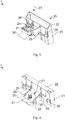
- FIG 1 the holding device 1 having three components is shown, the three components, that is to say the holding body 20, the tensioning element 10 and the spring element 30, being separated from one another.
- the holding body 20 alone is also rotated in FIG Figure 2 pictured.
- the holding device 1 with its captively connected components is in the Figures 3 and 4 pictured.
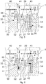
- the Figures 5 and 6 show as a sectional view various assembly states of the Figures 1 to 4 Holding device 1 shown, so that the following description applies essentially to all figures.
- the holding body 20 forms four first latching elements 24 on its connection section 21, which are designed to encompass the screw head 11 of the tensioning element 10, which is embodied as a screw, and thereby captive the tensioning element 10 on the holding body 20. Furthermore, the holding body 20 forms four second latching elements 25 on its connection section 21, which are designed to encompass the opposite side edges of the spring element 30, which is designed as a leaf spring, and thereby also to connect the spring element 30 to the holding body 20 in a captive manner.
- the cavity of the holding body 20 is determined by both the connection section 21 and the heat conducting section 22 of the holding body 20, the cavity being opened by an opening 23 through which the electronic component 42 can be introduced or inserted into the cavity.
- the heat conducting section 22 is formed from a thermally conductive material and rests in the direction of the cavity on the electronic component 42 or a heat dissipating surface of the electronic component 42 received therein. Pointing away from the cavity, the heat conducting section 22 forms a connection surface 28 with which it rests or can rest against the cooling body 54 in a final assembled state.
- the heat conducting section 22 is, as it is in particular by the Figures 2 and 4th is visible, encircle the connection section 21 in a frame-like manner or comprises, wherein the heat conducting section 22 extends over two wall sections.
- the connection section 21 is preferably formed from a thermoplastic and remains fixed at the temperatures prevailing during normal use, so that the connection section 21 can be referred to as a hard component that holds both the other components of the holding device 1 and the heat-conducting section 22.
- the heat-conducting section 22 is also formed from a thermoplastic elastomer, which can be plastically deformed under the influence of temperature, so that the heat-conducting section 22 clings flush against both the heat sink 54 and the electronic component 42 under the temperatures prevailing during normal use.
- two spaced-apart third latching elements 26 are also provided, which extend with a latching nose into the cavity and are each designed to latch with a latching recess provided in the electronic component 42.
- the projections of the locking elements 26 extending away from the cavity are each actuating elements which can be operated by a tool or by hand in order to release the locking lugs of the locking elements 26 from locking with the component 42 and to remove the component 42 more easily from the cavity to be able to.
- FIG. 4 which the holding device 1 from a, based on the representation of the holding device 1 in the Figures 1 to 3 , shows the lower view
- the spring element 30 is held by a total of four second latching elements 25 which are opposite one another in pairs, with a recess 32 being provided in the spring element 30 through which a guide web 27 formed by the connecting section 21 of the holding body 20 runs.
- the tensioning element 10 is designed as a screw, a section of which runs through the spring element 30, for which an opening 31 is provided in the spring element 30.
- the sectional view of the Figure 5 shows part of a housing 50, which integrally forms both the counter-holding element 51 and the heat sink 54, wherein a circuit board 40 is arranged in the housing 50.
- a circuit board 40 is arranged in the housing 50.
- the area where the electronic component 42 provided on the circuit board 40 is connected to the heat sink 54 is covered.
- a holding device 1 is attached to the component 42.
- the circuit board 40 is inserted into the housing with its electronic component 42 and the holding device 1 attached to it.
- the printed circuit board 40 can then be fixed to the housing 50 at connection points (not shown).
- the clamping element 10 which is designed as a screw, is rotated through the opening 41 in the circuit board 40 with the aid of a tool or with the aid of a screwdriver, which is inserted into the receptacle of the screw head 11, and thereby screwed into a thread 52 which is in the counter-holding element 51 is trained.
- the tensioning element 10 designed as a screw is held on the holding body 20 in such a way that the screw head 11 can move relative to the illustration of FIG Figures 5 and 6 is limited upwards by the first latching elements 24 and downwards by the spring element 30, the mobility of which is in turn limited upwards by the connection section 21 and downwards by the second latching elements 25.
- a mobility of the tensioning element 10 and the spring element 30 orthogonally thereto or to the sides is limited in each case by the respective latching elements 24, 25 or by the connecting element and, with respect to the spring element 30, in particular by the guide web 27.
- the tensioning element 10 and the spring element 30 can at least partially detach themselves from the holding body 20 or from the latching with the respective latching elements 24, 25, whereby these still remain in a predetermined position guided by the guide web 27 and the holding body 20 Press against the heat sink 54.
- the wall section adjoining or adjacent to the heat sink 54 has a wedge shape tapering downwards in the illustration, through which an angular offset between the essentially vertical surface of the electronic component 42 which faces the heat sink 54 , and the connection surface 53 of the cooling body 54, which is designed as an inclined draft angle, compensates.
- the clamping element 10 is screwed with a tool reaching through the opening 41 of the circuit board 40 in direction A further into the counter holder 51 or into its thread 52, whereby the screw head 11 and the screw on the screw to distribute the force on the Washer 12 provided for spring element 30 by the washer 12 formed in connection section 21 Move opening 29 and be pressed against spring element 30. If the screw is screwed further into the thread 52 in direction A, the screw head 11 or the washer 12 approaches the surface 55 of the counter-holding element 51 or the housing 50, so that the spring element 30 is compressed between the washer 12 and the surface 55 and the first edge 33 and the opposite edge 34 of the spring element 30 are thereby spread apart.
- the first edge 33 comes to rest on the counter holding element 51 and is supported on it.
- the second edge 34 comes to rest on the holding body 20 and, in the exemplary embodiment shown, on a wall section adjoining the cavity or the electronic component 42, so that the holding body 20 by spreading the first and second edges 33, 34 against the counter-holding element 51 or relative to the housing 50 is shifted in direction B.
- the connection surface 28 of the heat-conducting section 22 approaches the connection surface 53 of the cooling body 54 and finally comes to rest against it, so that the connection surfaces 28, 53 are pressed against one another, which is the case in FIG Figure 6 corresponds to the second state shown or the final assembled state with respect to the holding element 1.
- the holding body 20 is pressed further in the direction of the cooling body 54 in the event of a plastic deformation of the heat conducting section 22.
- the contact pins 43 of the electronic component 42 are displaced in direction B together with the electronic component and the holding device 1.
- elongated recesses for the through-mounting of the circuit board can be made in this Component 42 may be provided, it also being possible for a shift only within the scope of the play of the recesses with respect to the contact pins 43.
- the contact pins 43 are then soldered or electrically contacted only after the component 42 has been thermally connected to the cooling body 54.
Landscapes
- Engineering & Computer Science (AREA)
- Microelectronics & Electronic Packaging (AREA)
- Physics & Mathematics (AREA)
- Thermal Sciences (AREA)
- Cooling Or The Like Of Electrical Apparatus (AREA)
- Cooling Or The Like Of Semiconductors Or Solid State Devices (AREA)
Abstract
Description
- Die Erfindung betrifft eine Haltevorrichtung zur thermischen Kontaktierung eines auf einer Leiterplatte montierten elektronischen Bauteils mit einem Kühlkörper.
- Bei elektronischen Bauteilen und insbesondere bei Leitungselektronik-Bauteilen, welche auf einer Leiterplatte montiert sind und im Betrieb Wärme erzeugen und abgeben, ist es in der Regel notwendig, die Wärme von den Bauteilen abzuführen. Hierzu werden diese meist mit einem Kühlkörper verbunden.
- Sind die Kühlkörper groß bzw. schwer oder integral mit einem Gehäuse ausgebildet, welches die Leiterplatte und das elektronische Bauteil aufnimmt, ist oftmals vorgesehen, die elektronischen Bauteile erst bei der Montage der Leiterplatte in dem die Leiterplatte aufnehmenden Gehäuse thermisch mit dem Kühlkörper zu verbinden.
- Zur Anbindung der elektronischen Bauteile sind im Stand der Technik meist mehrere voneinander getrennte Komponenten notwendig. Beispielsweise umfassen solche Systeme ein Wärmeleitpad, welches zwischen dem Bauteil und dem Kühlkörper angeordnet werden muss, und ein Klemmelement, welches das Bauteil nach der Montage des Wärmeleitpads gegen dieses und den Kühlkörper presst.
- Die bekannten Lösungen haben jedoch meist mehrere Nachteile. Zunächst müssen das Wärmeleitpad und das Klemmelement in zwei aufeinanderfolgenden Schritten in dem Gehäuse bzw. an dem Kühlkörper vormontiert werden. Anschließend wird die Leiterplatte, welche auch als Platine bezeichnet werden kann, in das Gehäuse eingelegt und das Klemmelement endmontiert, wodurch das elektronische Bauteil von dem Klemmelement gegen das Wärmeleitpad und den Kühlkörper gepresst wird.
- Dabei ist jedoch problematisch, dass es dazu kommen kann, dass durch die zwei getrennten Montageschritte die Montage des Wärmeleitpads vergessen wird. Da der Einbaubereich des Wärmeleitpads anschließend oftmals von der Leiterplatte überdeckt wird, kann ein solcher Fehler leicht übersehen werden. Eine optische Überwachung zur Detektion des Fehlers ist zwar möglich, jedoch aufwändig und teuer.
- Abgesehen davon, kann neben dem vollständigen Fehlen des Wärmeleitpads auch nicht kontrolliert werden, ob das Bauteil vollflächig an dem Wärmeleitpad anliegt oder ob es durch eine fehlerhafte Montage zwischen Wärmeleitpad und Bauteil zu Lufteinschlüssen oder Verwerfungen bzw. Verschiebungen des Wärmeleitpads kommt, so dass das Bauteil mit einer vorgesehenen Fläche nicht vollständig an dem Wärmeleitpad anliegt. Da es auch erst während der Montage des Bauteils auf dem Wärmeleitpad zu den Verwerfungen oder Verschiebungen kommen kann, sind solche Fehler auch durch eine optische Überwachung nicht oder kaum detektierbar.
- Da es sich zudem bei den Wärmeleitpads für gewöhnlich um Standardbauteile handelt und die zueinander gewandten und korrespondierenden Flächen von elektronischem Bauteil und Kühlkörper nicht zwingend zueinander parallel sind, kann durch die bekannten Lösungen ein Versatz oder ein Winkel zwischen den Flächen meist nicht ausgeglichen werden.
- Ohne das Wärmeleitpad oder für den Fall, dass das elektronische Bauteil nicht vollflächig an dem Wärmeleitpad anliegt, wird die Wärme jedoch meist nur unzureichend von dem elektronischen Bauteil auf den Kühlkörper abgeführt, wodurch es im Betrieb zu einer Beschädigung des Bauteils kommen kann.
- Eine optische Überwachung zur Vermeidung solcher Fehler ist aufgrund dessen, das die Leiterplatte den Kühlkörper und das Wärmeleitpad meist überdeckt, nicht bzw. nur sehr aufwändig und kostenintensiv möglich.
- Zum anderen kann die Montagereihenfolge sich negativ auf den Entwärmungsprozess auswirken, da das Klemmelement im Stand der Technik zeitlich meist nach der Leiterplatte in dem Gehäuse endmontiert wird. Somit ist das Leistungsmodul bzw. das elektronische Bauteil an seiner Pinseite bereits an der Leiterplatte fixiert und die Auslenkungsweite des Bauteils bzw. ein Auslenkwinkel, um welchen das Bauteil zu dem Wärmeleitpad hin ausgelenkt bzw. gekippt werden muss, beinhaltet alle auftretenden Toleranzen, welche bei der Montage der Leiterplatte auftreten können.
- Der Auslenkungswinkel des elektronischen Bauteils ist durch den Montageprozess sowie die oftmals herstellungsbedingte Entformungsschräge des Gehäuses bzw. des Kühlkörpers in entgegengesetzte Richtungen angeordnet, wodurch keine parallele Anbindung der Oberflächen des elektronischen Bauteils an das Elektronikgehäuse bzw. den Kühlkörper möglich ist, so dass es wiederum zu einem Luftspalt bzw. zu Lufteinschlüssen zwischen dem elektronischen Bauteil und dem Kühlkörper kommen kann.
- Der Erfindung liegt deshalb die Aufgabe zugrunde, die vorgenannten Nachteile zu überwinden und eine Haltevorrichtung zur thermischen Kontaktierung eines auf einer Leiterplatte montierten elektronischen Bauteils mit einem Kühlkörper bereitzustellen, durch welche die thermische Kontaktierung kostengünstig und zugleich prozesssicher hergestellt werden kann.
- Diese Aufgabe wird durch die Merkmalskombination gemäß Patentanspruch 1 gelöst.
- Erfindungsgemäß wird eine Haltevorrichtung zur thermischen Kontaktierung eines auf einer Leiterplatte montierten elektronischen Bauteils mit einem Kühlkörper vorgeschlagen, wobei die Haltevorrichtung einen Haltekörper, ein Federelement und ein Spannelement aufweist. Der Haltekörper bildet einen zu dem elektronischen Bauteil korrespondierenden Hohlraum zur Aufnahme des elektronischen Bauteils aus und weist einen Anbindungsabschnitt sowie einen an den Hohlraum angrenzenden und thermisch leitenden Wärmeleitabschnitt auf. Der Wärmeleitabschnitt verfügt über eine von dem Hohlraum abgewandte thermischen Anbindungsfläche, welche vorzugsweise ausgebildet ist, in einem endmontierten Zustand vollflächig an dem Kühlkörper anzuliegen, so dass der Wärmeleitabschnitt an seiner zu dem Hohlraum gewandten Seite insbesondere vollflächig an dem elektronischen Bauteil und an der thermischen Anbindungsfläche an dem Kühlkörper anliegt und diese thermisch verbindet. Das Spannelement ist zudem ausgebildet, das Federelement zu spannen, wobei das Federelement ausgebildet ist, sich in einem gespannten Zustand an einem Gegenhalteelement abzustützen und eine Kraft auf den Haltekörper und/oder das in dem Hohlraum des Haltekörpers aufnehmbare Bauteil auszuüben und den Haltekörper mit der Anbindungsfläche vorzugsweise im Wesentlichen orthogonal zu der Anbindungsfläche an den Kühlkörper zu verschieben und/oder gegen den Kühlkörper zu pressen.
- Abhängig von der jeweiligen Ausführungsform kann die Haltevorrichtung das Gegenhalteelement umfassen, wobei vorzugsweise vorgesehen ist, dass das Gegenhalteelement gegenüber der Leiterplatte und/oder dem Kühlkörper im Wesentlichen ortsfest ist. Alternativ kann das Gegenhalteelement jedoch auch integral mit dem Kühlkörper oder beispielsweise auch der Leiterplatte ausgebildet sein.
- Bei dem elektronischen Bauteil handelt es sich vorzugsweise um elektronische Bauteile, welche mit einem "Single In-Line Package" (SIP) bzw. zu Deutsch mit einem einreihigen Gehäuse ausgebildet sind, welche also ein einzelne Pin- bzw. Kontaktstift-Reihe besitzen, mit welchen sie auf der Leiterplatte kontaktierbar sind. Insbesondere kann es sich bei solchen Bauteilen um Leistungsmodule zur Umformung elektrischer Energie handeln, welche sich im Betrieb erhitzen, so dass die Wärme zur Vermeidung von Schäden an dem Bauteil selbst und einer umliegenden Elektronik abgeführt werden muss. Als elektronisches Bauteil zur Aufnahme in der Haltevorrichtung kommt darüber hinaus jedoch auch eine andere ein Gehäuse aufweisende Elektronik in Betracht, welche sich im Betrieb erhitzt und gekühlt bzw. an einen Kühlkörper angebunden werden muss. Beispielsweise können durch die Haltevorrichtung auch Gehäuse der Bauform TO-220 aufgenommen werden, wobei die Haltevorrichtung bzw. der Hohlraum des Haltekörpers zu dem jeweiligen elektronischen Bauteil korrespondierend ausgebildet sein muss.
- Ist an dem elektronischen Bauteil eine Wärmeableitfläche vorgesehen, ist der Haltekörper vorzugsweise so ausgebildet, dass das Bauteil mit der Wärmeableitfläche zu dem Wärmeleitabschnitt weisend und an diesem anliegend in dem Hohlraum aufgenommen werden kann.
- Vorzugsweise wird die vorgeschlagene Haltevorrichtung zur thermischen Kontaktierung eines elektronischen Bauteils einer Motorsteuerung mit einem Kühlkörper verwendet, wobei die Motorsteuerung in einem Gehäuse oder Gehäusedeckel eines Elektromotors angeordnet ist und wobei das Gehäuse oder der Gehäusedeckel Kühlrippen aufweist und integral als der Kühlkörper ausgebildet ist. Darüber hinaus treibt der Elektromotor vorzugsweise einen Ventilator oder Lüfter an oder ist integral als ein solcher ausgebildet.
- Eine vorteilhafte Variante der Erfindung sieht vor, dass der Anbindungsabschnitt insbesondere bei den bei der bestimmungsgemäßen Verwendung der Haltevorrichtung herrschenden Temperaturen formfest und beispielsweise aus einem Thermoplast ausgebildet ist. Der Wärmeleitabschnitt ist zudem aus einem wärmeleitfähigen thermoplastischen Elastomer gebildet. Der Anbindungsabschnitt kann somit als Hartkomponente und der Wärmeleitabschnitt als Weichkomponente des Haltekörpers bezeichnet werden. Die Weichkomponente kann sich durch die Wärmeeinwirkung des elektronischen Bauteils verformen und sowohl an das elektronische Bauteil als auch an den angrenzenden Bereich des Kühlkörpers anpassen und durch eine plastische Verformung formschlüssig anliegen sowie eventuelle Lufteinschlüsse verdrängen.
- Vorzugsweise ist der Haltekörper zudem einstückig ausgebildet und insbesondere der Anbindungsabschnitt stoffschlüssig mit dem Wärmeleitabschnitt verbunden. Hierzu kann der Haltekörper beispielsweise in einem Mehrkomponenten-Spritzgussverfahren bzw. hier in einem Zweikomponenten-Spritzgussverfahren hergestellt werden, wobei die Hartkomponente wie beschrieben aus einem Thermoplast und die Weichkomponente aus einem thermoplastischen Elastomer ausgebildet werden kann.
- Darüber hinaus ist bei einer ebenfalls vorteilhaften Ausgestaltung der erfindungsgemäßen Haltevorrichtung vorgesehen, dass eine den Hohlraum umgebende Wandung von dem Anbindungsabschnitt und dem Wärmeleitabschnitt gebildet wird.
- Dabei ist jedoch die Wandung bei einer vorteilhaften Weiterbildung in mehrere Wandungsabschnitte geteilt, wobei vorzugsweise einer Seite des elektronischen Bauteils ein Wandungsabschnitt zugeordnet ist und ein Wandungsabschnitt durch den Anbindungsabschnitt oder den Anbindungsabschnitt und den Wärmeleitabschnitt gebildet wird. Darüber hinaus liegen die Wandungsabschnitte vorzugsweise jeweils zumindest teilweise an dem elektronischen Bauteil an, so dass dieses von jeweils gegenüberliegenden Wandungsabschnitten ortsfest in dem Hohlraum gehalten ist.
- Zudem umließt der Anbindungsabschnitt den Wärmeleitabschnitt in einer Variante, welche von Vorteil ist, rahmenförmig.
- Zum Anordnen des elektronischen Bauteils in die Haltevorrichtung bzw. in den Hohlraum des Haltekörpers weist der Haltekörper eine mit dem Hohlraum verbundene Öffnung auf, durch welche das elektronische Bauteil in den Hohlraum einsteckbar ist. Die Öffnung ist dabei der Leiterplatte, auf welcher das elektronische Bauteil montiert ist, zugewandt.
- Eine vorteilhafte Variante sieht daher vor, dass der Haltekörper fünf Wandungsabschnitte aufweist, welche jeweils an den Hohlraum bzw. ein darin aufnehmbares elektronisches Bauteil angrenzen, sowie eine Öffnung, welche einen sechsten Wandungsabschnitt ersetzt, so dass der Hohlraum des Haltekörpers von den fünf Wandungsabschnitten und der Öffnung bestimmt ist. Zudem kann sich der Wärmeleitabschnitt über einen oder mehrere Wandungsabschnitte erstrecken, wobei der Wärmeleitabschnitt von dem Anbindungsabschnitt eingerahmt wird.
- Ein dem Kühlkörper zugewander Abschnitt der Wandung kann zudem in einem Querschnitt keilförmig ausgebildet sein, so dass ein Winkelversatz zwischen einer im Wesentlichen vertikal verlaufenden, dem Wärmeleitabschnitt zugwandten Fläche des elektronischen Bauteils und einer dazu schräg verlaufenden Fläche des Kühlkörpers, welcher die Anbindungsfläche zugewandt ist, ausgeglichen werden kann. Die der Anbindungsfläche zugewandte Fläche des Kühlkörpers, gegen welche die Anbindungsfläche gepresst wird, ist insbesondere bei durch ein Gussverfahren hergestellten Kühlkörpern aufgrund einer zur Entformung aus der Gießform notwendigen Entformungsschräge schräg ausgebildet.
- Darüber hinaus kann bei einer Variante vorgesehen sein, dass in dem Abschnitt der Wandung, welcher dem Kühlkörper zugewandt ist bzw. an diesen im endmontierten Zustand angrenzt, Abstandshalter vorgesehen sind, welche beispielsweise integral durch den Anbindungsabschnitt ausgebildet werden und sich von dem Anbindungsabschnitt bzw. der Hartkomponente stegartig in den Wärmleitabschnitt bzw. in die Weichkomponente erstrecken und durch welche der minimale Abstand zwischen dem elektronischen Bauteil und dem Kühlkörper vorbestimmt werden. Kommt das elektronische Bauteil an den Abstandshaltern und die Abstandshalter an dem Kühlkörper zur Anlage, können diese sich nicht stärker aneinander annähern, so dass ein vorbestimmter Minimalabstand unabhängig von einer möglichen plastischen Verformung des Wärmeleitabschnitts nicht unterschritten werden kann.
- Um die Vormontage zu vereinfachen ist ferner vorzugsweise vorgesehen, dass das Spannelement und das Federelement an dem Anbindungsabschnitt aufgenommen sind.
- Besonders vorteilhaft ist hierbei eine Ausführung, bei welcher der Anbindungsabschnitt erste Rastelemente und zweite Rastelemente ausbildet, wobei die ersten Rastelemente das Spannelement und die zweiten Rastelemente das Federelement an dem Anbindungsabschnitt halten. Dabei kann vorgesehen sein, dass das Spannelement und das Federelement beweglich aufgenommen sind und der Bereich, in welchem sie sich bewegen können, durch die ersten und zweiten Rastelemente begrenzt wird.
- Dadurch ist es bei der Montage nicht notwendig, mehrere Elemente unabhängig voneinander zu greifen und an der Leiterplatte oder anderen Elementen zu befestigen. Vielmehr kann die Haltevorrichtung in ihrer Gesamtheit mit ihren miteinander verbundenen Komponenten zur Verfügung gestellt, gelagert, gegriffen und montiert werden. Obgleich sich Federelement und Spannelement im Rahmen dessen was die Rastelemente gestatten gegenüber dem Haltekörper bewegen können, sind diese dennoch unverlierbar miteinander verbunden, so dass die Haltevorrichtung zwar mehrkomponentig jedoch einteilig ausgebildet ist.
- Um zu vermeiden, dass die Haltevorrichtung unzulässig gegenüber dem elektronischen Bauteil verrutscht oder sich dieses wieder aus dem Hohlraum des Haltekörpers schiebt, ist bei einer ebenfalls vorteilhaften Ausgestaltungsvariation vorgesehen, dass der Haltekörper in den Hohlraum ragende dritte Rastelemente ausbildet, welche ausgebildet sind, das in dem Hohlraum aufnehmbare elektronische Bauteil in dem Hohlraum zu fixieren. Hierzu kann das elektronische Bauteil Rastausnehmungen aufweisen. Alternativ können die dritten Rastelemente beispielsweise auch eine zu der Leiterplatte weisende Kante des elektronischen Bauteils umgreifen.
- Ist vorgesehen, dass das elektronische Bauteil zunächst durch die Haltevorrichtung an der Leiterplatte fixiert und erst danach elektrisch mit der Leiterplatte verbunden wird, sieht eine Variante vorteilhafterweise zudem vor, dass der Haltekörper vierte Rastelemente aufweist, welche sich zu der Leiterplatte erstrecken, auf welcher das elektronische Bauteil montiert ist bzw. montierbar ist, und die Haltevorrichtung mit den vierten Rastelementen an der Leiterplatte fixierbar ist. Hierzu kann die Leiterplatte Rastöffnungen aufweisen, in welche die vierten Rastelemente eingreifen können, wobei diese Rastöffnungen auch länglich ausgebildet sein können, so dass sich die Haltevorrichtung mit dem darin aufgenommenen elektronischen Bauteil durch das Verspannen des Federelements zu dem Kühlkörper verschieben kann.
- Bezüglich des Federelements sieht eine vorteilhafte Ausbildungsform vor, dass das Federelement eine Blattfeder ist, welche eine erste Kante und eine zu der ersten Kante in Längsrichtung der Blattfeder beabstandete zweite Kante aufweist, deren Abstand sich beim Spannen des Federelements durch das Spannelement vergrößert. Dies wird dadurch erreicht, dass die Höhe der Blattfeder durch das Spannen entgegen der Federkraft reduziert wird und die Enden bzw. Kanten der Blattfeder auseinander gespreizt werden. Hierbei ist die erste Kante ausgebildet, sich in dem gespannten Zustand an dem Gegenhalteelement abzustützen und die zweite Kante ausgebildet, in dem gespannten Zustand an dem Haltekörper und/oder an dem in dem Hohlraum des Haltekörpers aufnehmbaren Bauteil anzuliegen.
- Eine vorteilhafte Variante sieht vor, dass das Spannelement eine Schraube ist und das Gegenhalteelement ein Gewinde aufweist, in welches die Schraube einschraubbar ist. Hierbei ist die Blattfeder vorzugsweise zwischen dem Schraubenkopf bzw. einer zu dem Schraubenkopf benachbarten Unterlegscheibe und dem Gegenhalteelement eingespannt, wobei die Schraube die Blattfeder durch eine Öffnung in der Blattfeder durchläuft, so dass durch ein Einschrauben der Schraube in das Gegenhalteelement der Abstand zwischen Schraubenkopf und Gegenhalteelement reduziert und die Blattfeder damit gestaucht bzw. deren Kanten auseinander gespreizt werden. Alternativ kann auch vorgesehen sein, dass ein das Gewinde aufweisender Körper Teil des Spannelements ist. Beispielsweise kann das Spannelement als eine Schraube und eine Mutter oder eine Schraube und eine Platte sein, welche ein Gewinde aufweist, so dass sich der Schraubenkopf und die Mutter oder Platte durch ein Verschrauben aufeinander zu bewegen und das Federelement zwischen sich stauchen bzw. spannen, so dass dieses sich aufspreizt und dadurch den Haltekörper verschiebt.
- Ein weiterer Aspekt der Erfindung betrifft eine Leiterplatte mit einem elektronischen Bauteil und einer erfindungsgemäßen Haltevorrichtung.
- Eine vorteilhafte Variante der Leiterplatte sieht vor, dass die Leiterplatte eine Öffnung aufweist, durch welche hindurch das Spannelement betätigbar und das Federelement durch das Spannelement spannbar ist. Ist das Spannelement eine Schraube, kann diese beispielsweise durch einen durch die Öffnung der Leiterplatte gesteckten Schraubendreher in das Gegenelement eingeschraubt werden.
- Zudem sieht eine vorteilhafte Ausgestaltung der Leiterplatte vor, dass die Haltevorrichtung mit den vierten Rastelementen an der Leiterplatte befestigt ist und die Position des in dem Hohlraum der Haltevorrichtung aufgenommenen elektronischen Bauteils für die Montage des elektronischen Bauteils an der Leiterplatte vorbestimmt ist. Die Montage kann beispielsweise dadurch erfolgen, dass Kontaktstifte bzw. Pins des elektronischen Bauteils mit an der Leiterplatte vorgesehenen Kontaktflächen verlötet werden.
- Ein weiterer Aspekt der Erfindung betrifft zudem ein Elektronikmodul bzw. Modul mit einem Gehäuse, einem Kühlkörper, einer erfindungsgemäßen Leiterplatte bzw. mit einer Leiterplatte und einer erfindungsgemäßen Haltevorrichtung.
- Vorteilhaft ist insbesondere eine Ausbildungsform des Moduls, bei welcher das Gegenhalteelement integral von dem Gehäuse gebildet wird und die Haltevorrichtung über das Gegenhalteelement an dem Gehäuse befestigbar ist. Hierzu kann das Gehäuse bzw. das Gegenhalteelement beispielsweise ein Gewinde aufweisen, in welches ein als eine Schraube ausgebildetes Spannelement einschraubbar ist. Alternativ kann das Spannelement auch als ein Raststift vorgesehen sein, wobei das Gegenhalteelement bzw. das Gehäuse hierzu eine korrespondierende Rastöffnung vorsieht in welche der Raststift einsteckbar ist, so dass das Federelement durch den in die Rastöffnung eingerasteten Raststift gestaucht und der Haltekörper gegen den Kühlkörper verschoben bzw. gepresst ist.
- Zudem sieht eine besonders vorteilhafte Variante des Moduls vor, dass das Gehäuse integral den Kühlkörper ausbildet.
- Zu der Haltevorrichtung korrespondierend werden durch die Erfindung zudem zugehörige Montageverfahren vorgeschlagen.
- Ein erstes vorteilhaftes Montageverfahren sieht vor, dass das elektronische Bauteil zunächst an der Leiterplatte montiert und elektrisch mit dieser verbunden wird. Anschließend oder bereits zuvor wird die Haltevorrichtung auf das elektronische Bauteil aufgesteckt, so dass das elektronische Bauteil in dem Hohlraum des Haltekörpers aufgenommen ist. Die Leiterplatte mit dem daran montierten elektronischen Bauteil und der Haltevorrichtung wird in ein Gehäuse oder an einem Kühlkörper angeordnet, jedoch noch nicht fixiert. Durch ein Spannen des Federelements wird der Haltekörper und die lose eingelegte Leiterplatte gegen den Kühlköper geschoben bzw. gegen eine der Anbindungsfläche des Haltekörpers gegenüberliegende Fläche des Kühlkörpers gepresst. Erst nachdem die Endposition durch das Spannen des Federelements bestimmt ist und das elektronische Bauteil thermisch mit dem Kühlkörper kontaktiert ist, wird die Leiterplatte an dem Gehäuse bzw. an dem Kühlkörper fixiert, was beispielsweise durch Verschrauben erfolgen kann.
- Ein alternatives zweites, jedoch ebenfalls vorteilhaftes Montageverfahren sieht vor, dass das elektronische Bauteil in die Haltevorrichtung eingesteckt und durch die vierten Rastelemente der Haltevorrichtung an der Leiterplatte fixiert wird, so dass das elektronische Bauteil von der Haltevorrichtung an der Leiterplatte in einer vorgegebenen Position gehalten wird. Anschließend kann das elektronische Bauteil beispielsweise durch Löten elektrisch mit der Leiterplatte bzw. den dafür vorgesehenen Anschlussstellen der Leiterplatte kontaktiert werden. Für diese Variante des Montageverfahrens können die Haltevorrichtung und das elektronische Bauteil auch bereits als Baugruppe bereitgestellt werden.
- Andere vorteilhafte Weiterbildungen der Erfindung sind in den Unteransprüchen gekennzeichnet bzw. werden nachstehend zusammen mit der Beschreibung der bevorzugten Ausführung der Erfindung anhand der Figuren näher dargestellt. Es zeigen:
- Fig. 1
- die voneinander getrennten Komponenten der Haltevorrichtung;
- Fig. 2
- den Haltekörper der Haltevorrichtung;
- Fig. 3
- die Haltevorrichtung in einer perspektivischen Ansicht von schräg oben;
- Fig. 4
- die Haltevorrichtung in einer perspektivischen Ansicht von schräg unten;
- Fig. 5
- die Haltevorrichtung in einem vormontierten Zustand in einer Schnittansicht;
- Fig. 6
- die Haltevorrichtung in einem endmontierten Zustand in einer Schnittansicht.
- Die Figuren sind beispielhaft schematisch. Gleiche Bezugszeichen in den Figuren weisen auf gleiche funktionale und/oder strukturelle Merkmale hin.
- In
Figur 1 ist die drei Komponenten aufweisende Haltevorrichtung 1 dargestellt, wobei die drei Komponenten, also der Haltekörper 20, das Spannelement 10 und das Federelement 30, voneinander getrennt sind. Der Haltekörper 20 allein ist zudem gedreht inFigur 2 abgebildet. Die Haltevorrichtung 1 mit seinen unverlierbar verbundenen Komponenten ist in denFiguren 3 und 4 abgebildet. DieFiguren 5 und 6 zeigen als Schnittansicht verschiedene Montagezustände der in denFiguren 1 bis 4 gezeigten Haltevorrichtung 1, so dass die nachfolgende Beschreibung im Wesentlichen für alle Figuren gilt. - Der Haltekörper 20 bildet an seinem Anbindungsabschnitt 21 vier erste Rastelemente 24 aus, welche ausgebildet sind den Schraubenkopf 11 des als Schraube ausgebildeten Spannelements 10 zu umgreifen und das Spannelement 10 dadurch unverlierbar an dem Haltekörper 20 aufzunehmen. Ferner bildet der Haltekörper 20 an seinem Anbindungsabschnitt 21 vier zweite Rastelemente 25 aus, welche ausgebildet sind, die gegenüberliegenden Seitenkanten des als Blattfeder ausgebildeten Federelements 30 zu umgreifen und das Federelement 30 dadurch ebenfalls unverlierbar mit dem Haltekörper 20 zu verbinden.
- Der Hohlraum des Haltekörpers 20 wird sowohl durch den Anbindungsabschnitt 21 als auch den Wärmeleitabschnitt 22 des Haltekörpers 20 bestimmt, wobei der Hohlraum durch eine Öffnung 23 geöffnet ist, durch welche hindurch das elektronische Bauteil 42 in den Hohlraum einbringbar bzw. einsteckbar ist. Zur thermischen Kontaktierung des Bauteils 42 mit einem Kühlkörper 54, wie er beispielsweise in den
Figuren 5 und 6 gezeigt ist, ist der Wärmeleitabschnitt 22 aus einem thermisch leitfähigem Material ausgebildet und liegt zu dem Hohlraum hin an dem darin aufgenommenen bzw. aufnehmbaren elektronischen Bauteil 42 bzw. einer Wärmeableitfläche des elektronischen Bauteils 42 an. Von dem Hohlraum weg weisend bildet der Wärmeleitabschnitt 22 eine Anbindungsfläche 28 aus, mit welcher er in einem endmontierten Zustand an dem Kühlkörper 54 anliegt bzw. anliegen kann. - Der Wärmeleitabschnitt 22 wird dabei, wie es insbesondere durch die
Figuren 2 und4 sichtbar ist, von dem Anbindungsabschnitt 21 rahmenförmig umlaufen bzw. umfasst, wobei sich der Wärmeleitabschnitt 22 über zwei Wandungsabschnitt erstreckt. Der Anbindungsabschnitt 21 ist vorzugsweise aus einem Thermoplast gebildet und bleibt bei den bei einem bestimmungsgemäßen Gebrauch herrschenden Temperaturen fest, so dass der Anbindungsabschnitt 21 als Hartkomponente bezeichnet werden kann, welche sowohl die weiteren Komponenten der Haltevorrichtung 1 als auch den Wärmeleitabschnitt 22 hält. Der Wärmeleitabschnitt 22 ist ferner aus einem thermoplastischen Elastomer gebildet, welches sich unter Temperatureinfluss plastisch verformen lässt, so dass sich der Wärmeleitabschnitt 22 unter den bei dem bestimmungsgemäßen Gebrauch herrschenden Temperaturen sowohl bündig an den Kühlkörper 54 als auch an das elektronische Bauteil 42 anschmiegt. - Um das elektronische Bauteil 42 in dem Hohlraum zu fixieren, sind zudem zweit zueinander beabstandete dritte Rastelemente 26 vorgesehen, welche sich mit einer Rastnase in den Hohlraum erstrecken und jeweils ausgebildet sind, mit einer in dem elektronischen Bauteil 42 vorgesehenen Rastausnehmung zu verrasten. Die sich von dem Hohlraum weg erstreckenden Vorsprünge der Rastelemente 26 sind jeweils Betätigungselemente, welche durch ein Werkzeug oder auch händisch betätigbar sind, um die Rastnasen der Rastelemente 26 aus der Verrastung mit dem Bauteil 42 zu lösen und das Bauteil 42 wieder leichter aus dem Hohlraum entfernen zu können.
- Insbesondere in
Figur 4 , welche die Haltevorrichtung 1 aus einer, bezogen auf die Darstellung der Haltevorrichtung 1 in denFiguren 1 bis 3 , unteren Ansicht zeigt, ist die Verbindung des Federelements 30 mit dem Haltekörper 20 zu erkennen. Das Federelement 30 wird von insgesamt vier zweiten Rastelementen 25 gehalten, welche sich paarweise gegenüberliegen, wobei in dem Federelement 30 eine Ausnehmung 32 vorgesehen ist, durch welche hindurch ein von dem Anbindungsabschnitt 21 des Haltekörpers 20 ausgebildeter Führungssteg 27 verläuft. Durch den Führungssteg 27 wird das Federelement 30 bei einer Stauchung bzw. Spannung durch das Spannelement 10 geführt, so dass das Federelement 30 nicht unzulässig ausweichen kann und verhindert wird, dass keine oder eine zu geringe Kraft auf den Haltekörper 20 ausgeübt wird. Vorliegend ist das Spannelement 10 als Schraube ausgeführt, welche das Federelement 30 mit einem Abschnitt durchläuft, wofür in dem Federelement 30 eine Öffnung 31 vorgesehen ist. - Die Schnittdarstellung der
Figur 5 zeigt einen Teil eines Gehäuses 50, welches integral sowohl das Gegenhalteelement 51 als auch den Kühlkörper 54 ausbildet, wobei in dem Gehäuse 50 eine Leiterplatte 40 angeordnet ist. Durch das Anordnen der Leiterplatte 40 in dem Gehäuse ist der Anbindungsbereich des auf der Leiterplatte 40 vorgesehenen elektronischen Bauteils 42 an den Kühlkörper 54 verdeckt. Um das Bauteil 42 jedoch prozesssicher thermisch mit dem Kühlkörper 54 verbinden zu können, ist auf das Bauteil 42 eine Haltevorrichtung 1 aufgesteckt. Die Leiterplatte 40 wird mit seinem elektronischen Bauteil 42 und der darauf aufgesteckten Haltevorrichtung 1 in das Gehäuse eingelegt. Anschließend kann die Leiterplatte 40 an nicht gezeigten Anbindungspunkten an dem Gehäuse 50 fixiert werden. Durch die Öffnung 41 in der Leiterplatte 40 wird das als Schraube ausgebildete Spannelement 10 mit Hilfe eines Werkzeugs bzw. mit Hilfe eines Schraubendrehers, welcher in die Aufnahme des Schraubenkopfs 11 eingesteckt wird, gedreht und dadurch in ein Gewinde 52 eingeschraubt, welches in dem Gegenhalteelement 51 ausgebildet ist. - Dabei wird zunächst der in
Figur 5 gezeigte erste Zustand erreicht, bei welchem das Spannelement 10 und dadurch die gesamte Haltevorrichtung 1 bereits mit dem Gegenhalteelement 51 und integral mit dem Gehäuse 50 verbunden, das Federelement 30 jedoch noch nicht gespannt und der Wärmeleitabschnitt 22 bzw. dessen Anbindungsfläche 28 noch nicht mit dem Kühlkörper 54 bzw. dessen Anbindungsfläche 53 kontaktiert ist. - Bei der in den
Figuren 1 bis 6 gezeigten Ausführungsform ist vorgesehen, dass das als Schraube ausgeführte Spannelement 10 dadurch an dem Haltekörper 20 gehalten wird, dass eine Beweglichkeit des Schraubenkopfs 11 bezogen auf die Darstellung derFiguren 5 und 6 nach oben durch die ersten Rastelemente 24 und nach unten durch das Federelement 30 begrenzt wird, dessen Beweglichkeit wiederum nach oben durch den Anbindungsabschnitt 21 und nach unten durch die zweiten Rastelemente 25 begrenzt wird. Eine Beweglichkeit des Spannelements 10 und des Federelements 30 orthogonal dazu bzw. zu den Seiten wird jeweils durch die jeweiligen Rastelemente 24, 25 bzw. durch das Anbindungselement und bezüglich des Federelements 30 insbesondere durch den Führungssteg 27 begrenzt. Das Spannelement 10 und das Federelement 30 können sich bei der Montage zumindest teilweise wieder von dem Haltekörper 20 bzw. aus der Verrastung mit den jeweiligen Rastelementen 24, 25 lösen, wobei diese geführt durch den Führungssteg 27 dennoch in einer vorbestimmten Position bleiben und den Haltekörper 20 gegen den Kühlkörper 54 pressen. - In der Schnittansicht der
Figuren 5 und 6 ist zudem deutlich gezeigt, dass der an den Kühlkörper 54 angrenzende bzw. zu diesem benachbarte Wandungsabschnitt eine in der Darstellung nach unten hin zulaufende Keilform aufweist, durch welche ein Winkelversatz zwischen der im Wesentlichen vertikalen Fläche des elektronischen Bauteils 42, welche dem Kühlkörper 54 zugewandt ist, und der Anbindungsfläche 53 des Kühlkörpers 54, welche als Entformungsschräge schräg ausgebildet ist, ausgleicht. - Ausgehend von dem ersten, in
Figur 5 dargestellten Zustand, wird das Spannelement 10 mit einem durch die Öffnung 41 der Leiterplatte 40 reichendem Werkzeug in Richtung A weiter in den Gegenhalter 51 bzw. in dessen Gewinde 52 eingeschraubt, wodurch sich der Schraubenkopf 11 und die an der Schraube zur Verteilung der Kraft auf das Federelement 30 vorgesehene Unterlegscheibe 12 durch die in dem Anbindungsabschnitt 21 ausgebildete Öffnung 29 verschieben und gegen das Federelement 30 gepresst werden. Wird die Schraube weiter in Richtung A in das Gewinde 52 eingeschraubt, nähert sich der Schraubenkopf 11 bzw. die Unterlegscheibe 12 der Fläche 55 des Gegenhalteelements 51 bzw. des Gehäuses 50 an, so dass das Federelement 30 zwischen der Unterlegscheibe 12 und der Fläche 55 gestaucht wird und die erste Kante 33 und die gegenüberliegende Kante 34 des Federelements 30 dadurch auseinander gespreizt werden. Die erste Kante 33 kommt dabei an dem Gegenhalteelement 51 zur Anlage und stützt sich an diesem ab. Die zweite Kante 34 kommt an dem Haltekörper 20 und bei dem gezeigten Ausführungsbeispiel an einem an den Hohlraum bzw. an das elektronische Bauteil 42 angrenzenden Wandungsabschnitt zur Anlage, so dass der Haltekörper 20 durch das Auseinanderspreizen der ersten und zweiten Kante 33, 34 gegenüber dem Gegenhalteelement 51 bzw. gegenüber dem Gehäuse 50 in Richtung B verschoben wird. Durch die Verschiebung des Haltekörpers 20 in Richtung B nähert sich die Anbindungsfläche 28 des Wärmeleitabschnitts 22 der Anbindungsfläche 53 des Kühlkörpers 54 an und kommt schließlich an dieser zur Anlage, so dass die Anbindungsflächen 28, 53 aufeinander gepresst werden, was dem inFigur 6 gezeigten, zweiten Zustand bzw. bezüglich des Haltelements 1 endmontierten Zustand entspricht. - Dadurch, dass das Federelement 30 weiterhin eine Kraft bzw. eine Federkraft auf den Haltekörper 20 ausübt, wird der Haltekörper 20 im Falle einer plastischen Verformung des Wärmeleitabschnitts 22 weiter in Richtung des Kühlkörpers 54 gepresst.
- In dem gezeigten Ausführungsbeispiel werden die Kontaktstifte 43 des elektronischen Bauteils 42 zusammen mit dem elektronischen Bauteil und der Haltevorrichtung 1 in Richtung B verschoben. Um eine solche Verschiebung der Kontaktstifte 43 in der Leiterplatte 40 zu ermöglichen, können in dieser beispielsweise längliche Ausnehmungen für die Durchsteckmontage des Bauteils 42 vorgesehen sein, wobei eine Verschiebung auch nur im Rahmen des Spiels der Ausnehmungen gegenüber den Kontaktstiften 43 möglich sein kann. Ein Verlöten bzw. ein elektrisches Kontaktierten der Kontaktstifte 43 erfolgt dann erst nachdem das Bauteil 42 thermisch mit dem Kühlkörper 54 verbunden ist.
Claims (18)
- Haltevorrichtung (1) zur thermischen Kontaktierung eines auf einer Leiterplatte (40) montierten elektronischen Bauteils (42) mit einem Kühlkörper (54), wobeidie Haltevorrichtung (1) einen Haltekörper (20), ein Federelement (30) und ein Spannelement (10) aufweist, wobeider Haltekörper (20) einen zu dem elektronischen Bauteil (42) korrespondierenden Hohlraum zur Aufnahme des elektronischen Bauteils (42) ausbildet und einen Anbindungsabschnitt (21) sowie einen an den Hohlraum angrenzenden und thermisch leitenden Wärmeleitabschnitt (22) mit einer von dem Hohlraum abgewandten thermischen Anbindungsfläche (28) aufweist, wobeidas Spannelement (10) ausgebildet ist, das Federelement (30) zu spannen, wobeidas Federelement (30) ausgebildet ist, sich in einem gespannten Zustand an einem Gegenhalteelement (51) abzustützen und eine Kraft auf den Haltekörper (20) und/oder das in dem Hohlraum des Haltekörpers (20) aufnehmbare Bauteil (42) auszuüben und den Haltekörper (20) mit der Anbindungsfläche (28) an den Kühlkörper (54) zu verschieben und/oder gegen den Kühlkörper (54) zu pressen.
- Haltevorrichtung nach Anspruch 1, wobei
der Anbindungsabschnitt (21) formfest ausgebildet ist und der Wärmeleitabschnitt (22) aus einem wärmeleitfähigen thermoplastischen Elastomer gebildet ist. - Haltevorrichtung nach Anspruch 1 oder 2, wobei der Haltekörper (20) einstückig ausgebildet ist.
- Haltevorrichtung nach einem der vorhergehenden Ansprüche, wobei
eine den Hohlraum umgebende Wandung von dem Anbindungsabschnitt (21) und dem Wärmeleitabschnitt (22) gebildet wird. - Haltevorrichtung nach einem der vorhergehenden Ansprüche, wobei
der Anbindungsabschnitt (21) den Wärmeleitabschnitt (22) rahmenförmig umschließt. - Haltevorrichtung nach einem der vorhergehenden Ansprüche, wobei
das Spannelement (10) und das Federelement (30) an dem Anbindungsabschnitt (21) aufgenommen sind. - Haltevorrichtung nach Anspruch 6, wobeider Anbindungsabschnitt (21) erste Rastelemente (24) ausbildet und zweite Rastelemente (25) ausbildet, wobeidie ersten Rastelemente (24) das Spannelement (10) und die zweiten Rastelemente (25) das Federelement (30) an dem Anbindungsabschnitt (21) halten.
- Haltevorrichtung nach einem der vorhergehenden Ansprüche, wobei
der Haltekörper (20) in den Hohlraum ragende dritte Rastelemente (26) ausbildet, welche ausgebildet sind, das in dem Hohlraum aufnehmbare elektronische Bauteil (42) in dem Hohlraum zu fixieren. - Haltevorrichtung nach einem der vorhergehenden Ansprüche, wobeider Haltekörper (20) eine mit dem Hohlraum verbundene Öffnung (23) aufweist, durch welche das elektronische Bauteil (42) in den Hohlraum einsteckbar ist, wobeidie Öffnung (23) der Leiterplatte (40), auf welcher das elektronische Bauteil (42) montiert ist, zugewandt ist.
- Haltevorrichtung nach einem der vorhergehenden Ansprüche, wobei
der Haltekörper (20) vierte Rastelemente aufweist, welche sich zu der Leiterplatte (40) erstrecken, auf welcher das elektronische Bauteil (42) montiert ist, und die Haltevorrichtung (20) mit den vierten Rastelementen an der Leiterplatte (40) fixierbar ist. - Haltevorrichtung nach einem der vorhergehenden Ansprüche, wobeidas Federelement (30) eine Blattfeder ist, welche eine erste Kante (33) und eine zu der ersten Kante (33) in Längsrichtung der Blattfeder beabstandete zweite Kante (34) aufweist, deren Abstand sich beim Spannen des Federelements (30) durch das Spannelement (10) vergrößert, wobeidie erste Kante (33) ausgebildet ist, sich in dem gespannten Zustand an dem Gegenhalteelement (51) abzustützen und die zweite Kante (34) ausgebildet ist, in dem gespannten Zustand an dem Haltekörper (20) und/oder an dem in dem Hohlraum des Haltekörpers (20) aufnehmbaren Bauteil (42) anzuliegen.
- Haltevorrichtung nach einem der vorhergehenden Ansprüche, wobei
das Spannelement (10) eine Schraube ist und das Gegenhalteelement (51) ein Gewinde (52) aufweist, in welches die Schraube einschraubbar ist. - Leiterplatte (40) mit einem elektronischen Bauteil (42) und einer Haltevorrichtung (1) gemäß einem der vorhergehenden Ansprüche.
- Leiterplatte nach dem vorhergehenden Anspruch, wobei
die Leiterplatte (40) eine Öffnung (41) aufweist, durch welche hindurch das Spannelement (10) betätigbar und das Federelement (30) durch das Spannelement (10) spannbar ist. - Leiterplatte nach einem der beiden vorhergehenden Ansprüche und Anspruch 10, wobei
die Haltevorrichtung (1) mit den vierten Rastelementen an der Leiterplatte (40) befestigt ist und die Position des in dem Hohlraum der Haltevorrichtung (1) aufgenommenen elektronischen Bauteils (42) für die Montage des elektronischen Bauteils (42) an der Leiterplatte (40) vorbestimmt ist. - Modul mit einem Gehäuse (50), einem Kühlkörper (54), einer Leiterplatte (40) nach einem der Ansprüche 13 bis 15.
- Modul nach dem vorhergehenden Anspruch, wobei
das Gegenhalteelement (51) integral von dem Gehäuse (50) gebildet wird und die Haltevorrichtung (1) über das Gegenhalteelement (51) an dem Gehäuse (50) befestigbar ist. - Modul nach einem der beiden vorhergehenden Ansprüche, wobei
das Gehäuse (50) integral den Kühlkörper (54) ausbildet.
Priority Applications (1)
| Application Number | Priority Date | Filing Date | Title |
|---|---|---|---|
| EP21199737.4A EP3975678B1 (de) | 2019-08-22 | 2020-08-12 | Haltevorrichtung zur thermischen kontaktierung eines auf einer leiterplatte montierten elektronischen bauteils mit einem kühlkörper |
Applications Claiming Priority (1)
| Application Number | Priority Date | Filing Date | Title |
|---|---|---|---|
| DE102019122640.6A DE102019122640A1 (de) | 2019-08-22 | 2019-08-22 | Haltevorrichtung zur thermischen Kontaktierung eines auf einer Leiterplatte montierten elektronischen Bauteils mit einem Kühlkörper |
Related Child Applications (2)
| Application Number | Title | Priority Date | Filing Date |
|---|---|---|---|
| EP21199737.4A Division EP3975678B1 (de) | 2019-08-22 | 2020-08-12 | Haltevorrichtung zur thermischen kontaktierung eines auf einer leiterplatte montierten elektronischen bauteils mit einem kühlkörper |
| EP21199737.4A Division-Into EP3975678B1 (de) | 2019-08-22 | 2020-08-12 | Haltevorrichtung zur thermischen kontaktierung eines auf einer leiterplatte montierten elektronischen bauteils mit einem kühlkörper |
Publications (2)
| Publication Number | Publication Date |
|---|---|
| EP3799549A1 true EP3799549A1 (de) | 2021-03-31 |
| EP3799549B1 EP3799549B1 (de) | 2022-10-05 |
Family
ID=72086669
Family Applications (2)
| Application Number | Title | Priority Date | Filing Date |
|---|---|---|---|
| EP21199737.4A Active EP3975678B1 (de) | 2019-08-22 | 2020-08-12 | Haltevorrichtung zur thermischen kontaktierung eines auf einer leiterplatte montierten elektronischen bauteils mit einem kühlkörper |
| EP20190649.2A Active EP3799549B1 (de) | 2019-08-22 | 2020-08-12 | Haltevorrichtung zur thermischen kontaktierung eines auf einer leiterplatte montierten elektronischen bauteils mit einem kühlkörper |
Family Applications Before (1)
| Application Number | Title | Priority Date | Filing Date |
|---|---|---|---|
| EP21199737.4A Active EP3975678B1 (de) | 2019-08-22 | 2020-08-12 | Haltevorrichtung zur thermischen kontaktierung eines auf einer leiterplatte montierten elektronischen bauteils mit einem kühlkörper |
Country Status (4)
| Country | Link |
|---|---|
| US (1) | US11483921B2 (de) |
| EP (2) | EP3975678B1 (de) |
| CN (1) | CN112420639A (de) |
| DE (1) | DE102019122640A1 (de) |
Families Citing this family (3)
| Publication number | Priority date | Publication date | Assignee | Title |
|---|---|---|---|---|
| JP7433735B2 (ja) | 2021-09-01 | 2024-02-20 | 矢崎総業株式会社 | 電子部品の固定構造、及び車載充電器 |
| DE102023207562B3 (de) | 2023-08-07 | 2025-01-23 | Vitesco Technologies GmbH | Vorbaugruppe für eine elektronische Baugruppe und elektronische Baugruppe |
| DE102023208927A1 (de) | 2023-09-14 | 2025-03-20 | Robert Bosch Gesellschaft mit beschränkter Haftung | Kühlanordnung |
Citations (3)
| Publication number | Priority date | Publication date | Assignee | Title |
|---|---|---|---|---|
| US20100226096A1 (en) * | 2009-03-04 | 2010-09-09 | Dieter Best | Clamping Part for Pressing Power Components Against a Cooling Surface |
| US9147634B2 (en) * | 2011-11-30 | 2015-09-29 | Mitsubishi Electric Corporation | Semiconductor device, and on-board power conversion device |
| US20180343775A1 (en) * | 2017-05-25 | 2018-11-29 | Delta Electronics (Thailand) Public Company Limited | Power module, power module assembly and assembling method thereof |
Family Cites Families (19)
| Publication number | Priority date | Publication date | Assignee | Title |
|---|---|---|---|---|
| JPH0529778A (ja) * | 1991-07-25 | 1993-02-05 | Fujitsu Ltd | 放熱体の取付構造 |
| US5283467A (en) * | 1992-06-05 | 1994-02-01 | Eaton Corporation | Heat sink mounting system for semiconductor devices |
| US5309979A (en) * | 1993-06-08 | 1994-05-10 | Delco Electronics Corp. | Self clamping heat sink assembly |
| US6547001B2 (en) * | 2001-06-08 | 2003-04-15 | Cool Shield, Inc. | Flexible glove-like heat sink |
| TW566572U (en) * | 2003-03-07 | 2003-12-11 | Lite On Technology Corp | Flexible assembling device applied in an optical projection apparatus and its mechanism |
| CN100584161C (zh) * | 2006-11-29 | 2010-01-20 | 富准精密工业(深圳)有限公司 | 散热器扣合装置 |
| TW200846881A (en) * | 2007-05-18 | 2008-12-01 | Acbel Polytech Inc | Mounting device for chips and heat dissipating fins |
| JP5014016B2 (ja) * | 2007-08-08 | 2012-08-29 | 三菱電機株式会社 | 半導体装置 |
| US8144470B2 (en) * | 2009-05-21 | 2012-03-27 | Pem Management, Inc. | Two-piece heat sink stud |
| US20110059661A1 (en) * | 2009-09-08 | 2011-03-10 | Denso Corporation | Electrical connector assembly for connecting printed circuit board and electrical component, and electric device |
| US8437138B2 (en) * | 2011-02-25 | 2013-05-07 | Hon Hai Precision Industry Co., Ltd. | Lower profile heat dissipating system embedded with springs |
| JP2012182224A (ja) * | 2011-02-28 | 2012-09-20 | Tdk Corp | 電子部品の固定用ばね具及び放熱構造体 |
| JP5752299B2 (ja) * | 2013-07-01 | 2015-07-22 | デクセリアルズ株式会社 | 熱伝導シートの製造方法、熱伝導シート、及び放熱部材 |
| ES2845604T3 (es) * | 2014-02-18 | 2021-07-27 | Defond Components Ltd | Conjunto de conmutadores eléctricos |
| JP2016034008A (ja) * | 2014-07-31 | 2016-03-10 | 富士電機株式会社 | 発熱部品の取付装置 |
| JP6722540B2 (ja) * | 2016-07-28 | 2020-07-15 | 株式会社Jvcケンウッド | 放熱構造および電子機器 |
| KR102342215B1 (ko) * | 2017-03-20 | 2021-12-23 | 엘지이노텍 주식회사 | 전력 변환 모듈의 방열 장치 |
| CN109428497B (zh) * | 2017-08-23 | 2020-09-18 | 台达电子企业管理(上海)有限公司 | 电源模块的组装结构及其组装方法 |
| US11063495B2 (en) * | 2019-07-01 | 2021-07-13 | Nidec Motor Corporation | Heatsink clamp for multiple electronic components |
-
2019
- 2019-08-22 DE DE102019122640.6A patent/DE102019122640A1/de not_active Withdrawn
-
2020
- 2020-08-12 EP EP21199737.4A patent/EP3975678B1/de active Active
- 2020-08-12 EP EP20190649.2A patent/EP3799549B1/de active Active
- 2020-08-13 CN CN202010812077.4A patent/CN112420639A/zh active Pending
- 2020-08-19 US US16/997,520 patent/US11483921B2/en active Active
Patent Citations (3)
| Publication number | Priority date | Publication date | Assignee | Title |
|---|---|---|---|---|
| US20100226096A1 (en) * | 2009-03-04 | 2010-09-09 | Dieter Best | Clamping Part for Pressing Power Components Against a Cooling Surface |
| US9147634B2 (en) * | 2011-11-30 | 2015-09-29 | Mitsubishi Electric Corporation | Semiconductor device, and on-board power conversion device |
| US20180343775A1 (en) * | 2017-05-25 | 2018-11-29 | Delta Electronics (Thailand) Public Company Limited | Power module, power module assembly and assembling method thereof |
Also Published As
| Publication number | Publication date |
|---|---|
| EP3975678A1 (de) | 2022-03-30 |
| EP3799549B1 (de) | 2022-10-05 |
| EP3975678B1 (de) | 2023-01-18 |
| CN112420639A (zh) | 2021-02-26 |
| US11483921B2 (en) | 2022-10-25 |
| DE102019122640A1 (de) | 2021-02-25 |
| US20210059041A1 (en) | 2021-02-25 |
Similar Documents
| Publication | Publication Date | Title |
|---|---|---|
| DE19919598C2 (de) | Mechanische und Elektrische Verbindungsvorrichtung für einen Anschlussblock | |
| EP3799549B1 (de) | Haltevorrichtung zur thermischen kontaktierung eines auf einer leiterplatte montierten elektronischen bauteils mit einem kühlkörper | |
| EP3565394B1 (de) | Elektronikeinheit | |
| DE112014001321T5 (de) | Elektronikkomponenten-Anordnungsaufbau und elektrischer Anschlusskasten | |
| DE102015122250A1 (de) | Multifunktionale Modulverbindungsstruktur | |
| DE3331207A1 (de) | Baugruppe fuer elektronische steuergeraete | |
| EP2122680A1 (de) | Transistorklemmvorrichtung | |
| DE29716303U1 (de) | Elektrisches Gerät mit Bauelementwärmeleitung | |
| DE202019104619U1 (de) | Haltevorrichtung zur thermischen Kontaktierung eines auf einer Leiterplatte montierten elektronischen Bauteils mit einem Kühlkörper | |
| WO2008083878A1 (de) | Fixierungselement für leiterplatten | |
| DE102018204014A1 (de) | Baugruppe zur galvanischen Trennung eines Ankers und einer auf einem Schaltbrückenträger angeordneten Schaltbrücke eines Relais, und Relais | |
| DE102011085650B4 (de) | Befestigung eines Steuergerätes für ein Getriebesteuermodul an einer Trägerplatte | |
| EP2740181A1 (de) | Steckverbinder für elektrische komponenten in kraftfahrzeugen | |
| EP2512210B1 (de) | Koppelungssystem zwischen einem Abwärmeerzeuger und einem Abwärmeaufnehmer | |
| EP1597951B1 (de) | Elektronisches gerät mit sicherer wärmeableitung | |
| WO1991011897A1 (de) | Halterung für zu kühlende elektronische bauelemente | |
| DE102016115898B4 (de) | Anordnung zur Befestigung von Leiterplatten | |
| EP1953820B1 (de) | Leistungshalbleitermodul | |
| EP4353057B1 (de) | Elektronische baugruppe mit zumindest einer leiterplatte und externen elektronischen bauteilen sowie wechselrichter mit einer solchen elektronischen baugruppe | |
| DE102023211625B4 (de) | Stromrichter für ein Fahrzeug und Verfahren zum Herstellen eines Stromrichters | |
| DE4442484A1 (de) | Befestigungsvorrichtung fuer ein Gehaeuse | |
| LU502656B1 (de) | Gehäuse für eine elektrische Schaltung und zugehöriges Herstellungsverfahren | |
| DE102019133206B4 (de) | Vorrichtung zum Kühlen zumindest eines wärmeerzeugenden, elektronischen Bauteils undEinschubelement | |
| DE102024202173A1 (de) | Steuergerät insbesondere für ein Kraftfahrzeug | |
| EP2482386A1 (de) | Vorrichtung zur elektrischen und mechanischen Verbindung von zwei übereinander angeordneten Leiterplatten |
Legal Events
| Date | Code | Title | Description |
|---|---|---|---|
| PUAI | Public reference made under article 153(3) epc to a published international application that has entered the european phase |
Free format text: ORIGINAL CODE: 0009012 |
|
| STAA | Information on the status of an ep patent application or granted ep patent |
Free format text: STATUS: THE APPLICATION HAS BEEN PUBLISHED |
|
| AK | Designated contracting states |
Kind code of ref document: A1 Designated state(s): AL AT BE BG CH CY CZ DE DK EE ES FI FR GB GR HR HU IE IS IT LI LT LU LV MC MK MT NL NO PL PT RO RS SE SI SK SM TR |
|
| AX | Request for extension of the european patent |
Extension state: BA ME |
|
| STAA | Information on the status of an ep patent application or granted ep patent |
Free format text: STATUS: REQUEST FOR EXAMINATION WAS MADE |
|
| 17P | Request for examination filed |
Effective date: 20210914 |
|
| RBV | Designated contracting states (corrected) |
Designated state(s): AL AT BE BG CH CY CZ DE DK EE ES FI FR GB GR HR HU IE IS IT LI LT LU LV MC MK MT NL NO PL PT RO RS SE SI SK SM TR |
|
| REG | Reference to a national code |
Ref country code: DE Ref legal event code: R079 Ref document number: 502020001795 Country of ref document: DE Free format text: PREVIOUS MAIN CLASS: H05K0007200000 Ipc: H01L0023360000 |
|
| RIC1 | Information provided on ipc code assigned before grant |
Ipc: H01L 23/40 20060101ALI20220404BHEP Ipc: H05K 7/20 20060101ALI20220404BHEP Ipc: H01L 23/36 20060101AFI20220404BHEP |
|
| GRAP | Despatch of communication of intention to grant a patent |
Free format text: ORIGINAL CODE: EPIDOSNIGR1 |
|
| STAA | Information on the status of an ep patent application or granted ep patent |
Free format text: STATUS: GRANT OF PATENT IS INTENDED |
|
| INTG | Intention to grant announced |
Effective date: 20220602 |
|
| GRAS | Grant fee paid |
Free format text: ORIGINAL CODE: EPIDOSNIGR3 |
|
| GRAA | (expected) grant |
Free format text: ORIGINAL CODE: 0009210 |
|
| STAA | Information on the status of an ep patent application or granted ep patent |
Free format text: STATUS: THE PATENT HAS BEEN GRANTED |
|
| AK | Designated contracting states |
Kind code of ref document: B1 Designated state(s): AL AT BE BG CH CY CZ DE DK EE ES FI FR GB GR HR HU IE IS IT LI LT LU LV MC MK MT NL NO PL PT RO RS SE SI SK SM TR |
|
| REG | Reference to a national code |
Ref country code: GB Ref legal event code: FG4D Free format text: NOT ENGLISH |
|
| REG | Reference to a national code |
Ref country code: CH Ref legal event code: EP |
|
| REG | Reference to a national code |
Ref country code: AT Ref legal event code: REF Ref document number: 1523291 Country of ref document: AT Kind code of ref document: T Effective date: 20221015 |
|
| REG | Reference to a national code |
Ref country code: IE Ref legal event code: FG4D Free format text: LANGUAGE OF EP DOCUMENT: GERMAN |
|
| REG | Reference to a national code |
Ref country code: DE Ref legal event code: R096 Ref document number: 502020001795 Country of ref document: DE |
|
| REG | Reference to a national code |
Ref country code: NL Ref legal event code: FP |
|
| REG | Reference to a national code |
Ref country code: LT Ref legal event code: MG9D |
|
| PG25 | Lapsed in a contracting state [announced via postgrant information from national office to epo] |
Ref country code: SE Free format text: LAPSE BECAUSE OF FAILURE TO SUBMIT A TRANSLATION OF THE DESCRIPTION OR TO PAY THE FEE WITHIN THE PRESCRIBED TIME-LIMIT Effective date: 20221005 Ref country code: PT Free format text: LAPSE BECAUSE OF FAILURE TO SUBMIT A TRANSLATION OF THE DESCRIPTION OR TO PAY THE FEE WITHIN THE PRESCRIBED TIME-LIMIT Effective date: 20230206 Ref country code: NO Free format text: LAPSE BECAUSE OF FAILURE TO SUBMIT A TRANSLATION OF THE DESCRIPTION OR TO PAY THE FEE WITHIN THE PRESCRIBED TIME-LIMIT Effective date: 20230105 Ref country code: LT Free format text: LAPSE BECAUSE OF FAILURE TO SUBMIT A TRANSLATION OF THE DESCRIPTION OR TO PAY THE FEE WITHIN THE PRESCRIBED TIME-LIMIT Effective date: 20221005 Ref country code: FI Free format text: LAPSE BECAUSE OF FAILURE TO SUBMIT A TRANSLATION OF THE DESCRIPTION OR TO PAY THE FEE WITHIN THE PRESCRIBED TIME-LIMIT Effective date: 20221005 Ref country code: ES Free format text: LAPSE BECAUSE OF FAILURE TO SUBMIT A TRANSLATION OF THE DESCRIPTION OR TO PAY THE FEE WITHIN THE PRESCRIBED TIME-LIMIT Effective date: 20221005 |
|
| PG25 | Lapsed in a contracting state [announced via postgrant information from national office to epo] |
Ref country code: RS Free format text: LAPSE BECAUSE OF FAILURE TO SUBMIT A TRANSLATION OF THE DESCRIPTION OR TO PAY THE FEE WITHIN THE PRESCRIBED TIME-LIMIT Effective date: 20221005 Ref country code: PL Free format text: LAPSE BECAUSE OF FAILURE TO SUBMIT A TRANSLATION OF THE DESCRIPTION OR TO PAY THE FEE WITHIN THE PRESCRIBED TIME-LIMIT Effective date: 20221005 Ref country code: LV Free format text: LAPSE BECAUSE OF FAILURE TO SUBMIT A TRANSLATION OF THE DESCRIPTION OR TO PAY THE FEE WITHIN THE PRESCRIBED TIME-LIMIT Effective date: 20221005 Ref country code: IS Free format text: LAPSE BECAUSE OF FAILURE TO SUBMIT A TRANSLATION OF THE DESCRIPTION OR TO PAY THE FEE WITHIN THE PRESCRIBED TIME-LIMIT Effective date: 20230205 Ref country code: HR Free format text: LAPSE BECAUSE OF FAILURE TO SUBMIT A TRANSLATION OF THE DESCRIPTION OR TO PAY THE FEE WITHIN THE PRESCRIBED TIME-LIMIT Effective date: 20221005 Ref country code: GR Free format text: LAPSE BECAUSE OF FAILURE TO SUBMIT A TRANSLATION OF THE DESCRIPTION OR TO PAY THE FEE WITHIN THE PRESCRIBED TIME-LIMIT Effective date: 20230106 |
|
| P01 | Opt-out of the competence of the unified patent court (upc) registered |
Effective date: 20230522 |
|
| REG | Reference to a national code |
Ref country code: DE Ref legal event code: R097 Ref document number: 502020001795 Country of ref document: DE |
|
| PG25 | Lapsed in a contracting state [announced via postgrant information from national office to epo] |
Ref country code: SM Free format text: LAPSE BECAUSE OF FAILURE TO SUBMIT A TRANSLATION OF THE DESCRIPTION OR TO PAY THE FEE WITHIN THE PRESCRIBED TIME-LIMIT Effective date: 20221005 Ref country code: RO Free format text: LAPSE BECAUSE OF FAILURE TO SUBMIT A TRANSLATION OF THE DESCRIPTION OR TO PAY THE FEE WITHIN THE PRESCRIBED TIME-LIMIT Effective date: 20221005 Ref country code: EE Free format text: LAPSE BECAUSE OF FAILURE TO SUBMIT A TRANSLATION OF THE DESCRIPTION OR TO PAY THE FEE WITHIN THE PRESCRIBED TIME-LIMIT Effective date: 20221005 Ref country code: DK Free format text: LAPSE BECAUSE OF FAILURE TO SUBMIT A TRANSLATION OF THE DESCRIPTION OR TO PAY THE FEE WITHIN THE PRESCRIBED TIME-LIMIT Effective date: 20221005 Ref country code: CZ Free format text: LAPSE BECAUSE OF FAILURE TO SUBMIT A TRANSLATION OF THE DESCRIPTION OR TO PAY THE FEE WITHIN THE PRESCRIBED TIME-LIMIT Effective date: 20221005 |
|
| PLBE | No opposition filed within time limit |
Free format text: ORIGINAL CODE: 0009261 |
|
| STAA | Information on the status of an ep patent application or granted ep patent |
Free format text: STATUS: NO OPPOSITION FILED WITHIN TIME LIMIT |
|
| PG25 | Lapsed in a contracting state [announced via postgrant information from national office to epo] |
Ref country code: SK Free format text: LAPSE BECAUSE OF FAILURE TO SUBMIT A TRANSLATION OF THE DESCRIPTION OR TO PAY THE FEE WITHIN THE PRESCRIBED TIME-LIMIT Effective date: 20221005 Ref country code: AL Free format text: LAPSE BECAUSE OF FAILURE TO SUBMIT A TRANSLATION OF THE DESCRIPTION OR TO PAY THE FEE WITHIN THE PRESCRIBED TIME-LIMIT Effective date: 20221005 |
|
| 26N | No opposition filed |
Effective date: 20230706 |
|
| PG25 | Lapsed in a contracting state [announced via postgrant information from national office to epo] |
Ref country code: SI Free format text: LAPSE BECAUSE OF FAILURE TO SUBMIT A TRANSLATION OF THE DESCRIPTION OR TO PAY THE FEE WITHIN THE PRESCRIBED TIME-LIMIT Effective date: 20221005 |
|
| PG25 | Lapsed in a contracting state [announced via postgrant information from national office to epo] |
Ref country code: MC Free format text: LAPSE BECAUSE OF FAILURE TO SUBMIT A TRANSLATION OF THE DESCRIPTION OR TO PAY THE FEE WITHIN THE PRESCRIBED TIME-LIMIT Effective date: 20221005 |
|
| REG | Reference to a national code |
Ref country code: CH Ref legal event code: PL |
|
| PG25 | Lapsed in a contracting state [announced via postgrant information from national office to epo] |
Ref country code: MC Free format text: LAPSE BECAUSE OF FAILURE TO SUBMIT A TRANSLATION OF THE DESCRIPTION OR TO PAY THE FEE WITHIN THE PRESCRIBED TIME-LIMIT Effective date: 20221005 |
|
| PG25 | Lapsed in a contracting state [announced via postgrant information from national office to epo] |
Ref country code: LU Free format text: LAPSE BECAUSE OF NON-PAYMENT OF DUE FEES Effective date: 20230812 |
|
| PG25 | Lapsed in a contracting state [announced via postgrant information from national office to epo] |
Ref country code: LU Free format text: LAPSE BECAUSE OF NON-PAYMENT OF DUE FEES Effective date: 20230812 Ref country code: CH Free format text: LAPSE BECAUSE OF NON-PAYMENT OF DUE FEES Effective date: 20230831 |
|
| REG | Reference to a national code |
Ref country code: BE Ref legal event code: MM Effective date: 20230831 |
|
| REG | Reference to a national code |
Ref country code: IE Ref legal event code: MM4A |
|
| PG25 | Lapsed in a contracting state [announced via postgrant information from national office to epo] |
Ref country code: IE Free format text: LAPSE BECAUSE OF NON-PAYMENT OF DUE FEES Effective date: 20230812 |
|
| PG25 | Lapsed in a contracting state [announced via postgrant information from national office to epo] |
Ref country code: IE Free format text: LAPSE BECAUSE OF NON-PAYMENT OF DUE FEES Effective date: 20230812 |
|
| PG25 | Lapsed in a contracting state [announced via postgrant information from national office to epo] |
Ref country code: BE Free format text: LAPSE BECAUSE OF NON-PAYMENT OF DUE FEES Effective date: 20230831 |
|
| PG25 | Lapsed in a contracting state [announced via postgrant information from national office to epo] |
Ref country code: BG Free format text: LAPSE BECAUSE OF FAILURE TO SUBMIT A TRANSLATION OF THE DESCRIPTION OR TO PAY THE FEE WITHIN THE PRESCRIBED TIME-LIMIT Effective date: 20221005 |
|
| PG25 | Lapsed in a contracting state [announced via postgrant information from national office to epo] |
Ref country code: BG Free format text: LAPSE BECAUSE OF FAILURE TO SUBMIT A TRANSLATION OF THE DESCRIPTION OR TO PAY THE FEE WITHIN THE PRESCRIBED TIME-LIMIT Effective date: 20221005 |
|
| PG25 | Lapsed in a contracting state [announced via postgrant information from national office to epo] |
Ref country code: CY Free format text: LAPSE BECAUSE OF FAILURE TO SUBMIT A TRANSLATION OF THE DESCRIPTION OR TO PAY THE FEE WITHIN THE PRESCRIBED TIME-LIMIT; INVALID AB INITIO Effective date: 20200812 |
|
| PG25 | Lapsed in a contracting state [announced via postgrant information from national office to epo] |
Ref country code: HU Free format text: LAPSE BECAUSE OF FAILURE TO SUBMIT A TRANSLATION OF THE DESCRIPTION OR TO PAY THE FEE WITHIN THE PRESCRIBED TIME-LIMIT; INVALID AB INITIO Effective date: 20200812 |
|
| PGFP | Annual fee paid to national office [announced via postgrant information from national office to epo] |
Ref country code: NL Payment date: 20250821 Year of fee payment: 6 |
|
| PGFP | Annual fee paid to national office [announced via postgrant information from national office to epo] |
Ref country code: DE Payment date: 20250819 Year of fee payment: 6 |
|
| PGFP | Annual fee paid to national office [announced via postgrant information from national office to epo] |
Ref country code: IT Payment date: 20250829 Year of fee payment: 6 |
|
| PGFP | Annual fee paid to national office [announced via postgrant information from national office to epo] |
Ref country code: GB Payment date: 20250818 Year of fee payment: 6 |
|
| PGFP | Annual fee paid to national office [announced via postgrant information from national office to epo] |
Ref country code: FR Payment date: 20250821 Year of fee payment: 6 Ref country code: AT Payment date: 20250819 Year of fee payment: 6 |
|
| REG | Reference to a national code |
Ref country code: DE Ref legal event code: R079 Ref document number: 502020001795 Country of ref document: DE Free format text: PREVIOUS MAIN CLASS: H01L0023360000 Ipc: H10W0040200000 |
|
| PG25 | Lapsed in a contracting state [announced via postgrant information from national office to epo] |
Ref country code: TR Free format text: LAPSE BECAUSE OF FAILURE TO SUBMIT A TRANSLATION OF THE DESCRIPTION OR TO PAY THE FEE WITHIN THE PRESCRIBED TIME-LIMIT Effective date: 20221005 |