EP3798440A1 - Intake duct - Google Patents
Intake duct Download PDFInfo
- Publication number
- EP3798440A1 EP3798440A1 EP20194324.8A EP20194324A EP3798440A1 EP 3798440 A1 EP3798440 A1 EP 3798440A1 EP 20194324 A EP20194324 A EP 20194324A EP 3798440 A1 EP3798440 A1 EP 3798440A1
- Authority
- EP
- European Patent Office
- Prior art keywords
- air
- intake duct
- adjustment layer
- permeability adjustment
- silencing material
- Prior art date
- Legal status (The legal status is an assumption and is not a legal conclusion. Google has not performed a legal analysis and makes no representation as to the accuracy of the status listed.)
- Withdrawn
Links
- 239000000463 material Substances 0.000 claims abstract description 74
- 230000030279 gene silencing Effects 0.000 claims abstract description 58
- 229920005989 resin Polymers 0.000 claims abstract description 16
- 239000011347 resin Substances 0.000 claims abstract description 16
- 238000002485 combustion reaction Methods 0.000 claims abstract description 12
- 239000004745 nonwoven fabric Substances 0.000 claims abstract description 11
- 229920001187 thermosetting polymer Polymers 0.000 claims abstract description 11
- 230000001902 propagating effect Effects 0.000 claims abstract description 3
- 239000000853 adhesive Substances 0.000 claims description 30
- 230000001070 adhesive effect Effects 0.000 claims description 30
- 230000000694 effects Effects 0.000 abstract description 7
- 239000000835 fiber Substances 0.000 description 15
- 239000004925 Acrylic resin Substances 0.000 description 4
- 229920000178 Acrylic resin Polymers 0.000 description 4
- 229920001131 Pulp (paper) Polymers 0.000 description 4
- 238000010586 diagram Methods 0.000 description 4
- 229920001296 polysiloxane Polymers 0.000 description 4
- GHMLBKRAJCXXBS-UHFFFAOYSA-N resorcinol Chemical compound OC1=CC=CC(O)=C1 GHMLBKRAJCXXBS-UHFFFAOYSA-N 0.000 description 4
- 238000003466 welding Methods 0.000 description 4
- 239000003822 epoxy resin Substances 0.000 description 3
- 238000010030 laminating Methods 0.000 description 3
- 229920000647 polyepoxide Polymers 0.000 description 3
- 229920003002 synthetic resin Polymers 0.000 description 3
- 239000000057 synthetic resin Substances 0.000 description 3
- 229920002803 thermoplastic polyurethane Polymers 0.000 description 3
- 229920001651 Cyanoacrylate Polymers 0.000 description 2
- MWCLLHOVUTZFKS-UHFFFAOYSA-N Methyl cyanoacrylate Chemical compound COC(=O)C(=C)C#N MWCLLHOVUTZFKS-UHFFFAOYSA-N 0.000 description 2
- BZHJMEDXRYGGRV-UHFFFAOYSA-N Vinyl chloride Chemical compound ClC=C BZHJMEDXRYGGRV-UHFFFAOYSA-N 0.000 description 2
- 230000000052 comparative effect Effects 0.000 description 2
- 239000000446 fuel Substances 0.000 description 2
- 238000007731 hot pressing Methods 0.000 description 2
- 238000005304 joining Methods 0.000 description 2
- 239000002184 metal Substances 0.000 description 2
- 238000000034 method Methods 0.000 description 2
- 238000000465 moulding Methods 0.000 description 2
- 230000002093 peripheral effect Effects 0.000 description 2
- 230000035699 permeability Effects 0.000 description 2
- 229920001084 poly(chloroprene) Polymers 0.000 description 2
- 229920000728 polyester Polymers 0.000 description 2
- 239000002904 solvent Substances 0.000 description 2
- 238000003860 storage Methods 0.000 description 2
- 230000037303 wrinkles Effects 0.000 description 2
- 229920002972 Acrylic fiber Polymers 0.000 description 1
- 241000609240 Ambelania acida Species 0.000 description 1
- 235000017166 Bambusa arundinacea Nutrition 0.000 description 1
- 235000017491 Bambusa tulda Nutrition 0.000 description 1
- ZOXJGFHDIHLPTG-UHFFFAOYSA-N Boron Chemical compound [B] ZOXJGFHDIHLPTG-UHFFFAOYSA-N 0.000 description 1
- 244000025254 Cannabis sativa Species 0.000 description 1
- 235000012766 Cannabis sativa ssp. sativa var. sativa Nutrition 0.000 description 1
- 235000012765 Cannabis sativa ssp. sativa var. spontanea Nutrition 0.000 description 1
- 229920000049 Carbon (fiber) Polymers 0.000 description 1
- YCKRFDGAMUMZLT-UHFFFAOYSA-N Fluorine atom Chemical compound [F] YCKRFDGAMUMZLT-UHFFFAOYSA-N 0.000 description 1
- 240000000797 Hibiscus cannabinus Species 0.000 description 1
- 229920000877 Melamine resin Polymers 0.000 description 1
- 239000004640 Melamine resin Substances 0.000 description 1
- ISWSIDIOOBJBQZ-UHFFFAOYSA-N Phenol Chemical compound OC1=CC=CC=C1 ISWSIDIOOBJBQZ-UHFFFAOYSA-N 0.000 description 1
- 229920006282 Phenolic fiber Polymers 0.000 description 1
- 235000014676 Phragmites communis Nutrition 0.000 description 1
- 244000082204 Phyllostachys viridis Species 0.000 description 1
- 235000015334 Phyllostachys viridis Nutrition 0.000 description 1
- 239000004952 Polyamide Substances 0.000 description 1
- 239000004743 Polypropylene Substances 0.000 description 1
- 229920000297 Rayon Polymers 0.000 description 1
- 229920001807 Urea-formaldehyde Polymers 0.000 description 1
- 239000011358 absorbing material Substances 0.000 description 1
- 230000004075 alteration Effects 0.000 description 1
- PNEYBMLMFCGWSK-UHFFFAOYSA-N aluminium oxide Inorganic materials [O-2].[O-2].[O-2].[Al+3].[Al+3] PNEYBMLMFCGWSK-UHFFFAOYSA-N 0.000 description 1
- 229920006231 aramid fiber Polymers 0.000 description 1
- 239000010905 bagasse Substances 0.000 description 1
- 239000011425 bamboo Substances 0.000 description 1
- 229910052796 boron Inorganic materials 0.000 description 1
- 235000009120 camo Nutrition 0.000 description 1
- 239000004917 carbon fiber Substances 0.000 description 1
- 239000000919 ceramic Substances 0.000 description 1
- 235000005607 chanvre indien Nutrition 0.000 description 1
- 238000001816 cooling Methods 0.000 description 1
- 239000012530 fluid Substances 0.000 description 1
- 239000011737 fluorine Substances 0.000 description 1
- 229910052731 fluorine Inorganic materials 0.000 description 1
- 238000007429 general method Methods 0.000 description 1
- 239000003365 glass fiber Substances 0.000 description 1
- 239000011121 hardwood Substances 0.000 description 1
- 238000010438 heat treatment Methods 0.000 description 1
- 239000011487 hemp Substances 0.000 description 1
- 150000003949 imides Chemical class 0.000 description 1
- 238000002347 injection Methods 0.000 description 1
- 239000007924 injection Substances 0.000 description 1
- 238000001746 injection moulding Methods 0.000 description 1
- 238000004519 manufacturing process Methods 0.000 description 1
- VNWKTOKETHGBQD-UHFFFAOYSA-N methane Chemical compound C VNWKTOKETHGBQD-UHFFFAOYSA-N 0.000 description 1
- 239000005011 phenolic resin Substances 0.000 description 1
- 229920002647 polyamide Polymers 0.000 description 1
- -1 polypropylene Polymers 0.000 description 1
- 229920001155 polypropylene Polymers 0.000 description 1
- 229920000915 polyvinyl chloride Polymers 0.000 description 1
- 239000004800 polyvinyl chloride Substances 0.000 description 1
- 238000004080 punching Methods 0.000 description 1
- 239000002964 rayon Substances 0.000 description 1
- 230000001743 silencing effect Effects 0.000 description 1
- 239000011122 softwood Substances 0.000 description 1
- 239000000243 solution Substances 0.000 description 1
- 238000009423 ventilation Methods 0.000 description 1
- XLYOFNOQVPJJNP-UHFFFAOYSA-N water Substances O XLYOFNOQVPJJNP-UHFFFAOYSA-N 0.000 description 1
Images


Classifications
-
- F—MECHANICAL ENGINEERING; LIGHTING; HEATING; WEAPONS; BLASTING
- F02—COMBUSTION ENGINES; HOT-GAS OR COMBUSTION-PRODUCT ENGINE PLANTS
- F02M—SUPPLYING COMBUSTION ENGINES IN GENERAL WITH COMBUSTIBLE MIXTURES OR CONSTITUENTS THEREOF
- F02M35/00—Combustion-air cleaners, air intakes, intake silencers, or induction systems specially adapted for, or arranged on, internal-combustion engines
- F02M35/12—Intake silencers ; Sound modulation, transmission or amplification
- F02M35/1272—Intake silencers ; Sound modulation, transmission or amplification using absorbing, damping, insulating or reflecting materials, e.g. porous foams, fibres, rubbers, fabrics, coatings or membranes
-
- B—PERFORMING OPERATIONS; TRANSPORTING
- B32—LAYERED PRODUCTS
- B32B—LAYERED PRODUCTS, i.e. PRODUCTS BUILT-UP OF STRATA OF FLAT OR NON-FLAT, e.g. CELLULAR OR HONEYCOMB, FORM
- B32B1/00—Layered products having a non-planar shape
- B32B1/08—Tubular products
-
- B—PERFORMING OPERATIONS; TRANSPORTING
- B32—LAYERED PRODUCTS
- B32B—LAYERED PRODUCTS, i.e. PRODUCTS BUILT-UP OF STRATA OF FLAT OR NON-FLAT, e.g. CELLULAR OR HONEYCOMB, FORM
- B32B27/00—Layered products comprising a layer of synthetic resin
- B32B27/06—Layered products comprising a layer of synthetic resin as the main or only constituent of a layer, which is next to another layer of the same or of a different material
- B32B27/08—Layered products comprising a layer of synthetic resin as the main or only constituent of a layer, which is next to another layer of the same or of a different material of synthetic resin
-
- B—PERFORMING OPERATIONS; TRANSPORTING
- B32—LAYERED PRODUCTS
- B32B—LAYERED PRODUCTS, i.e. PRODUCTS BUILT-UP OF STRATA OF FLAT OR NON-FLAT, e.g. CELLULAR OR HONEYCOMB, FORM
- B32B29/00—Layered products comprising a layer of paper or cardboard
- B32B29/002—Layered products comprising a layer of paper or cardboard as the main or only constituent of a layer, which is next to another layer of the same or of a different material
- B32B29/005—Layered products comprising a layer of paper or cardboard as the main or only constituent of a layer, which is next to another layer of the same or of a different material next to another layer of paper or cardboard layer
-
- B—PERFORMING OPERATIONS; TRANSPORTING
- B32—LAYERED PRODUCTS
- B32B—LAYERED PRODUCTS, i.e. PRODUCTS BUILT-UP OF STRATA OF FLAT OR NON-FLAT, e.g. CELLULAR OR HONEYCOMB, FORM
- B32B29/00—Layered products comprising a layer of paper or cardboard
- B32B29/02—Layered products comprising a layer of paper or cardboard next to a fibrous or filamentary layer
-
- B—PERFORMING OPERATIONS; TRANSPORTING
- B32—LAYERED PRODUCTS
- B32B—LAYERED PRODUCTS, i.e. PRODUCTS BUILT-UP OF STRATA OF FLAT OR NON-FLAT, e.g. CELLULAR OR HONEYCOMB, FORM
- B32B29/00—Layered products comprising a layer of paper or cardboard
- B32B29/08—Corrugated paper or cardboard
-
- B—PERFORMING OPERATIONS; TRANSPORTING
- B32—LAYERED PRODUCTS
- B32B—LAYERED PRODUCTS, i.e. PRODUCTS BUILT-UP OF STRATA OF FLAT OR NON-FLAT, e.g. CELLULAR OR HONEYCOMB, FORM
- B32B3/00—Layered products comprising a layer with external or internal discontinuities or unevennesses, or a layer of non-planar shape; Layered products comprising a layer having particular features of form
- B32B3/26—Layered products comprising a layer with external or internal discontinuities or unevennesses, or a layer of non-planar shape; Layered products comprising a layer having particular features of form characterised by a particular shape of the outline of the cross-section of a continuous layer; characterised by a layer with cavities or internal voids ; characterised by an apertured layer
- B32B3/266—Layered products comprising a layer with external or internal discontinuities or unevennesses, or a layer of non-planar shape; Layered products comprising a layer having particular features of form characterised by a particular shape of the outline of the cross-section of a continuous layer; characterised by a layer with cavities or internal voids ; characterised by an apertured layer characterised by an apertured layer, the apertures going through the whole thickness of the layer, e.g. expanded metal, perforated layer, slit layer regular cells B32B3/12
-
- B—PERFORMING OPERATIONS; TRANSPORTING
- B32—LAYERED PRODUCTS
- B32B—LAYERED PRODUCTS, i.e. PRODUCTS BUILT-UP OF STRATA OF FLAT OR NON-FLAT, e.g. CELLULAR OR HONEYCOMB, FORM
- B32B3/00—Layered products comprising a layer with external or internal discontinuities or unevennesses, or a layer of non-planar shape; Layered products comprising a layer having particular features of form
- B32B3/26—Layered products comprising a layer with external or internal discontinuities or unevennesses, or a layer of non-planar shape; Layered products comprising a layer having particular features of form characterised by a particular shape of the outline of the cross-section of a continuous layer; characterised by a layer with cavities or internal voids ; characterised by an apertured layer
- B32B3/28—Layered products comprising a layer with external or internal discontinuities or unevennesses, or a layer of non-planar shape; Layered products comprising a layer having particular features of form characterised by a particular shape of the outline of the cross-section of a continuous layer; characterised by a layer with cavities or internal voids ; characterised by an apertured layer characterised by a layer comprising a deformed thin sheet, i.e. the layer having its entire thickness deformed out of the plane, e.g. corrugated, crumpled
-
- B—PERFORMING OPERATIONS; TRANSPORTING
- B32—LAYERED PRODUCTS
- B32B—LAYERED PRODUCTS, i.e. PRODUCTS BUILT-UP OF STRATA OF FLAT OR NON-FLAT, e.g. CELLULAR OR HONEYCOMB, FORM
- B32B5/00—Layered products characterised by the non- homogeneity or physical structure, i.e. comprising a fibrous, filamentary, particulate or foam layer; Layered products characterised by having a layer differing constitutionally or physically in different parts
- B32B5/02—Layered products characterised by the non- homogeneity or physical structure, i.e. comprising a fibrous, filamentary, particulate or foam layer; Layered products characterised by having a layer differing constitutionally or physically in different parts characterised by structural features of a fibrous or filamentary layer
- B32B5/022—Non-woven fabric
-
- F—MECHANICAL ENGINEERING; LIGHTING; HEATING; WEAPONS; BLASTING
- F02—COMBUSTION ENGINES; HOT-GAS OR COMBUSTION-PRODUCT ENGINE PLANTS
- F02M—SUPPLYING COMBUSTION ENGINES IN GENERAL WITH COMBUSTIBLE MIXTURES OR CONSTITUENTS THEREOF
- F02M35/00—Combustion-air cleaners, air intakes, intake silencers, or induction systems specially adapted for, or arranged on, internal-combustion engines
- F02M35/10—Air intakes; Induction systems
- F02M35/10314—Materials for intake systems
- F02M35/10321—Plastics; Composites; Rubbers
-
- F—MECHANICAL ENGINEERING; LIGHTING; HEATING; WEAPONS; BLASTING
- F02—COMBUSTION ENGINES; HOT-GAS OR COMBUSTION-PRODUCT ENGINE PLANTS
- F02M—SUPPLYING COMBUSTION ENGINES IN GENERAL WITH COMBUSTIBLE MIXTURES OR CONSTITUENTS THEREOF
- F02M35/00—Combustion-air cleaners, air intakes, intake silencers, or induction systems specially adapted for, or arranged on, internal-combustion engines
- F02M35/12—Intake silencers ; Sound modulation, transmission or amplification
- F02M35/1277—Reinforcement of walls, e.g. with ribs or laminates; Walls having air gaps or additional sound damping layers
-
- F—MECHANICAL ENGINEERING; LIGHTING; HEATING; WEAPONS; BLASTING
- F02—COMBUSTION ENGINES; HOT-GAS OR COMBUSTION-PRODUCT ENGINE PLANTS
- F02M—SUPPLYING COMBUSTION ENGINES IN GENERAL WITH COMBUSTIBLE MIXTURES OR CONSTITUENTS THEREOF
- F02M35/00—Combustion-air cleaners, air intakes, intake silencers, or induction systems specially adapted for, or arranged on, internal-combustion engines
- F02M35/12—Intake silencers ; Sound modulation, transmission or amplification
- F02M35/1283—Manufacturing or assembly; Connectors; Fixations
-
- B—PERFORMING OPERATIONS; TRANSPORTING
- B32—LAYERED PRODUCTS
- B32B—LAYERED PRODUCTS, i.e. PRODUCTS BUILT-UP OF STRATA OF FLAT OR NON-FLAT, e.g. CELLULAR OR HONEYCOMB, FORM
- B32B2260/00—Layered product comprising an impregnated, embedded, or bonded layer wherein the layer comprises an impregnation, embedding, or binder material
- B32B2260/02—Composition of the impregnated, bonded or embedded layer
- B32B2260/021—Fibrous or filamentary layer
-
- B—PERFORMING OPERATIONS; TRANSPORTING
- B32—LAYERED PRODUCTS
- B32B—LAYERED PRODUCTS, i.e. PRODUCTS BUILT-UP OF STRATA OF FLAT OR NON-FLAT, e.g. CELLULAR OR HONEYCOMB, FORM
- B32B2260/00—Layered product comprising an impregnated, embedded, or bonded layer wherein the layer comprises an impregnation, embedding, or binder material
- B32B2260/04—Impregnation, embedding, or binder material
- B32B2260/046—Synthetic resin
Definitions
- the present invention relates to an intake duct, particularly to an intake duct that reduces intake sound generated when outside air is introduced into an internal combustion engine or an alternative power engine.
- the intake duct described in Japanese Patent Publication No. 5934709 is an intake duct for introducing outside air into an internal combustion engine or an alternative power engine, the intake duct having a pipe wall formed of resin into a tubular shape, wherein the pipe wall includes a silencing material in which a skin layer formed from a non-woven fabric impregnated with thermosetting resin and an air-permeability adjustment layer formed from stretchable paper material having a large number of irregularities formed on its surface are laminated, and wherein the silencing material is configured such that the skin layer is arranged on an outer surface of each of front and back faces of the silencing material, at least one pair of the air-permeability adjustment layers are laminated between the skin layers, and an intermediate layer made of the same material as that of the skin layer is sandwiched between the pair of the air-permeability adjustment layers.
- the intake duct thus configured according to Japanese Patent Publication No. 5934709 includes a skin layer formed from a porous nonwoven fabric impregnated with thermosetting resin on the pipe wall of the intake duct formed into a tubular shape, the intake duct can exhibit sufficient heat resistance and water resistance, as well as achieve more effective intake-noise attenuation effect. Further, since adopting the porous non-woven fabric alone will increase air permeability, thereby increasing radiated sound, it is possible to adjust the air permeability into an appropriate range by laminating an air-permeability adjustment layer, thereby suppressing radiated sound.
- the silencing material includes a pair of skin layers disposed on the outer surfaces, and the skin layers include a pair of air-permeability adjustment layers having an intermediate layer sandwiched therebetween. Therefore, problems existed in that the intake duct has a complicated structure which is at least a five-layer structure as a whole, and that it is difficult to control the amount of adhesive used when bonding the intermediate layer with the air-permeability adjustment layer to laminate them together.
- a main object of the present invention is to provide an intake duct including a silencing material that ensures intake-noise attenuation effect equivalent to that of conventional art and that can be more easily manufactured.
- the intake duct according to the present invention is an intake duct for introducing outside air into an internal combustion engine or an alternative power engine, the intake duct including a pipe wall formed of resin into a tubular shape, wherein the pipe wall includes a silencing material that silences noise propagating in the intake duct, and the silencing material includes a skin layer formed from a non-woven fabric impregnated with thermosetting resin, the skin layer being disposed on an outer surface of each of front and back faces of the silencing material, and an air-permeability adjustment layer in which two or more layers of stretchable paper material are adjacently laminated, the stretchable paper material having a large number of irregularities formed on its surface.
- the air-permeability adjustment layer includes a first air-permeability adjustment layer and a second air-permeability adjustment layer having airflow resistance different from that of the first air-permeability adjustment layer.
- the first air-permeability adjustment layer and the second air-permeability adjustment layer are laminated by being bonded together with an adhesive.
- the silencing material provided on the pipe wall includes the skin layer which is disposed on the outer surface of each of front and back faces, and which is formed from a non-woven fabric impregnated with thermosetting resin, and an air-permeability adjustment layer in which two or more layers of stretchable paper material having a large number of irregularities formed on its surface are adjacently laminated between the skin layers, and thus the intermediate layer is abolished, it is made possible to eliminate a step of controlling an adhesive associated with bonding of the intermediate layer, thereby enabling easier manufacturing of the silencing material.
- the air-permeability adjustment layer constituting the silencing material is provided with the first air-permeability adjustment layer and the second air-permeability adjustment layer having mutually different airflow resistance, it is possible to ensure intake-noise attenuation effect equivalent to that of the silencing material used in a conventional intake duct.
- FIG. 1 is a schematic diagram showing an intake passage of an internal combustion engine
- FIG. 2 is a perspective view of an intake duct according to the present embodiment
- FIG. 3 is a perspective view of a half-round duct constituting the intake duct according to the present embodiment
- FIG. 4 is a sectional diagram to illustrate the structure of a silencing material
- FIG. 5 is a graph showing sound reduction measured in a wide frequency band on a silencing material used in the intake duct of the present embodiment, and a conventional silencing material.
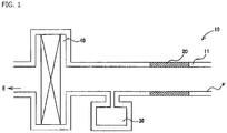
- an intake passage of an internal combustion engine is configured such that a resonator 30 is connected to an intake duct 10 formed from a pipe wall 11 of tubular shape between an intake port F and an air cleaner 40.
- the resonator 30 has a volume calculated based on Helmholtz resonance theory in order to reduce noise of a specific frequency, and by setting this volume to an appropriate value, it is made possible to reduce intake noise of the specific frequency generated in the intake passage.
- the silencing material 20 is formed on the pipe wall 11 on the intake port F side with respect to the resonator 30.
- the silencing material 20 By thus forming the silencing material 20 on the pipe wall 11 on the intake port side with respect to the resonator 30, it becomes possible to reduce intake noise more effectively. Note that the resonator 30 may not be provided as long as the intake noise can be sufficiently reduced only by the silencing material 20.
- the intake duct 10 according to the present embodiment will be described with reference to FIGS. 2 and 3 .
- the intake duct 10 according to the present embodiment has a pipe wall 11 formed of resin into a tubular shape. Further, since a part of the pipe wall 11 is formed from a lattice-shaped frame 12, a plurality of open portions 13 are formed in the pipe wall 11.
- the silencing material 20 is insert-molded so as to cover the open portions 13 so that the open portions 13 are closed.
- the intake duct 10 is formed by insert-molding the silencing material 20, the synthetic resin material has not soaked into between the fibers of the silencing material 20, and therefore the silencing material 20, and the pipe wall 11 and the lattice-shaped frame 12 are joined to each other not as a result of the synthetic resin material being impregnated and solidified between the fibers of the silencing material 20, but by an anchor effect on the surface of the silencing material 20.
- the silencing material 20 may be wound around the outer periphery of the intake duct 10 so as to cover the open portions 13.
- the pipe wall 11 in which the silencing material 20 is insert-molded forms the intake duct 10 by butting and joining half-round ducts 10a, 10a together.
- forming the pipe wall 11 from the half-round ducts 10a will make it possible to insert-mold the silencing material 20 on the pipe wall 11 with ease.
- an engine-side duct 14 and an intake-side duct 15 are respectively joined to ends of the half-round duct 10a in the ventilation direction to form a single intake duct 10.
- the joining method general methods used for resin molding such as vibration welding, hot plate welding, and ultrasonic welding, as well as bonding by adhesive, fastening by bolt, fitting of each half-round duct, a hollow product injection molding method (DSI: Die Slide Injection method) and the like can be applied.
- DSI Die Slide Injection method
- the number of the open portions 13 and an opening area thereof can be changed as appropriate in consideration of the intake noise attenuating ability of the silencing material 20 to be used.
- the silencing material 20 is insert-molded so as to be flush with the inner peripheral surface of the pipe wall 11, the inner peripheral surface of the pipe wall 11 can be formed to be flat allowing smooth flow of the fluid passing through the inside of the intake duct.
- the silencing material 20 includes a skin layer 21 formed from a non-woven fabric impregnated with thermosetting resin, and an air-permeability adjustment layer 22 formed from stretchable paper material having a large number of irregularities formed on its surface.
- the skin layers 21 are respectively disposed on the outer surfaces of the front and back faces of the silencing material 20, and are laminated so as to sandwich the air-permeability adjustment layer 22.
- nonwoven fabrics having, as a base material, various fibers such as aramid fiber, imide fiber, polyvinyl chloride fiber, phenol fiber, rayon fiber, polyester fiber, polypropylene fiber, polyamide fiber, acrylic fiber, carbon fiber, glass fiber, alumina fiber (ceramic fiber), boron fiber, novoloid fiber, fluorine fiber, and metal fibers can be used.
- various fibers such as aramid fiber, imide fiber, polyvinyl chloride fiber, phenol fiber, rayon fiber, polyester fiber, polypropylene fiber, polyamide fiber, acrylic fiber, carbon fiber, glass fiber, alumina fiber (ceramic fiber), boron fiber, novoloid fiber, fluorine fiber, and metal fibers can be used.
- thermosetting resin to be impregnated into the nonwoven fabric for example, urethane resin, melamine resin, thermosetting acrylic resin, particularly thermosetting acrylic resin that forms an ester bond by heating and cures, urea resin, phenol resin, epoxy resin, thermosetting polyester, or the like can be used.
- the air-permeability adjustment layer 22 is formed from stretchable paper material as described above.
- the air-permeability adjustment layer 22 is laminated such that a first air-permeability adjustment layer 22a and a second air-permeability adjustment layer 22b having different airflow resistance are located adjacent to each other. It is preferable to configure such that the airflow resistance of the first air-permeability adjustment layer 22a is larger than the airflow resistance of the second air-permeability adjustment layer 22b. Further, any of the first air-permeability adjustment layer 22a or the second air-permeability adjustment layer 22b may be disposed on the outer surface side of the intake duct 10.
- first air-permeability adjustment layer 22a and the second air-permeability adjustment layer 22b are bonded to each other via an adhesive 23.
- adhesives such as acrylic resin-based adhesives, urethane resin-based adhesives, epoxy resin-based adhesives, vinyl chloride resin solvent-based adhesives, chloroprene rubber-based adhesives, cyanoacrylate-based adhesives, silicone-based adhesives, modified silicone-based adhesives, and resorcinol-based adhesives can be used.
- creped paper having crepe-like wrinkles (wrinkle-like irregularities) formed on its surface As the stretchable paper material used for the first air-permeability adjustment layer 22a and the second air-permeability adjustment layer 22b, creped paper having crepe-like wrinkles (wrinkle-like irregularities) formed on its surface, embossed paper having a large number of protrusions formed on its surface, and embossed and creped paper having crepe-like wrinkles and a large number of protrusions formed on its surface are used.
- the pulp used in the stretchable paper material include hardwood wood pulp, softwood wood pulp, hemp pulp, kenaf pulp, bamboo pulp, esbalt pulp, bagasse pulp, and reed pulp.
- a synthetic resin may be admixed in an amount of about 1 to 50%.
- the silencing material 20 is integrally formed by laminating the air-permeability adjustment layer 22 with the skin layers 21 such that the outer surfaces of the air-permeability adjustment layer 22 are sandwiched between the skin layers 21, and thereafter hot pressing and hot-plate welding them together. Note that an adhesive may be interposed as needed between the skin layer 21 and the air-permeability adjustment layer 22.
- acrylic resin-based adhesives as in the above described adhesion between the first air-permeability adjustment layer 22a and the second air-permeability adjustment layer 22b, acrylic resin-based adhesives, urethane resin-based adhesives, epoxy resin-based adhesives, vinyl chloride resin solvent-based adhesives, chloroprene rubber-based adhesives, cyanoacrylate-based adhesives, silicone-based adhesives, modified silicone-based adhesives, and resorcinol-based adhesives can be used.
- the silencing material 20 according to the present embodiment is adjusted to have a thickness of 1 to 3 mm after hot pressing, and an airflow resistance of 0.6 to 2.2 kPa ⁇ s/m.
- the silencing material 20 since the silencing material 20 according to the present embodiment includes the skin layer 21 and the air-permeability adjustment layer 22 which is capable of setting finer airflow resistance, for adjusting an overall airflow resistance, it is possible to provide a silencing material that ensures intake-noise attenuation effect equivalent to that of a conventional art and that can be more easily manufactured.
- FIG. 5 is a graph showing sound reduction measured on an intake duct incorporating a conventional silencing material having a five-layer structure and an intake duct incorporating a silencing material having a four-layer structure according to the present embodiment. Comparison was made regarding the sound reduction for each frequency among examples, in which Example 1 used a silencing material in which the airflow resistance of the first air-permeability adjustment layer was set to 0.5 kPa ⁇ s/m and the airflow resistance of the second air-permeability adjustment layer to 0.3 kPa ⁇ s/m; Example 2 used a silencing material in which the airflow resistance of the first air-permeability adjustment layer was set to 0.3 kPa ⁇ s/m and the airflow resistance of the second air-permeability adjustment layer to 0.5 kPa ⁇ s/m; and Comparative Example used a silencing material having a five-layer structure in which an intermediate layer was sandwiched between the air-permeability adjustment layers as in a conventional silencing material.
- the silencing material 20 incorporated in the intake duct 10 according to the present embodiment has the air-permeability adjustment layer 22 in which the air-permeability adjustment layers having different airflow resistance are adjacently laminated, there will be no difficulty in controlling the amount of adhesive used when bonding an intermediate layer with the air-permeability adjustment layer to laminate them as in a conventional five-layer structure in which the intermediate layer is provided between the air-permeability adjustment layers. Therefore, it is possible to provide an intake duct including a sound absorbing material that ensures intake-noise attenuation effect equivalent to that of a conventional one and that is more easily manufactured.
- the intake duct 10 has been described on an example in which open portions 13 are formed by forming the pipe wall 11 from a lattice-shaped frame 12, the pipe wall 11 may be formed with a plurality of open portions as in a punching metal, or the pipe wall 11 may be formed from a mesh-like member.
- the intake duct 10 according to the present embodiment has been described on an intake duct 10 that introduces the outside air into an internal combustion engine
- the intake duct according to the present invention will not be limited thereto and can also be applied to an intake duct that introduces outside air for cooling an alternative power engine such as a fuel cell or a storage battery mounted on a vehicle body.
- the intake noise which is made up of rotation noise and wind noise of the fan for introducing the outside air, has a higher frequency than that of the intake noise generated from the internal combustion engine.
- the silencing material 20 is applied only to a straight portion of the pipe wall 11
- the silencing material 20 can also be applied to a curved portion of the intake duct 10. It is apparent from the description of the claims that embodiments to which such alterations or improvements are made can be included in the technical scope of the present invention.
- 10 Intake duct
- 10a Half-round duct
- 11 Pipe wall
- 12 Frame
- 13 Open portion
- 14 Engine-side duct
- 15 Intake-side duct
- 20 Silencing material
- 21 Skin layer
- 22 Air-permeability adjustment layer
- 22a First air-permeability adjustment layer
- 22b Second air-permeability adjustment layer
- 23 Adhesive
- 30 Resonator
- 40 Air cleaner
- E Internal combustion engine
- F Intake port.
Landscapes
- Engineering & Computer Science (AREA)
- Mechanical Engineering (AREA)
- Chemical & Material Sciences (AREA)
- Combustion & Propulsion (AREA)
- General Engineering & Computer Science (AREA)
- Manufacturing & Machinery (AREA)
- Textile Engineering (AREA)
- Duct Arrangements (AREA)
Abstract
Provided is an intake duct including a silencing material that ensures intake-noise attenuation effect equivalent to that of a conventional one and that can be more easily manufactured. In an intake duct for introducing outside air into an internal combustion engine or an alternative power engine, the intake duct including a pipe wall formed of resin into a tubular shape, the pipe wall includes a silencing material that silences noise propagating in the intake duct, and the silencing material includes a skin layer formed from a non-woven fabric impregnated with thermosetting resin, the skin layer being disposed on an outer surface of each of front and back faces of the silencing material, and an air-permeability adjustment layer in which two or more layers of stretchable paper material are adjacently laminated, the stretchable paper material having a large number of irregularities formed on its surface between the skin layers.
Description
- The present invention relates to an intake duct, particularly to an intake duct that reduces intake sound generated when outside air is introduced into an internal combustion engine or an alternative power engine.
- Conventionally, in order to reduce intake noise generated in an intake system when outside air is introduced into an internal combustion engine such as a gasoline engine or an alternative power engine such as a fuel cell or a storage battery, it is known to provide a resonator in the intake passage to reduce noise at a specific frequency calculated based on Helmholtz resonance theory or the like, as well as to adopt various intake ducts that reduce intake noise.
- The intake duct described in Japanese Patent Publication No.
5934709 - Since the intake duct thus configured according to Japanese Patent Publication No.
5934709 - However, according to the configuration of the conventional intake duct described above, the silencing material includes a pair of skin layers disposed on the outer surfaces, and the skin layers include a pair of air-permeability adjustment layers having an intermediate layer sandwiched therebetween. Therefore, problems existed in that the intake duct has a complicated structure which is at least a five-layer structure as a whole, and that it is difficult to control the amount of adhesive used when bonding the intermediate layer with the air-permeability adjustment layer to laminate them together.
- Accordingly, the present invention has been made in view of the above described problems, and a main object of the present invention is to provide an intake duct including a silencing material that ensures intake-noise attenuation effect equivalent to that of conventional art and that can be more easily manufactured.
- The intake duct according to the present invention is an intake duct for introducing outside air into an internal combustion engine or an alternative power engine, the intake duct including a pipe wall formed of resin into a tubular shape, wherein the pipe wall includes a silencing material that silences noise propagating in the intake duct, and the silencing material includes a skin layer formed from a non-woven fabric impregnated with thermosetting resin, the skin layer being disposed on an outer surface of each of front and back faces of the silencing material, and an air-permeability adjustment layer in which two or more layers of stretchable paper material are adjacently laminated, the stretchable paper material having a large number of irregularities formed on its surface.
- Further, in the intake duct according to the present invention, preferably, the air-permeability adjustment layer includes a first air-permeability adjustment layer and a second air-permeability adjustment layer having airflow resistance different from that of the first air-permeability adjustment layer.
- Further, in the intake duct according to the present invention, preferably, the first air-permeability adjustment layer and the second air-permeability adjustment layer are laminated by being bonded together with an adhesive.
- The above described summary of the invention does not enumerate all the necessary features of the present invention, and any subcombination of these feature groups can also be an invention.
- According to the intake duct of the present invention, since the silencing material provided on the pipe wall includes the skin layer which is disposed on the outer surface of each of front and back faces, and which is formed from a non-woven fabric impregnated with thermosetting resin, and an air-permeability adjustment layer in which two or more layers of stretchable paper material having a large number of irregularities formed on its surface are adjacently laminated between the skin layers, and thus the intermediate layer is abolished, it is made possible to eliminate a step of controlling an adhesive associated with bonding of the intermediate layer, thereby enabling easier manufacturing of the silencing material.
- Further, according to the intake duct of the present invention, since the air-permeability adjustment layer constituting the silencing material is provided with the first air-permeability adjustment layer and the second air-permeability adjustment layer having mutually different airflow resistance, it is possible to ensure intake-noise attenuation effect equivalent to that of the silencing material used in a conventional intake duct.
-
-
FIG. 1 is a schematic diagram showing an intake passage of an internal combustion engine; -
FIG. 2 is a perspective view of an intake duct according to the present embodiment; -
FIG. 3 is a perspective view of a half-round duct constituting the intake duct according to the present embodiment; -
FIG. 4 is a sectional diagram to illustrate the structure of a silencing material; and -
FIG. 5 is a graph showing sound reduction measured in a wide frequency band on a silencing material used in the intake duct of the present embodiment, and a conventional silencing material. - Hereinafter, preferred embodiments for carrying out the present invention will be described with reference to the drawings. It should be noted that the following embodiments do not limit the invention according to each claim, and that all the combinations of the features described in the embodiments are not necessarily essential to the solution of the invention.
-
FIG. 1 is a schematic diagram showing an intake passage of an internal combustion engine;FIG. 2 is a perspective view of an intake duct according to the present embodiment;FIG. 3 is a perspective view of a half-round duct constituting the intake duct according to the present embodiment;FIG. 4 is a sectional diagram to illustrate the structure of a silencing material; andFIG. 5 is a graph showing sound reduction measured in a wide frequency band on a silencing material used in the intake duct of the present embodiment, and a conventional silencing material. - As shown in
FIG. 1 , an intake passage of an internal combustion engine is configured such that aresonator 30 is connected to anintake duct 10 formed from apipe wall 11 of tubular shape between an intake port F and anair cleaner 40. Theresonator 30 has a volume calculated based on Helmholtz resonance theory in order to reduce noise of a specific frequency, and by setting this volume to an appropriate value, it is made possible to reduce intake noise of the specific frequency generated in the intake passage. Further, in theintake duct 10 according to the present embodiment, as shown inFIG. 1 , thesilencing material 20 is formed on thepipe wall 11 on the intake port F side with respect to theresonator 30. By thus forming the silencingmaterial 20 on thepipe wall 11 on the intake port side with respect to theresonator 30, it becomes possible to reduce intake noise more effectively. Note that theresonator 30 may not be provided as long as the intake noise can be sufficiently reduced only by thesilencing material 20. - Next, the
intake duct 10 according to the present embodiment will be described with reference toFIGS. 2 and3 . As shown inFIG. 2 , theintake duct 10 according to the present embodiment has apipe wall 11 formed of resin into a tubular shape. Further, since a part of thepipe wall 11 is formed from a lattice-shaped frame 12, a plurality ofopen portions 13 are formed in thepipe wall 11. Thesilencing material 20 is insert-molded so as to cover theopen portions 13 so that theopen portions 13 are closed. While theintake duct 10 according to the present embodiment is formed by insert-molding the silencingmaterial 20, the synthetic resin material has not soaked into between the fibers of thesilencing material 20, and therefore thesilencing material 20, and thepipe wall 11 and the lattice-shaped frame 12 are joined to each other not as a result of the synthetic resin material being impregnated and solidified between the fibers of the silencingmaterial 20, but by an anchor effect on the surface of the silencingmaterial 20. Note that although, in the present embodiment, a case in which thesilencing material 20 is insert-molded on thepipe wall 11 has been described, the silencingmaterial 20 may be wound around the outer periphery of theintake duct 10 so as to cover theopen portions 13. - As shown in
FIG. 3 , thepipe wall 11 in which the silencingmaterial 20 is insert-molded forms theintake duct 10 by butting and joining half-round ducts pipe wall 11 from the half-round ducts 10a will make it possible to insert-mold the silencingmaterial 20 on thepipe wall 11 with ease. In addition, as shown inFIG. 2 , an engine-side duct 14 and an intake-side duct 15 are respectively joined to ends of the half-round duct 10a in the ventilation direction to form asingle intake duct 10. As the joining method, general methods used for resin molding such as vibration welding, hot plate welding, and ultrasonic welding, as well as bonding by adhesive, fastening by bolt, fitting of each half-round duct, a hollow product injection molding method (DSI: Die Slide Injection method) and the like can be applied. Note that the number of theopen portions 13 and an opening area thereof can be changed as appropriate in consideration of the intake noise attenuating ability of the silencingmaterial 20 to be used. Furthermore, since, as shown inFIG. 3 , thesilencing material 20 is insert-molded so as to be flush with the inner peripheral surface of thepipe wall 11, the inner peripheral surface of thepipe wall 11 can be formed to be flat allowing smooth flow of the fluid passing through the inside of the intake duct. - Next, with reference to
FIG. 4 , the configuration of thesilencing material 20 will be described. Thesilencing material 20 includes askin layer 21 formed from a non-woven fabric impregnated with thermosetting resin, and an air-permeability adjustment layer 22 formed from stretchable paper material having a large number of irregularities formed on its surface. Theskin layers 21 are respectively disposed on the outer surfaces of the front and back faces of thesilencing material 20, and are laminated so as to sandwich the air-permeability adjustment layer 22. - As the nonwoven fabric used for the
skin layer 21, nonwoven fabrics having, as a base material, various fibers such as aramid fiber, imide fiber, polyvinyl chloride fiber, phenol fiber, rayon fiber, polyester fiber, polypropylene fiber, polyamide fiber, acrylic fiber, carbon fiber, glass fiber, alumina fiber (ceramic fiber), boron fiber, novoloid fiber, fluorine fiber, and metal fibers can be used. - Further, as the thermosetting resin to be impregnated into the nonwoven fabric, for example, urethane resin, melamine resin, thermosetting acrylic resin, particularly thermosetting acrylic resin that forms an ester bond by heating and cures, urea resin, phenol resin, epoxy resin, thermosetting polyester, or the like can be used.
- Next, the air-
permeability adjustment layer 22 will be described. The air-permeability adjustment layer 22 is formed from stretchable paper material as described above. The air-permeability adjustment layer 22 is laminated such that a first air-permeability adjustment layer 22a and a second air-permeability adjustment layer 22b having different airflow resistance are located adjacent to each other. It is preferable to configure such that the airflow resistance of the first air-permeability adjustment layer 22a is larger than the airflow resistance of the second air-permeability adjustment layer 22b. Further, any of the first air-permeability adjustment layer 22a or the second air-permeability adjustment layer 22b may be disposed on the outer surface side of theintake duct 10. - In this way, by laminating a plurality of air-permeability adjustment layers having different airflow resistance adjacent to each other, it is possible to arbitrarily set the airflow resistance of the air-
permeability adjustment layer 22 as a whole, thus allowing more precise setting of airflow resistance. - Further, it is preferable that the first air-
permeability adjustment layer 22a and the second air-permeability adjustment layer 22b are bonded to each other via an adhesive 23. Note that, as the adhesive 23, adhesives such as acrylic resin-based adhesives, urethane resin-based adhesives, epoxy resin-based adhesives, vinyl chloride resin solvent-based adhesives, chloroprene rubber-based adhesives, cyanoacrylate-based adhesives, silicone-based adhesives, modified silicone-based adhesives, and resorcinol-based adhesives can be used. - As the stretchable paper material used for the first air-
permeability adjustment layer 22a and the second air-permeability adjustment layer 22b, creped paper having crepe-like wrinkles (wrinkle-like irregularities) formed on its surface, embossed paper having a large number of protrusions formed on its surface, and embossed and creped paper having crepe-like wrinkles and a large number of protrusions formed on its surface are used. Examples of the pulp used in the stretchable paper material include hardwood wood pulp, softwood wood pulp, hemp pulp, kenaf pulp, bamboo pulp, esbalt pulp, bagasse pulp, and reed pulp. In addition to these wood pulp and natural pulp such as non-wood pulp, a synthetic resin may be admixed in an amount of about 1 to 50%. - Next, the structure of the
silencing material 20 according to the present embodiment will be described. As shown inFIG. 4 , thesilencing material 20 is integrally formed by laminating the air-permeability adjustment layer 22 with theskin layers 21 such that the outer surfaces of the air-permeability adjustment layer 22 are sandwiched between theskin layers 21, and thereafter hot pressing and hot-plate welding them together. Note that an adhesive may be interposed as needed between theskin layer 21 and the air-permeability adjustment layer 22. As the adhesive, as in the above described adhesion between the first air-permeability adjustment layer 22a and the second air-permeability adjustment layer 22b, acrylic resin-based adhesives, urethane resin-based adhesives, epoxy resin-based adhesives, vinyl chloride resin solvent-based adhesives, chloroprene rubber-based adhesives, cyanoacrylate-based adhesives, silicone-based adhesives, modified silicone-based adhesives, and resorcinol-based adhesives can be used. - Note that the
silencing material 20 according to the present embodiment is adjusted to have a thickness of 1 to 3 mm after hot pressing, and an airflow resistance of 0.6 to 2.2 kPa·s/m. - Thus, since the silencing
material 20 according to the present embodiment includes theskin layer 21 and the air-permeability adjustment layer 22 which is capable of setting finer airflow resistance, for adjusting an overall airflow resistance, it is possible to provide a silencing material that ensures intake-noise attenuation effect equivalent to that of a conventional art and that can be more easily manufactured. -
FIG. 5 is a graph showing sound reduction measured on an intake duct incorporating a conventional silencing material having a five-layer structure and an intake duct incorporating a silencing material having a four-layer structure according to the present embodiment. Comparison was made regarding the sound reduction for each frequency among examples, in which Example 1 used a silencing material in which the airflow resistance of the first air-permeability adjustment layer was set to 0.5 kPa·s/m and the airflow resistance of the second air-permeability adjustment layer to 0.3 kPa·s/m; Example 2 used a silencing material in which the airflow resistance of the first air-permeability adjustment layer was set to 0.3 kPa·s/m and the airflow resistance of the second air-permeability adjustment layer to 0.5 kPa·s/m; and Comparative Example used a silencing material having a five-layer structure in which an intermediate layer was sandwiched between the air-permeability adjustment layers as in a conventional silencing material. - As shown in
FIG. 5 , it was confirmed that Examples 1 and 2 exhibited equivalent silencing effect to that of Comparative Example in all frequency bands. - In this way, since the silencing
material 20 incorporated in theintake duct 10 according to the present embodiment has the air-permeability adjustment layer 22 in which the air-permeability adjustment layers having different airflow resistance are adjacently laminated, there will be no difficulty in controlling the amount of adhesive used when bonding an intermediate layer with the air-permeability adjustment layer to laminate them as in a conventional five-layer structure in which the intermediate layer is provided between the air-permeability adjustment layers. Therefore, it is possible to provide an intake duct including a sound absorbing material that ensures intake-noise attenuation effect equivalent to that of a conventional one and that is more easily manufactured. - Note that although the
intake duct 10 according to the present embodiment has been described on an example in which openportions 13 are formed by forming thepipe wall 11 from a lattice-shapedframe 12, thepipe wall 11 may be formed with a plurality of open portions as in a punching metal, or thepipe wall 11 may be formed from a mesh-like member. - Further, although the
intake duct 10 according to the present embodiment has been described on anintake duct 10 that introduces the outside air into an internal combustion engine, the intake duct according to the present invention will not be limited thereto and can also be applied to an intake duct that introduces outside air for cooling an alternative power engine such as a fuel cell or a storage battery mounted on a vehicle body. In this case, the intake noise, which is made up of rotation noise and wind noise of the fan for introducing the outside air, has a higher frequency than that of the intake noise generated from the internal combustion engine. - Further, in the
intake duct 10 according to the present embodiment, although description has been made on a case where the silencingmaterial 20 is applied only to a straight portion of thepipe wall 11, the silencingmaterial 20 can also be applied to a curved portion of theintake duct 10. It is apparent from the description of the claims that embodiments to which such alterations or improvements are made can be included in the technical scope of the present invention. - 10: Intake duct, 10a: Half-round duct, 11: Pipe wall, 12: Frame, 13: Open portion, 14: Engine-side duct, 15: Intake-side duct,20: Silencing material, 21: Skin layer, 22: Air-permeability adjustment layer, 22a: First air-permeability adjustment layer, 22b: Second air-permeability adjustment layer, 23: Adhesive, 30: Resonator, 40: Air cleaner, E: Internal combustion engine, F: Intake port.
- The invention may be embodied in other specific forms without departing from the spirit or essential characteristics thereof. The present embodiments are therefore to be considered in all respects as illustrative and not restrictive, the scope of the invention being indicated by the appended claims rather than by the foregoing description and all changes which come within the meaning and range of equivalency of the claims are therefore intended to be embraced therein.
- The entire disclosure of Japanese Patent Application No.
2019-174683 filed on September 25, 2019
Claims (3)
- An intake duct for introducing outside air into an internal combustion engine or an alternative power engine, the intake duct comprising a pipe wall formed of resin into a tubular shape, wherein
the pipe wall comprises a silencing material that silences noise propagating in the intake duct, and
the silencing material comprises a skin layer formed from a non-woven fabric impregnated with thermosetting resin, the skin layer being disposed on an outer surface of each of front and back faces of the silencing material, and an air-permeability adjustment layer in which two or more layers of stretchable paper material are adjacently laminated, the stretchable paper material having a large number of irregularities formed on its surface between the skin layers. - The intake duct according to claim 1, wherein
the air-permeability adjustment layer comprises a first air-permeability adjustment layer and a second air-permeability adjustment layer having airflow resistance different from that of the first air-permeability adjustment layer. - The intake duct according to claim 2, wherein
the first air-permeability adjustment layer and the second air-permeability adjustment layer are laminated by being bonded together with an adhesive.
Applications Claiming Priority (1)
| Application Number | Priority Date | Filing Date | Title |
|---|---|---|---|
| JP2019174683A JP2021050672A (en) | 2019-09-25 | 2019-09-25 | Suction duct |
Publications (1)
| Publication Number | Publication Date |
|---|---|
| EP3798440A1 true EP3798440A1 (en) | 2021-03-31 |
Family
ID=72355883
Family Applications (1)
| Application Number | Title | Priority Date | Filing Date |
|---|---|---|---|
| EP20194324.8A Withdrawn EP3798440A1 (en) | 2019-09-25 | 2020-09-03 | Intake duct |
Country Status (2)
| Country | Link |
|---|---|
| EP (1) | EP3798440A1 (en) |
| JP (1) | JP2021050672A (en) |
Citations (6)
| Publication number | Priority date | Publication date | Assignee | Title |
|---|---|---|---|---|
| GB957709A (en) * | 1959-02-16 | 1964-05-13 | Thermotank Plastic Engineering | Improvements in or relating to tubes and method of production thereof |
| JPS5934709B2 (en) | 1974-08-31 | 1984-08-24 | バイエル・アクチエンゲゼルシヤフト | Method for producing chlorinated imidazole derivatives |
| US20090293832A1 (en) * | 2008-06-03 | 2009-12-03 | Roki Co., Ltd. | Intake duct |
| EP2236286A1 (en) * | 2008-02-14 | 2010-10-06 | Nagoya Oilchemical Co., Ltd. | Sound absorbing skin material and sound absorbing material utilizing the same |
| EP2754881A1 (en) * | 2011-09-05 | 2014-07-16 | Roki Co., Ltd. | Aspiration duct |
| JP2019174683A (en) | 2018-03-29 | 2019-10-10 | 株式会社 ジーアイシー | Surveillance infrared camera device |
-
2019
- 2019-09-25 JP JP2019174683A patent/JP2021050672A/en active Pending
-
2020
- 2020-09-03 EP EP20194324.8A patent/EP3798440A1/en not_active Withdrawn
Patent Citations (6)
| Publication number | Priority date | Publication date | Assignee | Title |
|---|---|---|---|---|
| GB957709A (en) * | 1959-02-16 | 1964-05-13 | Thermotank Plastic Engineering | Improvements in or relating to tubes and method of production thereof |
| JPS5934709B2 (en) | 1974-08-31 | 1984-08-24 | バイエル・アクチエンゲゼルシヤフト | Method for producing chlorinated imidazole derivatives |
| EP2236286A1 (en) * | 2008-02-14 | 2010-10-06 | Nagoya Oilchemical Co., Ltd. | Sound absorbing skin material and sound absorbing material utilizing the same |
| US20090293832A1 (en) * | 2008-06-03 | 2009-12-03 | Roki Co., Ltd. | Intake duct |
| EP2754881A1 (en) * | 2011-09-05 | 2014-07-16 | Roki Co., Ltd. | Aspiration duct |
| JP2019174683A (en) | 2018-03-29 | 2019-10-10 | 株式会社 ジーアイシー | Surveillance infrared camera device |
Also Published As
| Publication number | Publication date |
|---|---|
| JP2021050672A (en) | 2021-04-01 |
Similar Documents
| Publication | Publication Date | Title |
|---|---|---|
| JP5934709B2 (en) | Air intake duct | |
| US8820477B1 (en) | Acoustic panel | |
| EP2669888B1 (en) | Process for production of a sound-proof material | |
| KR100674125B1 (en) | Intake duct | |
| EP2998163B1 (en) | Engine cover | |
| JP4767209B2 (en) | Soundproof cover | |
| CN101827702B (en) | Cellular-core structure for an acoustic panel | |
| JP7326649B2 (en) | automotive sound insulation | |
| KR20110031136A (en) | Soundproof cover, manufacturing method and soundproofing method | |
| JP2005523196A (en) | Density gradient pad material and manufacturing method thereof | |
| US20180340499A1 (en) | Intake passage component for internal combustion engine | |
| KR20140067344A (en) | Composite sound absorbing materials for automobile and manufacture method of the same | |
| US20040226772A1 (en) | Air intake apparatus | |
| JP6754724B2 (en) | Soundproof coating and engine unit | |
| JP2023009125A (en) | deck board | |
| CN114730559A (en) | Sound attenuation panel and method for manufacturing same | |
| WO2019004153A1 (en) | Soundproof covering material and engine unit | |
| US11325323B2 (en) | Method for producing an acoustically resistive structure, acoustically resistive structure thus obtained, and sound-absorption panel comprising said acoustically resistive structure | |
| EP3798440A1 (en) | Intake duct | |
| KR101447626B1 (en) | Carpet capable absorbing and isolating function of sounds for vehicle | |
| JP3710775B2 (en) | Sound absorbing material and air blower with sound absorbing device using the sound absorbing material | |
| KR101497379B1 (en) | Insulation for vehicle | |
| CN212423282U (en) | Engine compartment cover and automobile | |
| KR200387474Y1 (en) | Suction Duct | |
| KR20040002979A (en) | Under carpet heat shield and floor pan insulator |
Legal Events
| Date | Code | Title | Description |
|---|---|---|---|
| PUAI | Public reference made under article 153(3) epc to a published international application that has entered the european phase |
Free format text: ORIGINAL CODE: 0009012 |
|
| STAA | Information on the status of an ep patent application or granted ep patent |
Free format text: STATUS: THE APPLICATION HAS BEEN PUBLISHED |
|
| AK | Designated contracting states |
Kind code of ref document: A1 Designated state(s): AL AT BE BG CH CY CZ DE DK EE ES FI FR GB GR HR HU IE IS IT LI LT LU LV MC MK MT NL NO PL PT RO RS SE SI SK SM TR |
|
| AX | Request for extension of the european patent |
Extension state: BA ME |
|
| STAA | Information on the status of an ep patent application or granted ep patent |
Free format text: STATUS: THE APPLICATION IS DEEMED TO BE WITHDRAWN |
|
| 18D | Application deemed to be withdrawn |
Effective date: 20211001 |