EP3797985A1 - Method for manufacturing bonded body of different materials and bonded structure of different materials - Google Patents
Method for manufacturing bonded body of different materials and bonded structure of different materials Download PDFInfo
- Publication number
- EP3797985A1 EP3797985A1 EP19865390.9A EP19865390A EP3797985A1 EP 3797985 A1 EP3797985 A1 EP 3797985A1 EP 19865390 A EP19865390 A EP 19865390A EP 3797985 A1 EP3797985 A1 EP 3797985A1
- Authority
- EP
- European Patent Office
- Prior art keywords
- resin layer
- metal substrate
- laser
- different materials
- etched
- Prior art date
- Legal status (The legal status is an assumption and is not a legal conclusion. Google has not performed a legal analysis and makes no representation as to the accuracy of the status listed.)
- Pending
Links
Images


Classifications
-
- B—PERFORMING OPERATIONS; TRANSPORTING
- B29—WORKING OF PLASTICS; WORKING OF SUBSTANCES IN A PLASTIC STATE IN GENERAL
- B29C—SHAPING OR JOINING OF PLASTICS; SHAPING OF MATERIAL IN A PLASTIC STATE, NOT OTHERWISE PROVIDED FOR; AFTER-TREATMENT OF THE SHAPED PRODUCTS, e.g. REPAIRING
- B29C65/00—Joining or sealing of preformed parts, e.g. welding of plastics materials; Apparatus therefor
- B29C65/02—Joining or sealing of preformed parts, e.g. welding of plastics materials; Apparatus therefor by heating, with or without pressure
- B29C65/14—Joining or sealing of preformed parts, e.g. welding of plastics materials; Apparatus therefor by heating, with or without pressure using wave energy, i.e. electromagnetic radiation, or particle radiation
- B29C65/16—Laser beams
- B29C65/1629—Laser beams characterised by the way of heating the interface
- B29C65/1635—Laser beams characterised by the way of heating the interface at least passing through one of the parts to be joined, i.e. laser transmission welding
-
- B—PERFORMING OPERATIONS; TRANSPORTING
- B23—MACHINE TOOLS; METAL-WORKING NOT OTHERWISE PROVIDED FOR
- B23K—SOLDERING OR UNSOLDERING; WELDING; CLADDING OR PLATING BY SOLDERING OR WELDING; CUTTING BY APPLYING HEAT LOCALLY, e.g. FLAME CUTTING; WORKING BY LASER BEAM
- B23K26/00—Working by laser beam, e.g. welding, cutting or boring
- B23K26/36—Removing material
- B23K26/362—Laser etching
- B23K26/364—Laser etching for making a groove or trench, e.g. for scribing a break initiation groove
-
- B—PERFORMING OPERATIONS; TRANSPORTING
- B29—WORKING OF PLASTICS; WORKING OF SUBSTANCES IN A PLASTIC STATE IN GENERAL
- B29C—SHAPING OR JOINING OF PLASTICS; SHAPING OF MATERIAL IN A PLASTIC STATE, NOT OTHERWISE PROVIDED FOR; AFTER-TREATMENT OF THE SHAPED PRODUCTS, e.g. REPAIRING
- B29C65/00—Joining or sealing of preformed parts, e.g. welding of plastics materials; Apparatus therefor
- B29C65/02—Joining or sealing of preformed parts, e.g. welding of plastics materials; Apparatus therefor by heating, with or without pressure
- B29C65/14—Joining or sealing of preformed parts, e.g. welding of plastics materials; Apparatus therefor by heating, with or without pressure using wave energy, i.e. electromagnetic radiation, or particle radiation
- B29C65/16—Laser beams
- B29C65/1603—Laser beams characterised by the type of electromagnetic radiation
- B29C65/1612—Infrared [IR] radiation, e.g. by infrared lasers
- B29C65/1616—Near infrared radiation [NIR], e.g. by YAG lasers
-
- B—PERFORMING OPERATIONS; TRANSPORTING
- B29—WORKING OF PLASTICS; WORKING OF SUBSTANCES IN A PLASTIC STATE IN GENERAL
- B29C—SHAPING OR JOINING OF PLASTICS; SHAPING OF MATERIAL IN A PLASTIC STATE, NOT OTHERWISE PROVIDED FOR; AFTER-TREATMENT OF THE SHAPED PRODUCTS, e.g. REPAIRING
- B29C65/00—Joining or sealing of preformed parts, e.g. welding of plastics materials; Apparatus therefor
- B29C65/02—Joining or sealing of preformed parts, e.g. welding of plastics materials; Apparatus therefor by heating, with or without pressure
- B29C65/14—Joining or sealing of preformed parts, e.g. welding of plastics materials; Apparatus therefor by heating, with or without pressure using wave energy, i.e. electromagnetic radiation, or particle radiation
- B29C65/16—Laser beams
- B29C65/1629—Laser beams characterised by the way of heating the interface
- B29C65/1654—Laser beams characterised by the way of heating the interface scanning at least one of the parts to be joined
-
- B—PERFORMING OPERATIONS; TRANSPORTING
- B29—WORKING OF PLASTICS; WORKING OF SUBSTANCES IN A PLASTIC STATE IN GENERAL
- B29C—SHAPING OR JOINING OF PLASTICS; SHAPING OF MATERIAL IN A PLASTIC STATE, NOT OTHERWISE PROVIDED FOR; AFTER-TREATMENT OF THE SHAPED PRODUCTS, e.g. REPAIRING
- B29C65/00—Joining or sealing of preformed parts, e.g. welding of plastics materials; Apparatus therefor
- B29C65/02—Joining or sealing of preformed parts, e.g. welding of plastics materials; Apparatus therefor by heating, with or without pressure
- B29C65/14—Joining or sealing of preformed parts, e.g. welding of plastics materials; Apparatus therefor by heating, with or without pressure using wave energy, i.e. electromagnetic radiation, or particle radiation
- B29C65/16—Laser beams
- B29C65/1629—Laser beams characterised by the way of heating the interface
- B29C65/1674—Laser beams characterised by the way of heating the interface making use of laser diodes
-
- B—PERFORMING OPERATIONS; TRANSPORTING
- B29—WORKING OF PLASTICS; WORKING OF SUBSTANCES IN A PLASTIC STATE IN GENERAL
- B29C—SHAPING OR JOINING OF PLASTICS; SHAPING OF MATERIAL IN A PLASTIC STATE, NOT OTHERWISE PROVIDED FOR; AFTER-TREATMENT OF THE SHAPED PRODUCTS, e.g. REPAIRING
- B29C65/00—Joining or sealing of preformed parts, e.g. welding of plastics materials; Apparatus therefor
- B29C65/82—Testing the joint
- B29C65/8207—Testing the joint by mechanical methods
- B29C65/8215—Tensile tests
-
- B—PERFORMING OPERATIONS; TRANSPORTING
- B29—WORKING OF PLASTICS; WORKING OF SUBSTANCES IN A PLASTIC STATE IN GENERAL
- B29C—SHAPING OR JOINING OF PLASTICS; SHAPING OF MATERIAL IN A PLASTIC STATE, NOT OTHERWISE PROVIDED FOR; AFTER-TREATMENT OF THE SHAPED PRODUCTS, e.g. REPAIRING
- B29C65/00—Joining or sealing of preformed parts, e.g. welding of plastics materials; Apparatus therefor
- B29C65/82—Testing the joint
- B29C65/8253—Testing the joint by the use of waves or particle radiation, e.g. visual examination, scanning electron microscopy, or X-rays
-
- B—PERFORMING OPERATIONS; TRANSPORTING
- B29—WORKING OF PLASTICS; WORKING OF SUBSTANCES IN A PLASTIC STATE IN GENERAL
- B29C—SHAPING OR JOINING OF PLASTICS; SHAPING OF MATERIAL IN A PLASTIC STATE, NOT OTHERWISE PROVIDED FOR; AFTER-TREATMENT OF THE SHAPED PRODUCTS, e.g. REPAIRING
- B29C66/00—General aspects of processes or apparatus for joining preformed parts
- B29C66/01—General aspects dealing with the joint area or with the area to be joined
- B29C66/02—Preparation of the material, in the area to be joined, prior to joining or welding
- B29C66/024—Thermal pre-treatments
- B29C66/0246—Cutting or perforating, e.g. burning away by using a laser or using hot air
-
- B—PERFORMING OPERATIONS; TRANSPORTING
- B29—WORKING OF PLASTICS; WORKING OF SUBSTANCES IN A PLASTIC STATE IN GENERAL
- B29C—SHAPING OR JOINING OF PLASTICS; SHAPING OF MATERIAL IN A PLASTIC STATE, NOT OTHERWISE PROVIDED FOR; AFTER-TREATMENT OF THE SHAPED PRODUCTS, e.g. REPAIRING
- B29C66/00—General aspects of processes or apparatus for joining preformed parts
- B29C66/01—General aspects dealing with the joint area or with the area to be joined
- B29C66/05—Particular design of joint configurations
- B29C66/10—Particular design of joint configurations particular design of the joint cross-sections
- B29C66/11—Joint cross-sections comprising a single joint-segment, i.e. one of the parts to be joined comprising a single joint-segment in the joint cross-section
- B29C66/112—Single lapped joints
- B29C66/1122—Single lap to lap joints, i.e. overlap joints
-
- B—PERFORMING OPERATIONS; TRANSPORTING
- B29—WORKING OF PLASTICS; WORKING OF SUBSTANCES IN A PLASTIC STATE IN GENERAL
- B29C—SHAPING OR JOINING OF PLASTICS; SHAPING OF MATERIAL IN A PLASTIC STATE, NOT OTHERWISE PROVIDED FOR; AFTER-TREATMENT OF THE SHAPED PRODUCTS, e.g. REPAIRING
- B29C66/00—General aspects of processes or apparatus for joining preformed parts
- B29C66/01—General aspects dealing with the joint area or with the area to be joined
- B29C66/05—Particular design of joint configurations
- B29C66/303—Particular design of joint configurations the joint involving an anchoring effect
- B29C66/3032—Particular design of joint configurations the joint involving an anchoring effect making use of protrusions or cavities belonging to at least one of the parts to be joined
- B29C66/30321—Particular design of joint configurations the joint involving an anchoring effect making use of protrusions or cavities belonging to at least one of the parts to be joined making use of protrusions belonging to at least one of the parts to be joined
-
- B—PERFORMING OPERATIONS; TRANSPORTING
- B29—WORKING OF PLASTICS; WORKING OF SUBSTANCES IN A PLASTIC STATE IN GENERAL
- B29C—SHAPING OR JOINING OF PLASTICS; SHAPING OF MATERIAL IN A PLASTIC STATE, NOT OTHERWISE PROVIDED FOR; AFTER-TREATMENT OF THE SHAPED PRODUCTS, e.g. REPAIRING
- B29C66/00—General aspects of processes or apparatus for joining preformed parts
- B29C66/01—General aspects dealing with the joint area or with the area to be joined
- B29C66/05—Particular design of joint configurations
- B29C66/303—Particular design of joint configurations the joint involving an anchoring effect
- B29C66/3032—Particular design of joint configurations the joint involving an anchoring effect making use of protrusions or cavities belonging to at least one of the parts to be joined
- B29C66/30325—Particular design of joint configurations the joint involving an anchoring effect making use of protrusions or cavities belonging to at least one of the parts to be joined making use of cavities belonging to at least one of the parts to be joined
-
- B—PERFORMING OPERATIONS; TRANSPORTING
- B29—WORKING OF PLASTICS; WORKING OF SUBSTANCES IN A PLASTIC STATE IN GENERAL
- B29C—SHAPING OR JOINING OF PLASTICS; SHAPING OF MATERIAL IN A PLASTIC STATE, NOT OTHERWISE PROVIDED FOR; AFTER-TREATMENT OF THE SHAPED PRODUCTS, e.g. REPAIRING
- B29C66/00—General aspects of processes or apparatus for joining preformed parts
- B29C66/40—General aspects of joining substantially flat articles, e.g. plates, sheets or web-like materials; Making flat seams in tubular or hollow articles; Joining single elements to substantially flat surfaces
- B29C66/41—Joining substantially flat articles ; Making flat seams in tubular or hollow articles
- B29C66/43—Joining a relatively small portion of the surface of said articles
-
- B—PERFORMING OPERATIONS; TRANSPORTING
- B29—WORKING OF PLASTICS; WORKING OF SUBSTANCES IN A PLASTIC STATE IN GENERAL
- B29C—SHAPING OR JOINING OF PLASTICS; SHAPING OF MATERIAL IN A PLASTIC STATE, NOT OTHERWISE PROVIDED FOR; AFTER-TREATMENT OF THE SHAPED PRODUCTS, e.g. REPAIRING
- B29C66/00—General aspects of processes or apparatus for joining preformed parts
- B29C66/70—General aspects of processes or apparatus for joining preformed parts characterised by the composition, physical properties or the structure of the material of the parts to be joined; Joining with non-plastics material
- B29C66/71—General aspects of processes or apparatus for joining preformed parts characterised by the composition, physical properties or the structure of the material of the parts to be joined; Joining with non-plastics material characterised by the composition of the plastics material of the parts to be joined
-
- B—PERFORMING OPERATIONS; TRANSPORTING
- B29—WORKING OF PLASTICS; WORKING OF SUBSTANCES IN A PLASTIC STATE IN GENERAL
- B29C—SHAPING OR JOINING OF PLASTICS; SHAPING OF MATERIAL IN A PLASTIC STATE, NOT OTHERWISE PROVIDED FOR; AFTER-TREATMENT OF THE SHAPED PRODUCTS, e.g. REPAIRING
- B29C66/00—General aspects of processes or apparatus for joining preformed parts
- B29C66/70—General aspects of processes or apparatus for joining preformed parts characterised by the composition, physical properties or the structure of the material of the parts to be joined; Joining with non-plastics material
- B29C66/72—General aspects of processes or apparatus for joining preformed parts characterised by the composition, physical properties or the structure of the material of the parts to be joined; Joining with non-plastics material characterised by the structure of the material of the parts to be joined
- B29C66/721—Fibre-reinforced materials
- B29C66/7212—Fibre-reinforced materials characterised by the composition of the fibres
-
- B—PERFORMING OPERATIONS; TRANSPORTING
- B29—WORKING OF PLASTICS; WORKING OF SUBSTANCES IN A PLASTIC STATE IN GENERAL
- B29C—SHAPING OR JOINING OF PLASTICS; SHAPING OF MATERIAL IN A PLASTIC STATE, NOT OTHERWISE PROVIDED FOR; AFTER-TREATMENT OF THE SHAPED PRODUCTS, e.g. REPAIRING
- B29C66/00—General aspects of processes or apparatus for joining preformed parts
- B29C66/70—General aspects of processes or apparatus for joining preformed parts characterised by the composition, physical properties or the structure of the material of the parts to be joined; Joining with non-plastics material
- B29C66/73—General aspects of processes or apparatus for joining preformed parts characterised by the composition, physical properties or the structure of the material of the parts to be joined; Joining with non-plastics material characterised by the intensive physical properties of the material of the parts to be joined, by the optical properties of the material of the parts to be joined, by the extensive physical properties of the parts to be joined, by the state of the material of the parts to be joined or by the material of the parts to be joined being a thermoplastic or a thermoset
- B29C66/739—General aspects of processes or apparatus for joining preformed parts characterised by the composition, physical properties or the structure of the material of the parts to be joined; Joining with non-plastics material characterised by the intensive physical properties of the material of the parts to be joined, by the optical properties of the material of the parts to be joined, by the extensive physical properties of the parts to be joined, by the state of the material of the parts to be joined or by the material of the parts to be joined being a thermoplastic or a thermoset characterised by the material of the parts to be joined being a thermoplastic or a thermoset
- B29C66/7392—General aspects of processes or apparatus for joining preformed parts characterised by the composition, physical properties or the structure of the material of the parts to be joined; Joining with non-plastics material characterised by the intensive physical properties of the material of the parts to be joined, by the optical properties of the material of the parts to be joined, by the extensive physical properties of the parts to be joined, by the state of the material of the parts to be joined or by the material of the parts to be joined being a thermoplastic or a thermoset characterised by the material of the parts to be joined being a thermoplastic or a thermoset characterised by the material of at least one of the parts being a thermoplastic
-
- B—PERFORMING OPERATIONS; TRANSPORTING
- B29—WORKING OF PLASTICS; WORKING OF SUBSTANCES IN A PLASTIC STATE IN GENERAL
- B29C—SHAPING OR JOINING OF PLASTICS; SHAPING OF MATERIAL IN A PLASTIC STATE, NOT OTHERWISE PROVIDED FOR; AFTER-TREATMENT OF THE SHAPED PRODUCTS, e.g. REPAIRING
- B29C66/00—General aspects of processes or apparatus for joining preformed parts
- B29C66/70—General aspects of processes or apparatus for joining preformed parts characterised by the composition, physical properties or the structure of the material of the parts to be joined; Joining with non-plastics material
- B29C66/74—Joining plastics material to non-plastics material
- B29C66/742—Joining plastics material to non-plastics material to metals or their alloys
-
- B—PERFORMING OPERATIONS; TRANSPORTING
- B32—LAYERED PRODUCTS
- B32B—LAYERED PRODUCTS, i.e. PRODUCTS BUILT-UP OF STRATA OF FLAT OR NON-FLAT, e.g. CELLULAR OR HONEYCOMB, FORM
- B32B15/00—Layered products comprising a layer of metal
- B32B15/04—Layered products comprising a layer of metal comprising metal as the main or only constituent of a layer, which is next to another layer of the same or of a different material
- B32B15/08—Layered products comprising a layer of metal comprising metal as the main or only constituent of a layer, which is next to another layer of the same or of a different material of synthetic resin
-
- B—PERFORMING OPERATIONS; TRANSPORTING
- B32—LAYERED PRODUCTS
- B32B—LAYERED PRODUCTS, i.e. PRODUCTS BUILT-UP OF STRATA OF FLAT OR NON-FLAT, e.g. CELLULAR OR HONEYCOMB, FORM
- B32B15/00—Layered products comprising a layer of metal
- B32B15/04—Layered products comprising a layer of metal comprising metal as the main or only constituent of a layer, which is next to another layer of the same or of a different material
- B32B15/08—Layered products comprising a layer of metal comprising metal as the main or only constituent of a layer, which is next to another layer of the same or of a different material of synthetic resin
- B32B15/085—Layered products comprising a layer of metal comprising metal as the main or only constituent of a layer, which is next to another layer of the same or of a different material of synthetic resin comprising polyolefins
-
- B—PERFORMING OPERATIONS; TRANSPORTING
- B32—LAYERED PRODUCTS
- B32B—LAYERED PRODUCTS, i.e. PRODUCTS BUILT-UP OF STRATA OF FLAT OR NON-FLAT, e.g. CELLULAR OR HONEYCOMB, FORM
- B32B15/00—Layered products comprising a layer of metal
- B32B15/04—Layered products comprising a layer of metal comprising metal as the main or only constituent of a layer, which is next to another layer of the same or of a different material
- B32B15/08—Layered products comprising a layer of metal comprising metal as the main or only constituent of a layer, which is next to another layer of the same or of a different material of synthetic resin
- B32B15/088—Layered products comprising a layer of metal comprising metal as the main or only constituent of a layer, which is next to another layer of the same or of a different material of synthetic resin comprising polyamides
-
- B—PERFORMING OPERATIONS; TRANSPORTING
- B32—LAYERED PRODUCTS
- B32B—LAYERED PRODUCTS, i.e. PRODUCTS BUILT-UP OF STRATA OF FLAT OR NON-FLAT, e.g. CELLULAR OR HONEYCOMB, FORM
- B32B15/00—Layered products comprising a layer of metal
- B32B15/04—Layered products comprising a layer of metal comprising metal as the main or only constituent of a layer, which is next to another layer of the same or of a different material
- B32B15/08—Layered products comprising a layer of metal comprising metal as the main or only constituent of a layer, which is next to another layer of the same or of a different material of synthetic resin
- B32B15/09—Layered products comprising a layer of metal comprising metal as the main or only constituent of a layer, which is next to another layer of the same or of a different material of synthetic resin comprising polyesters
-
- B—PERFORMING OPERATIONS; TRANSPORTING
- B32—LAYERED PRODUCTS
- B32B—LAYERED PRODUCTS, i.e. PRODUCTS BUILT-UP OF STRATA OF FLAT OR NON-FLAT, e.g. CELLULAR OR HONEYCOMB, FORM
- B32B15/00—Layered products comprising a layer of metal
- B32B15/18—Layered products comprising a layer of metal comprising iron or steel
-
- B—PERFORMING OPERATIONS; TRANSPORTING
- B32—LAYERED PRODUCTS
- B32B—LAYERED PRODUCTS, i.e. PRODUCTS BUILT-UP OF STRATA OF FLAT OR NON-FLAT, e.g. CELLULAR OR HONEYCOMB, FORM
- B32B15/00—Layered products comprising a layer of metal
- B32B15/20—Layered products comprising a layer of metal comprising aluminium or copper
-
- B—PERFORMING OPERATIONS; TRANSPORTING
- B32—LAYERED PRODUCTS
- B32B—LAYERED PRODUCTS, i.e. PRODUCTS BUILT-UP OF STRATA OF FLAT OR NON-FLAT, e.g. CELLULAR OR HONEYCOMB, FORM
- B32B27/00—Layered products comprising a layer of synthetic resin
- B32B27/06—Layered products comprising a layer of synthetic resin as the main or only constituent of a layer, which is next to another layer of the same or of a different material
- B32B27/08—Layered products comprising a layer of synthetic resin as the main or only constituent of a layer, which is next to another layer of the same or of a different material of synthetic resin
-
- B—PERFORMING OPERATIONS; TRANSPORTING
- B32—LAYERED PRODUCTS
- B32B—LAYERED PRODUCTS, i.e. PRODUCTS BUILT-UP OF STRATA OF FLAT OR NON-FLAT, e.g. CELLULAR OR HONEYCOMB, FORM
- B32B27/00—Layered products comprising a layer of synthetic resin
- B32B27/16—Layered products comprising a layer of synthetic resin specially treated, e.g. irradiated
-
- B—PERFORMING OPERATIONS; TRANSPORTING
- B32—LAYERED PRODUCTS
- B32B—LAYERED PRODUCTS, i.e. PRODUCTS BUILT-UP OF STRATA OF FLAT OR NON-FLAT, e.g. CELLULAR OR HONEYCOMB, FORM
- B32B27/00—Layered products comprising a layer of synthetic resin
- B32B27/18—Layered products comprising a layer of synthetic resin characterised by the use of special additives
- B32B27/20—Layered products comprising a layer of synthetic resin characterised by the use of special additives using fillers, pigments, thixotroping agents
-
- B—PERFORMING OPERATIONS; TRANSPORTING
- B32—LAYERED PRODUCTS
- B32B—LAYERED PRODUCTS, i.e. PRODUCTS BUILT-UP OF STRATA OF FLAT OR NON-FLAT, e.g. CELLULAR OR HONEYCOMB, FORM
- B32B27/00—Layered products comprising a layer of synthetic resin
- B32B27/32—Layered products comprising a layer of synthetic resin comprising polyolefins
-
- B—PERFORMING OPERATIONS; TRANSPORTING
- B32—LAYERED PRODUCTS
- B32B—LAYERED PRODUCTS, i.e. PRODUCTS BUILT-UP OF STRATA OF FLAT OR NON-FLAT, e.g. CELLULAR OR HONEYCOMB, FORM
- B32B27/00—Layered products comprising a layer of synthetic resin
- B32B27/34—Layered products comprising a layer of synthetic resin comprising polyamides
-
- B—PERFORMING OPERATIONS; TRANSPORTING
- B32—LAYERED PRODUCTS
- B32B—LAYERED PRODUCTS, i.e. PRODUCTS BUILT-UP OF STRATA OF FLAT OR NON-FLAT, e.g. CELLULAR OR HONEYCOMB, FORM
- B32B27/00—Layered products comprising a layer of synthetic resin
- B32B27/36—Layered products comprising a layer of synthetic resin comprising polyesters
-
- B—PERFORMING OPERATIONS; TRANSPORTING
- B32—LAYERED PRODUCTS
- B32B—LAYERED PRODUCTS, i.e. PRODUCTS BUILT-UP OF STRATA OF FLAT OR NON-FLAT, e.g. CELLULAR OR HONEYCOMB, FORM
- B32B27/00—Layered products comprising a layer of synthetic resin
- B32B27/36—Layered products comprising a layer of synthetic resin comprising polyesters
- B32B27/365—Layered products comprising a layer of synthetic resin comprising polyesters comprising polycarbonates
-
- B—PERFORMING OPERATIONS; TRANSPORTING
- B32—LAYERED PRODUCTS
- B32B—LAYERED PRODUCTS, i.e. PRODUCTS BUILT-UP OF STRATA OF FLAT OR NON-FLAT, e.g. CELLULAR OR HONEYCOMB, FORM
- B32B3/00—Layered products comprising a layer with external or internal discontinuities or unevennesses, or a layer of non-planar shape; Layered products comprising a layer having particular features of form
- B32B3/26—Layered products comprising a layer with external or internal discontinuities or unevennesses, or a layer of non-planar shape; Layered products comprising a layer having particular features of form characterised by a particular shape of the outline of the cross-section of a continuous layer; characterised by a layer with cavities or internal voids ; characterised by an apertured layer
- B32B3/30—Layered products comprising a layer with external or internal discontinuities or unevennesses, or a layer of non-planar shape; Layered products comprising a layer having particular features of form characterised by a particular shape of the outline of the cross-section of a continuous layer; characterised by a layer with cavities or internal voids ; characterised by an apertured layer characterised by a layer formed with recesses or projections, e.g. hollows, grooves, protuberances, ribs
-
- B—PERFORMING OPERATIONS; TRANSPORTING
- B32—LAYERED PRODUCTS
- B32B—LAYERED PRODUCTS, i.e. PRODUCTS BUILT-UP OF STRATA OF FLAT OR NON-FLAT, e.g. CELLULAR OR HONEYCOMB, FORM
- B32B37/00—Methods or apparatus for laminating, e.g. by curing or by ultrasonic bonding
- B32B37/14—Methods or apparatus for laminating, e.g. by curing or by ultrasonic bonding characterised by the properties of the layers
- B32B37/16—Methods or apparatus for laminating, e.g. by curing or by ultrasonic bonding characterised by the properties of the layers with all layers existing as coherent layers before laminating
-
- B—PERFORMING OPERATIONS; TRANSPORTING
- B32—LAYERED PRODUCTS
- B32B—LAYERED PRODUCTS, i.e. PRODUCTS BUILT-UP OF STRATA OF FLAT OR NON-FLAT, e.g. CELLULAR OR HONEYCOMB, FORM
- B32B38/00—Ancillary operations in connection with laminating processes
- B32B38/0008—Electrical discharge treatment, e.g. corona, plasma treatment; wave energy or particle radiation
-
- B—PERFORMING OPERATIONS; TRANSPORTING
- B32—LAYERED PRODUCTS
- B32B—LAYERED PRODUCTS, i.e. PRODUCTS BUILT-UP OF STRATA OF FLAT OR NON-FLAT, e.g. CELLULAR OR HONEYCOMB, FORM
- B32B38/00—Ancillary operations in connection with laminating processes
- B32B38/10—Removing layers, or parts of layers, mechanically or chemically
-
- B—PERFORMING OPERATIONS; TRANSPORTING
- B32—LAYERED PRODUCTS
- B32B—LAYERED PRODUCTS, i.e. PRODUCTS BUILT-UP OF STRATA OF FLAT OR NON-FLAT, e.g. CELLULAR OR HONEYCOMB, FORM
- B32B7/00—Layered products characterised by the relation between layers; Layered products characterised by the relative orientation of features between layers, or by the relative values of a measurable parameter between layers, i.e. products comprising layers having different physical, chemical or physicochemical properties; Layered products characterised by the interconnection of layers
- B32B7/02—Physical, chemical or physicochemical properties
- B32B7/023—Optical properties
-
- B—PERFORMING OPERATIONS; TRANSPORTING
- B29—WORKING OF PLASTICS; WORKING OF SUBSTANCES IN A PLASTIC STATE IN GENERAL
- B29C—SHAPING OR JOINING OF PLASTICS; SHAPING OF MATERIAL IN A PLASTIC STATE, NOT OTHERWISE PROVIDED FOR; AFTER-TREATMENT OF THE SHAPED PRODUCTS, e.g. REPAIRING
- B29C65/00—Joining or sealing of preformed parts, e.g. welding of plastics materials; Apparatus therefor
- B29C65/02—Joining or sealing of preformed parts, e.g. welding of plastics materials; Apparatus therefor by heating, with or without pressure
- B29C65/44—Joining a heated non plastics element to a plastics element
-
- B—PERFORMING OPERATIONS; TRANSPORTING
- B32—LAYERED PRODUCTS
- B32B—LAYERED PRODUCTS, i.e. PRODUCTS BUILT-UP OF STRATA OF FLAT OR NON-FLAT, e.g. CELLULAR OR HONEYCOMB, FORM
- B32B2250/00—Layers arrangement
- B32B2250/03—3 layers
-
- B—PERFORMING OPERATIONS; TRANSPORTING
- B32—LAYERED PRODUCTS
- B32B—LAYERED PRODUCTS, i.e. PRODUCTS BUILT-UP OF STRATA OF FLAT OR NON-FLAT, e.g. CELLULAR OR HONEYCOMB, FORM
- B32B2262/00—Composition or structural features of fibres which form a fibrous or filamentary layer or are present as additives
- B32B2262/10—Inorganic fibres
- B32B2262/101—Glass fibres
-
- B—PERFORMING OPERATIONS; TRANSPORTING
- B32—LAYERED PRODUCTS
- B32B—LAYERED PRODUCTS, i.e. PRODUCTS BUILT-UP OF STRATA OF FLAT OR NON-FLAT, e.g. CELLULAR OR HONEYCOMB, FORM
- B32B2262/00—Composition or structural features of fibres which form a fibrous or filamentary layer or are present as additives
- B32B2262/10—Inorganic fibres
- B32B2262/106—Carbon fibres, e.g. graphite fibres
-
- B—PERFORMING OPERATIONS; TRANSPORTING
- B32—LAYERED PRODUCTS
- B32B—LAYERED PRODUCTS, i.e. PRODUCTS BUILT-UP OF STRATA OF FLAT OR NON-FLAT, e.g. CELLULAR OR HONEYCOMB, FORM
- B32B2264/00—Composition or properties of particles which form a particulate layer or are present as additives
- B32B2264/10—Inorganic particles
- B32B2264/102—Oxide or hydroxide
-
- B—PERFORMING OPERATIONS; TRANSPORTING
- B32—LAYERED PRODUCTS
- B32B—LAYERED PRODUCTS, i.e. PRODUCTS BUILT-UP OF STRATA OF FLAT OR NON-FLAT, e.g. CELLULAR OR HONEYCOMB, FORM
- B32B2270/00—Resin or rubber layer containing a blend of at least two different polymers
-
- B—PERFORMING OPERATIONS; TRANSPORTING
- B32—LAYERED PRODUCTS
- B32B—LAYERED PRODUCTS, i.e. PRODUCTS BUILT-UP OF STRATA OF FLAT OR NON-FLAT, e.g. CELLULAR OR HONEYCOMB, FORM
- B32B2307/00—Properties of the layers or laminate
- B32B2307/40—Properties of the layers or laminate having particular optical properties
-
- B—PERFORMING OPERATIONS; TRANSPORTING
- B32—LAYERED PRODUCTS
- B32B—LAYERED PRODUCTS, i.e. PRODUCTS BUILT-UP OF STRATA OF FLAT OR NON-FLAT, e.g. CELLULAR OR HONEYCOMB, FORM
- B32B2307/00—Properties of the layers or laminate
- B32B2307/40—Properties of the layers or laminate having particular optical properties
- B32B2307/414—Translucent
-
- B—PERFORMING OPERATIONS; TRANSPORTING
- B32—LAYERED PRODUCTS
- B32B—LAYERED PRODUCTS, i.e. PRODUCTS BUILT-UP OF STRATA OF FLAT OR NON-FLAT, e.g. CELLULAR OR HONEYCOMB, FORM
- B32B2307/00—Properties of the layers or laminate
- B32B2307/40—Properties of the layers or laminate having particular optical properties
- B32B2307/416—Reflective
-
- B—PERFORMING OPERATIONS; TRANSPORTING
- B32—LAYERED PRODUCTS
- B32B—LAYERED PRODUCTS, i.e. PRODUCTS BUILT-UP OF STRATA OF FLAT OR NON-FLAT, e.g. CELLULAR OR HONEYCOMB, FORM
- B32B2307/00—Properties of the layers or laminate
- B32B2307/50—Properties of the layers or laminate having particular mechanical properties
- B32B2307/54—Yield strength; Tensile strength
-
- B—PERFORMING OPERATIONS; TRANSPORTING
- B32—LAYERED PRODUCTS
- B32B—LAYERED PRODUCTS, i.e. PRODUCTS BUILT-UP OF STRATA OF FLAT OR NON-FLAT, e.g. CELLULAR OR HONEYCOMB, FORM
- B32B2307/00—Properties of the layers or laminate
- B32B2307/70—Other properties
- B32B2307/732—Dimensional properties
-
- B—PERFORMING OPERATIONS; TRANSPORTING
- B32—LAYERED PRODUCTS
- B32B—LAYERED PRODUCTS, i.e. PRODUCTS BUILT-UP OF STRATA OF FLAT OR NON-FLAT, e.g. CELLULAR OR HONEYCOMB, FORM
- B32B2309/00—Parameters for the laminating or treatment process; Apparatus details
- B32B2309/08—Dimensions, e.g. volume
- B32B2309/10—Dimensions, e.g. volume linear, e.g. length, distance, width
- B32B2309/105—Thickness
-
- B—PERFORMING OPERATIONS; TRANSPORTING
- B32—LAYERED PRODUCTS
- B32B—LAYERED PRODUCTS, i.e. PRODUCTS BUILT-UP OF STRATA OF FLAT OR NON-FLAT, e.g. CELLULAR OR HONEYCOMB, FORM
- B32B2310/00—Treatment by energy or chemical effects
- B32B2310/08—Treatment by energy or chemical effects by wave energy or particle radiation
- B32B2310/0806—Treatment by energy or chemical effects by wave energy or particle radiation using electromagnetic radiation
- B32B2310/0843—Treatment by energy or chemical effects by wave energy or particle radiation using electromagnetic radiation using laser
-
- B—PERFORMING OPERATIONS; TRANSPORTING
- B32—LAYERED PRODUCTS
- B32B—LAYERED PRODUCTS, i.e. PRODUCTS BUILT-UP OF STRATA OF FLAT OR NON-FLAT, e.g. CELLULAR OR HONEYCOMB, FORM
- B32B2311/00—Metals, their alloys or their compounds
- B32B2311/30—Iron, e.g. steel
-
- B—PERFORMING OPERATIONS; TRANSPORTING
- B32—LAYERED PRODUCTS
- B32B—LAYERED PRODUCTS, i.e. PRODUCTS BUILT-UP OF STRATA OF FLAT OR NON-FLAT, e.g. CELLULAR OR HONEYCOMB, FORM
- B32B2323/00—Polyalkenes
- B32B2323/10—Polypropylene
-
- B—PERFORMING OPERATIONS; TRANSPORTING
- B32—LAYERED PRODUCTS
- B32B—LAYERED PRODUCTS, i.e. PRODUCTS BUILT-UP OF STRATA OF FLAT OR NON-FLAT, e.g. CELLULAR OR HONEYCOMB, FORM
- B32B37/00—Methods or apparatus for laminating, e.g. by curing or by ultrasonic bonding
- B32B37/14—Methods or apparatus for laminating, e.g. by curing or by ultrasonic bonding characterised by the properties of the layers
- B32B37/16—Methods or apparatus for laminating, e.g. by curing or by ultrasonic bonding characterised by the properties of the layers with all layers existing as coherent layers before laminating
- B32B37/18—Methods or apparatus for laminating, e.g. by curing or by ultrasonic bonding characterised by the properties of the layers with all layers existing as coherent layers before laminating involving the assembly of discrete sheets or panels only
- B32B37/182—Methods or apparatus for laminating, e.g. by curing or by ultrasonic bonding characterised by the properties of the layers with all layers existing as coherent layers before laminating involving the assembly of discrete sheets or panels only one or more of the layers being plastic
Definitions
- the disclosure relates to a method for producing a joined body of different materials and a joined body of different materials.
- joining different materials such as joining a metal and a resin
- Techniques that may be used for joining such different materials may be classified into bonding with adhesives, mechanical tightening, welding, insert injection, and the like.
- the technique that uses an adhesive has the advantage of being used in a simple manner, and thus is a typical and classic method that is most frequently used for joining different materials in electronic products.
- the present invention provides a method for producing a joined body of different materials, which is capable of easily joining a plurality of resin layers and joining a resin and a metal, and a joined body of different materials.
- An exemplary embodiment of the present invention provides a method for producing a joined body of different materials, the method including the steps of: preparing a metal substrate including two or more etched grooves on one surface thereof and burrs provided adjacent to the etched grooves; sequentially laminating a first resin layer and a second resin layer on a surface of the metal substrate, thereby producing a laminate; and irradiating the surface of the second resin layer with a laser, wherein the first resin layer has a light transmittance of 20% to 70% at any one wavelength selected from the range of 800 nm to 1,100 nm, and the light transmittance of the first resin layer at any one wavelength selected from the range of 800 nm to 1,100 nm is lower than the light transmittance of the second resin layer at the same wavelength.
- Another embodiment of the present invention provides a joined body of different materials including: a metal substrate including two or more etched grooves on one surface thereof and burrs provided adjacent to the etched grooves; and a first resin layer and a second resin layer sequentially laminated on the surface of the metal substrate, wherein the first resin layer has a light transmittance of 20% to 70% at any one wavelength selected from the range of 800 nm to 1,100 nm, and the light transmittance of the first resin layer at any one wavelength selected from the range of 800 nm to 1,100 nm is lower than the light transmittance of the second resin layer at the same wavelength.
- the method for producing a joined body of different materials has an advantage in that joining the resin layers and joining a resin layer and a metal substrate may be achieved simultaneously by a simple method.
- the joined body of different materials may have excellent bonding strength between the metal substrate and the first resin layer and excellent bonding strength between the first resin layer and the second resin layer.
- any member when any member is referred to as being "on" another member, it refers to not only a case where any member is in contact with another member, but also a case where a third member exists between the two members.
- step of doing " or “step of " does not mean”a step for ##
- the thickness of any member may be measured in comparison with the corresponding scale in a scanning electron microscope (SEM; Scanning Electron Microscope S-4800, HITACHI) image of the side of the member, or may be measured using a thickness gauge.
- SEM scanning electron microscope
- HITACHI Scanning Electron Microscope S-4800, HITACHI
- the "light transmittance" of a member may mean the percentage of the amount of light transmitted through the member relative to the amount of light incident on the member.
- the “light reflectance” of a member may mean the percentage of the amount of light reflected from the member relative to the amount of light incident on the member.
- the “light absorption rate” of a member may mean the ratio of the amount of light absorbed by the member relative to the amount of light incident on the member
- the light transmittance of a member may mean a value obtained by subtracting the light absorption rate (%) and light reflectance (%) of the member from 100%.
- the light transmittance, light reflectance and light absorption rate of a member may be values at a specific wavelength, measured using a spectrophotometer (SolidSpec-3700, Shimadzu).
- An exemplary embodiment of the present invention provides a method for producing a joined body of different materials, the method including the steps of: preparing a metal substrate including two or more etched grooves on one surface thereof and burrs provided adjacent to the etched grooves; sequentially laminating a first resin layer and a second resin layer on the surface of the metal substrate, thereby producing a laminate; and irradiating the surface of the second resin layer with a laser, wherein the first resin layer has a light transmittance of 20% to 70% at any one wavelength selected from the range of 800 nm to 1,100 nm, and the light transmittance of the first resin layer at any one wavelength selected from the range of 800 nm to 1,100 nm is lower than the light transmittance of the second resin layer at the same wavelength.
- the method for producing a joined body of different materials has an advantage in that joining between resin layers and joining between a resin layer and a metal substrate may be achieved at the same time by a simple method.
- the metal substrate it may be preferable to use, as the metal substrate, a material that may be easily patterned by laser irradiation and has an appropriate light absorption rate, although a conventional material may be used as the metal substrate without particular limitation.
- a conventional material may be used as the metal substrate without particular limitation.
- pure metals such as aluminum (Al) and titanium (Ti), alloys such as stainless steel (STS), and the like may be used as the metal substrate.
- the shape of the metal substrate may be applied without particular limitation, as long as it may be etched by laser irradiation and may be smoothly joined with the resin.
- the metal substrate may have shapes, such as cylindrical and polyhedron shapes, and may include a flat surface and a curved surface.
- a laser (hereinafter referred to as the first laser) may be irradiated onto a surface of the metal substrate, thereby preparing a metal substrate including two more etched grooves and burrs provided adjacent to the etched grooves.
- the first laser may be a pulse laser having a wavelength of 1,064 nm.
- the output of the first laser may be 20 W to 200 W, specifically 20 W to 100 W, 20 W to 50 W, or 20 W to 40 W.
- the repetition frequency of the first laser may be 30 kHz to 600 kHz, specifically 30 kHz to 200 kHz, 40 kHz to 600 kHz, or 40 kHz to 200 kHz.
- the repetition frequency of the first laser may mean the number of cycles per second of the pulse laser.
- the scanning speed of the first laser may be 100 mm/s to 1,000 mm/s, specifically 100 mm/s to 400 mm/s, 200 mm/s to 1,000 mm/s, 200 mm/s to 400 mm/s, 200 mm/s to 450 mm/s, 300 mm/s to 400 mm/s, or 300 mm/s to 450 mm/s.
- the scanning speed of the pulse laser may mean a speed at which the laser irradiated moves from one point to another point.
- the number of irradiations of the first laser may be 1 to 10, specifically 1 to 8, 1 to 4, 2 to 10, 2 to 8, 2 to 4, or 4 to 8.
- the pulse width of the first laser may be 15 ns to 220 ns.
- the spot size of the first laser may be 15 ⁇ m to 50 ⁇ m, specifically 25 ⁇ m to 50 ⁇ m, 30 ⁇ m to 50 ⁇ m, or 35 ⁇ m to 50 ⁇ m.
- the spot size (or beam size) may mean the maximum distance from one end to the other end of the focal point of the pulse laser.
- the peak output of the first laser may be 1.5 kW to 6 kW, specifically 1.5 kW to 3.4 kW, 1.9 kW to 6 kW, or 1.9 kW to 3.4 kW.
- the pulse energy of the first laser may be 0.1 mJ to 2 mJ, specifically 0.1 mJ to 1 mJ, 0.5 mJ to 2 mJ, or 0.5 mJ to 1 mJ.
- the depth of the etched groove, the inlet width of the etched groove, the middle width of the etched groove, the length of the burr, the height of the burr, and the range of the angle formed between the burr and the surface of the metal substrate may be controlled as described below. Accordingly, it is possible to increase the bonding strength between the metal substrate and the first resin layer.
- the material evaporated from the wall of the etched groove and the inlet of the etched groove may be re-condensed, and the burr protruding from the metal substrate may be relatively roughly formed. Accordingly, it is possible to easily form an area, in which the metal substrate and the first resin layer may be joined, and an anchoring structure.
- the surface of the metal substrate may be irradiated with the first laser in the depth direction of the etched groove, and as a result, a portion of the metal substrate may be melted in a direction away from the central axis of the etched groove on the surface of the metal substrate and may have the burrs.
- the remaining portion of the metal substrate other than the portion having the burrs may be melted toward the central axis of the etched groove in the metal substrate having the etched groove formed therein by irradiating with the first laser. Accordingly, it is possible to form an etched groove having a relatively narrow inlet width.
- melting of the metal substrate may proceed rapidly. Then, as the focus of the first laser moves, the melted metal substrate may be cooled, and an etched groove having a relatively narrow inlet width compared to the middle width may be formed as the melted metal substrate is cooled at a portion adjacent to the etched groove.
- etched grooves may be formed on the surface of the metal substrate along the traveling direction of the first laser. That is, the traveling direction of the first laser may coincide with the progress direction of the etched groove.
- a surface of the metal substrate may be irradiated with two or more first lasers, and the traveling directions of the two or more first lasers may intersect. Specifically, the traveling direction of one of the first lasers and the traveling direction of another first laser may intersect.
- a surface of the metal substrate is etched by irradiation the two or more first lasers a lattice structure may be formed with burrs protruding from the surface of the etched metal substrate may be formed adjacent to the etched grooves on the surface of the metal substrate so as to protrude away from the etched grooves.
- an micrometer-sized etched groove may be formed on a surface of the metal substrate by irradiating the metal substrate with the first laser, and at the same time, burrs may be formed adjacent to the etched groove extending in a direction away from the groove.
- burrs adjacent to each of the etched grooves formed along the traveling direction of one of the first lasers and the etched groove formed along the traveling direction of another first laser may continuously extend to face each other, and finally, a fence shape composed of four sides and having a space therein may be formed.
- one of the burrs adjacent to one of the etched grooves and one of the burrs adjacent to another etched groove may continuously extend to face each other, and a pair of facing burrs formed along the traveling direction of another first laser may be connected to the other burrs, respectively, thereby forming a fence shape having a space therein.
- the progress direction of a first etched groove and the progress direction of a second etched groove may be parallel to each other.
- the progress direction of the first etched groove and the progress direction of the second etched groove may intersect at right angles or at non-right angles.
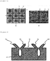
- FIG. 1 is a plan view (A) of the surface of a metal substrate etched according to one embodiment of the present invention and a scanning electron microscope (SEM) image (B) of the metal substrate.
- SEM scanning electron microscope
- burrs 20 extending in a direction away from the etched grooves may be provided continuously or discontinuously along the progress directions X and Y of the etched grooves 10, and a surface area 30 surrounded by the burrs 20 may be provided in a square or rectangular shape.
- the surface of the metal substrate may be in the form of a lattice structure.
- the lattice structure may be a structure formed by the intersection of an etched groove 10 having a progress direction X with an etched groove 10 having a progress direction Y (specifically, intersecting at right angles).
- the light reflectance of the surface of the metal substrate may be adjusted to an appropriate level. Accordingly, the surface of the metal substrate and the first resin layer may be joined more easily, and the bonding strength therebetween may be increased.
- FIG. 2 is a side sectional view of a metal substrate according to an exemplary embodiment of the present invention.
- the surface of the metal substrate may have micrometer (pm)-sized etched grooves 10, and simultaneously, have burrs 20a and 20b provided adjacent to the etched grooves and extending in a direction away from the etched grooves.
- the burrs may be provided on the surface of the metal substrate so as to protrude from the surface of the metal substrate, and the burrs may be provided to protrude away from the etched groove.
- the burr 20b provided adjacent to the one etched groove 10 on the surface of the metal substrate and a burr 20c provided adjacent to the other etched groove 10 on the surface of the metal substrate may continuously or discontinuously extend to face each other, and finally, a fence shape composed of four sides and having the space 30 therein may be provided.
- a burr 20b adjacent to a first etched groove 10 provided on the metal substrate according to an exemplary embodiment of the present invention, and a burr 20c adjacent to a second etched groove 10, may continuously or discontinuously extend to face each other, and a pair of facing burrs (not shown) provided along the progress direction of the other etched groove, and a pair of opposing protrusions (not shown) are connected to the burrs indicated by 20b and 20c, respectively, thus forming a fence shape having the surface area 30 formed therein.
- the sectional shape in the progress direction of the two etched grooves may be very similar. However, when the progress direction of one etched groove and the progress direction of another etched groove intersect at non-right angles, the sectional shape in the progress direction of the two etched grooves may be different.
- the burrs may be provided at an acute angle with respect to a surface of the metal substrate.
- an angle formed between the burrs extending in a direction away from the etched grooves and the surface of the metal substrate may be an acute angle.
- the angle of the burrs with respect to the surface of the metal substrate may be 30° to 80°, 30° to 70°, 35° to 80°, 35° to 70°, 35° to 60°, 40° to 70°, or 40° to 60°.
- the angle of the burrs with respect to a surface of the metal substrate is adjusted within the above range, the light reflectance of the surface of the metal substrate may be effectively lowered, and thus the surface of the metal substrate and the first resin layer may be joined more easily.
- the angle formed between the burrs and the surface of the metal substrate may mean an angle formed between the burrs extending in a direction away from the etched grooves and the surface of the metal substrate.
- the ratio of the depth of the etched groove to the inlet width of the etched groove may be 1:3 to 1:14, or 1:3 to 1:13.
- the etched groove may be sufficiently filled with the first resin layer, and thus the bonding strength between the metal substrate and the first resin layer may increase.
- the inlet width of the etched groove may mean the width of the etched groove on an extension line of the surface of the metal substrate on which the etched groove is formed.
- the depth of the etched groove may mean the maximum distance from the lowest point of the etched groove to the intersection between the extension line of the metal substrate and the central axis of the etched groove.
- the inlet width of the etched groove may be 10 ⁇ m to 25 ⁇ m, or 10 ⁇ m to 20 ⁇ m.
- the depth of the etched groove may be 50 ⁇ m to 250 ⁇ m, 50 ⁇ m to 240 ⁇ m, 60 ⁇ m to 250 ⁇ m, or 60 ⁇ m to 240 ⁇ m.
- the middle width of the etched groove may be 15 ⁇ m to 30 ⁇ m, or 20 ⁇ m to 30 ⁇ m, and the ratio of the middle width of the etched groove to the inlet width of the etched groove may be 1:1.3 to 1:3. In these ranges, the etched groove may be sufficiently filled with the resin layer, and thus the bonding strength between the metal substrate and the first resin layer may increase.
- the middle width of the etched groove may mean a maximum distance between the etched grooves at a point corresponding to half the depth of the etched grooves.
- the light reflectance of the surface of the metal substrate may be controlled within an appropriate range so that the bonding strength between the surface of the metal substrate and the first resin layer may be effectively increased.
- the length from one end to other end of the burr may be 25 ⁇ m to 80 ⁇ m, 25 ⁇ m to 70 ⁇ m, 30 ⁇ m to 80 ⁇ m, 30 ⁇ m to 70 ⁇ m, 30 ⁇ m to 50 ⁇ m, 35 ⁇ m to 70 ⁇ m, or 35 ⁇ m to 50 ⁇ m.
- the height of the burr may be 30 ⁇ m to 100 ⁇ m, 30 ⁇ m to 90 ⁇ m, 40 ⁇ m to 100 ⁇ m, 40 ⁇ m to 90 ⁇ m, 40 ⁇ m to 80 ⁇ m, 50 ⁇ m to 90 ⁇ m, or 50 ⁇ m to 80 ⁇ m.
- the first resin layer may be sufficiently supplied and fixed to the metal substrate with sufficient bonding strength.
- the distance between the central axes of the etched grooves may be 50 ⁇ m to 1,000 ⁇ m, 50 ⁇ m to 800 ⁇ m, 80 ⁇ m to 1,000 ⁇ m, 80 ⁇ m to 800 ⁇ m, 80 ⁇ m to 500 ⁇ m, 100 ⁇ m to 500 ⁇ m, 80 ⁇ m to 250 ⁇ m, or 100 ⁇ m to 250 ⁇ m.
- the distance between the central axes of the etched grooves may mean the distance from the end of one etched groove, at which the depth of the etched groove reaches the maximum value, to the end of the other etched groove.
- the bonding strength between the metal substrate and the first resin layer may become stronger as the height of the burr increases and the distance between the etched grooves decreases.
- a surface of the metal substrate may be modified using a method of subjecting the surface of the metal substrate to sandblast treatment and/or chemical corrosion treatment, in addition to a method of modifying the surface of the metal substrate by irradiating the first laser onto the surface of the metal substrate to form etched grooves and burrs.
- the light reflectance of the surface of the metal substrate at any one wavelength selected from the range of 800 nm to 1,100 nm may be adjusted to a light reflectance of 10% to 30%. Accordingly, the joined body of different materials may be more easily produced.
- a joined body of different materials in which a first resin layer and a metal substrate are joined to each other and the first resin layer and a second resin layer are joined to each other may be produced by sequentially laminating the first resin layer and the second resin layer on a surface of the metal substrate to produce a laminate, and irradiating the surface of the second resin layer with a laser (hereinafter referred to as the second layer).
- FIG. 3 is a schematic illustration of a method for producing a joined body of different materials according to an exemplary embodiment of the present invention.
- FIG. 3 does not include an illustration of the etched grooves and burrs provided on one surface of the metal substrate.
- the laminate may be irradiated with a second laser in a direction from the second resin layer 220 to the metal substrate 100, thereby producing a joined body of different materials.
- the second laser when the laminate is irradiated with the second laser in a direction from the second resin layer to the metal substrate, the second laser may pass through the second resin layer and the first resin layer and reach the surface of the metal substrate.
- the first resin layer and the second resin layer may be fused and joined to each other by the heat energy generated by the laser and absorbed by the second resin layer and the first resin layer, the heat energy reflected from the surface of the metal substrate and re-absorbed by the first resin layer, and the heat energy transferred from the surface of the metal substrate.
- the metal substrate and the first resin layer may be joined to each other while the first resin layer may be melted to fill the inside of the etched grooves formed on the surface of the metal substrate.
- the first resin layer may be supplied to the surface of the metal substrate, the etched grooves and the inner spaces of the fence-shaped burrs, thereby achieving joining between the metal substrate and the first resin layer, that is, between different materials.
- the light transmittance of the first resin layer may be 20% to 70%, and the light transmittance of the first resin layer may be lower that the light transmittance of the second resin layer.
- the second laser may pass through the first resin layer and the second resin layer and effectively reach the surface of the metal substrate, and the metal substrate may be joined to the first resin layer and the first resin layer may be joined to the second resin at the same time by the heat energy generated as the second laser reaches the surface of the metal substrate through the first and second resin layers.
- the light transmittance of the first resin layer at any one wavelength selected from the range of 800 nm to 1,100 nm may be 20% to 70%.
- the light transmittance of the first resin layer at any one wavelength selected from the range of 800 nm to 1,100 nm may be 25% to 65%, 30% to 60%, or 35% to 65%.
- the light transmittance of the first resin may be for a light having a wavelength of 915 nm.
- the second laser may easily reach the surface of the metal substrate, and the first resin layer may effectively absorb heat energy in the process during which the second laser reaches the surface of the metal substrate. Accordingly, the first resin layer may be joined to the second resin layer and the first resin layer may be joined to the metal substrate simultaneously.
- the light absorption rate of the first resin layer at any one wavelength selected from the range of 800 nm to 1,100 nm may be 20% to 50%.
- the light absorption rate of the first resin layer at any one wavelength selected from the range of 800 nm to 1,100 nm may be 25% to 45%, or 30% to 40%. More specifically, the light absorption rate of the first resin layer may be for a light having a wavelength of 915 nm.
- the first resin layer may effectively absorb energy from the second laser, and effectively absorb energy reflected from the one surface of the metal substrate. Accordingly, the first resin layer may be joined to the second resin layer and the first resin layer may be joined to the one surface of the metal substrate.
- the first resin layer may function as both a light transmitting material and a light absorbing material.
- the light reflectance of the surface of the metal substrate at any one wavelength selected from the range of 800 nm to 1,100 nm may be 50% or less.
- the light reflectance of the surface of the metal substrate at any one wavelength selected from the range of 800 nm to 1,100 nm may be 10% to 50%, 15% to 45%, 20% to 35%, 12.5% to 27.5%, 15% to 25%, or 17% to 23%.
- the light reflectance of the surface of the metal substrate may be for a light having a wavelength of 915 nm.
- the second laser that has reached the surface of the metal substrate may be reflected to the first resin layer at a suitable level, thereby transferring heat energy to the first resin layer, and at the same time, the first resin layer at the interface (at which the surface of the metal substrate is in contact with the first resin layer) may be effectively melted by the heat converted from the energy of the second laser absorbed by the surface of the metal substrate. Accordingly, the first resin layer portion located at the interface with the surface of the metal substrate may be effectively melted, and the melted resin may be easily supplied to the surface of the metal substrate, the etched grooves and the inner spaces of the fence-shaped burrs.
- the light transmittance of the second resin layer at any one wavelength selected from the range of 800 nm to 1,100 nm may be 50% to 80%.
- the light transmittance of the second resin layer at any one wavelength selected from the range of 800 nm to 1,100 nm may be 55% to 75%, 65% to 78%, 67.5% to 75%, or 70% to 73%.
- the light transmittance of the second resin layer may be for a light having a wavelength of 915 nm.
- the energy derived from the second laser may be prevented from being concentrated at the second resin layer, thereby effectively preventing the energy from being insufficiently transferred to the first resin layer and the metal substrate.
- the thickness of the first resin layer may be 0.1 mm to 5 mm.
- the thickness of the first resin layer may be 0.5 mm to 4.5 mm, 1.0 mm to 4.0 mm, 1.5 mm to 4.5 mm, 2 mm to 4 mm, or 3 mm to 3.5 mm.
- the thickness of the first resin layer is adjusted within the above-described range, it is possible to increase the efficiency of joining the first resin layer and the second resin layer and the efficiency of joining the first resin layer and the surface of the metal substrate.
- the first resin layer itself may constitute a component of the joined body of different materials.
- any resin layer that is used in the art may be used without limitation as long as it satisfies the above-described light transmittance and light absorption rate.
- the second resin layer any resin layer that is used in the art may be used without limitation as long as it satisfies the above-described light transmittance.
- each of the first resin layer and the second resin layer may include at least one of polypropylene resin, polyamide resin, polycarbonate resin, polybutylene terephthalate, polyethylene terephthalate, and a resin containing a reinforcing material, but the kind thereof is not limited thereto.
- the reinforcing material may include at least one of glass fiber, talc, and carbon fiber, but the kind of the reinforcing material is not limited thereto.
- the laser (the second laser) may be a diode laser having an output of 50 W to 2,000 W.
- the diode laser may mean a laser generated by using a forward semiconductor junction as an active medium.
- the wavelength of the second laser may be a wavelength in the near infrared range.
- the wavelength of the second laser may be any one wavelength selected from the range of 800 nm to 1,100 nm, specifically 915 nm.
- the output of the second laser may be 50 W to 2,000 W, and may be appropriately adjusted depending on the spot size of the laser, the material of the first resin layer and the material of the second resin layer.
- the laser (the second laser) may have a spot size of 100 ⁇ m to 5,000 ⁇ m, and the laminate may be irradiated three times or less with the second laser at an irradiation speed of 10 mm/s to 1,000 mm/s.
- the spot size of the second laser may be 200 ⁇ m to 4,500 ⁇ m, 500 ⁇ m to 3,500 ⁇ m, 750 ⁇ m to 2,000 ⁇ m, or 1,000 ⁇ m to 1,500 ⁇ m, and may be appropriately adjusted depending on the material of the first resin layer and the material of the second resin layer.
- the scanning speed of the second laser may be 50 mm/s to 800 mm/s, 70 mm/s to 500 mm/s, or 100 mm/s to 250 mm/s, and may be appropriately adjusted depending on the material of the first resin layer and the material of the second resin layer.
- the method for producing a joined body of different materials does not cause problems, such as environmental pollution due to chemical hazardous substances, or difficulty in managing mass-production processes, unlike conventional methods for joining different materials.
- an exemplary embodiment of the present invention provides a joined body of different materials including: a metal substrate including two or more etched grooves on a surface thereof and burrs provided adjacent to the etched grooves; and a first resin layer and a second resin layer sequentially laminated on the surface of the metal substrate, wherein the first resin layer has a light transmittance of 20% to 70% at any one wavelength selected from the range of 800 nm to 1,100 nm, and the light transmittance of the first resin layer at the wavelength selected from the range of 800 nm to 1,100 nm is lower than the light transmittance of the second resin layer at the same wavelength.
- the joined body of different materials may have excellent bonding strength between the metal substrate and the first resin layer and excellent bonding strength between the first resin layer and the second resin layer.
- the joined body of different materials according to an exemplary embodiment of the present invention may be produced by the above-described method for producing a joined body of different materials.
- the metal substrate, first resin layer and second resin layer of the joined body of different materials according to an exemplary embodiment of the present invention may be the same as the metal substrate, first resin layer and second resin layer used in the above-described method for producing a joined body of different materials, respectively.
- the first resin layer may fill the inside of the etched grooves and between the metal substrate surface and the burrs, and thus may be joined to the metal substrate. Specifically, as the melted portion of the first resin layer that is in contact with the surface of the metal substrate is supplied to and fills the surface of the metal substrate, the etched grooves and the inner space of the fence-shaped burrs, the first resin layer may be joined to the surface of the metal substrate.
- the first resin layer and the second resin layer may be fused and joined to each other. Specifically, as the interface between the first resin layer and the second resin layer is melted and fused by the heat energy generated in the first resin layer, the first resin layer and the second resin layer may be joined together.
- the thickness of the first resin layer may be 0.1 mm to 5 mm.
- a tackifier, an adhesive or the like is used for joining between a resin layer and a metal substrate.
- the tackifier or adhesive has a thickness of nanometers to micrometers, and merely serves to join the resin layer to the metal substrate, but does not constitute a component of the joined body of different materials.
- the first resin layer of the joined body of different materials according to an exemplary embodiment of the present invention has the above-described thickness, it may serve to join the second resin layer to the metal substrate, and at the same time, may constitute a component of the joined body of different materials.
- the thickness of the metal substrate may be 0.1 mm or more.
- the thickness of the second resin layer may be 0.1 mm to 5 mm.
- the surface of a steel substrate having a thickness of 1.5 mm was etched to form a lattice structure by irradiating the surface in duplicate with two kinds of pulse lasers under the conditions shown in Table 1 below so that the lasers intersect at right angles.
- Table 1 The conditions shown in Table 1 below so that the lasers intersect at right angles.
- etched grooves and burrs generated during the etching were connected to each other along the periphery of the etched grooves, thereby forming fence shapes, each having a space therein.
- the surface of the prepared steel substrate having the etched grooves and the burrs had a light reflectance of about 21% at a wavelength of 915 nm.
- a homopolypropylene resin layer having a thickness of about 1.6 mm was prepared, which had a light transmittance of about 59% and a light absorption rate of about 30% at a wavelength of 915 nm and to which about 30 wt% of glass fiber was added.
- an ethylene-propylene block copolymer resin (CB5230) substrate having a thickness of about 3.2 mm was prepared, which had a light transmittance of about 72% at a wavelength of 915 nm.
- the prepared steel substrate, first resin layer and second resin layer were each cut to a size of 20 mm (width) x 60 mm (length), and then the first resin layer and the second resin layer were fixed onto the surface of the etched steel substrate so as to have an overlap length of 1 cm, thereby preparing a laminate including the steel substrate, the first resin layer and the second resin layer sequentially.
- a diode laser having a wavelength of 915 nm, a spot size of 3 mm and an output of 450 W was repeatedly irradiated twice to the laminate (in the width direction of the laminate) at an irradiation speed of 40 mm/s in the direction from the second resin layer to the steel substrate, thereby producing a joined body of different materials.
- a joined body of different materials was produced in the same manner as Example 1, except that as the first resin layer, a homopolypropylene resin layer having a thickness of about 3.2 mm was prepared, which had a light transmittance of about 35% and a light absorption rate of about 50% at a wavelength of 915 nm and to which about 30 wt% of glass fiber was added.
- a joined body of different materials was produced in the same manner as Example 1, except that a steel substrate (having a light reflectance of about 52% at a wavelength of 915 nm) was prepared, which does not have etched grooves and burrs which are formed by laser irradiation, and as the first resin layer, a homopolypropylene resin layer having a thickness of about 1.6 mm was prepared, which had a light transmittance of about 35% and a light absorption rate of about 50% at a wavelength of 915 nm and to which about 30 wt% of glass fiber was added.
- a joined body of different materials was produced in the same manner as Comparative Example 1, except that a laser-absorbing resin having a light reflectance of about 5% at a wavelength of 915 nm was prepared instead of the steel substrate.
- a joined body of different materials was produced in the same manner as Example 1, except that as the first resin layer, a homopolypropylene resin layer having a thickness of about 1.6 mm was prepared, which had a light transmittance of about 72% and a light absorption rate of about 15% at a wavelength of 915 nm, and as the second resin layer, a homopolypropylene resin layer having a thickness of about 3.2 mm was prepared, which had a light transmittance of about 35% at a wavelength of 915 nm and to which about 30 wt% of glass fiber was added.
- a joined body of different materials was produced in the same manner as Example 1, except that as the first resin layer, a homopolypropylene resin layer having a thickness of about 3.2 mm was prepared, which had a light transmittance of about 80% and a light absorption rate of about 10% at a wavelength of 915 nm, and as the second resin layer, a homopolypropylene substrate having a thickness of about 1.6 mm was prepared, which had a light transmittance of about 72% at a wavelength of 915 nm.
- FIG. 4A is a photograph of the joined body of different materials produced in Example 1 of the present invention
- FIG. 4B is a photograph of the joined body of different materials produced in Example 2 of the present invention.
- (1) in FIG. 4A is a photograph of the lateral side of the joined body of different materials produced in Example 1
- (2) in FIG. 4A is a photograph of the top surface of the joined body of different materials produced in Example 1.
- FIG. 5A is a photograph of the joined body of different materials produced in Comparative Example 1;
- FIG. 5B is a photograph of the joined body of different materials produced in Comparative Example 2;
- FIG. 5C is a photograph of the joined body of different materials produced in Comparative Example 3;
- FIG. 5D is a photograph of the joined body of different materials produced in Comparative Example 4.
- (1) in FIG. 5C is a photograph of the lateral side of the joined body of different materials produced in Comparative Example 3
- (2) in FIG. 5C is a photograph of the top surface of the joined body of different materials produced in Comparative Example 3.
- Comparative Example 1 in which anchoring grooves and burrs were not formed on the surface of the metal substrate, the first resin layer and the second resin layer are joined, but the metal substrate and the first resin layer were not joined.
- Comparative Example 2 in which the laser-absorbing resin having a surface light reflectance of about 5% was used as the substrate, the metal substrate and the first resin layer were joined, but energy transferred from the substrate to the first resin layer by reflection was not sufficient. Hence, the first resin layer and the second resin layer were not joined.
- Example 1 had a bonding strength of 23 MPa
- Example 2 had a bonding strength of 22 MPa. Furthermore, during the measurement of the shear tensile strengths of Examples 1 and 2, the interface between the metal and the plastic was broken, and no separation between the first resin layer and the second resin layer occurred.
Landscapes
- Engineering & Computer Science (AREA)
- Physics & Mathematics (AREA)
- Mechanical Engineering (AREA)
- Optics & Photonics (AREA)
- Health & Medical Sciences (AREA)
- Toxicology (AREA)
- Electromagnetism (AREA)
- Plasma & Fusion (AREA)
- Thermal Sciences (AREA)
- Microelectronics & Electronic Packaging (AREA)
- Laminated Bodies (AREA)
- Lining Or Joining Of Plastics Or The Like (AREA)
- Laser Beam Processing (AREA)
Abstract
Description
- The present specification is a U.S. national stage of international Application No.
PCT/KR2019/012048 filed on September 18, 2019 10-2018-0115903 - The disclosure relates to a method for producing a joined body of different materials and a joined body of different materials.
- In general, joining different materials, such as joining a metal and a resin, is not easy in most cases, because the inherent physical and chemical properties and the surface states of the materials are different. Techniques that may be used for joining such different materials may be classified into bonding with adhesives, mechanical tightening, welding, insert injection, and the like. Among them, the technique that uses an adhesive has the advantage of being used in a simple manner, and thus is a typical and classic method that is most frequently used for joining different materials in electronic products.
- The process that uses an adhesive or mechanical tightening allows for the joining of different materials in a relatively easy manner, but a problem arises in that a junction between the different materials is directly exposed to the outside.
- In addition, in recent years, the development of heterojunction materials composed of resin-resin-metal has been in progress. In the case of such heterojunction materials, joining the resins and joining a resin and a metal are each performed separately, and thus problems arise in that the production process is complicated and the production cost increases.
- Accordingly, there is a need for a technology capable of easily joining a plurality of resin layers and joining a resin and a metal using a relatively simple process.
- Korean Patent No.
KR10-1499665 - The present invention provides a method for producing a joined body of different materials, which is capable of easily joining a plurality of resin layers and joining a resin and a metal, and a joined body of different materials.
- However, problems to be solved by the present invention are not limited to the above-mentioned problem, and other problems which are not mentioned will be clearly understood by those skilled in the art from the following description.
- An exemplary embodiment of the present invention provides a method for producing a joined body of different materials, the method including the steps of: preparing a metal substrate including two or more etched grooves on one surface thereof and burrs provided adjacent to the etched grooves; sequentially laminating a first resin layer and a second resin layer on a surface of the metal substrate, thereby producing a laminate; and irradiating the surface of the second resin layer with a laser, wherein the first resin layer has a light transmittance of 20% to 70% at any one wavelength selected from the range of 800 nm to 1,100 nm, and the light transmittance of the first resin layer at any one wavelength selected from the range of 800 nm to 1,100 nm is lower than the light transmittance of the second resin layer at the same wavelength.
- Another embodiment of the present invention provides a joined body of different materials including: a metal substrate including two or more etched grooves on one surface thereof and burrs provided adjacent to the etched grooves; and a first resin layer and a second resin layer sequentially laminated on the surface of the metal substrate, wherein the first resin layer has a light transmittance of 20% to 70% at any one wavelength selected from the range of 800 nm to 1,100 nm, and the light transmittance of the first resin layer at any one wavelength selected from the range of 800 nm to 1,100 nm is lower than the light transmittance of the second resin layer at the same wavelength.
- The method for producing a joined body of different materials according to an exemplary embodiment of the present invention has an advantage in that joining the resin layers and joining a resin layer and a metal substrate may be achieved simultaneously by a simple method.
- The joined body of different materials according to an exemplary embodiment of the present invention may have excellent bonding strength between the metal substrate and the first resin layer and excellent bonding strength between the first resin layer and the second resin layer.
- The effects of the present invention are not limited to the above-described effect, and effects which are not mentioned will be clearly understood by those skilled in the art from the present specification and the accompanying drawings.
-
-
FIG. 1 is a plan view (A) of the surface of a metal substrate etched according to an exemplary embodiment of the present invention and a scanning electron microscope (SEM) image (B) of the metal substrate. -
FIG. 2 is a sectional view of a metal substrate according to an exemplary embodiment of the present invention. -
FIG. 3 is a schematic illustration of a method for producing a joined body of different materials according to an exemplary embodiment of the present invention. -
FIG. 4A is a photograph of a joined body of different materials produced in Example 1 of the present invention. -
FIG. 4B is a photograph of a joined body of different materials produced in Example 2 of the present invention. -
FIG. 5A is a photograph of a joined body of different materials produced in Comparative Example 1;FIG. 5B is a photograph of a joined body of different materials produced in Comparative Example 2;FIG. 5C is a photograph of a lateral surface of a joined body of different materials produced in Comparative Example 3;FIG. 5D is a photograph of a top surface of a joined body of different materials produced in Comparative Example 4. - Throughout the present specification, it is to be understood that when any part is referred to as "including" any component, it does not exclude other components, but may further include other components, unless otherwise specified.
- Throughout the present specification, when any member is referred to as being "on" another member, it refers to not only a case where any member is in contact with another member, but also a case where a third member exists between the two members.
- Throughout the present specification, it is to be understood that when any component is referred to as being "included" in any part, it is not formed by a special or limited method, but is placed or provided on any part.
- As used in the present specification, the term "step of doing ..." or "step of ..." does not mean"a step for ...".
- In the present specification, the thickness of any member may be measured in comparison with the corresponding scale in a scanning electron microscope (SEM; Scanning Electron Microscope S-4800, HITACHI) image of the side of the member, or may be measured using a thickness gauge.
- In the present specification, the "light transmittance" of a member may mean the percentage of the amount of light transmitted through the member relative to the amount of light incident on the member. Furthermore, the "light reflectance" of a member may mean the percentage of the amount of light reflected from the member relative to the amount of light incident on the member. In addition, the "light absorption rate" of a member may mean the ratio of the amount of light absorbed by the member relative to the amount of light incident on the member, the light transmittance of a member may mean a value obtained by subtracting the light absorption rate (%) and light reflectance (%) of the member from 100%. In addition, the light transmittance, light reflectance and light absorption rate of a member may be values at a specific wavelength, measured using a spectrophotometer (SolidSpec-3700, Shimadzu).
- Hereinafter, the present specification will be described in more detail.
- An exemplary embodiment of the present invention provides a method for producing a joined body of different materials, the method including the steps of: preparing a metal substrate including two or more etched grooves on one surface thereof and burrs provided adjacent to the etched grooves; sequentially laminating a first resin layer and a second resin layer on the surface of the metal substrate, thereby producing a laminate; and irradiating the surface of the second resin layer with a laser, wherein the first resin layer has a light transmittance of 20% to 70% at any one wavelength selected from the range of 800 nm to 1,100 nm, and the light transmittance of the first resin layer at any one wavelength selected from the range of 800 nm to 1,100 nm is lower than the light transmittance of the second resin layer at the same wavelength.
- The method for producing a joined body of different materials according to an exemplary embodiment of the present invention has an advantage in that joining between resin layers and joining between a resin layer and a metal substrate may be achieved at the same time by a simple method.
- According to an exemplary embodiment of the present invention, it may be preferable to use, as the metal substrate, a material that may be easily patterned by laser irradiation and has an appropriate light absorption rate, although a conventional material may be used as the metal substrate without particular limitation. For example, pure metals such as aluminum (Al) and titanium (Ti), alloys such as stainless steel (STS), and the like may be used as the metal substrate.
- According to an exemplary embodiment of the present invention, the shape of the metal substrate may be applied without particular limitation, as long as it may be etched by laser irradiation and may be smoothly joined with the resin. For example, the metal substrate may have shapes, such as cylindrical and polyhedron shapes, and may include a flat surface and a curved surface.
- According to an exemplary embodiment of the present invention, a laser (hereinafter referred to as the first laser) may be irradiated onto a surface of the metal substrate, thereby preparing a metal substrate including two more etched grooves and burrs provided adjacent to the etched grooves.
- According to an exemplary embodiment of the present invention, the first laser may be a pulse laser having a wavelength of 1,064 nm. In addition, the output of the first laser may be 20 W to 200 W, specifically 20 W to 100 W, 20 W to 50 W, or 20 W to 40 W.
- According to an exemplary embodiment of the present invention, the repetition frequency of the first laser may be 30 kHz to 600 kHz, specifically 30 kHz to 200 kHz, 40 kHz to 600 kHz, or 40 kHz to 200 kHz.
- In the present specification, the repetition frequency of the first laser may mean the number of cycles per second of the pulse laser.
- According to an exemplary embodiment of the present invention, the scanning speed of the first laser may be 100 mm/s to 1,000 mm/s, specifically 100 mm/s to 400 mm/s, 200 mm/s to 1,000 mm/s, 200 mm/s to 400 mm/s, 200 mm/s to 450 mm/s, 300 mm/s to 400 mm/s, or 300 mm/s to 450 mm/s.
- In the present specification, the scanning speed of the pulse laser may mean a speed at which the laser irradiated moves from one point to another point.
- According to an exemplary embodiment of the present invention, the number of irradiations of the first laser may be 1 to 10, specifically 1 to 8, 1 to 4, 2 to 10, 2 to 8, 2 to 4, or 4 to 8. In addition, the pulse width of the first laser may be 15 ns to 220 ns.
- According to an exemplary embodiment of the present invention, the spot size of the first laser may be 15 µm to 50 µm, specifically 25 µm to 50 µm, 30 µm to 50 µm, or 35 µm to 50 µm.
- In the present specification, the spot size (or beam size) may mean the maximum distance from one end to the other end of the focal point of the pulse laser.
- According to an exemplary embodiment of the present invention, the peak output of the first laser may be 1.5 kW to 6 kW, specifically 1.5 kW to 3.4 kW, 1.9 kW to 6 kW, or 1.9 kW to 3.4 kW. In addition, the pulse energy of the first laser may be 0.1 mJ to 2 mJ, specifically 0.1 mJ to 1 mJ, 0.5 mJ to 2 mJ, or 0.5 mJ to 1 mJ.
- When conditions for irradiating a surface of the metal substrate with the first laser are adjusted as described above, the depth of the etched groove, the inlet width of the etched groove, the middle width of the etched groove, the length of the burr, the height of the burr, and the range of the angle formed between the burr and the surface of the metal substrate may be controlled as described below. Accordingly, it is possible to increase the bonding strength between the metal substrate and the first resin layer.
- According to an exemplary embodiment of the present invention, under the energy conditions of the first laser, the material evaporated from the wall of the etched groove and the inlet of the etched groove may be re-condensed, and the burr protruding from the metal substrate may be relatively roughly formed. Accordingly, it is possible to easily form an area, in which the metal substrate and the first resin layer may be joined, and an anchoring structure.
- According to an exemplary embodiment of the present invention, the surface of the metal substrate may be irradiated with the first laser in the depth direction of the etched groove, and as a result, a portion of the metal substrate may be melted in a direction away from the central axis of the etched groove on the surface of the metal substrate and may have the burrs. In addition, the remaining portion of the metal substrate other than the portion having the burrs may be melted toward the central axis of the etched groove in the metal substrate having the etched groove formed therein by irradiating with the first laser. Accordingly, it is possible to form an etched groove having a relatively narrow inlet width.
- Specifically, as a result of irradiating the surface with the first laser, melting of the metal substrate may proceed rapidly. Then, as the focus of the first laser moves, the melted metal substrate may be cooled, and an etched groove having a relatively narrow inlet width compared to the middle width may be formed as the melted metal substrate is cooled at a portion adjacent to the etched groove.
- According to an exemplary embodiment of the present invention, in the process of irradiating a surface of the metal substrate with the first laser, etched grooves may be formed on the surface of the metal substrate along the traveling direction of the first laser. That is, the traveling direction of the first laser may coincide with the progress direction of the etched groove.
- In addition, a surface of the metal substrate may be irradiated with two or more first lasers, and the traveling directions of the two or more first lasers may intersect. Specifically, the traveling direction of one of the first lasers and the traveling direction of another first laser may intersect. When a surface of the metal substrate is etched by irradiation the two or more first lasers a lattice structure may be formed with burrs protruding from the surface of the etched metal substrate may be formed adjacent to the etched grooves on the surface of the metal substrate so as to protrude away from the etched grooves.
- According to an exemplary embodiment of the present invention, an micrometer-sized etched groove may be formed on a surface of the metal substrate by irradiating the metal substrate with the first laser, and at the same time, burrs may be formed adjacent to the etched groove extending in a direction away from the groove. In addition, since the etched groove may be formed along the traveling direction of the first laser, burrs adjacent to each of the etched grooves formed along the traveling direction of one of the first lasers and the etched groove formed along the traveling direction of another first laser may continuously extend to face each other, and finally, a fence shape composed of four sides and having a space therein may be formed. Specifically, one of the burrs adjacent to one of the etched grooves and one of the burrs adjacent to another etched groove may continuously extend to face each other, and a pair of facing burrs formed along the traveling direction of another first laser may be connected to the other burrs, respectively, thereby forming a fence shape having a space therein.
- According to an exemplary embodiment of the present invention, the progress direction of a first etched groove and the progress direction of a second etched groove may be parallel to each other. In addition, the progress direction of the first etched groove and the progress direction of the second etched groove may intersect at right angles or at non-right angles.
-
FIG. 1 is a plan view (A) of the surface of a metal substrate etched according to one embodiment of the present invention and a scanning electron microscope (SEM) image (B) of the metal substrate. - Referring to
FIG. 1 , it can be seen that when the progress direction X of one etchedgroove 10 and the progress direction Y of another etchedgroove 10 intersect at right angles, burrs 20 extending in a direction away from the etched grooves may be provided continuously or discontinuously along the progress directions X and Y of the etchedgrooves 10, and asurface area 30 surrounded by the burrs 20 may be provided in a square or rectangular shape. - In addition, referring to
FIG. 1 , the surface of the metal substrate may be in the form of a lattice structure. Specifically, as shown inFIG. 1 , the lattice structure may be a structure formed by the intersection of an etchedgroove 10 having a progress direction X with an etchedgroove 10 having a progress direction Y (specifically, intersecting at right angles). - As described above, as the pattern is formed in a lattice structure on a surface of the metal substrate by the one etched groove and the other etched groove, the light reflectance of the surface of the metal substrate may be adjusted to an appropriate level. Accordingly, the surface of the metal substrate and the first resin layer may be joined more easily, and the bonding strength therebetween may be increased.
-
FIG. 2 is a side sectional view of a metal substrate according to an exemplary embodiment of the present invention. - As illustrated in
FIG. 2 , the surface of the metal substrate may have micrometer (pm)-sizedetched grooves 10, and simultaneously, haveburrs FIG. 2 , the burrs may be provided on the surface of the metal substrate so as to protrude from the surface of the metal substrate, and the burrs may be provided to protrude away from the etched groove. - In addition, as shown in
FIGS. 1 and 2 , theburr 20b provided adjacent to the one etchedgroove 10 on the surface of the metal substrate and aburr 20c provided adjacent to the other etchedgroove 10 on the surface of the metal substrate may continuously or discontinuously extend to face each other, and finally, a fence shape composed of four sides and having thespace 30 therein may be provided. - Furthermore, as illustrated in
FIG. 2 , aburr 20b adjacent to a first etchedgroove 10 provided on the metal substrate according to an exemplary embodiment of the present invention, and aburr 20c adjacent to a second etchedgroove 10, may continuously or discontinuously extend to face each other, and a pair of facing burrs (not shown) provided along the progress direction of the other etched groove, and a pair of opposing protrusions (not shown) are connected to the burrs indicated by 20b and 20c, respectively, thus forming a fence shape having thesurface area 30 formed therein. - In addition, when the progress direction of one etched groove and the progress direction of another etched groove intersect at right angles, the sectional shape in the progress direction of the two etched grooves may be very similar. However, when the progress direction of one etched groove and the progress direction of another etched groove intersect at non-right angles, the sectional shape in the progress direction of the two etched grooves may be different.
- According to an exemplary embodiment of the present invention, the burrs may be provided at an acute angle with respect to a surface of the metal substrate. Specifically, an angle formed between the burrs extending in a direction away from the etched grooves and the surface of the metal substrate may be an acute angle.
- According to an exemplary embodiment of the present invention, the angle of the burrs with respect to the surface of the metal substrate may be 30° to 80°, 30° to 70°, 35° to 80°, 35° to 70°, 35° to 60°, 40° to 70°, or 40° to 60°. When the angle of the burrs with respect to a surface of the metal substrate is adjusted within the above range, the light reflectance of the surface of the metal substrate may be effectively lowered, and thus the surface of the metal substrate and the first resin layer may be joined more easily.
- In the present specification, the angle formed between the burrs and the surface of the metal substrate may mean an angle formed between the burrs extending in a direction away from the etched grooves and the surface of the metal substrate.
- According to an exemplary embodiment of the present invention, the ratio of the depth of the etched groove to the inlet width of the etched groove may be 1:3 to 1:14, or 1:3 to 1:13. In this range, the etched groove may be sufficiently filled with the first resin layer, and thus the bonding strength between the metal substrate and the first resin layer may increase.
- In the present specification, the inlet width of the etched groove may mean the width of the etched groove on an extension line of the surface of the metal substrate on which the etched groove is formed.
- In the present specification, the depth of the etched groove may mean the maximum distance from the lowest point of the etched groove to the intersection between the extension line of the metal substrate and the central axis of the etched groove.
- According to an exemplary embodiment of the present invention, the inlet width of the etched groove may be 10 µm to 25 µm, or 10 µm to 20 µm. In addition, the depth of the etched groove may be 50 µm to 250 µm, 50 µm to 240 µm, 60 µm to 250 µm, or 60 µm to 240 µm.
- Furthermore, according to an exemplary embodiment of the present invention, the middle width of the etched groove may be 15 µm to 30 µm, or 20 µm to 30 µm, and the ratio of the middle width of the etched groove to the inlet width of the etched groove may be 1:1.3 to 1:3. In these ranges, the etched groove may be sufficiently filled with the resin layer, and thus the bonding strength between the metal substrate and the first resin layer may increase.
- In the present specification, the middle width of the etched groove may mean a maximum distance between the etched grooves at a point corresponding to half the depth of the etched grooves.
- According to an exemplary embodiment of the present invention, when the inlet width, middle width and depth of the etched groove are adjusted within the above-described ranges, the light reflectance of the surface of the metal substrate may be controlled within an appropriate range so that the bonding strength between the surface of the metal substrate and the first resin layer may be effectively increased.
- According to an exemplary embodiment of the present invention, the length from one end to other end of the burr may be 25 µm to 80 µm, 25 µm to 70 µm, 30 µm to 80 µm, 30 µm to 70 µm, 30 µm to 50 µm, 35 µm to 70 µm, or 35 µm to 50 µm.
- In addition, according to an exemplary embodiment of the present invention, the height of the burr may be 30 µm to 100 µm, 30 µm to 90 µm, 40 µm to 100 µm, 40 µm to 90 µm, 40 µm to 80 µm, 50 µm to 90 µm, or 50 µm to 80 µm.
- In the above-described ranges of the length of the burr and the height of the burr, the first resin layer may be sufficiently supplied and fixed to the metal substrate with sufficient bonding strength.
- According to an exemplary embodiment of the present invention, the distance between the central axes of the etched grooves may be 50 µm to 1,000 µm, 50 µm to 800 µm, 80 µm to 1,000 µm, 80 µm to 800 µm, 80 µm to 500 µm, 100 µm to 500 µm, 80 µm to 250 µm, or 100 µm to 250 µm.
- In this distance range, it is possible to prevent the facing burrs from being merged with each other, thereby preventing the formation of an empty space where the resin layer may not be supplied. In addition, it is possible to relatively increase the area of joining between the structure formed by the etched grooves and the burrs and the resin layer, thereby providing a sufficient bonding strength therebetween.
- In the present specification, the distance between the central axes of the etched grooves may mean the distance from the end of one etched groove, at which the depth of the etched groove reaches the maximum value, to the end of the other etched groove.
- According to an exemplary embodiment of the present invention, the bonding strength between the metal substrate and the first resin layer may become stronger as the height of the burr increases and the distance between the etched grooves decreases.
- According to an exemplary embodiment of the present invention, a surface of the metal substrate may be modified using a method of subjecting the surface of the metal substrate to sandblast treatment and/or chemical corrosion treatment, in addition to a method of modifying the surface of the metal substrate by irradiating the first laser onto the surface of the metal substrate to form etched grooves and burrs. As the surface of the metal substrate is modified, the light reflectance of the surface of the metal substrate at any one wavelength selected from the range of 800 nm to 1,100 nm may be adjusted to a light reflectance of 10% to 30%. Accordingly, the joined body of different materials may be more easily produced.
- According to an exemplary embodiment of the present invention, a joined body of different materials in which a first resin layer and a metal substrate are joined to each other and the first resin layer and a second resin layer are joined to each other may be produced by sequentially laminating the first resin layer and the second resin layer on a surface of the metal substrate to produce a laminate, and irradiating the surface of the second resin layer with a laser (hereinafter referred to as the second layer).
-
FIG. 3 is a schematic illustration of a method for producing a joined body of different materials according to an exemplary embodiment of the present invention.FIG. 3 does not include an illustration of the etched grooves and burrs provided on one surface of the metal substrate. - As illustrated in
FIG. 3 , for a laminate in which afirst resin layer 210 is provided on a surface of ametal substrate 100 and asecond resin layer 220 is provided on a surface of thefirst resin layer 210, the laminate may be irradiated with a second laser in a direction from thesecond resin layer 220 to themetal substrate 100, thereby producing a joined body of different materials. - According to an exemplary embodiment of the present invention, when the laminate is irradiated with the second laser in a direction from the second resin layer to the metal substrate, the second laser may pass through the second resin layer and the first resin layer and reach the surface of the metal substrate.
- In the process during which the second laser reaches the surface of the metal substrate from the second resin layer, the first resin layer and the second resin layer may be fused and joined to each other by the heat energy generated by the laser and absorbed by the second resin layer and the first resin layer, the heat energy reflected from the surface of the metal substrate and re-absorbed by the first resin layer, and the heat energy transferred from the surface of the metal substrate. In addition, the metal substrate and the first resin layer may be joined to each other while the first resin layer may be melted to fill the inside of the etched grooves formed on the surface of the metal substrate. Specifically, as the first resin layer is melted, it may be supplied to the surface of the metal substrate, the etched grooves and the inner spaces of the fence-shaped burrs, thereby achieving joining between the metal substrate and the first resin layer, that is, between different materials.
- According to an exemplary embodiment of the present invention, at any one wavelength selected from the range of 800 nm to 1,100 nm, the light transmittance of the first resin layer may be 20% to 70%, and the light transmittance of the first resin layer may be lower that the light transmittance of the second resin layer. In this case, the second laser may pass through the first resin layer and the second resin layer and effectively reach the surface of the metal substrate, and the metal substrate may be joined to the first resin layer and the first resin layer may be joined to the second resin at the same time by the heat energy generated as the second laser reaches the surface of the metal substrate through the first and second resin layers.
- According to an exemplary embodiment of the present invention, the light transmittance of the first resin layer at any one wavelength selected from the range of 800 nm to 1,100 nm may be 20% to 70%. Specifically, the light transmittance of the first resin layer at any one wavelength selected from the range of 800 nm to 1,100 nm may be 25% to 65%, 30% to 60%, or 35% to 65%. More specifically, the light transmittance of the first resin may be for a light having a wavelength of 915 nm.
- When the light transmittance of the first resin layer is adjusted within the above-described range, the second laser may easily reach the surface of the metal substrate, and the first resin layer may effectively absorb heat energy in the process during which the second laser reaches the surface of the metal substrate. Accordingly, the first resin layer may be joined to the second resin layer and the first resin layer may be joined to the metal substrate simultaneously.
- According to an exemplary embodiment of the present invention, the light absorption rate of the first resin layer at any one wavelength selected from the range of 800 nm to 1,100 nm may be 20% to 50%. Specifically, the light absorption rate of the first resin layer at any one wavelength selected from the range of 800 nm to 1,100 nm may be 25% to 45%, or 30% to 40%. More specifically, the light absorption rate of the first resin layer may be for a light having a wavelength of 915 nm.
- When the light absorption rate of the first resin layer is adjusted within the above-described range, in the process during which the second laser reaches the one surface of the metal substrate, the first resin layer may effectively absorb energy from the second laser, and effectively absorb energy reflected from the one surface of the metal substrate. Accordingly, the first resin layer may be joined to the second resin layer and the first resin layer may be joined to the one surface of the metal substrate.
- That is, the first resin layer may function as both a light transmitting material and a light absorbing material.
- According to an exemplary embodiment of the present invention, the light reflectance of the surface of the metal substrate at any one wavelength selected from the range of 800 nm to 1,100 nm may be 50% or less. Specifically, the light reflectance of the surface of the metal substrate at any one wavelength selected from the range of 800 nm to 1,100 nm may be 10% to 50%, 15% to 45%, 20% to 35%, 12.5% to 27.5%, 15% to 25%, or 17% to 23%. More specifically, the light reflectance of the surface of the metal substrate may be for a light having a wavelength of 915 nm.
- When the light reflectance of the surface of the metal substrate is within the above-described range, the second laser that has reached the surface of the metal substrate may be reflected to the first resin layer at a suitable level, thereby transferring heat energy to the first resin layer, and at the same time, the first resin layer at the interface (at which the surface of the metal substrate is in contact with the first resin layer) may be effectively melted by the heat converted from the energy of the second laser absorbed by the surface of the metal substrate. Accordingly, the first resin layer portion located at the interface with the surface of the metal substrate may be effectively melted, and the melted resin may be easily supplied to the surface of the metal substrate, the etched grooves and the inner spaces of the fence-shaped burrs.
- According to an exemplary embodiment of the present invention, the light transmittance of the second resin layer at any one wavelength selected from the range of 800 nm to 1,100 nm may be 50% to 80%. Specifically, the light transmittance of the second resin layer at any one wavelength selected from the range of 800 nm to 1,100 nm may be 55% to 75%, 65% to 78%, 67.5% to 75%, or 70% to 73%. More specifically, the light transmittance of the second resin layer may be for a light having a wavelength of 915 nm.
- When the light transmittance of the second resin layer is within the above-described range, the energy derived from the second laser may be prevented from being concentrated at the second resin layer, thereby effectively preventing the energy from being insufficiently transferred to the first resin layer and the metal substrate.
- According to an exemplary embodiment of the present invention, the thickness of the first resin layer may be 0.1 mm to 5 mm. Specifically, the thickness of the first resin layer may be 0.5 mm to 4.5 mm, 1.0 mm to 4.0 mm, 1.5 mm to 4.5 mm, 2 mm to 4 mm, or 3 mm to 3.5 mm. When the thickness of the first resin layer is adjusted within the above-described range, it is possible to increase the efficiency of joining the first resin layer and the second resin layer and the efficiency of joining the first resin layer and the surface of the metal substrate. In addition, when the thickness of the first resin layer is within the above-described range, the first resin layer itself may constitute a component of the joined body of different materials.
- According to an exemplary embodiment of the present invention, as the first resin layer, any resin layer that is used in the art may be used without limitation as long as it satisfies the above-described light transmittance and light absorption rate. In addition, as the second resin layer, any resin layer that is used in the art may be used without limitation as long as it satisfies the above-described light transmittance. For example, each of the first resin layer and the second resin layer may include at least one of polypropylene resin, polyamide resin, polycarbonate resin, polybutylene terephthalate, polyethylene terephthalate, and a resin containing a reinforcing material, but the kind thereof is not limited thereto.
- In addition, the reinforcing material may include at least one of glass fiber, talc, and carbon fiber, but the kind of the reinforcing material is not limited thereto.
- According to an exemplary embodiment of the present invention, the laser (the second laser) may be a diode laser having an output of 50 W to 2,000 W. The diode laser may mean a laser generated by using a forward semiconductor junction as an active medium.
- According to an exemplary embodiment of the present invention, the wavelength of the second laser may be a wavelength in the near infrared range. Specifically, the wavelength of the second laser may be any one wavelength selected from the range of 800 nm to 1,100 nm, specifically 915 nm.
- According to an exemplary embodiment of the present invention, the output of the second laser may be 50 W to 2,000 W, and may be appropriately adjusted depending on the spot size of the laser, the material of the first resin layer and the material of the second resin layer.
- According to an exemplary embodiment of the present invention, the laser (the second laser) may have a spot size of 100 µm to 5,000 µm, and the laminate may be irradiated three times or less with the second laser at an irradiation speed of 10 mm/s to 1,000 mm/s.
- According to an exemplary embodiment of the present invention, the spot size of the second laser may be 200 µm to 4,500 µm, 500 µm to 3,500 µm, 750 µm to 2,000 µm, or 1,000 µm to 1,500 µm, and may be appropriately adjusted depending on the material of the first resin layer and the material of the second resin layer. In addition, the scanning speed of the second laser may be 50 mm/s to 800 mm/s, 70 mm/s to 500 mm/s, or 100 mm/s to 250 mm/s, and may be appropriately adjusted depending on the material of the first resin layer and the material of the second resin layer.
- According to an exemplary embodiment of the present invention, the number of times the laminate is irradiated with the second laser may be 3 or less, specifically 2 or less. That is, the method for producing a joined body of different materials according to an exemplary embodiment of the present invention may easily join the metal substrate and the first resin layer and join the first resin layer and the second resin layer even though the number of irradiations of the second laser is small.
- In addition, the method for producing a joined body of different materials according to an exemplary embodiment of the present invention does not cause problems, such as environmental pollution due to chemical hazardous substances, or difficulty in managing mass-production processes, unlike conventional methods for joining different materials. In addition, it is possible to minimize the number of process steps, thereby improving the efficiency of production of the joined body of different materials and effectively reducing production cost.
- In addition, an exemplary embodiment of the present invention provides a joined body of different materials including: a metal substrate including two or more etched grooves on a surface thereof and burrs provided adjacent to the etched grooves; and a first resin layer and a second resin layer sequentially laminated on the surface of the metal substrate, wherein the first resin layer has a light transmittance of 20% to 70% at any one wavelength selected from the range of 800 nm to 1,100 nm, and the light transmittance of the first resin layer at the wavelength selected from the range of 800 nm to 1,100 nm is lower than the light transmittance of the second resin layer at the same wavelength.
- The joined body of different materials according to an exemplary embodiment of the present invention may have excellent bonding strength between the metal substrate and the first resin layer and excellent bonding strength between the first resin layer and the second resin layer.
- The joined body of different materials according to an exemplary embodiment of the present invention may be produced by the above-described method for producing a joined body of different materials. In addition, the metal substrate, first resin layer and second resin layer of the joined body of different materials according to an exemplary embodiment of the present invention may be the same as the metal substrate, first resin layer and second resin layer used in the above-described method for producing a joined body of different materials, respectively.
- According to an exemplary embodiment of the present invention, the first resin layer may fill the inside of the etched grooves and between the metal substrate surface and the burrs, and thus may be joined to the metal substrate. Specifically, as the melted portion of the first resin layer that is in contact with the surface of the metal substrate is supplied to and fills the surface of the metal substrate, the etched grooves and the inner space of the fence-shaped burrs, the first resin layer may be joined to the surface of the metal substrate.
- According to an exemplary embodiment of the present invention, the first resin layer and the second resin layer may be fused and joined to each other. Specifically, as the interface between the first resin layer and the second resin layer is melted and fused by the heat energy generated in the first resin layer, the first resin layer and the second resin layer may be joined together.
- According to an exemplary embodiment of the present invention, the thickness of the first resin layer may be 0.1 mm to 5 mm. For a conventional joined body of different materials, a tackifier, an adhesive or the like is used for joining between a resin layer and a metal substrate. In this case, the tackifier or adhesive has a thickness of nanometers to micrometers, and merely serves to join the resin layer to the metal substrate, but does not constitute a component of the joined body of different materials. On the contrary, as the first resin layer of the joined body of different materials according to an exemplary embodiment of the present invention has the above-described thickness, it may serve to join the second resin layer to the metal substrate, and at the same time, may constitute a component of the joined body of different materials.
- According to an exemplary embodiment of the present invention, the thickness of the metal substrate may be 0.1 mm or more. In addition, the thickness of the second resin layer may be 0.1 mm to 5 mm.
- Hereinafter, the present invention will be described in detail with reference to examples. However, the examples according to the present invention may be modified into various different forms, and the scope of the present invention is not interpreted as being limited to the examples described below. The examples of the present specification are provided to more completely explain the present invention to those skilled in the art.
- The surface of a steel substrate having a thickness of 1.5 mm was etched to form a lattice structure by irradiating the surface in duplicate with two kinds of pulse lasers under the conditions shown in Table 1 below so that the lasers intersect at right angles. Through laser irradiation, etched grooves and burrs generated during the etching were connected to each other along the periphery of the etched grooves, thereby forming fence shapes, each having a space therein.
[Table 1] Pulse width (ns) Spot size (µm) Output (W) Repletion frequency (kHz) Scanning speed (mm/s) Peak output (kW) Energy density (kJ/cm2) Number of irradiations Example 1 220 35 30 40 200 3.2 73 1 - The average depth, inlet width and middle width of the etched grooves formed as described above were measured, and the results of the measurement are shown in Table 2 below. Specifically, in order to measure the average depth, inlet width and middle width of the etched grooves and the average depth and height of the burrs, the etched aluminum substrate was cut in the vertical direction of the interface portion and polished, thereby preparing specimens. In addition, the average value of the measured values of the respective features (depths of the etched grooves, the inlet widths of the etched grooves, the middle widths of the etched grooves, the lengths of the burrs, and the heights of the burrs) in 10 to 20 grooves for each specimen were calculated, and the results of the calculation are shown in Table 2 below.
[Table 2] Depth (µm) of etched groove Inlet width (µm) of etched groove Middle width (µm) of etched groove Length (µm) of burr Height (µm) of burr Example 1 80 12 25 45 35 - At this time, the surface of the prepared steel substrate having the etched grooves and the burrs had a light reflectance of about 21% at a wavelength of 915 nm.
- As a first resin layer, a homopolypropylene resin layer having a thickness of about 1.6 mm was prepared, which had a light transmittance of about 59% and a light absorption rate of about 30% at a wavelength of 915 nm and to which about 30 wt% of glass fiber was added. In addition, as a second resin layer, an ethylene-propylene block copolymer resin (CB5230) substrate having a thickness of about 3.2 mm was prepared, which had a light transmittance of about 72% at a wavelength of 915 nm.
- Next, the prepared steel substrate, first resin layer and second resin layer were each cut to a size of 20 mm (width) x 60 mm (length), and then the first resin layer and the second resin layer were fixed onto the surface of the etched steel substrate so as to have an overlap length of 1 cm, thereby preparing a laminate including the steel substrate, the first resin layer and the second resin layer sequentially. Next, a diode laser having a wavelength of 915 nm, a spot size of 3 mm and an output of 450 W was repeatedly irradiated twice to the laminate (in the width direction of the laminate) at an irradiation speed of 40 mm/s in the direction from the second resin layer to the steel substrate, thereby producing a joined body of different materials.
- A joined body of different materials was produced in the same manner as Example 1, except that as the first resin layer, a homopolypropylene resin layer having a thickness of about 3.2 mm was prepared, which had a light transmittance of about 35% and a light absorption rate of about 50% at a wavelength of 915 nm and to which about 30 wt% of glass fiber was added.
- A joined body of different materials was produced in the same manner as Example 1, except that a steel substrate (having a light reflectance of about 52% at a wavelength of 915 nm) was prepared, which does not have etched grooves and burrs which are formed by laser irradiation, and as the first resin layer, a homopolypropylene resin layer having a thickness of about 1.6 mm was prepared, which had a light transmittance of about 35% and a light absorption rate of about 50% at a wavelength of 915 nm and to which about 30 wt% of glass fiber was added.
- A joined body of different materials was produced in the same manner as Comparative Example 1, except that a laser-absorbing resin having a light reflectance of about 5% at a wavelength of 915 nm was prepared instead of the steel substrate.
- A joined body of different materials was produced in the same manner as Example 1, except that as the first resin layer, a homopolypropylene resin layer having a thickness of about 1.6 mm was prepared, which had a light transmittance of about 72% and a light absorption rate of about 15% at a wavelength of 915 nm, and as the second resin layer, a homopolypropylene resin layer having a thickness of about 3.2 mm was prepared, which had a light transmittance of about 35% at a wavelength of 915 nm and to which about 30 wt% of glass fiber was added.
- A joined body of different materials was produced in the same manner as Example 1, except that as the first resin layer, a homopolypropylene resin layer having a thickness of about 3.2 mm was prepared, which had a light transmittance of about 80% and a light absorption rate of about 10% at a wavelength of 915 nm, and as the second resin layer, a homopolypropylene substrate having a thickness of about 1.6 mm was prepared, which had a light transmittance of about 72% at a wavelength of 915 nm.
-
FIG. 4A is a photograph of the joined body of different materials produced in Example 1 of the present invention, andFIG. 4B is a photograph of the joined body of different materials produced in Example 2 of the present invention. Specifically, (1) inFIG. 4A is a photograph of the lateral side of the joined body of different materials produced in Example 1, and (2) inFIG. 4A is a photograph of the top surface of the joined body of different materials produced in Example 1. - Referring to
FIGS. 4A and4B , it was confirmed that the methods for producing a joined body of different materials according to Examples 1 and 2 of the present invention could effectively join the metal substrate and the first resin layer and join the first resin layer and the second resin layer at the same time. In addition, as shown inFIG. 4B , the surface of the second resin layer irradiated with the laser was not damaged. -
FIG. 5A is a photograph of the joined body of different materials produced in Comparative Example 1;FIG. 5B is a photograph of the joined body of different materials produced in Comparative Example 2;FIG. 5C is a photograph of the joined body of different materials produced in Comparative Example 3; andFIG. 5D is a photograph of the joined body of different materials produced in Comparative Example 4. Specifically, (1) inFIG. 5C is a photograph of the lateral side of the joined body of different materials produced in Comparative Example 3, and (2) inFIG. 5C is a photograph of the top surface of the joined body of different materials produced in Comparative Example 3. - As shown in
FIG. 5A , in Comparative Example 1, in which anchoring grooves and burrs were not formed on the surface of the metal substrate, the first resin layer and the second resin layer are joined, but the metal substrate and the first resin layer were not joined. In addition, as shown inFIG. 5B , in Comparative Example 2, in which the laser-absorbing resin having a surface light reflectance of about 5% was used as the substrate, the metal substrate and the first resin layer were joined, but energy transferred from the substrate to the first resin layer by reflection was not sufficient. Hence, the first resin layer and the second resin layer were not joined. - In addition, referring to (1) of
FIG. 5C , it was confirmed that in the case of Comparative Example 3 in which the light transmittance and light absorption rate of the first resin layer and the light transmittance of the second resin layer were out of the ranges specified in the present invention and the light transmittance of the second resin layer was lower than the light transmittance of the first resin layer, most of the energy of the laser irradiated was concentrated at the second resin layer and the energy was not sufficiently transferred to the first resin layer and the metal substrate through the second resin layer. Hence, neither the metal substrate and the first resin layer nor the first resin layer and the second resin layer were joined. In addition, as shown inFIG. 5D , most of the energy generated during irradiation of the laminate with the laser was concentrated at the second resin layer. Hence, the surface of the second resin layer was damaged. - Furthermore, referring to
FIG. 5D , it was confirmed that in the case of Comparative Example 4 in which the light transmittance of the first resin layer was higher than 70% and the light transmittance of the second resin layer was 72%, the laser sufficiently reached the metal substrate, and thus joining between the metal substrate and the first resin layer was achieved, but the first resin layer did not sufficiently absorb energy due to its high light transmittance, and hence joining between the first resin layer and the second resin layer was not achieved. - Both ends of each of the joined bodies of different materials produced in Examples 1 and 2 and Comparative Examples 1 to 4 were fixed to a Zwick universal testing machine (model: Z020), and the bonding strength of each joined body was measured by measuring the shear tensile strength using the machine at a speed of 50 mm/min.
- The bonding strength was measured by measuring the shear tensile strength according to Test Example 1 above, and as a result, it was confirmed that Example 1 had a bonding strength of 23 MPa, and Example 2 had a bonding strength of 22 MPa. Furthermore, during the measurement of the shear tensile strengths of Examples 1 and 2, the interface between the metal and the plastic was broken, and no separation between the first resin layer and the second resin layer occurred.
- In comparison with this, in the case of Comparative Examples 1 and 3, joining between the steel substrate and the first resin layer was not achieved during the production of the joined body of different materials. In the case of Comparative Example 2, joining between the laser-absorbing resin and the first resin layer occurred, but joining between the first resin layer and the second resin layer did not occur. In addition, in the case of Comparative Example 4, only joining between the steel substrate and the first resin layer occurred, but joining between the first resin layer and the second resin layer did not occur. Hence, it was impossible to measure the bonding strengths of the joined bodies of different materials, which are Comparative Examples 1 to 4.
-
- 10:
- etched grooves
- 20, 20a, 20b, 20c and 20d:
- burrs
- 30:
- surface area
- 100:
- metal substrate
- 210:
- first resin layer
- 220:
- second resin layer
- 300:
- laser-absorbing resin
Claims (10)
- A method for producing a joined body comprising different materials joined together, the method comprising the steps of:preparing a metal substrate comprising two or more etched grooves on a surface thereof and burrs provided adjacent to each of the two or more etched grooves;sequentially laminating a first resin layer and a second resin layer on the surface of the metal substrate, thereby producing a laminate; andirradiating a surface of the second resin layer with a laser,wherein the first resin layer has a light transmittance of 20% to 70% at any one wavelength selected from a range of 800 nm to 1,100 nm, andthe light transmittance of the first resin layer at the any one wavelength is lower than a light transmittance of the second resin layer at the any one wavelength.
- The method of claim 1, wherein the light transmittance of the first resin layer at the any one wavelength is 20% to 50%.
- The method of claim 1, wherein the one surface of the metal substrate has a light reflectance of 50% or less at the any one wavelength.
- The method of claim 1, wherein the second resin layer has a light transmittance of 50% to 80% at the any one wavelength.
- The method of claim 1, wherein the first resin layer has a thickness of 0.1 mm to 5 mm.
- The method of claim 1, wherein the laser is a diode laser having an output of 50 W to 2,000 W.
- The method of claim 1, wherein the surface of the second resin layer is irradiated with the laser three times or less at an irradiation speed of 10 mm/s to 1,000 mm/s, and wherein the laser has a spot size of 100 µm to 5,000 µm.
- A joined body comprising different materials joined together, the joined body comprising:a metal substrate comprising two or more etched grooves on a surface thereof and burrs provided adjacent to each of the two or more etched grooves; anda first resin layer and a second resin layer sequentially laminated on the surface of the metal substrate,wherein the first resin layer has a light transmittance of 20% to 70% at any one wavelength selected from a range of 800 nm to 1,100 nm, andwherein the light transmittance of the first resin layer at the any one wavelength is lower than a light transmittance of the second resin layer at the same wavelength.
- The joined body of claim 8, wherein the first resin layer fills an inside of each of the two or more etched grooves and between the surface of the metal substrate and the burrs, and wherein the first resin layer is joined to the metal substrate.
- The joined body of claim 8, wherein the first resin layer has a thickness of 0.1 mm to 5 mm.
Applications Claiming Priority (2)
| Application Number | Priority Date | Filing Date | Title |
|---|---|---|---|
| KR1020180115903A KR102631904B1 (en) | 2018-09-28 | 2018-09-28 | Method for manufacturing different material joint body and different material joint body |
| PCT/KR2019/012048 WO2020067672A1 (en) | 2018-09-28 | 2019-09-18 | Method for manufacturing bonded body of different materials and bonded structure of different materials |
Publications (2)
| Publication Number | Publication Date |
|---|---|
| EP3797985A1 true EP3797985A1 (en) | 2021-03-31 |
| EP3797985A4 EP3797985A4 (en) | 2021-10-20 |
Family
ID=69953014
Family Applications (1)
| Application Number | Title | Priority Date | Filing Date |
|---|---|---|---|
| EP19865390.9A Pending EP3797985A4 (en) | 2018-09-28 | 2019-09-18 | PROCESS FOR MANUFACTURING A BOUND BODY OF DIFFERENT MATERIALS AND BOUND STRUCTURE OF DIFFERENT MATERIALS |
Country Status (6)
| Country | Link |
|---|---|
| US (1) | US11904553B2 (en) |
| EP (1) | EP3797985A4 (en) |
| JP (1) | JP7053109B2 (en) |
| KR (1) | KR102631904B1 (en) |
| CN (1) | CN112351879B (en) |
| WO (1) | WO2020067672A1 (en) |
Families Citing this family (4)
| Publication number | Priority date | Publication date | Assignee | Title |
|---|---|---|---|---|
| CN117943695A (en) * | 2019-12-26 | 2024-04-30 | 株式会社尼康 | Processing device and processing method |
| JP2023008908A (en) * | 2021-06-30 | 2023-01-19 | 東レ・デュポン株式会社 | Manufacturing method of laser welded body |
| CN113787255A (en) * | 2021-09-30 | 2021-12-14 | 苏州大学 | A kind of laser welding method of transparent plastic film |
| CN121403053A (en) * | 2025-11-27 | 2026-01-27 | 中南大学 | A method and equipment for welding highly stable heterogeneous materials |
Family Cites Families (18)
| Publication number | Priority date | Publication date | Assignee | Title |
|---|---|---|---|---|
| JP4300806B2 (en) | 2003-01-22 | 2009-07-22 | 住友ベークライト株式会社 | Metal foil with resin and multilayer printed circuit board |
| JP2005041073A (en) * | 2003-07-28 | 2005-02-17 | Toyoda Mach Works Ltd | Laser welding method for welding resin materials |
| DE10338588A1 (en) | 2003-08-22 | 2005-03-24 | Bayer Ag | Method for joining molded parts made of plastic and metal |
| JP4042664B2 (en) | 2003-09-17 | 2008-02-06 | 株式会社ジェイテクト | Laser welding method of resin material |
| JP2007182003A (en) | 2006-01-10 | 2007-07-19 | Stanley Electric Co Ltd | Laser welding method of resin material |
| JP5835945B2 (en) * | 2010-08-11 | 2015-12-24 | 株式会社日立製作所 | Laser bonding method |
| JP2012223889A (en) | 2011-04-15 | 2012-11-15 | Hitachi Ltd | Method for laser bonding |
| JP2012232531A (en) | 2011-05-06 | 2012-11-29 | Daicel Corp | Laser welding method of resin molded body and metal molded body and composite molded body |
| KR101499665B1 (en) | 2012-05-29 | 2015-03-06 | 포리프라스틱 가부시키가이샤 | Method for manufacturing composite molded article |
| JP6332897B2 (en) | 2012-07-25 | 2018-05-30 | 旭化成株式会社 | Composite material and manufacturing method thereof |
| JP2014046599A (en) * | 2012-08-31 | 2014-03-17 | Nippon Light Metal Co Ltd | Metal member for producing metal-resin complex, and production method of the member |
| JP5889775B2 (en) * | 2012-09-04 | 2016-03-22 | ダイセルポリマー株式会社 | Composite molded body and manufacturing method thereof |
| JP2015116684A (en) | 2013-12-17 | 2015-06-25 | ヤマセ電気株式会社 | Method for joining metal surface to dissimilar material, production method for dissimilar material-joined metal material, and dissimilar material-joined metal material |
| JP5816763B1 (en) | 2015-01-19 | 2015-11-18 | ヤマセ電気株式会社 | Heterogeneous material bonded metal material with airtightness at the interface between different materials and metal material, Heterogeneous material bonded material with airtightness at the interface between different materials |
| JP2016141092A (en) | 2015-02-04 | 2016-08-08 | オムロン株式会社 | Production method of joint structure, and joint structure |
| JP2016159578A (en) | 2015-03-04 | 2016-09-05 | オムロン株式会社 | Bonding method, manufacturing method of bonded structure, and bonded structure |
| DE102016215493A1 (en) * | 2016-08-18 | 2018-02-22 | Fraunhofer-Gesellschaft zur Förderung der angewandten Forschung e.V. | Hybrid composite material between a metal surface and a polymeric material surface and method for producing the hybrid composite material |
| CN109789516B (en) * | 2016-09-30 | 2021-06-15 | 株式会社Lg化学 | Bonded body of different materials and method for producing same |
-
2018
- 2018-09-28 KR KR1020180115903A patent/KR102631904B1/en active Active
-
2019
- 2019-09-18 EP EP19865390.9A patent/EP3797985A4/en active Pending
- 2019-09-18 JP JP2020570864A patent/JP7053109B2/en active Active
- 2019-09-18 WO PCT/KR2019/012048 patent/WO2020067672A1/en not_active Ceased
- 2019-09-18 US US17/256,501 patent/US11904553B2/en active Active
- 2019-09-18 CN CN201980042636.3A patent/CN112351879B/en active Active
Also Published As
| Publication number | Publication date |
|---|---|
| CN112351879B (en) | 2022-11-08 |
| KR102631904B1 (en) | 2024-01-31 |
| KR20200036363A (en) | 2020-04-07 |
| US11904553B2 (en) | 2024-02-20 |
| US20210276306A1 (en) | 2021-09-09 |
| EP3797985A4 (en) | 2021-10-20 |
| JP2021528282A (en) | 2021-10-21 |
| JP7053109B2 (en) | 2022-04-12 |
| CN112351879A (en) | 2021-02-09 |
| WO2020067672A1 (en) | 2020-04-02 |
Similar Documents
| Publication | Publication Date | Title |
|---|---|---|
| KR102111948B1 (en) | Different material joint body and method for manufacturing the same | |
| EP3797985A1 (en) | Method for manufacturing bonded body of different materials and bonded structure of different materials | |
| EP2979836B1 (en) | Composite molded body production method | |
| CN100467253C (en) | Resin molded body and its preparation method | |
| DE102016112708B4 (en) | Molded body for a sheet metal laser welding clamp | |
| JP2013122973A (en) | Connection structure of metal foil, connection method of the same, and capacitor | |
| JPS60228131A (en) | Mechanical jointing of heterogeneous synthetic resin materials | |
| JP7683799B2 (en) | Manufacturing method of composite member, and composite member | |
| KR102932128B1 (en) | Different material joint body and method for manufacturing the same | |
| KR20230031092A (en) | Method and apparatus for joining different materials | |
| EP3695932B1 (en) | Method for producing a bonded body of different materials | |
| KR20200046880A (en) | Method for manufacturing different material joint body and different material joint body | |
| JPH06106371A (en) | Laser beam welding method | |
| JPS6274631A (en) | Joining of synthetic resin material | |
| JP7748125B2 (en) | Flat-hole connection method by pulsed laser shock, its device and application | |
| JP3426396B2 (en) | Honeycomb panel and welding apparatus therefor | |
| JP2021117119A (en) | Method for forming laminate body | |
| KR20190053332A (en) | Different material joint body and method of manufacturing the same | |
| JPS60222229A (en) | Method for bonding different kinds of synthetic resin materials | |
| JP2024034680A (en) | Laser welding method | |
| KR20200041170A (en) | Methallic glass-resin laminate, and method for manufacturing the same | |
| JPS6250314B2 (en) |
Legal Events
| Date | Code | Title | Description |
|---|---|---|---|
| STAA | Information on the status of an ep patent application or granted ep patent |
Free format text: STATUS: THE INTERNATIONAL PUBLICATION HAS BEEN MADE |
|
| PUAI | Public reference made under article 153(3) epc to a published international application that has entered the european phase |
Free format text: ORIGINAL CODE: 0009012 |
|
| STAA | Information on the status of an ep patent application or granted ep patent |
Free format text: STATUS: REQUEST FOR EXAMINATION WAS MADE |
|
| 17P | Request for examination filed |
Effective date: 20201221 |
|
| AK | Designated contracting states |
Kind code of ref document: A1 Designated state(s): AL AT BE BG CH CY CZ DE DK EE ES FI FR GB GR HR HU IE IS IT LI LT LU LV MC MK MT NL NO PL PT RO RS SE SI SK SM TR |
|
| A4 | Supplementary search report drawn up and despatched |
Effective date: 20210920 |
|
| RIC1 | Information provided on ipc code assigned before grant |
Ipc: B32B 27/36 20060101ALI20210914BHEP Ipc: B32B 27/34 20060101ALI20210914BHEP Ipc: B32B 27/32 20060101ALI20210914BHEP Ipc: B32B 27/20 20060101ALI20210914BHEP Ipc: B32B 15/20 20060101ALI20210914BHEP Ipc: B32B 15/18 20060101ALI20210914BHEP Ipc: B32B 15/09 20060101ALI20210914BHEP Ipc: B32B 15/088 20060101ALI20210914BHEP Ipc: B32B 15/085 20060101ALI20210914BHEP Ipc: B32B 7/023 20190101ALI20210914BHEP Ipc: B29C 65/44 20060101ALI20210914BHEP Ipc: B23K 26/364 20140101ALI20210914BHEP Ipc: B32B 27/08 20060101ALI20210914BHEP Ipc: B32B 15/08 20060101ALI20210914BHEP Ipc: B32B 3/30 20060101AFI20210914BHEP |
|
| STAA | Information on the status of an ep patent application or granted ep patent |
Free format text: STATUS: EXAMINATION IS IN PROGRESS |
|
| 17Q | First examination report despatched |
Effective date: 20240115 |